1
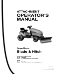
ATTACHMENT
N
ep o
ro t fo
du r
ct
io
n
OPERATOR’S
MANUAL
42” Snow Blade
R
Mfg. No.
1694919
Description
42” Remote Angling Snow Blade
1732529-B
Revision: B
2
N
ep o
ro t fo
du r
ct
io
n
R
Table of Contents
4
4
5
6
Assembly.. ......................................................................................
Initial Setup................................................................................
Install Reach on to Tractor .........................................................
Attach Lift Assembly to Snow Blade ..........................................
Attach Snow Blade to Tractor.....................................................
Install Snow Blade Arm .............................................................
Attche Control Arm Support Bracket to Tractor ..........................
Operation .......................................................................................
Checks before Starting ..............................................................
Engine and Ground Speed Selection ........................................
Transporting ..............................................................................
Starting and Stopping ................................................................
Changing Angle of Blade...........................................................
Snow Plowing Tips ....................................................................
Operation .......................................................................................
Checks before Starting ..............................................................
Snow Blade removal..................................................................
7
7
8
9
9
10
11
12
12
12
12
12
12
12
12
12
12
Maintenance ..................................................................................
Schedule for NormaL Care ........................................................
General Lubrication...............................................................
Snow Blade Removal ....................................................................
Travel Height Adjustment ...........................................................
Snow Blade Removal ................................................................
Trouble Shooting ...........................................................................
13
13
13
14
14
14
16
Storage ...........................................................................................
17
Warranty .........................................................................................
18
R
N
ep o
ro t fo
du r
ct
io
n
Operator Safety .............................................................................
General Warnings ......................................................................
Safety Decals ............................................................................
Features and Controls ..................................................................
NOTE: In these instructions, “left” and “right” are referenced from the
operating position.
3
Operator Safety
Read these safety rules and follow them closely. Failure to obey these rules could result in loss of control of
unit, severe personal injury or death to you, or bystanders, or damage to property or equipment. The triangle
in text signifies important cautions or warnings which must be followed.
GENERAL WARNING
WARNING
• Know the unit’s controls and how to stop quickly. READ
THE OPERATOR’S MANUALS.
• Read and obey all safety decals.
• Only allow responsible adults, who are familiar with the
instructions, to operate the unit.
• Disengage the PTO. Shut off the engine and wait for
all moving parts to stop before attaching, adjusting, or
disconnecting any part of the collection system.
• Use only attachments or accessories designed for
your machine. See your dealer for a complete list of
recommended attachments or accessories.
• Keep the area of operation clear of all persons,
particularly small children, and pets.
Before leaving the operator’s position for any reason,
engage the parking brake, disengage the PTO, stop the
engine and remove the key.
To reduce fire hazard, keep the engine, rider and mower
free of grass, leaves and excess grease. Do not stop
or park rider over dry leaves, grass or combustible
materials.
CAUTION
Before you begin operating the unit be certain you have
read all of the safety and operational information of this
instruction sheet, as well as the Operator’s Manual for
the tractor and any other attachments.
N
ep o
ro t fo
du r
ct
io
n
• Never direct discharge towards bystanders.
ALWAYS shut off the tractor. Disengage the PTO, and
allow all moving parts to stop BEFORE disconnecting or
clearing tube, or emptying catcher.
• Make sure all hardware is secure and that dozer blade
is in good operating condition.
• Check to be sure all safety devices and shields are in
place.
• Check that all adjustments are correct before using this
unit.
• Gasoline is highly flammable. Follow all precautions
listed in your tractor’s operator’s manual.
• Always wear eye protection while operating and
performing adjustments to protect eyes from debris
thrown by the dozer.
• Turn off the PTO to disengage the blades when not
mowing.
R
• DO NOT mow in reverse unless absolutely necessary.
Always look down and behind before and while
travelling in reverse.
• DO NOT turn sharply when travelling alongside a
building or any object. Slow down before turning.
• DO NOT carry passengers.
• For added stability and to prevent tipping or loss of
control:
a. Use reduced speed on uneven ground and when
turning corners.
b. Reduce loads on hillsides. It is recommended that the
collection system be kept only half full when negotiating
any slopes. Start mowing on slopes when the collection
system is empty.
c. Mow up and down the face of slopes; never across
the face of any slope.
• Never operate on slopes greater than 17.6% (10°).
4
Operator Safety
Safety Decals
PREPARATION
• Disengage the PTO before making any adjustments.
• Never attempt to make any adjustments while engine
is running.
• Thoroughly inspect the area where the dozer is to be
operated and remove all foreign objects.
• Adjust the skid shoe height to clear gravel or crushed
stone surface. See the Adjustments section for
procedure.
Several safety labels are installed on the unit to remind you
of important information while you are operating your unit.
All DANGER, WARNING, CAUTION and instructional
messages on your rider, attachments and mower should
be carefully read and obeyed. Personal bodily injury can
result when these instructions are not followed. The safety
decals below are on your product.
If any decals are lost or damaged, replace them at once.
See your local dealer for replacements.
These labels are easily applied and will act as a constant
visual reminder to you, and others who may use the
equipment, to follow the safety instructions necessary for
safe, effective operation.
PREPARATION
• Always clear snow up and down the face of slopes,
never across the face. Exercise extreme caution
when changing direction on slopes. Do not attempt to
clear steep slopes.
WARNING Thrown Objects Hazard
WARNING
Thrown objects hazard
• Objects thrown by the mower can seriously
injure or kill you.
N
ep o
ro t fo
du r
ct
io
n
• Exercise extreme caution when operating on, or
crossing, gravel drives, walks or roads. Stay alert for
hidden hazards or traffic.
Attachment Decal
• After striking an object or if unit starts to vibrate
abnormally, stop the engine and remove the key.
Check for the cause and any damage before
restarting. Before any inspection, make sure all
moving parts have stopped.
• Do not open the hopper while the mower blades
are turning.
• Do not operate the mower without the complete
catcher in place.
1732819
• Take all possible precautions before leaving
operator’s position. Lower the attachment, set the
parking brake, stop the engine and remove the key.
• Never operate near glass enclosures, automobiles,
window wells, dropoffs, etc.
• Do not put hands or feet near or under the dozer
blade. Keep clear of the dozer blade at all times.
• Do not overload machine capacity by attempting to
clear too much material at too fast a rate.
R
• Never operate unit at high transport speeds on
slippery surfaces. Use care when travelling in
reverse.
• Never operate the dozer blade without good visibility
or light. Always be sure your feet are properly placed
on the footrests and keep a firm hold on the steering
wheel.
• Do not run the engine indoors.
• Never allow anyone in front of the unit.
5
Features & Controls
WARNING
A
Before you begin operating the tractor with the dozer
blade attachment, make certain you have:
• Read and understood the instructions in the tractor
Operator’s Manual.
• Become thoroughly familiar with all of the tractor
controls and their operation, including how to safely
and properly start and stop the unit.
• Practice driving in an open area—without dozing—to
become accustomed to the unit.
Control Functions
The information below briefly describes the function of
individual controls. Operating the tractor and dozer require
the combined use of these controls and additional controls
whose operation is described in the tractor Operator’s
Manual.
Blade Angle Control Lever
N
ep o
ro t fo
du r
ct
io
n
Please Take a moment and familiarize yourself with
the name, location, and function of these controls so
that you will better understand the safety and operating
instructions provided in this manual.
The blade angle release lever (A, Figure 1) controls a
spring-loaded plate which locks the blade in one of three
positions.
Turn the lever counterclockwise to release the angling
mechanism and move the blade left or right. Push the
angling lever forward fully to lock the blade in the left position. Pull the lever fully back to lock the blade in the right
position. Move the lever slowly past center to lock in the
centered position.
Attachment Lift
R
NOTE: It is easier to change the angle of the blade with
the attachment raised.
The attachment lift lever (B, Figure 1) raises and lowers
the dozer blade. To RAISE attachment pull back on lever.
To LOWER an attachment, move the lever forward.
6
Figure 1
B
Assembly
21
17
20
4
26
5
29
18
20
22
2
2
3
1
*
6
7
27
19
2
28
24
16
2
8
9
N
ep o
ro t fo
du r
ct
io
n
15
10
13
11
23
25 13
14
Figure 2
Initial Setup
Ref
1
2
3
4
5
6
7
8
9
10
11
12
13
14
15
Qty
1
7
1
1
1
1
1
1
1
2
1
2
2
1
1
R
12
Description
Extension Spring
Hair Pin
Flat Washer
Lift Rod Assembly
Lift Pivot
Lock Washer
.875” Cap Screw
Reach
Bell Crank
Latch Rod
Hitch Lift Assembly
1.25” Cap Screw
Nut
Snow Blade Assembly
Spring
Ref
16
17
18
19
20
21
22
23
24
25
26
27
28
29
*
Qty
Description
1
1
1
3
3
1
1
2
2
2
1
1
1
1
1
Long Eye Bolt
Short Eye Bolt
Bottom Blade Rod
1.00” Cap Screw
Flange Nut
Top Blade Rod
Control Arm Support Bracket
Washer
Hex Nut
Spacer
Large Hair Pin
Reach Support Rod
Cotter Pin
Lock Nut
“C” Lift Rod (Part tractor lift assembly)
7
Assembly
Install Reach on to Tractor
1. Remove mower deck.
2. On right side of reach (A, Figure 3), install the bell crank
(B) through the front holes .
6. Slide the reach (A, Figure 5) under tractor and lift to
slide reach mounting arms (B) over reach support shaft
(C).
3. Place reach on floor in front of tractor, with the hitch
mounting arms towards the rear of the tractor.
B
A
A
C
B
Figure 3
N
ep o
ro t fo
du r
ct
io
n
Figure 5
4. On underside of tractor frame, insert reach support rod
(A, Figure 4) as shown and secure with the
cotter pin (B) on inside of frame.
IMPORTANT: The cotter pin must be located along the
inside edge of the tractor frame.
5. Slightly bend longer end of cotter pin. See Figure 4
inset.
7. At front of the machine, locate latch rod (A, Figure 6)
and remove hair pin (B) and slide out of reach (C).
8. Turn the front wheels fully to the left.
9. Lift the reach (C) and place the latch rod (D) onto the
tractor frame support fingers (E).
10. From the left side of the tractor, re-install latch rod (A)
through the holes on each side of reach.
11. Secure the latch rod (A) with the hair clip (B).
NOTE: Keep the handle portion of the hitch latch pin
towards the front of the tractor.
R
E
A
A
B
B
D
C
B
Figure 4
Figure 6
8
Assembly
Attaching Hitch Lift Assembly to Snow Blade
1. Attach the hitch lift assembly (A, Figure 7) to snow
blade assembly (B) using 1.25” cap screw (C), washer
(D), spacer (E) and nut (F).
4. Insert the large loop of spring (A, Figure 9) through the
hole (B) in hitch lift assembly and then the small loop
through eyebolt (C).
5. Tighten the hex nuts (D) to adjust and apply tension to
the spring.
A
D
F
E
A
D
E
F
C
B
N
ep o
ro t fo
du r
ct
io
n
B
C
Figure 9
Attaching Snow Blade to Tractor
Figure 7
2. Secure the hex nut (A, Figure 8) onto long eyebolt (B).
Tighten the eyebolt locknut toward top of threads. See
Figure 8 inset.
3. Insert long eyebolt / locknut through the hole (C) at top
of the blade and secure with additional hex nut (D).
1. Position snow blade assembly in front of tractor.
NOTE: Make sure that the bell crank (A, Figure 10) is
rotated to a 45° angle before installing the snow blade
assembly as shown in inset.
2. Align mounting holes on snow blade frame with the
mounting holes in the reach.
3. Insert latch rod (B) and secure with hair pin (C).
A
R
B
A
45°
C
B
C
D
Figure 8
Figure 10
9
Assembly
Install Snow Blade Lift Arm
Note: The following steps are preformed under right rear
fender.
1. Move the mower deck lift arm to the “LOWERED”
position.
4. Install the extension spring (A, Figure 13) into square
hole (B) at the rear edge of the tractor frame.
5. Secure the other end of extension spring to the “C” lift
rod (C) on the mower deck lift arm.
2. Insert .875” cap screw (A, Figure 11), lock washer (B)
into top hole of mower lift arm (C).
C
B
A
A
B
C
N
ep o
ro t fo
du r
ct
io
n
Figure 13
6. Attach the lower ball joint (A, Figure 14) of lift rod
assembly to the bell crank (S) and secure with the hair
pin (C).
Figure 11
3. Slide the lift pivot (D, Figure 12), lift rod assembly (E),
and washer (F) onto cap screw (B) and secure large
hair pin (G).
Note: Make sure to position the washer between the
hair pin and the lift arm.
G
Figure 12
10
E
D
B
R
F
A
Figure 14
B
C
Assembly
Attaching Control Arm Support Bracket to
Tractor
1. On right side of tractor, install the control arm support
bracket (A, Figure 15) using a 1.00” cap screw (B) and
flange nut (C) to the tractor frame.
2. On the outside of the control arm support bracket (A)
install the short eye bolt (D), and secure with nut (E).
E
D
5. Slide the control arm assembly (A, Figure 18) through
the two adjustment arm joints (B). Secure the control
arm with four hair pins (C).
A
C
B
B
A
Figure 18
6. Tighten ball joint locking nuts (A, Figure 19).
C
N
ep o
ro t fo
du r
ct
io
n
Figure 15
3. Insert the top blade rod (A, Figure 16) through the eye
bolt hole (B).
A
A
A
Figure 19
B
R
7. Lower the blade to the ground and adjust the skid
shoes. See Skid Shoe Adjustment, page 17.
Figure 16
4. Attach the lower portion of the control arm (A, Figure 17)
to the upper control arm (B) using the 1.00” cap screws
(C) and lock nuts (D).
C
A
B
D
Figure 17
11
Operations
Transporting
DANGER
OPERATING ON SLOPES CAN BE DANGEROUS
Never operate on slopes greater than 17.6% (10°)
which is a rise of 3-1/2 feet (106cm) vertically in 10 feet
(607cm) horizontally.
Operate the unit at a slow ground speed when driving
onto slope. Avoid using brakes to control ground speed.
When operating on slopes that are greater than 15 %
(8.5°) but less than 17.6%, use additional wheel weights
or counterweights.
In addition to counterweights, use extra caution when
operating on slopes. Drive UP and DOWN the slope,
never across the face, use caution when changing
directions and DO NOT START OR STOP ON SLOPE.
For additional traction, tire chains and a weight box can
be added. Maximum weight added to tractor should
not exceed 35 lbs. per wheel and 100 additional lbs. in
weight box.
WARNING
Perform the Safety System Interlock test found in your
tractor Operator’s Manual. If tractor does not pass the
test, do not operate the tractor. See your authorized
dealer. Under no circumstances should you attempt to
defeat the safety system.
Use caution when plowing a snow covered area. Snow
can cover objects such as curbs, drop-offs, and other
obstacles. Be familiar with the area you are plowing.
To prevent an explosion or fire, never store the tractor
with fuel in the tank inside a building where an ignition
source is present.
Checks Before Starting
R
1. Refer to the Maintenance & Adjustments sections of
this manual and perform any needed service. Also,
refer to the tractor Operator’s Manual and perform any
required service.
2. Remove any objects from the work area which might
interfere with plowing activity.
3. Adjust the skid shoes to desired height. See Skid Shoe
Adjustment.
4. Make sure all hardware is present and secure.
Engine & Ground Speed Selection
Always run the engine at full throttle.
Set tractor speed to obtain the needed power to move
the material. Operate at a safe speed, depending on
conditions, so that you have complete control of the
tractor. Rear wheel weights and chains are recommended
for slippery surfaces.
A rear weight carrier is recommended for additional
traction.
12
Starting & Stopping
1. Start the tractor engine. Set engine throttle to full.
2. Raise the attachment lift and travel to the work site.
3. Set the angling control to the desired angle.
4. Lower the attachment lift and begin plowing.
5. Raise the plow before backing up.
6. To stop the tractor, set ground speed to neutral and set
the parking brake. Before leaving the seat, stop the
engine, set the parking brake, remove the key, and wait
for all moving parts to stop.
Changing Angle of the Blade:
See Figure 1 for location of Controls.
NOTE: It is easier to change the angle of the blade with the
attachment raised.
N
ep o
ro t fo
du r
ct
io
n
IMPORTANT
Note: To prevent damage to the unit, always raise the dozer
blade BEFORE turning or backing up.
For maximum ground clearance, transport the blade
to and from work areas fully raised and angled straight
ahead.
1. Raise the attachment lift.
2. Turn the lever counterclockwise to release the angling
mechanism and move the blade left or right. Push the
angling lever forward fully to lock the blade in the left
position. Pull the lever fully back to lock the blade in the
right position. Move the lever slowly over center to lock
in the centered position.
Snow Plowing Tips
• Determine the best snow removal pattern before
beginning.
• Plan the pattern so that you avoid pushing snow onto
cleared areas.
• When land contour permits, it is best to travel in the
longest direction to minimize turning.
• In very deep or heavy snow, it may be necessary to
make the first pass with dozer blade partially raised,
then repeat each pass with the blade lowered to
clear the material left on the surface. Also, it may be
necessary to clear less than the full width of the dozer
blade or reduce ground speed.
• Snow tends to freeze into solid banks when plowed off
a driveway or other large area. Because of this you
may want to plow snow several feet past the edge of
the drive to allow space for future plowing to build up.
• If pushing snow past the edges of driveways or
sidewalks, be careful not to tear up the grass buried
under snow next to the drive or sidewalk. Lift the blade
several inches off the ground to avoid damaging the
grass.
• Spinning tires with tire chains can leave unsightly marks
or permanent damage to asphalt or concrete driveways
or sidewalks. Avoid sudden stops or starts.
Figure 20
Schedule For Normal Care
WARNING
N
ep o
ro t fo
du r
ct
io
n
Maintenance
General Lubrication
Schedule
Clean snow and ice from
the snow blade.
After each use.
Lubricate snow blade.
Every 10 hours or at
least once a year.
R
To avoid serious injury, perform maintenance on the
unit only when the engine is stopped and all moving
parts have stopped. Always remove the ignition key
before beginning maintenance or adjustments to prevent
accidental starting of the engine.
Care Required
Lubricate the snow blade as shown in Figure 21. Where
an oil can is shown use 30 weight oil. Where a grease
gun is shown, use lithium grease. Lubricate the following
areas:
• Grease the blade pivot.
• Oil the blade lock pawl
• Apply grease to the plastic wear surface above the bell
crank and to the bell crank.
13
Snow Blade Removal
Travel Height Adjustment
4. Remove the hair pin (A, Figure 23) from bell crank (B)
and remove the lift arm assembly (C).
CAUTION
Make sure to shut off the engine and lock the tractor
brakes or block the rear wheels before beginning the
snow blade removal process.
B
1. Fully raise the snow blade off the ground. If the
transport height is not correct, lower the snow blade to
the ground and remove the lift arm (A, Figure 21) from
the bell crank (B).
2. Loosen the lift arm ball joint lock nut (C) and rotate the
ball joint (A) either right or left to adjust the proper lift
height.
3. Reinstall and secure the lift arm and test adjustment.
Repeat as needed.
A
C
Figure 23
N
ep o
ro t fo
du r
ct
io
n
5. Remove lift arm assembly (A, Figure 24) from the
mower lift arm (B) by removing the hair pin (C) and flat
washer (D).
NOTE: Leave the lift pivot attached to the mower deck
lift arm.
B
D
C
A
Figure 21
Snow Blade Removal
C
1. Lower the snow blade to the ground.
2. Remove the four (4) hair pins (A, Figure 22) from the
control arm (B) from ball joints (C) and remove the
control arm from the snow blade assembly.
R
A
3. Remove the control arm from the tractor.
NOTE: The control arm support bracket can be left on
the tractor.
B
A
C
Figure 22
14
Figure 24
B
Snow Blade Removal
6. Turn the front wheels fully to the left.
7. Remove the hair pin (A, Figure 25) and slide the latch
rod (B) out from the reach (C).
CAUTION
9. At back of tractor, slide reach mounting arms (A, Figure
26) out of the reach support shaft (B). Slide the reach
from under the tractor.
NOTE: The reach support shaft (B) may be left in
position and will not interfere with the operation of the
lawn mower deck.
Make sure to support the front of the hitch assembly as
is will be loose when the latch rod has been removed.
8. Lift the reach (C) off the support fingers (D) and place
front end of the reach onto the floor.
D
B
B
N
ep o
ro t fo
du r
ct
io
n
C
A
C
Figure 25
IMPORTANT
Note: Inspect the snow blade assembly, hitch assembly,
and all component parts for signs of wear or damage. Have
these items repaired or serviced before reinstalling the
snow blade onto the tractor.
R
B
Figure 26
15
TroubleShooting
Troubleshooting
WARNING
• To avoid serious injury, perform maintenance on the
tractor or snow blade only when the engine is stopped
and the parking brake engaged.
• Always remove the ignition key, disconnect the spark
plug wire and fasten it away from the plug before
beginning the maintenance, to prevent accidental
starting of the engine.
PROBLEM
While normal care and regular maintenance will extend
the life of your equipment, prolonged or constant use may
eventually require that service be performed to allow it to
continue operating properly. The troubleshooting guide
below lists the most common problems, their causes and
remedies. See the information on the following pages
for instructions on how to perform most of these minor
adjustments and service repairs yourself. If you prefer, all
of these procedures can be performed for you by your local
authorized dealer.
CAUSE/SOLUTION
A. Clean ice or snow from lock and pivot mechanism.
1. Snow blade does not lock into position.
B. Lubricate lock and pivot mechanism.
C. Check return spring.
B. Lift height out of adjustment. See ADJUSTMENTS
section.
N
ep o
ro t fo
du r
ct
io
n
2. Scraper bar does not clean down to hard surface.
A. Skid shoes not properly adjusted. Adjust skid shoes.
3. Snow blade picks up stones on gravel drive
4. Tractor does not have sufficient traction.
A. Skid shoes not properly adjusted for ground surface.
Adjust skid shoes.
A. Tractor too light at rear wheels. Use Quick Tach weights,
wheel weights, and tire chains.
A. Ground speed too fast. Reduce speed.
5. Tractor not stable on sloping surfaces.
A. Tractor not properly weighted. See Recommended A. A.
Accessories, page 1.
6. Snow blade lifts hard.
16
R
A. Slope grade too steep. See Safety Section. Use Quick
Tach weights, wheel weights, and tire chains.
A. Skid shoes not properly adjusted. Adjust skid shoes.
B. Lift height out of adjustment. See ADJUSTMENTS
section.
TroubleShooting
Skid Shoe Adjustment
Lift Adjustment
On smooth surfaces such as concrete or asphalt, the
scraper bar should scrape the surface. On surfaces such
as gravel, the scraper bar should be set high enough so
that it will not pick up debris.
In the fully raised position the attachment should be 4”-5”
off the ground.
1. Lower the snow blade and adjust the skid shoes to
achieve the correct plowing height.
2. Loosen the nuts (A, Figure 27) securing the skid shoes
(B).
3. Raise or lower the scraper bar to the desired height.
Use wood blocks to hold the snow blade in position.
4. Set the skid shoes so that they are in contact with the
ground and tighten the skid shoe nuts.
1. Fully raise the snow blade. The snow blade should be
approximately 4”-5” off the ground. If not, go to step 2.
2. Lower the snow blade to the ground.
3. Remove hair pin (A, Figure 28) from the bell crank (B)
on the lift rod assembly (C).
4. Remove the lift rod assembly (C) from from the bell
crank (B).
4. Loosen the ball joint lock nut (D) and rotate the ball
joint either counter clockwise to lower the travel height
or clockwise to increase the travel height. Tighten the
lock nut (D).
5. Reinstall the lift rod assembly (C) onto the bell crank
(B) and secure with the hair pin (A).
A
6. Raise the snow blade off the ground and check the
travel height.
B
A
C
R
Figure 27
N
ep o
ro t fo
du r
ct
io
n
7. Repeat as needed until the correct travel height is set.
B
A
Figure 28
17
Storage
IMPORTANT
Note: Refer to Tractor Operator’s Manual for important
information concerning safely storing your tractor.
Daily Storage
1. Allow tractor engine to cool before storing in any
enclosure.
2. After dozing or plowing jobs are completed, hose or
brush down the blade to remove excess dirt.
3. Lightly oil all pivot points. Coat bare metal surfaces to
prevent corrosion.
Off-Season Storage
1. Remove dozer blade and hitch from the tractor.
2. Use water pressure or a brush to thoroughly clean the
dozer blade.
3. Paint, or lightly coat with oil, any area where paint has
been worn or chipped away.
4. Lubricate the dozer blade.
R
N
ep o
ro t fo
du r
ct
io
n
5. Store the dozer blade and hitch in a dry place.
18
Warranty
LIMITED WARRANTY
Briggs & Stratton Power Products Group, LLC will repair and/or replace, free of charge, any part(s) of the equipment
that is defective in material or workmanship or both. Briggs & Stratton Corporation will repair and/or replace, free of
charge, any part(s) of the Briggs and Stratton engine* (if equipped) that is defective in material or workmanship or
both. Transportation charges on product submitted for repair or replacement under this warranty must be borne by
purchaser. This warranty is effective for the time periods and subject to the conditions stated below. For warranty
service, find the nearest Authorized Service Dealer using our dealer locator at www.BriggsandStratton.com.
There is no other express warranty. Implied warranties, including those of merchantability and fitness for a
particular purpose, are limited to one year from purchase or to the extent permitted by law. Liability for incidental or
consequential damages are excluded to the extent exclusion is permitted by law.
Some states or countries do not allow limitations on how long an implied warranty lasts, and some states or countries
do not allow the exclusion or limitation of incidental or consequential damages, so the above limitation and exclusion
may not apply to you. This warranty gives you specific legal rights and you may also have other rights which vary from
state to state or country to country.
WARRANTY PERIOD
Item
Equipment
Consumer Use
1 Years
Commercial Use:
N/A
ABOUT YOUR WARRANTY
N
ep o
ro t fo
du r
ct
io
n
The warranty period begins on the date of purchase by the first retail consumer or commercial end user, and continues
for the period of time stated above. “Consumer use” means personal residential household use by a retail consumer.
“Commercial use” means all other uses, including use for commercial, income producing or rental purposes. Once product
has experienced commercial use, it shall thereafter be considered as commercial use for purposes of this warranty.
No warranty registration is necessary to obtain warranty on Briggs & Stratton products. Save your proof of purchase receipt.
If you do not provide proof of the initial purchase date at the time warranty service is requested, the manufacturing date of
the product will be used to determine warranty eligibility.
We welcome warranty repair and apologize to you for being inconvenienced. Warranty service is available only through
R
servicing dealers authorized by Briggs & Stratton or BSPPG, LLC.
Most warranty repairs are handled routinely, but sometimes requests for warranty service may not be appropriate. This
warranty only covers defects in materials or workmanship. It does not cover damage caused by improper use or abuse,
improper maintenance or repair, normal wear and tear, or stale or unapproved fuel.
Improper Use and Abuse - The proper, intended use of this product is described in the Operator’s Manual. Using the product
in a way not described in the Operator’s Manual or using the product after it has been damaged will void your warranty.
Warranty is not allowed if the serial number on the product has been removed or the product has been altered or modified in
any way, or if the product has evidence of abuse such as impact damage, or water/chemical corrosion damage.
Improper Maintenance or Repair - This product must be maintained according to the procedures and schedules provided
in the Operator’s Manual, and serviced or repaired using genuine Briggs & Stratton parts. Damage caused by lack of
maintenance or use of non-original parts is not covered by warranty.
Normal Wear - Like all mechanical devices, your unit is subject to wear even when properly maintained. This warranty does
not cover repairs when normal use has exhausted the life of a part or the equipment. Maintenance and wear items such
as filters, belts, cutting blades, and brake pads (engine brake pads are covered) are not covered by warranty due to wear
characteristics alone, unless the cause is due to defects in material or workmanship.
Stale Fuel - In order to function correctly, this product requires fresh fuel that conforms to the criteria specified in the
Operator’s Manual. Damage caused by stale fuel (carburetor leaks, clogged fuel tubes, sticking valves, etc) is not covered
by warranty.
* Applies to Briggs and Stratton engines only. Warranty coverage of non-Briggs and Stratton engines is provided by the
engine manufacturer.
19
N
ep o
ro t fo
du r
ct
io
n
R
Copyright © 2011 Briggs & Stratton Corporation
Milwaukee, WI USA. All Rights Reserved