1
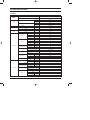
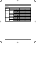
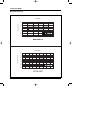
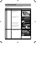
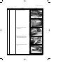
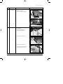
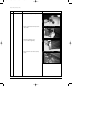
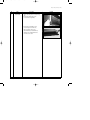
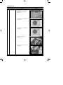
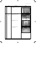
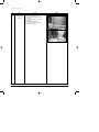
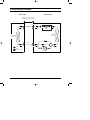
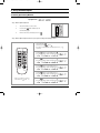
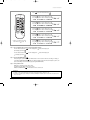
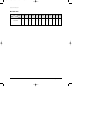
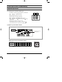
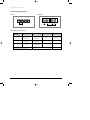
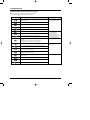
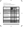
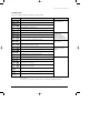
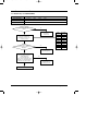
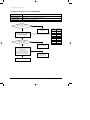
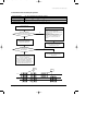
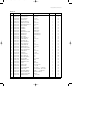
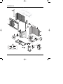
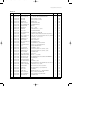
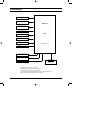
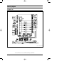
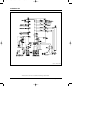
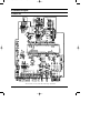
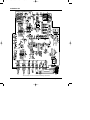
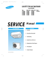
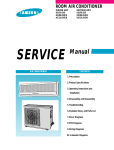
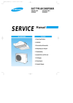
DB98_22254A(1)_CO
05/2/22 1:14 AM
Page 2
DUCT TYPE AIR CONDITIONER
INDOOR UNIT
OUTDOOR UNIT
DH094EAM
UH094EAMC
SERVICE
AIR CONDITIONER
Manual
CONTENTS
1. Product Specifications
2. Disassembly and Reassembly
3. Refrigerating Cycle Diagram
4. Set Up the Model Option
5. Control Specification &
5. Troubleshooting
6. Exploded Views and Parts List
7. Block Diagram
8. Wiring Diagram
9. Schematic Diagram
DB98_22254A(1)_1
05/2/21 10:53 PM
Page 1
1. Product Specifications
1-1 Table
INDOOR UNIT
DH094EAM
OUTDOOR UNIT
UH094EAMC
MODEL
BTU/h
32,000
W
9,400
BTU/h
34,800
Cooling
Capacity
Heating
W
10,200
ø/V/Hz
1/220~240/50
Cooling
W
3,550
Heating
W
3,300
Cooling
A
15.9
Heating
A
15.2
H.H
r.p.m
1,170
Power Supply
Power Input
Running
Current
Hi
r.p.m
1,020
Mid
r.p.m
870
Low
r.p.m
720
H.H
m /min
27
Fan Speed
3
Hi
m /min
23
Mid
m3/min
20
Low
m /min
16
Cooling(Hi)
dB(A)
42
Heating(Hi)
dB(A)
3
Air Flow
Indoor Unit
Noise Level(Hi)
(Sound Pressure)
Heat Exchanger
3
Slit
Row x Stages x Fin pitch
3 x 12 x 1.5mm
Type
Sirocco
Fan
Dimensions
Weight
Motor Output
W
157
H
mm
260
W
mm
1,340
D
mm
600
Net / Gross
kg
43 / 51
Hi
r.p.m
930
Fan Speed
Low
r.p.m
360
m3/min
67
Cooling(Hi)
dB(A)
63
Heating(Hi)
dB(A)
64
Air Flow(Hi)
Noise Level
(Sound Pressure)
Outdoor Unit
Type
Propeller
Fan
Motor Output
W
Type
Model
Motor Output
Protection
122
Rotary
NN40VAAMT
Compressor
Samsung Electronics
42
Type
kW
2.7
Internal
1
DB98_22254A(1)_1
05/2/21 10:53 PM
Page 2
Table(cont.)
MODEL
INDOOR UNIT
DH094EAM
OUTDOOR UNIT
UH094EAMC
Type
R410A
Charge
g
1,750
Adding Charge
g/m
60
Refrigerant
Control
Outdoor Unit
Elec.Expansion Valve
Type
Louver
Row x Stages x Fin pitch
2 x 36 x 1.5
Heat Exchanger
H
mm
798
W
mm
880
D
mm
310
Net / Gross
kg
74 / 82
Liquid
mm(inch)
9.52(3/8")
Gas
mm(inch)
15.88(5/8")
Dimensions
Weight
Pipe O.D Size
Piping
Connection Method
Flare
Height
m
Max.15
Pipe Length
m
Max.30
Between
2
Samsung Electronics
DB98_22254A(1)_1
05/2/21 10:53 PM
Page 3
1-2 Dimensions
1-2-1 Indoor Unit
(Unit : mm)
Samsung Electronics
3
DB98_22254A(1)_1
05/2/21 10:53 PM
Page 4
Product Specifications
1-2-2 Outdoor Unit
798
(Unit : mm)
880
0
31
4
Samsung Electronics
DB98_22254A(1)_1
05/2/21 10:53 PM
Page 5
1-3 Pressure Graph
■ DH094EAM / UH094EAMC
Cooling Mode
10.0
Low Pressure (kgf/cm2G)
9.5
9.0
8.5
8.0
7.5
7.0
6.5
6.0
5.5
15
20
25
30
35
40
45
Heating Mode
37.0
High Pressure (kgf/cm2G)
35.0
33.0
31.0
29.0
27.0
25.0
23.0
21.0
19.0
17.0
15.0
-15
Samsung Electronics
-10
-5
0
5
10
15
20
25
30
5
DB98_22254A(1)_1
05/2/21 10:53 PM
Page 6
2. Disassembly and Reassembly
Stop operation of the air conditioner and remove the power cord before repairing the unit.
2-1 Indoor Unit
No
Parts
1
Filter-Pre
Procedure
Remark
1) Disassemble 2 screws of indication part
and then assemble the direction of
2 Plate-Handle places by use of screw
as shown in 2).
2) Turn the Plate Handle by hand when
removing the Filter-Pre.
3) When pulling the Filter-Pre handle,
the Filter-Pre can be assembled.
✳ Be sure to remove the cushion on the
marked part after initial installation.
(It cause the damage of noise).
2
6
Blower & Duct
1) After disassembling 9 places indicating
screws, detach Ass'y Cover Bottom.
Samsung Electronics
DB98_22254A(1)_1
05/2/21 10:54 PM
Page 7
Disassembly and Reassembly
No
Parts
Procedure
Remark
2) Disassemble 6 indicating screws.
3) Detach the Sensor Holder from the
Ass'y Fan Case.
4) Detach from Ass'y Control In the
capacitor connection wire between the
Motor-Fan in and housing Connector.
5) Detach the Ass'y Blower and Duct from
the set.
Samsung Electronics
7
DB98_22254A(1)_1
05/2/22 2:44 AM
Page 8
Disassembly and Reassembly
No
Parts
3
Control In
Procedure
Remark
1) After disassembling 1 indicating screw,
detach the Cover-Control.
2) Detach the Motor-Fan in and Sensor
Connector connected to PCB.
3) Disassemble 2 indicating screws.
(arrow mark)
4) Hold the Ass'y Control In by hand to lift up
a little and then release the status of
hanging on the hanging slot.
8
Samsung Electronics
DB98_22254A(1)_1
05/2/21 10:55 PM
Page 9
Disassembly and Reassembly
No
Parts
Procedure
4
Drain Pan
1) Disassemble 4 indicating screws to
detach Ass'y Drain Pan.
(2 screws each at left and right side)
5
Evaporator
✳ Work is possible when disassembling the
Ass'y Drain Pan.
Remark
1) Disassemble 8 indicating screws.
(4 each at left and right side)
2) Disassemble 6 indicating screws.
3) Disassemble 5 indicating screws.
✳ It is possible at the status of No.3 Ass'y
Control In disassembly at the time.
Samsung Electronics
9
DB98_22254A(1)_1
05/2/21 10:55 PM
Page 10
Disassembly and Reassembly
No
Parts
Procedure
Remark
4) After disassembling 4 indicating screws.
5) Pull the Cabinet-Side LF, RH by hand to
disassemble.
6) Separate 4 indicating screws.
(2 each at left and right side)
7) Detach it from the set if the Ass'y-Evap
pull up.
10
Samsung Electronics
DB98_22254A(1)_1
05/2/21 10:55 PM
Page 11
Disassembly and Reassembly
No
Parts
6
Holder Outlet
Procedure
Remark
✳ When connecting canvas to the discharge
side.
1) Disassemble 4 indicating screws.
(2 each at left and right side)
2) Disassemble 12 indicating screws.
(6 each at upper and lower side)
✳ After connecting canvas to the
disassembled Ass'y Holder Outlet 2),
attach the Ass'y Holder Outlet to the
set in the reverse order.
Samsung Electronics
11
DB98_22254A(1)_1
05/2/21 10:55 PM
Page 12
2-2 Outdoor Unit
No
Parts
1
Common Work
Procedure
Remark
1) Loosen the fixing screws and detach the
Cover Control.
2) Detach the connection wire from the
Terminal Block.
3) Loosen the fixing screws and detach the
Upper Cabinet.
4) Loosen the fixing screws and detach the
Front Cabinet.
5) Loosen 2 screws and pull up the
Control Box.
6) Detach the terminal cover and detach the
Comp lead wire.
12
Samsung Electronics
DB98_22254A(1)_1
05/2/21 10:55 PM
Page 13
Disassembly and Reassembly
No
Parts
Procedure
Remark
7) Loosen the fixing screws and detach the
Cabinet Side.
2
Fan
&
Motor
1) Loosen the fixing bolt and detach
the Fan.
2) Loosen 4 fixing bolts to detach
the Motor.
3) Loosen 4 fixing bolts to detach
the Bracket Motor.
Samsung Electronics
13
DB98_22254A(1)_1
05/2/21 10:55 PM
Page 14
Disassembly and Reassembly
No
Parts
3
Heat Exchanger
&
Compressor
14
Procedure
Remark
1) Release the refrigerant at first.
2) Disassemble the inlet and outlet pipe
by welding.
3) Loosen the fixing screws of the Heat
Exchanger.
4) Detach the Heat Exchanger.
5) Loosen four bolts of the Compressor.
6) Detach the Compressor.
Samsung Electronics
DB98_22254A(1)_1
05/2/21 10:55 PM
Page 15
3. Refrigerating Cycle Diagram
Indoor Unit
Outdoor Unit
❋ Allowable pipe length : Max. 30m
❋ Allowable drop distance : Max. 15m
3-Way valve
Liquid pipe
Filter
Filter
Expansion
valve
Heat
Exchanger
(Condenser)
Heat
Exchanger
(Evaporator)
Gas pipe
3-Way valve
Cooling
Heating
Gas leak check point
Samsung Electronics
4-Way valve
Accumulator
Muffler
Compressor
15
DB98_22254A(1)_1
05/2/21 10:58 PM
Page 16
4. Set Up the Model Option
4-1 Setting Option Setup Method
ex) Option No. :
Step 1 : Enter the Option Setup mode.
1st
Take out the batteries of remote control.
2nd
Press the temp.
button simultaneously and
insert the battery again.
3rd
Make sure the remote control display shown as
.
Step 2 : Enter the Option Setup mode and select your option according to the following procedure.
1
The default value is
Otherwise, push the
.
button to
.
Every time you push the button, the display panel reads
or
repeatedly.
1
2
Push the
2
3
4
button to set the display panel to
.
Every time you push the button, the display panel reads
...
repeatedly.
3
Push the
button to set the display panel to
.
Every time you push the button, the display panel reads
...
repeatedly.
5
6
4
Push the
button to set the display panel to
.
Every time you push the button, the display panel reads
...
repeatedly.
5
Push the
button to set the display panel to
.
Every time you push the button, the display panel reads
...
repeatedly.
✳ Setting is not required if you must
a value which has a
default.
16
6
Push the
button to set the display panel to
.
Every time you push the button, the display panel reads
...
repeatedly.
Samsung Electronics
DB98_22254A(1)_1
05/2/21 11:02 PM
Page 17
Set Up the Model Option
7
Press
button, then the default value is
.
8
Push the
button to set the display panel to
.
Every time you push the button, the display panel reads
...
repeatedly.
7
8
9
9
Push the
button to set the display panel to
.
Every time you push the button, the display panel reads
...
repeatedly.
10
11
10
Push the
12
button to set the display panel to
.
Every time you push the button, the display panel reads
...
repeatedly.
11
Push the
button to set the display panel to
.
Every time you push the button, the display panel reads
...
repeatedly.
12
✳ Setting is not required if you must
a value which has a
default.
Push the
button to set the display panel to
.
Every time you push the button, the display panel reads
...
repeatedly.
Step 3 : Upon completion of the selection, check you made right selections.
Press the Mode Selection key,
to set the display part to and check the display part.
The display part shows
.
Press the Mode Selection key,
The display part shows
to set the display part to
and check the display part.
.
Step 4 : Pressing the ON/OFF button (
)
When pressing the operation ON/OFF key with the direction of remote control for unit, the sound ''Ding'' or ''Diriring'' is
heard and the OPERATION ICON( ) lamp of the display is flickering at the same time, then the input of option is completed. (If the diriring sound isn't heard, try again pressing the ON/OFF button.)
Step 5 : Unit operation test-run
First, Remove the battery from the remote control.
Second, Re-insert the battery into the remote control.
Third, Press ON/OFF button( ) with the direction of remote control for set.
• Error Mode
1st If all lamps of indoor unit are flickering, Plug out, plug in power plug again and press ON/OFF key to retry.
2nd If the unit is not working properly or all lamps are continuously flickering after setting the option code, see if the correct option code is
set up for its model.
Samsung Electronics
17
DB98_22254A(1)_1
05/2/21 11:02 PM
Page 18
Set Up the Model Option
■ OPTION ITEMS
REMOTE
CONTROL SEG1
SEG2
SEG3
SEG4
SEG5
SEG6
SEG7
SEG8
SEG9
1
5
4
4
2
1
E
0
SEG10 SEG11 SEG12
MODEL
DH094EAM
18
0
0
0
0
Samsung Electronics
DB98_22254A(1)_1
05/2/21 11:02 PM
Page 19
5. Control Specification & Troubleshooting
5-1 Operation Specification
5-1-1 Tracking process marked on display part
4-1-1
• Left numeral is an address that outdoor unit transfers communication.
-
-
-
... -
Left
Right
(Calling indoor unit)
4-1-1
• Right numeral marks address that is answered.
4-1-1
• During the tracking, left calls indoor unit through
- and checks. At this time
... connected indoor unit set on " " and the indoor unit set
address
marked on right.
Right side mark is marked by when left side is
DISPLAY PART (DS1)
.
(If SW02(MAIN) that set indoor unit address is controlled to "
indoor unit number marked on outdoor unit is marked by "
",
".)
5-1-2 Option set part for Outdoor unit PCB
Data display part
KEY
Setting switch for indoor unit
installation numbers
Setting switch for indoor unit installation numbers
Counts of Indoor
Unit Installation
1
2
3
4
5
6
7
8
9
10 11 12 13 14 15
Numbers
of the switch
1
2
3
4
5
6
7
8
9
A
B
C
D
E
F
● Example : When the installed indoor unit is one, control the arrow of switch
forward to ‘0’ or ‘1’ as figure.
Samsung Electronics
19
DB98_22254A(1)_1
05/2/21 11:02 PM
Page 20
Control Specification & Troubleshooting
5-1-3 Setting Up Option Switches
■ KEY
■ Display
DIS 1
K1
K2
K3
DIS 2
K4
RESET DISPLAY
MODE
SEG1
CHECK
MODE
SEG2
ITEM No.
SEG3
SEG4
CURRENT DATA DISPLAY
■ Summary of KEY functions
Function
K4
K3
K2
K1
Number
(Displayed on SEG 3, 4) (Displayed on SEG 3, 4) (Displayed on SEG 3, 4)
(Displayed
on
SEG
3,
4)
of press times
1
Adding refrigerant at
heating mode
Adding refrigerant at
cooling mode
Reset
Displays data
2
Test operation at
heating mode
Test operation at
cooling mode
-
-
3
End
Pump Down for recovery
of refrigerant
-
-
4
-
End
-
-
✳ Use the K1 only for heat pump models.
20
Samsung Electronics
DB98_22254A(1)_1
05/2/21 11:03 PM
Page 21
5-2 Troubleshooting
5-2-1 Wired remote controller display error occurring
■ If an error occurs,
is displayed on the wired remote controller.
■ If you would like to see an error code, press the Test button.
Display
Description
Compressor down due to protection control of the discharge
temperature sensor
Remarks
Error about protection
control of the outdoor unit
Control due to the condenser temperature sensor when cooling mode
Error of the low pressure switch (Protection control)
Reverse phase error (Protection control)
In removing frost
Error of discharge temperature sensor (Open/Short)
Error about the outdoor unit
sensor (Open/Short)
Detection during the
operation of the indoor unit
(sensing and sending errors into
the communication data)
- System down caused by communication error after completion of
- tracking
Communication and the indoor
unit errors
Error of the outdoor temperature sensor (Open/Short)
Error of condensor temperature sensor (Open/Short)
- Mismatching of the indoor unit numbers set with those
- communication after completion of 5 times tracking
Error of temperature sensor in the indoor unit (Open/Short)
Self-diagnosis of the indoor and
outdoor unit
Error of the heat exchanger sensor in the indoor unit (Open/Short)
Error of electronic expansion valve open in the outdoor unit
(when it is detected more than once)
Error of electronic expansion valve close in the outdoor unit
(when it is detected more than once)
Error of communication between the indoor unit and the wired
remote controller
Wired remote controller errors
Master wired remote controller ↔ Slave wired remote controller
COM1/COM2 Cross-installed error
Error of setting option for wired remote controller COM2
Samsung Electronics
21
DB98_22254A(1)_1
05/2/21 11:04 PM
Page 22
Control Specification & Troubleshooting
5-2-2 LED Display on the receiver & display unit
■ ● If an error occurs during the operation, an LED flickers and the operation is stopped except the LED.
■ ● If you re-operate the air conditioner, it operates normally at first, then detect an error again.
■ ● If you turn off the air conditioner when the LED is flickering, the LED is also turned off.
■ LED Display
LED lamp display
Concealed Type
Error type
Blue
Red
Standard Type
Remarks
Power reset
Error of temperature sensor
in the indoor unit (Open/Short)
Error of heat exchanger sensor
in the indoor unit
Error of the outdoor temperature sensor
Error of the condensor temperature sensor
Error of the discharge temperature sensor
1. No communication for 2 minutes between indoor units
(Communication error for more than 2 minutes)
2. Indoor unit receiving the communication error from
outdoor unit
3. Outdoor unit tracking 3 minutes error
4. When sending the communication error from outdoor unit,
the mismatching of the communication numbers and
installed numbers after completion of tracking.
(Communication error for more than 2 minutes)
1. Indoor unit error
(Display is unrelated with
operation)
2. Outdoor unit error
(Display is unrelated with
operation)
Communication error between indoor units
1. Error of electronic expansion valve close
2. Error of electronic expansion valve open
3. 2'nd detection of high temperature cond
4. 2'nd detection of high temperature discharge
5. Error of reverse phase
6. Compressor down due to 6'th detection of freezing
Detection of the float switch
Error of setting option switches for optional accessories
EEPROM error
EEPROM option error
: On
22
: Flickering
: Off
Samsung Electronics
DB98_22254A(1)_1
05/2/21 11:05 PM
Page 23
Control Specification & Troubleshooting
5-2-3 Outdoor Unit
If an error occurs during the operation, it is displayed on the outdoor unit PCB.
Display
Explanation
High temperature of Discharge (Protection control)
Remark
Error about protection
control of outdoor unit
High temperature of outdoor heat exchanger (Protection control)
Reverse phase error (Protection control)
COMP DOWN to protect being frozen
In removing frost
Error of Discharge TEMP sensor (OPEN/SHORT)
Errors about outdoor unit sensor
(OPEN/SHORT)
Detection during the
operation of indoor unit
(Sensing and sending errors
into the communication data)
System Down caused by communication error after
completion of tracking
Communication and
indoor unit errors
Error of OUT TEMP sensor (OPEN/SHORT)
Error of temperature sensor in outdoor heat exchanger (OPEN/SHORT)
Mismatching of the indoor unit numbers set with those
communicated after completion of tracking
Error of float switch in indoor unit
Error of setting option switches for optional accessories
x
OPEN/SHORT error of room sensor in indoor unit
x
OPEN/SHORT error of eva in sensor in indoor unit
x
EEPROM option error
x
Error of fan starting
Self-diagnosis of indoor and
outdoor unit (x:indoor unit
address)
Displays of operating status
Open error of electronic expansion valve in outdoor unit
(Detected once or more times)
Close error of electronic expansion valve in outdoor unit
(Detected once or more times)
Flicker
Below -5°C when cooling (Outdoor temperature)
Flicker
Over 30°C when heating (Outdoor temperature)
K1, K2, K3, K4,
K5 Flicker
The order of priority : E1 → E2 → E3 → E5 → P0 → P1 → P4 → P5 → P9 → t1 → t2 → t3 → tu → to → G4 → G5 → E3 → qx → rx → vx →
K1, K2, K3, K4, K5
The order of priority : - In case that the same error displays from multi-indoor units, the one having the faster address has the priority.
Samsung Electronics
23
DB98_22254A(1)_1
05/2/21 11:05 PM
Page 24
5-3 Sequence for trouble diagnosis
5-3-1 Outdoor temp. sensor(OPEN/SHORT)
Outdoor unit display
Er → t1 (Outdoor temp. sensor OPEN/SHORT error)
(Operation)
Indoor unit display
How to determine
Reason of error
(Timer)
(Airflow)
(Filter)
Disconnection and short of outdoor temp. sensor
Disconnection or leak of applied sensor
Does the out temperature
sensor connected to PCB?
(CN41)
No
Reoperation
after connect to
connector PCB
Yes
Measure the resistance value
between two terminals after
separating the out temp. sensor
connector from PCB
At this time, Is largely
deviate the resistance value from side
table value?
Yes
Resistance
(kΩ)
70
2.2
60
3.0
50
4.2
40
5.8
30
8.3
20
12.1
10
18.0
0
27.3
-10
43.0
Outdoor unit thermistor
is defective(replace)
No
Check the out temp.
sensor is normal or not by use of
out data display part
➞ Check the temp. data is
normal or not after pressing K4 3 times.
At this time, is occurred the difference
between the out temp. and data?
Temp.
(˚C)
No
PCB and sensor are normal.
To perform the test
operation by use of K2
Yes
Reoperation after PCB replacement
24
Samsung Electronics
DB98_22254A(1)_1
05/2/21 11:05 PM
Page 25
Control Specification & Troubleshooting
5-3-2 Outdoor heat exchanger temp. sensor error(OPEN/SHORT)
Outdoor unit display
Er → t2 (Outdoor heat exchanger temp. sensor error(OPEN/SHORT)
(Operation)
Indoor unit display
How to determine
Reason of error
(Timer)
(Airflow)
(Filter)
Disconnection and short of outdoor heat exchanger temp. sensor
Disconnection or leak of Applied sensor
Does the out heat exchanger
temp. sensor connected to PCB?
(CN41)
No
Reoperation
after connect to
connector PCB
Yes
Measure the resistance value
between two terminals after separating
the out heat exchanger temp.
sensor connector from PCB
At this time, Is largely
deviate the resistance value from side
table value?
Yes
Yes
Resistance
(kΩ)
70
2.2
60
3.0
50
4.2
40
5.8
30
8.3
20
12.1
10
18.0
0
27.3
-10
43.0
Outdoor heat exchanger
temp. is defective(replace)
No
Check the out temp.
sensor is normal or not by use of
out data display part
➞ Check the temp. data is
normal or not after pressing K4 2 times.
At this time, is occurred the difference
between the out temp. and data?
Temp.
(˚C)
No
PCB and sensor are
normal.
To perform the test
operation by one of K2
Reoperation after PCB replacement
Samsung Electronics
25
DB98_22254A(1)_1
05/2/21 11:05 PM
Page 26
Control Specification & Troubleshooting
5-3-3 Outdoor discharge temp. sensor error(OPEN/SHORT)
Outdoor unit display
Er → t3 (Outdoor discharge temp. sensor OPEN/SHORT error)
(Operation)
Indoor unit display
How to determine
Reason of error
(Timer)
(Airflow)
(Filter)
Disconnection and short of outdoor discharger temp. sensor
Disconnection or leak of Applied sensor
Does the outdoor discharge
temp. sensor connected to PCB?
(CN42)
No
Reoperation
after connect to
connector PCB
Yes
Measure the resistance value
between two terminals after separating
the outdoor discharge temp.
sensor connector from PCB
At this time, Is largely
deviate the resistance value from
side table value?
Yes
Yes
Resistance
(kΩ)
130
8.9
120
11.2
100
18.5
80
32
60
59
25
200
20
242
10
362
0
553
Outdoor heat exchanger
temp. is defective(replace)
No
Check the out temp.
sensor is normal or not by use of out
data display part
➞ Check the temp. data is
normal or not after pressing K4 1 times.
At this time, is occurred the difference
between the out temp. and data?
Temp.
(˚C)
No
PCB and sensor are normal.
To perform the test
operation by use of K2
Reoperation after PCB replacement
26
Samsung Electronics
DB98_22254A(1)_1
05/2/21 11:05 PM
Page 27
Control Specification & Troubleshooting
5-3-4 Communication error during the operation
Outdoor unit display
Er → E1 (Communication error during the operation)
(Operation)
Indoor unit display
How to determine
Reason of error
(Timer)
(Airflow)
(Filter)
Disconnection and short of communication lines
Communication error between the indoor unit and outdoor unit.
Check the display after
pressing the reset key on outdoor PCB
Multi type
After 2 minutes, check if PCB address
setting of indoor unit displayed the
communication error among indoor units are
overlapped or not.
(If the indoor unit address is overlapped, the
communication error is occurred.)
- In this case, the communication error is
occurred to over two indoor units set
wrong.
No
When tracking, is there any
indoor answer from display part?
Yes
Measure the 2 lines of outdoor side
by scope after removing the
communication line connecting from
outdoor unit to indoor unit.
If address is not fault
exchange the indoor unit PCB after
communication line check.
At this time, is the voltage
between lines rectangular wave over DC±0.7V
like below figure?
No
Yes
Replace PCB after checking
the outdoor unit communication line
and connector
After connecting again the communication
line connecting from outdoor unit to indoor unit,
remove the communication
connector on indoor unit PCB, and find the
indoor unit preventing communication
through connecting the communication
connectors each by each, and then replace
the indoor unit PCB after line check.
Good
Bad
+0.7V
-0.7V
Samsung Electronics
27
DB98_22254A(1)_1
05/2/21 11:05 PM
Page 28
Control Specification & Troubleshooting
5-3-5 Communication error between indoor and outdoor after initial power input.
Outdoor unit display
Er → E2 (Tracking error)
(Operation)
Indoor unit display
How to determine
Reason of error
(Timer)
(Airflow)
(Filter)
Mismatching the communicating indoor unit and setting switch indoor numbers When outdoor tracking
Communication error between the indoor unit and outdoor unit, and installation number switch
setting miss
Check the setting value of
indoor unit installation number setting
switch of outdoor PCB and actual indoor unit
installation numbers
Is equal indoor unit actual
installation number and installation
number setting switch?
If the indoor unit number installed is one, set the
outdoor unit switch forward to "0", "1"
➞ "0" and "1" spell the connection of an indoor unit.
No
Yes
After setting the indoor unit installation setting
number switch correctly, re-perform the
tracking by pressing the reset key K3 of
outdoor unit PCB
Press the reset key K3 of outdoor unit
PCB and check the display to check the
number of indoor units answering to the
tracking
When tracking, is there any
indoor answer from display part?
Yes
To measure the 2 lines of outdoor unit side by
use of scope after removing the communication
line connecting from outdoor unit to indoor unit
At this time, is the voltage
between lines rectangular wave over
DC±0.7V?
Yes
No
Multi type
After 2 minutes, check if PCB address setting
of indoor unit displayed the communication error
among indoor units is overlapped or not .
(If the indoor unit address is overlapped, the
communication error is occurred.)
- In this case, the communication error is
occurred to over two indoor units set wrong
If address is not fault
exchange the indoor unit PCB after
communication line check.
After connecting again the communication line
connecting from outdoor unit to indoor unit,
check this communication is reverse or not,
and if there is no fault, find the indoor unit
preventing communication through connecting
indoor units each by each, and then
exchange the indoor unit PCB after line check
28
Samsung Electronics
DB98_22254A(1)_1
05/2/21 11:05 PM
Page 29
Control Specification & Troubleshooting
5-3-6 Indoor float switching error
Outdoor unit display
Er → E3 (Indoor float switching error )
(Operation)
Indoor unit display
How to determine
(Timer)
(Airflow)
(Filter)
The status continues over 1 minute that indoor unit float switch is opened.
The rising of water level of drain pan due to the disorder of indoor unit drain pump,
Reason of error
the badness of detection sensor
Is the resistance value ∞
when measuring the resistance value
of two terminal after taking out the floating
switch connector connected to indoor
unit PCB? (Open status)
No
Re-assembly the floating switch
connector and perform the reset of
outdoor power(Required the reset of
indoor unit power)
Yes
Is the same error occurred?
No
Yes
Is much the water of drain pan ?
Replace the indoor unit PCB
Yes
No
Normal operation
Reset the indoor unit power
and check the drain pump operation
Check the floating switch is bad.
Reset the indoor unit
power after replace
No
Does the drain pump operate?
Yes
Is the terminal voltage
of drain pump PCB about
AC220V?
Does the water level decrease?
No
No
Yes
Yes
Replace the drain pump
Replace the indoor unit PCB
Normal operation
Replace the drain pump
Samsung Electronics
❋ Note : E3 error should be released when
indoor unit power is reset.
29
DB98_22254A(1)_1
05/2/21 11:05 PM
Page 30
6. Exploded Views and Parts List
6-1 Indoor Unit
1
2
19
5
19-2
13
19-3
18
19-6
5-5
19-1
5-6
19-4
5-3
19-5
5-4
5-8
20
5-9
5-7
12
5-1
17
5-2
10
9
21
4
23
11
8
22
14
15
7
22-1
22-2
16
3
6
You can search for the updated part code
number through the ITSELF.
URL : http://itself.sec.samsung.co.kr
30
Samsung Electronics
DB98_22254A(1)_1
05/2/21 11:05 PM
Page 31
Exploded Views and Parts List
■
Parts List
No.
Code No.
Description
1
DB63-00076A
COVER-TOP
2
DB63-00074A
3
DB94-00022A
4
Specification
Q'TY
SA / SNA
SGCC-M T0.8
1
SA
COVER-CASE DUCT
SGCC-M T0.8
1
SA
ASS'Y-DRAIN PAN
ASS'Y, BLK
1
SA
DB61-00099A
CASE-BOTTOM
SGCC-M, T0.8
1
SA
5
DB94-00023C
ASS'Y-BLOWER DUCT
ASS'Y
1
SA
5-1
DB64-00071A
PANEL-DUCT HOLDER
SGCC-M, T1.2
1
SA
5-2
DB61-00155A
BRACKET-MOUNT MOTOR
SGCC-M, T2.0
1
SA
5-3
DB90-00121A
ASS'Y-CASE FAN
ASS'Y
2
SA
5-4
DB67-00046A
BLOWER-LF
SGCC-M, ø175
1
SA
5-5
DB67-00046B
BLOWER-RH
SGCC-M, ø175
1
SA
5-6
DB31-00025E
MOTOR-FAN
OSME-1204 SAC
1
SA
5-7
DB61-00499A
BRACKET-MOTOR GUIDE
SGCC-M, T1.6
1
SA
5-8
DB69-60012A
BAND-MOTOR R
SBHG1T1.6x13x105
2
SA
5-9
DB69-60013A
BAND-MOTOR L
SBHG1T1.6x13x105
2
SA
6
DB90-00117A
ASS'Y-CABI LF
ASS'Y
1
SA
7
DB90-00119C
ASS'Y-CABI INLET LF
ASS'Y
1
SA
8
DB70-00026B
PLATE-HANGER LF
SGCC-M, T2.0
1
SA
9
DB96-03152C
ASS'Y-EVAP UNIT
ASS'Y
1
SA
10
DB90-00120C
ASS'Y-CABI INLET RH
ASS'Y
1
SA
11
DB90-00118A
ASS'Y-CABI SIDE RH
ASS'Y
1
SA
12
DB70-00027B
PLATE-HANGER RH
SGCC-M, T2.0
1
SA
13
DB64-00121A
CABINET-SIDE RH B
SGCC-M, T0.8
1
SA
14
DB90-00113A
ASS'Y-HOLDER OUTLET
ASS'Y
1
SA
15
DB90-00114A
ASS'Y-COVER BOTTOM
ASS'Y
1
SA
16
DB71-00019A
PLATE-HANDLE
SGCC-M, T1.2
2
SA
17
DB74-00006A
FILTER-PRE
PE, 36x40
1
SA
18
DB63-01021A
COVER-CONTROL
SGCC-M, T0.8
1
SA
19
DB93-01616K
ASS'Y-CONTROL IN
ASS'Y
1
SNA
19-1
DB90-00116A
ASS'Y-CASE CONTROL
ASS'Y
1
SA
19-2
DB93-00849R
ASS'Y-PCB MAIN
LSP, PCB ASS'Y
1
SA
19-3
DB65-00004H
TERMINAL-BLOCK 6P
DAF-6P
1
SA
DB65-00169A
TERMINAL-BLOCK 6P
DAF-6P
1
SA
19-4
2301-001378
C-FILM
3.5µF/450VAC
1
SA
19-5
DB26-10065C
TRANS-POWER
DC17 AC230V 50Hz
1
SA
19-6
DB61-40291B
HOLDER-WIRE
PP, T2.0, BLK
2
SNA
20
DB61-00190A
SUPPORTER-HANGER
-, SGCC-M,T2.0, -, -, -, ADH2400E
1
SA
21
DB67-00111A
DRAIN-SOCKET
DUCT TYPE, NBR, -, BLK, T3.5xL8
1
SA
22
DB97-01904G
ASS'Y-WIRED REMOTE
COMMO, -, -, -, -, Y, MWR-TH00
1
SA
22-1
DB93-01766C
ASS'Y-PCB REMOCON
MWR-TH00, DVM PLUS
1
SA
22-2
DB39-00933A
CONNECT WIRE-COMM2
AWR-TH00
1
SA
23
DB32-00016B
THERMISTOR-ASS'Y
-,-,-,-,ADC-35ZH3
1
SA
Samsung Electronics
31
DB98_22254A(1)_1
05/2/21 11:08 PM
Page 32
6-2 Outdoor Unit
1
19
3
20
14
21
23
15
22
6
5
24
9
4
10-8
25
10-6
11
10-1
10
10-3
10-7
10-5
10-4
10-2
13
12
16
2
17-1
18-1
26
2-1
2-2
18
17
2-3
32
2-4
8
7
Samsung Electronics
DB98_22254A(1)_1
05/2/21 11:08 PM
Page 33
Exploded Views and Parts List
■
Parts List
No.
Code No.
Description
Specification
1
DB63-10213C
COVER-TOP
-,ACRYL,-,-,-,-,-,-
Q'TY
SA/SNA
1
SA
2
DB97-00369A
ASS'Y ACCESSORY
-,-,-,-,18K,24K,-,4WAY-CASSETTE,HEATPUMP
1
SA
2-1
DB60-30010B
NUT-FLARE
HEX,-,5/8-18UNF,-,C3771BD,-
1
SNA
2-2
DB60-30010D
NUT-FLARE
HEX,-,7/18-14UNF,-,C3771BD,-
1
SNA
2-3
DB73-20134A
RUBBER-LEG
RUBBER,-,BLK,-
4
SNA
2-4
DB67-20011A
DRAIN-PLUG OUT
ASH-1814ER,PE,-,WHT,-
1
SNA
3
DB90-01825A
ASS'Y CABINET-FRONT
UH094EAM,APH-H2320
1
SA
4
DB67-50074A
FAN-PROPELLER
AS-1569,-,-
1
SA
5
DB61-20094B
BASE-MOTOR
32K,-,-,-,-,-,SSEC
1
SA
6
DB67-00290A
PARTITION
P-PJT,SGCC-M,T1.0,-,-,-,-,SSEC
1
SA
7
DB95-00571A
ASS'Y-COMP
UH094EAM,NN40VAAMT
1
SA
8
DB95-00505D
ASS'Y HEATER-COMP
UH094EAM,3.2HP, HEATPUMP
1
SA
9
DB31-00260A
MOTOR FAN
OSME-1004SRC,3.2HP(SILHOUETTE),1A,50Hz,200W,230V,1050/400,50Hz,230V,-,-,-
1
SA
10
DB93-03068A
ASS'Y CONTROL OUT
HP,NO,60,-,380V~,50Hz,-,-,R-410A,ROTARY,-,EUROPE,-,220-240V 50Hz,-,-,-,UH094EAM
1
SNA
10-1
DB26-10070F
POWER TRANS
DC17,AC230,-,-,-,DC17,DC0.6A,-
1
SA
10-2
DB65-00112A
TERMINAL BLOCK
-,6P,600V,35A,-,-,-,DVS
1
SA
10-3
DB35-00046A
RELAY-POWER
XMCO-252LBBC,25A
1
SA
10-4
DB90-01264A
ASS'Y CASE-CONTROL OUT
UH070EZM,SSEC,DPM
1
SA
10-5
DB61-01582A
CASE PCB
UH070EZM,ABS,2.5,-,-,BLACK,DPM,5V
1
SA
10-6
2301-001367
C-FILM,LEAD-OTHER
6000nF,+10-5%,450V,BK,58x25x40mm,-
1
SA
10-7
2501-001236
C-OIL
30uF,450V,BK,53x85mm,20.6
2
SA
10-8
DB61-02319A
CLIP-CAPACITOR
UH094EAMC,-,-,-,SSEC
1
SA
11
DB32-00102A
THERMISTOR-OUT
204CT,200K/25,3435K,-20-150,50mA,5V,-,-,SSEC
1
SA
12
DB32-00101A
THERMISTOR-OUT
204CT,200K/25,3435K,-20-150,50mA,5V,-,-,SSEC
1
SA
13
DB93-02919C
ASS'Y PCB MAIN
UH094EAMC,SSEC
1
SA
14
DB90-40176B
ASS'Y COVER-CONTROL
AS-126-/1210,-
1
SA
15
DB64-00862A
CABINET-SIDE RH PAINT
W1-PJT,-,-,-,-,-,SC-97445T,-
1
SA
16
DB62-02868A
INSULATION-SOUND
UH094EAM,GRAY FELT,10,740,342,GRAY,NON FLAMMABILITY,-,-
1
SA
17
DB99-00588A
ASS'Y VALVE 4WAY
UH094EAM,SSEC
1
SA
17-1
DB33-00058A
ASS'Y-SOLENOID VALVE
-,SSEC
1
SA
18
DB97-02975A
ASS'Y VALVE-EXPANSION
UH094EAM,-,-,-,SSEC
1
SA
18-1
DB62-02567K
VALVE EXPAN-COIL
RVPC035B2M3,ASS'Y,30~90pps,33KG,RED,480,O1.4,DC12V,1-2ø
1
SA
19
DB63-00758A
GUARD COND-(PAINT)
P-PJT,SECC-P ,T=1.6,-,-,-,SSEC
1
SA
20
DB61-00821A
GUIDE-SCREEN
AP-L2340,P.E.H 100%,T2.5,1025,770,BLK,-
1
SA
21
DB63-00691A
GUARD FAN
AP-SR2370,HSWR,,,,SC-90073T,460 FAN 3u
1
SA
22
DB96-04497A
ASS'Y COND
UH094EAMC,-
1
SA
23
DB70-00163A
PLATE-COND
MH18VA1,SGCC-M, ,T0.8, ,-, ,-,MULTI-INVERTER
2
SA
24
DB96-03814B
ASS'Y COLLECTOR
ASS'Y COLLECTOR IN,,HEAT PUMP
1
SA
25
DB96-03815B
ASS'Y DISTRIBUTOR
ASS'Y DISTRIBUTOR OUT,HEAT PUMP
1
SA
26
DB90-00887F
ASS'Y BASE OUT
UH094EAMC,SSEC
1
SA
Samsung Electronics
33
DB98_22254A(1)_1
05/2/21 11:08 PM
Page 34
7. Block Diagram
Up and down STEP MOTOR
Room temp. SENSOR
pipe sensor
MAIN PCB
Function display part remote
control receiving part
Option saving control
MICOM
Communication(485comm)
Indoor unit ADDRESS setting part
RMC ADDRESS setting part
485 comm control
Blackout restoring function
Room temp. compensation function
Power source comm wrong
connection prevention function
Central control
Vent fan control
-
34
- Wired remote controller
- Relay
- Central controller
485 comm applied, room temp. compensation
EEPROM option saving and blackout restoring function
Power-comm line misconnection prevention function
Cost saving related sub-option separation between indoor unit communication part
Option part sub-development according to the SVC structure
Samsung Electronics
DB98_22254A(1)_1
05/2/21 11:08 PM
Page 35
8. Wiring Diagram
8-1 Indoor Unit
Code No : DB98-20414A
This Document can not be used without Samsung's authorization.
Samsung Electronics
35
DB98_22254A(1)_1
05/2/21 11:08 PM
Page 36
8-2 Outdoor Unit
Code No : DB98-19361A
This Document can not be used without Samsung's authorization.
36
Samsung Electronics
DB98_22254A(1)_1
05/2/21 11:09 PM
Page 37
9. Schematic Diagram
9-1 Indoor Unit
This Document can not be used without Samsung's authorization.
Samsung Electronics
37
DB98_22254A(1)_1
05/2/21 11:09 PM
Page 38
9-2 Outdoor Unit
This Document can not be used without Samsung's authorization.
38
Samsung Electronics
DB98_22254A(1)_1
05/2/21 11:09 PM
Page 39
MEMO
Samsung Electronics
39
DB98_22254A(1)_1
05/2/21 11:09 PM
Page 40
MEMO
40
Samsung Electronics
DB98_22254A(1)_CO
05/2/21 11:12 PM
Page 1
ELECTRONICS
This Service Manual is a property of Samsung Electronics Co., Ltd.
Any unauthorized use of Manual can be punished under applicable
International and/or domestic law.
© Samsung Electronics Co., Ltd. Feb. 2005.
Printed in China.
Code No. DB98-22254A(1)