1
ESP15
Operating Instruction and Parts Manual
Please read and save these instructions. Read carefully before attempting to assemble, install, operate or maintain the product described.
Protect yourself and others by observing all safety information. Failure to comply with instructions could result in personal injury and/or
property damage! Retain instructions for future reference.
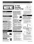
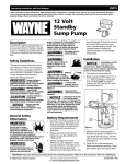
12 Volt
Standby
Sump Pump
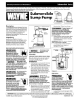
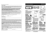
Description
The ESP15 is a battery operated back-up
sump pump. It does not replace a regular
pump. It is designed to provide protection
in the event household electrical power
fails.
Safety Guidelines
This manual contains information that is
very important to know and understand.
This information is provided for SAFETY
and to PREVENT EQUIPMENT PROBLEMS.
To help recognize this information,
observe the following symbols.
Danger indicates
an imminently
hazardous situation which, if not avoided,
will result in death or serious injury.
Warning indicates
a potentially
hazardous situation which, if not avoided,
could result in death or serious injury.
Caution indicates a
potentially
hazardous situation which, if not avoided,
may result in minor or moderate injury.
Do not use to pump
flammable or explosive
fluids such as gasoline, fuel
oil, kerosene, etc. Do not use
in a flammable and/or explosive
atmosphere. Pump should only be used to
pump clear water. Fatal injury and/or
property damage could result.
If the basement has water or
moisture on the floor, do not
walk on wet area until all
SUMP
PUMP
RY
LIA
UXI
Sump A
Pump
been discharged. If electrical power to
the house is lost more than once a
week, consider keeping a spare, fullycharged battery to replace an
exhausted battery for the standby
sump pump.
Installation
Do not expose battery to
sparks or flames as an
explosion or fire could
result.
Installation of this
unit may take
several hours. Before disabling your
main pump, have ready an appropriate
means of evacuating the sump.
Battery
acid is corrosive. Avoid
,,,
yyy
,,,
yyy
,,,
yyy
spilling on skin or clothing.
Eye protection must be worn
when handling the battery.
A check valve
must be used on
the primary sump pump discharge (see
Figure 1)
A ground fault
circuit interrupter is
required.
This pump must only
! NOTICE
be used to pump
clear water. This pump is not designed to
handle effluent, salt water, brine, laundry
discharge or any other application which
may contain caustic chemicals and/or
foreign materials. Pump damage may
occur if used in these applications and
will void warranty.
1. Turn power to main pump off.
!
NOTICE
2. Pump must be installed using 11/4” or
11/2” rigid PVC piping. A check valve
(not included) must be installed
between the ESP’s tee and the main
pump (see Figure 1).
4 inch min.
↔
General Safety
Information
BACKUP
↔
NOTICE
Notice indicates
important
information, that if not followed, may
cause damage to equipment.
!
power is turned off. If the shutoff box is
in the basement, call an electrician.
Remove pump and either repair or
replace. Failure to follow this warning
could result in fatal electrical shock.
All wiring must be
performed by a
qualified electrician.
BATTERY
Battery Requirements
1. Use only a new fully charged 12 volt
deep cycle battery. Electrolyte level
must be checked and maintained in
accordance with manufacturer’s
guidelines.
2. Battery sizes that will fit into the
battery box are 24C, 24VCM, 27C,
27CM and 27F.
3. Battery recharge time will be
different at each installation. Under
normal conditions it will take two to
four days to bring a deep cycle
battery back to full charge after it has
1 inch
min.
Check
valve
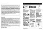
Figure 1
3. Measure and cut discharge pipe so
that back-up pump is a minimum of 1
inch above the main pump. This will
allow main pump to operate normally
(see Figure 1).
4. Check the fit of the components
before permanently attaching. Using
PVC cement, glue tee in place. Note
351201-001 6/99
© 1999 Campbell Hausfeld
1
Operating Instructions And Parts Manual
Installation
(Continued)
the up direction arrow on the tee; the
notch must be to the top or flapper
valve will not work (see Figure 2).
Tee
fitting
Notch
Flapper
valve
locator
tab
Clamp
8. The standby pump’s float switch
should be installed so that it will not
activate until the standby pump’s inlet
is under water. Use the wire ties
provided to secure the float switch
(see Figure 4). Make sure power wires
do not interfere with float switch or
pump inlet.
9. Attach control box to the side of
battery box as shown in Figure 5. Place
battery in box, attach red cable to
positive battery post and black cable
to negative post. Put lid on box and
strap closed.
Battery box bottom
Control
box screw
Standby sump pump
5. Insert flapper valve into tee. Be sure
locator tab is in the notch in tee (see
Figure 2).
BATTER
Y BACKUP
SUMP PUM
P
RY
ILIA
AUX
Sump
Pump
6. Slide clamp onto tee.
7. Insert pump into flapper valve, tilt
pump 30˚. When tilted, side with
power cord should be up (see Figure
3). Tighten clamp around the pump
and flapper valve (see Figure 2).
Correct
Incorrect
30˚
Figure 3
Pump must be
tilted as shown in
Figure 3 to prevent air locking.
On
2 inch
tether
Float
Switch
Wire ties
Standby
sump
pump
inlet
Control box
Figure 5
If cables are
reversed, damage to
the control box or battery could result,
and warranty will be void.
10. Place battery box within six feet of the
sump and a 115 VAC separately fused
outlet. The outlet must be protected
by a ground fault circuit interrupter
(GFCI). The area must also be clean,
dry and well-ventilated.
11. Plug the float switch, pump and
charger into the control box. The
connections are marked on the
control box.
12. Test pump operation by filling the
sump with water while the main
pump is unplugged. If the pump
operates properly, plug the charger
into the GFCI protected outlet to
begin charging the battery.
13. Protect electrical cord from sharp
objects, hot surfaces, oil and
chemicals. Avoid kinking the cord and
replace damaged components
immediately.
Operation
Off
Risk of
electrical shock! Use a
GFCI receptacle to reduce
the risk of fatal electrical
shock.
Cutting the cord or plug will void the
warranty and make the pump
inoperable.
1. After installation, the standby pump
will start when the water level rises
above the depth that the primary
pump should start.
Lead Wires
Figure 2
service, relocate or maintain the pump.
Never touch sump pump, pump motor,
water or discharge piping when pump is
connected to electrical power. Never
handle a pump or pump motor with wet
hands or when standing on wet or damp
surface or in water. Fatal electrical shock
could occur.
2. The control box has a DC charger
designed to shorten the recharging
time of your battery, and to prevent
overcharging. In addition, the control
box has a time delay which keeps the
pump from repeated, short cycles
when it shuts off. This time delay
feature will allow the pump to run
two to three seconds after the switch
reaches the off position.
3. The control box contains a multicolored indicator light. When AC
power is present, the light will
indicate the charging state, and not
reflect actual battery voltage,
particularly with a defective battery.
In order for the indicator light to
provide an accurate reading, steps
“a” through “d” must be followed.
a. Unplug main AC pump and the
charger--a power off alert tone will
sound for 30 seconds.
b. Lift and release the float switch to
activate the standby pump.
c. When the pump stops, read the
test light:
Green: Indicates battery is
charged.
Yellow: Voltage is low,
indicating battery is partially
charged.
Red: Battery is completely
discharged or defective.
1“ min.
d. Plug in charger and main AC
pump.
Figure 4
Always disconnect the
power source before
attempting to install,
2
When AC power is out, and when
pump has been running, the light will
indicate battery status.
ESP15
Operation (Continued)
4. A chirping sound from the control
box will accompany the red light,
indicating that the battery may
require attention or replacement.
Voltage is only an indicator of
battery condition and may not reflect
the true condition of the battery. See
Maintenance for instruction on
assessing battery condition.
5. A single thirty-second tone will sound
when power to the system is
interrupted. The unit will reset
automatically when power is
restored. A three-second tone will
sound every time the pump starts.
Maintenance
Always disconnect the
electrical supply before
attempting to install,
service, relocate or perform any
maintenance. If the power source is out
of sight, lock and tag in the open (off)
position to prevent unexpected power
application. Failure to do so could result
in fatal electrical shock. Only qualified
electricians should repair this unit.
Improper repair could result fatal in
electrical shock.
1. Once a month, check battery
condition.
2. Unplug the wall charger.
3. For batteries with top caps that can
be removed, the electrolyte level
should be checked and filled to
manufacturer’s specifications. The
charge for each cell should be
checked with a hydrometer. A
specific gravity of 1.265 indicates the
battery is at full charge. If the specific
gravity of any of the cells varies more
than .050, the battery should be
replaced.
NOTE: An inexpensive hydrometer
can be purchased at an automotive
parts dealer.
4. Inspect the terminals and clamps for
corrosion and tightness. Clean and
tighten as required.
5. Unplug the main pump and fill sump
with water until back up pump turns
on. Repeat process two times to be
sure pump is operating normally.
6. If pump operates normally, plug
charger into wall outlet, turn on
main pump. If pump fails to operate
normally, see Troubleshooting guide
and correct problem. Repeat step 5.
Troubleshooting Chart
Symptom
Possible Cause(s)
Corrective Action
Pump won’t run
1. Connections not secure
2. Low or defective battery
3. Float switch unable to swing up and
down as needed
4. Defective or blown fuse
1. Check all connections
2. Check battery and replace if low or defective
3. Check that float switch tether is long enough to allow pump to
operate
4. Check internal fuse located inside the control box. Pull the charger
from the wall outlet and remove. If the fuse is blown, replace it with
a 15 amp automotive type fuse
Motor hums but
pump won’t run
1. Defective battery
2. Impeller is locked
1. Check battery and replace if low or defective
2. Unplug pump and check to see if impeller is free to turn. If impeller
is locked, remove the 4 screws on the bottom of the pump to release
the housing around the impeller. Remove the obstruction.
Reassemble pump and reconnect
Pump runs but
pumps very little
or no water
1. Check valve missing or improperly
installed
1. Check to make sure a check valve is installed and functioning
between primary pump discharge and Standby Sump Pump tee
fitting
2. Check for obstruction and clear if necessary
3. Check that pump is rotated 30˚ in tee fitting as shown in Figure 3
4. The impeller housing has a small hole on its side. This hole must be
open for the pump to prime. With the pump unplugged, remove the
4 screws on the bottom of the pump to release the housing around
the impeller. Clean out the hole and replace cover
5. If discharge is too high, a separate line may be required with a lower
discharge height
6. Check battery and replace if low or defective
2. Obstruction in discharge pipe
3. Pump not rotated 30˚
4. Pump air locked
5. Discharge pipe length and/or height
exceeds capacity of pump
6. Low or defective battery
Pump cycles too
frequently
1. Tether length too short on float
switch
2. Main check valve located between the
discharge of the primary pump and
the Standby Sump Pump tee fitting or
the Standby Sump Pump flapper valve
not installed or working properly
1. Tether length should be at least 2”. Adjust if necessary
CAUTION: Ensure tether will swing freely without obstruction
2. Install check valve or repair as required
3
Operating Instructions And Parts Manual
For Replacement Parts, call 1-800-237-0987
Please provide following information:
-Model number
-Serial number (if any)
-Part descriptions and number as shown in parts list
Address parts correspondence to:
Wayne Home Equipment
100 Production Drive
Harrison, OH 45030 U.S.A.
10
Ref.
No. Description
1
9
2
3
8
6
7
Part
Number
Qty.
1
Wire tie
17182-003
4
2
Tee fitting
17233-002
1
3
Battery box/strap
23217-001
1
4
Charger
17220-004
1
5
Control box
30209-001
1
6
Screw - control box
16119-002
4
7
Pump
17218-003
1
8
Flapper valve
17216-001
1
9
Clamp - hose
16044-001
1
10
Float switch
30206-001
1
5
4
Limited Warranty
For one year from the date of purchase, Wayne Home Equipment Division ("Wayne") will repair or replace, at its option, for the original
purchaser any part or parts of its Sump Pumps or Water Pumps (“Product”) found upon examination by Wayne to be defective in
materials or workmanship. Please call Wayne (800-237-0987) for instructions or see your dealer. Be prepared to provide the model
number when exercising this warranty. All transportation charges on Products or parts submitted for repair or replacement must be paid
by purchaser.
This Limited Warranty does not cover Products which have been damaged as a result of accident, abuse, misuse, neglect, improper
installation, improper maintenance, or failure to operate in accordance with Wayne’s written instructions.
THERE IS NO OTHER EXPRESS WARRANTY. IMPLIED WARRANTIES, INCLUDING THOSE OF MERCHANTABILITY AND FITNESS FOR
A PARTICULAR PURPOSE, ARE LIMITED TO ONE YEAR FROM THE DATE OF PURCHASE. THIS IS THE EXCLUSIVE REMEDY AND
ANY LIABILITY FOR ANY AND ALL INDIRECT OR CONSEQUENTIAL DAMAGES OR EXPENSES WHATSOEVER IS EXCLUDED.
Some states do not allow limitations on how long an implied warranty lasts, or do not allow the exclusions or limitations of incidental or
consequential damages, so the above limitations might not apply to you. This limited warranty gives you specific legal rights, and you
may also have other legal rights which vary from state to state.
In no event, whether as a result of breach of contract warranty, tort (including negligence) or otherwise, shall Wayne or its suppliers be
liable for any special, consequential, incidental or penal damages including, but not limited to loss of profit or revenues, loss of use of
the products or any associated equipment, damage to associated equipment, cost of capital, cost of substitute products, facilities, services
or replacement power, downtime costs, or claims of buyer’s customers for such damages.
You MUST retain your purchase receipt along with this form. In the event you need to exercise a warranty claim, you MUST send a
copy of the purchase receipt along with the material or correspondence. Please call Wayne (800-237-0987) for return authorization and
instructions.
DO NOT MAIL THIS FORM TO WAYNE. Use this form only to maintain your records.
MODEL NO._______________ SERIAL NO.__________________________ INSTALLATION DATE_____________
ATTACH YOUR RECEIPT HERE
4