1
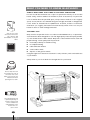
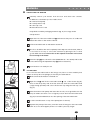
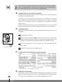
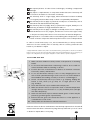
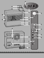
SRE 250
SRE 260
3
MANUEL D'UTILISATION
2
2
GEBRAUCHSANWEISUNG
12
6
BRUGSANVISNING
22
5
INSTRUCCIONES DE USO
32
4
OPERATING MANUAL
42
>
ISTRUZIONI D’USO
52
1
GEBRUIKSAANWIJZING
62
:
INSTRUKCJA OBSŁUGI
72
TR
KULLANIM KILAVUZU
82
3
PAGE PLIANTE
2
FALTBLATT
6
FOLDEUDSIDE
5
HOJA DESPLEGABLE
4
FOLD-OUT PAGE
>
PIEGHEVOLE
1
UITVOUWBLAD
:
WKŁADKA ILUSTRACYJNA
KATLANIR SAYFA
TR
E
E
E
E
E
E
E
E
E
E
E
E
E
E
E
E
E
E
E
E
E
Dear Sir, Madam,
Congratulations with your purchase of the Zibro, the number one brand among
movable heaters. You have purchased a first-class quality product, which will
serve you for many years to come. This, of course, provided you use the heater
correctly. Please read these Directions for Use first, to ensure maximum lifetime
for your Zibro.
Your heater comes with a 24-month manufacturer’s warranty on all defects in
material or workmanship.
We wish you much warmth and comfort with your Zibro.
Yours sincerely,
PVG International b.v.
Customer Service Department
1 READ THE DIRECTIONS FOR USE FIRST.
2 IN CASE OF ANY DOUBT, CONTACT YOUR ZIBRO DEALER.
3 BEFORE YOU START READING, FOLD OUT THE LAST PAGE.
4
42
SRE 250
SRE 260
E
E
E
E
E
E
E
E
E
E
GENERAL DIRECTIONS FOR USE
MAIN COMPONENTS
Below you will find the main steps to be taken for
using your Zibro. For more details, please refer to the
A
Front plate
B
Grid
C
Base plate
4
Lid for removable
MANUAL (pages 45 ff.).
1
2
3
4
5
Remove all packaging materials (Fig. A).
tank
Fill the removable tank 7 (refer to Section B, Fig. D).
Insert the plug into the wall-socket.
Ignite the heater using the
E
Operation panel
F
Handle
G
Removable tank
H
Air filter cap
I
Vent filter
J
Thermostat
K
Plug + cord
L
Information display
key M (refer to Section D).
If required, change the temperature using the adjustment keys
(refer to Section E).
6
Switch off the heater by pressing the
key M.
M
key
N
Childproof lock
O
Adjustment keys
(time and
temperature)
•
The first time you ignite your heater it will smell
like ’new’ for a short time.
•
•
P
TIMER
Q
SAVE key
R
Indicator lights
S
Connection
Store your fuel in a cool and dark place.
Fuel has a limited shelf life. Start every heating
season with renewed fuel.
•
The right quality of fuel will be assured, when you
use Zibro Extra or Zibro Kristal for your heater.
•
If you change to another brand and/or type of
Weektimer
parrafin oil, you must first finish up all the
remaining fuel in the heater.
E
E
E
E
E
E
E
E
E
E
E
E
E
E
E
E
E
E
E
E
4
43
SRE 250
SRE 260
E
E
E
WHAT YOU NEED TO KNOW IN ADVANCE
ALWAYS MAKE SURE THAT THERE IS SUFFICIENT VENTILATION
For each model the minimum size of space is specified in which you can use the
heater safely, without additional ventilation (refer to Section P). If a particular
room is smaller than the specified space, always leave a window or door slightly
ajar (± 2.5 cm). We also recommend doing this in highly insulated or draught-free
rooms and/or at altitudes above 1,500 metres. However, if there is insufficient
ventilation (i.e. oxygen), the heater will automatically switch off. Do not use your
heater in cellars or other underground areas.
THE RIGHT FUEL
Only the use of the
correct fuel will ensure
safe, efficient, and
comfortable use of your
Zibro.
Only use Class C1 paraffin fuel in accordance with BS2869: Part 2, or equivalent.
Your heater has been designed for use with high-quality water-free pure paraffin
oil, such as Zibro Extra or Zibro Kristal. Only fuels of this kind will ensure clean and
proper burning. Lower quality fuel may result in:
E
increased possibility of malfunctioning
E
incomplete burning
E
reduced heater lifetime
E
smoke and/or smells
E
deposits on the grid or mantle
Using the right fuel is therefore essential for safe, efficient, and comfortable use
of your heater.
Always refer to your local dealer for the right fuel for your heater.
A
The fuel cap cover can
be found at the rear of
the heater. This cover
allows you to keep your
hands clean when
opening the fuel tank.
This transportation cap
is packed separately in
the box. Only this cap
ensures trouble-free
transportation of the
heater after use.
Store it well!
4
44
SRE 250
SRE 260
MANUAL
A
E
E
E
E
INSTALLING THE HEATER
1 Carefully remove your heater from the box and check the contents.
In addition to the heater you also need to have:
E a manual fuel pump
E a transportation cap
E a fuel cap cover
E these directions for use
Keep the box and the packaging materials (Fig. A) for storage and/or
transportation.
2 Open the lid of the removable tank 7 and remove the piece of cardboard.
Attach the sticker to the inside of the lid.
3 Fill the removable tank as indicated in Section B.
4 The floor should be firm and completely level. Reposition the heater, when it
is not level. Do not try to correct the situation by placing books or other
goods under the heater. Please refer to the separate instruction in the carton
box for fixing of the heater.
5 Insert the plug K into the wall-socket (220/230 Volts - AC / 50 Hz) and set the
B
correct time using the adjustment keys O (refer to Section C).
6 Your heater is now ready for use.
B
FILLING FUEL
Do not fill the removable tank in the living room, but in a more suitable place
C
(there can always be some spillage). Follow the procedure below:
1 Make sure that the heater is switched off.
2 Open the lid 4 and lift the removable tank 7 out of the heater (Fig. B).
Note: Some drops may leak from the tank. Put down the removable tank
(cap pointing upwards) and screw off the fuel cap using the fuel cap cover
(Fig. C).
D
3 Take the manual fuel pump and insert the smooth, most rigid tube into the
jerrycan. Make sure that it is in a higher position than the removable tank
(Fig. D). Insert the ribbed hose into the opening of the removable tank.
4 Lock the switch button on top of the pump (turn clockwise).
5 Squeeze the pump a few times, until fuel starts flowing into the removable
tank. As soon as this happens, there is no need to press any longer.
4
45
SRE 250
SRE 260
E
E
E
6 Check the removable tank fuel gauge G while filling the tank (Fig. E). Stop
filling by loosening the switch button on top of the pump (turn anti-clockwise), once the gauge indicates that the tank is full. Never overfill the tank,
especially not when the fuel is very cold (fuel expands when it heats up).
empty
full
7 Let the remaining fuel in the pump flow back into the jerrycan and carefully
remove the pump. Carefully screw the fuel cap back on the tank using the
fuel cap cover. After use, re-store the cover at the rear of the heater. Clean
off any spilled fuel.
8 Check whether the fuel cap is straight and tightened properly. Reinstall the
removable tank in the heater (cap down). Close the lid.
C
SETTING THE CLOCK
It is only possible to set the correct time, when the heater is connected to the
clock
temp.
mains and not burning. Use the adjustment keys O to set the time. First press
20
1
set
room
either of the two keys to switch on the function (the CLOCK light and the
information display L will start blinking). Next, set the hours using the key on the
left (Nhour) and the minutes using the key on the right (Mmin). Press once to
increase the value by one step. When you hold down the key, the value will
continue going up, until you release the key again. After approximately 10
F: When the CLOCK
indicator light stops
blinking, the setting has
been locked to the
indicated value.
seconds the blinking will stop and the setting will be locked. 5 Minutes after
switching off the heater M, the information on the display will disappear and the
heater will automatically switch into the stand-by position.
☞
When the heater has been unplugged for more than 10 minutes (or after a
power failure), the time needs to be set again.
k
D
IGNITING THE HEATER
When used for the first time, a new heater may give out a smell for a short while.
You should therefore provide extra ventilation.
Just press the
button M to ignite the heater. The button will start blinking,
indicating that the ignition procedure has started. This will take a short while. Once
clock
temp.
the heater is burning, the
14
19
set
button will remain lit (red). The information display
L will show two numbers. The light next to them indicates that these numbers
room
refer to the temperatures (Fig. G). The actual room temperature is indicated below
ROOM, while the temperature setting is indicated below SET. The latter can be
changed with the adjustment keys (refer to Section E).
G: The required
temperature on the left,
the measured
temperature on the
right.
E
SETTING THE REQUIRED TEMPERATURE
The temperature setting can only be adjusted, when the heater is burning. Use the
adjustment keys O to adjust the temperature. First press either of the two keys to
switch on the function (the TEMP light next to the information display L will start
blinking). Next, adjust the temperature using the key on the right (Mmin) to set
the temperature to a higher setting and the key on the left (Nhour) to lower the
temperature. Press once to increase the value one step. After approximately 10
k
4
46
SRE 250
SRE 260
seconds the light will stop blinking and the setting will be locked (Fig. G).
The available temperature settings range from 6°C minimum to 28°C maximum.
When the heater has been unplugged (or after a power failure), the temperature
will reset to the factory setting of 20°C.
F
USING THE TIMER
The timer allows you to switch on the heater automatically at a preset time.
In order to switch on the timer, the correct time must have been set (refer to
clock
temp.
20
set
Section C) and the heater should be off.
15
room
Follow the procedure below:
1 Press the
button M and then the TIMER key P immediately after that.
The TIMER light on the operation panel E will start blinking.
2 Use the adjustment keys O to set the time at which the heater must ignite.
Use the key on the left (Nhour) to set the hours and the key on the right
(Mmin) to set the minutes (interval of 5 minutes).
key-lock
hour
min.
down
up
3 After approximately 10 seconds the information display will show CLOCK
again and the TIMER indicator light will light up, indicating that the timer
function has been activated (Fig. H).
timer
save
4 The timer will ensure that the room will have been heated to approximately
f
the required temperature at the set time.
☞
H: The TIMER indicator
light indicates that the
timer function has been
switched on.
When you want to switch off the heater and ignite it again with the timer, all
you have to do is press the TIMER key (refer to Section G).
Press the
G
button M once to clear the timer setting.
SWITCHING OFF THE HEATER
There are two ways to switch off the heater.
1 Press the
button M. The information display will show the CLOCK
signal. Within approximately one minute the flame will have extinguished.
2 Press the TIMER key P without pressing the
button, when you want
to switch off the heater and ignite it again with the timer the next time. This
not only switches off the heater, but it also activates the timer function. As
long as the TIMER light and the information display L are blinking, you can
change the required time with the adjustment keys O (refer to Section F).
H
THE INFORMATION DISPLAY
The information display L not only serves as an indicator of the (set) time and
temperature (Sections C, E, and F), it also indicates any malfunctioning of the
heater. The code on the information display tells you what is the matter:
4
47
SRE 250
SRE 260
clock
temp.
0
eset
room
In case of any
malfunctioning the
information display will
tell you what is the
matter.
CODE
INFORMATION
WHAT TO DO
efefeeee-
Temperature within the heater too high.
Cool-down and re-ignite.
0
0
1
1
2
5
6
7
Power interrupted.
Re-ignite the heater.
Faulty thermostat.
Contact your dealer.
Faulty burner thermistor.
Contact your dealer.
Starting problems.
Contact your dealer.
Tipping-over protection.
Re-ignite the heater.
Poor burning.
Contact your dealer.
Room temperature
If necessary,
SRE250: above 28°C.
re-ignite the heater.
SRE260: above 27°C.
e- 8
e- 9
-: -(& blinking
Defective booster.
Contact your dealer.
Air filter dirty; or
Clean filter
Fuel pump dirty.
Contact your dealer.
Out of fuel.
Refill removable tank.
Too little ventilation.
Ventilate better.
FUEL-light)
-: -(& blinking
VENT-light)
k
Always contact your dealer for any malfunctioning not listed above.
AUTOMATIC CLEANING MODE
c ck
t mp.
cl
When te heater has been burning continuously for two hours at its highest
05
set
setting, the burner will automatically start an autoclean procedure. The display
room
will show the autocleaningcode CL.05 running back to CL.00. The procedure takes
5 minutes, during which the heater will burn at its lowest setting, while the burner
autocleans. When the burner is clean again, the heater will automatically switch
back to the highest setting again.
I
CHILDPROOF LOCK
The childproof lock can be used to prevent children accidentally changing the
heater settings. When the heater is burning and the childproof lock is on, the
key-lock
heater can only be switched off. Other functions are blocked then. If the heater
has already been switched off, the childproof lock also prevents accidental
I: When the KEY-LOCK
light lights up, the
childproof lock has been
activated.
ignition of the heater.
Activate the childproof lock by pressing the appropriate key N and holding it down
k
for more than 3 seconds. The KEY-LOCK indicator light will light up (Fig. I),
t
indicating that the childproof lock has been activated. Switch off the childproof lock
by pressing the key N and holding it down for more than 3 seconds once again.
J
save
THE CORRECT USE OF 'SAVE'
The 'SAVE' function allows you to limit the temperature. When this function is
activated, the heater will automatically switch off, when the room temperature
fuel
exceeds the set temperature by 4°C. Subsequently, when the room temperature has
J: When the SAVE light
v heater will
lights up, the
automatically switch on
or off in order to remain
within a specified
temperature range.
4
48
SRE 250
SRE 260
dropped again to the set temperature, the heater will automatically switch on again.
Activate the 'SAVE' setting by pressing the appropriate Q key. The SAVE indicator
light will light up (Fig. J). Switch off the function by pressing the SAVE key once
again.
☞
10
clock
temp.
set
room
Without the 'SAVE' setting your heater will maintain the set temperature by
approximation as well, by adjusting its heating capacity. 'SAVE' is an economy
setting, which you can use when, for instance, you are not present in the room
or to keep it frost-free.
K
THE 'FUEL' INDICATOR LIGHT
When the FUEL indicator light lights up, there is enough fuel left for another 10
minutes of heater use. The count-down of the remaining heating time can be seen
h
in the information display L (Fig. K). Every two minutes an alarm signal is
key-lock
hour
min.
down
up
sounded, warning you to refill the removable tank. If you do not react, the heater
will extinguish by itself. The heater will also sound a warning signal, when it
switches off. The FUEL indicator light will blink, while four lines are blinking in the
timer
information display. You can stop this by pressing the
button M once.
save
fuel
Once the heater has used up all its fuel and extinguished, it will take some time,
K: When the FUEL
indicator light is lit, the
information display will
show the number of
minutes of fuel left in
the tank.
v
after the refill, before the heater is completely ready for use again.
L
THE 'VENT' INDICATOR LIGHT
When the VENT indicator light starts blinking, this is a sign that the room is not
vented sufficiently (Fig. L). If you do not provide additional ventilation, the heater
will switch off automatically after some time.
fuel
If the indicator light continues blinking after extra ventilation, please contact your
dealer.
vent.
M
L: A blinking VENT
indicator light is a sign
that you need extra
ventilation.
M
MAINTENANCE
Switch off the heater and let it cool down, before you start any maintenance
work. Also disconnect the plug from the mains.
Your heater needs hardly any maintenance. It is, however, important that you
clean the air filter cap 8 and the vent filter 9 with a vacuum cleaner and the grid
2 with a damp cloth, both on a weekly basis. Remove the air filter cap
occasionally (Fig. M) and clean it with soapy water. Prior to reinstallation, make
sure that the air filter cap has fully dried.
Regularly inspect the fuel filter as well:
1 Remove the removable tank 7 from the heater and remove the fuel filter
(Fig. N). Some drops may leak from the filter; keep a cloth at hand.
Fuel filter
N
2 Remove the dirt by tapping the fuel filter upside-down against a hard surface.
(Never clean it with water!)
3 Reinstall the fuel filter into the heater.
We recommend that you remove dust and stains in time with a damp cloth,
because otherwise these may cause stains that are hard to remove.
4
49
SRE 250
SRE 260
☞
N
Do not remove any heater components yourself. Always contact your Zibro
dealer for repairs. When the power cord is damaged, it may only be replaced
by an authorised fitter. Use a new cord of the type H05 VV-F.
STORAGE (END OF THE HEATING SEASON)
At the end of the heating season, you must store the heater in a dust-free place, if
possible in its original packaging.
Unused fuel cannot be used in the next heating season. We therefore recommend
that you burn up all fuel. If there is still some fuel left, do not throw it away, but
dispose of it in accordance with the local regulations for the disposal of domestic
chemical waste.
Always start the new heating season with fresh fuel. When you start re-using the
heater follow the instructions again (starting from section A and as specified).
O
TRANSPORTATION
Take the following measures to avoid fuel leakage during the transportation of
the heater:
O
1 Let the heater cool down.
2 Remove the removable tank G from the heater and remove the fuel filter
(refer to Section M, Fig. N). Some drops may leak from the filter; keep a cloth
at hand. Store the fuel filter and the removable tank outside the heater.
3 Place the transportation cap into the position of the fuel filter (Fig. O).
Press it tight.
transportation cap
4 Always move the heater in an upright position.
P
SPECIFICATIONS SRE 250 (SPECIFICATIONS SRE 260)
Ignition
electrical
Fuel
paraffin
Capacity (kW) max.
4.85 (6.1)
Capacity (kW) min.
1.45 (2.55)
Suitable space (m )
3 **
width
588 (704)
(including base plate) depth
320 (355)
height 485 (560)
Accessories
50-200 (95-255)
Fuel consumption (l/hr) 0.505 (0.635)
*
manual fuel pump
fuel cap cover, transportation cap
Mains
220V/230V
404 (508)
-- AC/50 Hz
10 (11)
Electrical consumption igniter 368 W (240 W)
Capacity removable tank (litres) 5.3 (7.1)
continuous 32 W (44 W)
Fuel consumption (g/hr)*
Burning time per tank (hr)*
Weight (kg)
* At maximum setting
Q
Dimensions (mm)
15 (21)
Fuse rating
250V, 5A
** Specified values are indicative
WARRANTY PROVISIONS
Your heater comes with a 24-month warranty starting on the date of purchase.
Within this period all defects in material or workmanship will be repaired without
any charge. The following provisions shall apply regarding this warranty:
4
50
SRE 250
SRE 260
1 We expressly dismiss all other claims for damages, including consequential
damages.
2 Any repairs or replacements of components within the term of warranty will
not result in an extension of the term of warranty.
3 The warranty shall no longer apply, when the heater has been modified,
non-original parts have been used, or when it is repaired by third parties.
4 The warranty shall not apply to parts that are subject to normal wear, such as
the burner mat and the manual fuel pump.
5 The warranty shall only apply, when you present the original, dated proof of
purchase, provided no changes have been made to it.
6 The warranty shall not apply to damages caused by actions not in compliance
with the Directions for Use, neglect, and the use of an incorrect type of fuel,
or fuel past its use-by date. The use of incorrect fuel can even be dangerous*.
7 Transportation costs and the risks involved during the transportation of the
heater or heater components shall always be for the account of the purchaser.
In order to avoid unnecessary costs, we recommend that you always read the
’Directions for Use’ carefully first. In case they offer no solution, please take the
heater to your dealer for repair.
* Highly inflammable substances may induce uncontrollable burning, causing flames to break out. Should this
happen, never try to move the heater, but always switch off the heater immediately. In case of emergency you
may use a fire extinguisher, but only a type B extinguisher: a carbon dioxide or powder extinguisher.
10 TIPS FOR SAFE USE
1
2
3
4
5
6
7
8
9
10
Make sure that children are always aware of the presence of a burning
heater.
Do not move the heater when it is burning or still hot. Do not refill nor
service the heater when it is burning or still hot.
Position the front of the heater at a distance of minimum 1.5 metres
from walls, curtains, and furniture.
Do not use the heater in dusty rooms or in very draughty places. You
will not have optimum burning in such rooms. Do not use the heater in
the immediate surrounding of a bath, a shower or a swimmingpool.
Switch off the heater, before you leave or go sleeping. Unplug the
heater as well, when you go away for a longer period of time
(e.g. holidays).
Store and move fuel only in suitable tanks and jerrycans.
Make sure that the fuel is not exposed to heat or extreme temperature
changes. Always store the fuel in a cool, dry and dark place (sunlight
will affect the quality).
Never use the heater in places where harmful gasses or fumes may be
present (e.g. exhaust gasses or paint fumes).
Beware that the grid of the heater becomes hot. If the appliance is
covered there is a risk of fire.
Always make sure that there is sufficient ventilation.
Defective electrical devices and batteries must be kept separate from household
waste. Ensure that there is effective recycling where possible. Ask you local council
or dealer for expert advice on recycling.
4
51
SRE 250
SRE 260
E
E
E
E
E
E
E
E
E
E
E
E
E
E
E
E
E
E
E
E
E
E
E
E
R
clock
temp.
D
15
20
set
room
G
L
M
F
E
B
H
A
C
N
key-lock
S
hour
min.
down
up
O
P
timer
I
Q
save
R
fuel
J
vent.
K
E
E
E
E
E
E
E
E
E
E
E
E
E
E
E
E
E
E
E
E
E
E
E
DISTRIBUTED IN EUROPE BY PVG INTERNATIONAL BV
2 DEUTSCHLAND
PVG Deutschland GmbH
Beiersdorfstraße 4
46446 EMMERICH
tel:
+49 2821 76713
fax:
+31 412 622 893
email: [email protected]
6 DANMARK
PVG Scandinavia A/S
Niels Bohrsvej 10
6100 HADERSLEV
+45 73 53 02 02
tel:
fax:
+45 73 53 02 04
email: [email protected]
5 ESPAÑA
PVG España S.A.
Pol. Ind. San José de Valderas II
Comunidad ”La Alameda”
C/ Aurora Boreal, 19
28918 LEGANÉS (Madrid)
+34 91 611 31 13
tel:
fax:
+34 91 612 73 04
email: [email protected]
3 FRANCE
PVG France SARL
4, Rue Jean Sibélius
B.P. 185
76410 SOTTEVILLE SOUS LE VAL
+33 2 32 96 07 47
tel:
fax:
+33 0 820 34 64 84
email: [email protected]
New 5/06
u NORGE
Sunwind - Gylling A/S
Rudsletta 71-75 / P.O. Box 64
N-1309 RUD
tel:
+47 67 17 13 70
fax:
+47 67 17 13 80
email: [email protected]
1 NEDERLAND
PVG International B.V.
P.O. Box 96
5340 AB OSS
tel:
+31 412 694 694
fax:
+31 412 622 893
email: [email protected]
9 PORTUGAL
Gardena, Lda
Recta da Granja do Marquês
ALGUEIRÃO
2725-596 MEM MARTINS
tel:
+ 35 21 92 28 530
fax:
+ 35 21 92 28 536
email: [email protected]
: POLSKA
PVG Polska Sp. z. o. o.
ul. Kościelnej 110
26-800 Białobrzegi
+48 48 613 00 70
tel:
fax:
+48 48 613 00 70
email: [email protected]
man_SRE250_SRE260
q SCHWEIZ
PVG Schweiz AG
Genuastrasse 15
4142 MÜNCHENSTEIN
tel:
+41 61 337 26 51
fax:
+41 61 337 26 78
email: [email protected]
> ITALIA
PVG Italy SRL
Via Niccolò Copernico 5
50051 CASTELFIORENTINO (FI)
+39 571 628 500
tel:
fax:
+39 571 628 504
email: [email protected]
TURKEY
Ataturk Cad. No 380 Ak Ishani Kat 6
35220 Alsancak
IZMIR - TURKEY
tel:
+ 90 232 463 33 72
fax:
+ 90 232 463 69 91
email: [email protected]
avg©060508
e BELGIË
PVG Belgium NV/SA
Industrielaan 55
2900 SCHOTEN
tel:
+32 3 326 39 39
+32 3 326 26 39
fax:
email: [email protected]
4 UNITED KINGDOM
Lister Gases
Bridge Street
Holloway Bank, Wednesbury
West Midlands WS10 OAW
+44 121 506 1818
tel.:
+44 121 505 1744
fax:
email: [email protected]
PVG Traffic
i ÖSTERREICH
PVG Austria VertriebsgmbH
Salaberg 49
3350 HAAG
tel:
+43 7434 44867
+43 7434 44868
fax:
email: [email protected]
Printed in Japan
7229001921