1
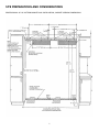
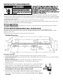
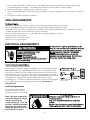
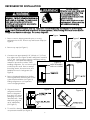
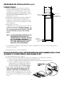
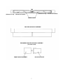
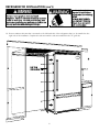
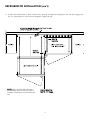
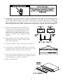
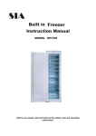
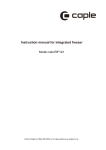
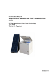
INSTALLATION
INSTRUCTIONS
VIKING RANGE CORPORATION
111 Front Street
Greenwood, Mississippi (MS) 38930 USA
(662) 455-1200
BUILT-IN BOTTOM MOUNT REFRIGERATOR/FREEZER
BRTGK72SS-GRILLE KIT
(FOR PROFESSIONAL SERIES ONLY)
IMPORTANT - PLEASE READ AND FOLLOW
Make sure that incoming voltage is the same as unit rating. An electric rating plate specifying voltage, frequency, wattage,
amperage, and phase is attached to the product.
Please refer to Installation Instructions provided with bottom mount refrigerator/freezer for additional information.
To reduce the risk of fire, electric shock, or injury to persons, installation work and electrical wiring must be done by qualified
people in accordance with all applicable codes and standards, including fire-rated construction.
The installer should leave these instructions with the consumer who should retain for local inspector’s use and for future
reference.
GENERAL INFORMATION
Your safety and the safety of others
is very important.
We have provided many important safety
messages in this manual and on your
appliance. Always read and obey all
safety messages.
This is the safety alert symbol. This
symbol alerts you to hazards that
can kill or hurt you and others.
All safety messages will be
preceded by the safety alert symbol and
the word “DANGER” or “WARNING”.
These words mean:
You will be killed or seriously injured if you
don’t follow instructions.
TIP OVER HAZARD
Refrigerator is top heavy and tips easily
when not completely installed.
Keep doors closed until refrigerator is
completely installed and secured with
lag bolts to rear wall.
Use two or more people to move and
install refrigerator.
Failure to do so can result in death or
serious injury
Most of the refrigerator’s
weight is at the top. Extra care
is needed when moving the
refrigerator to prevent tipping.
Keep cardboard shipping
piece or plywood under
refrigerator until it is installed in
the operating position.
It is your responsibility to :
-comply with installation specifications and dimensions
-properly install refrigerator
You can be killed or seriously injured if
-remove any moldings or decorative panels that prevent the refrigerator from
you don’t follow instructions.
being serviced
-make sure that you have these materials, (not provided with the unit), which
All safety messages will identify the
are necessary for proper installation:
hazard, tell you how to reduce the chance
2 - 1/4” (6 mm) copper tubing with shutoff valve
if injury, and tell you what can happen if
2 - 1/4” (6mm) compression fitting
the instructions are not followed.
6 - #8 x 3” (7.6 cm) wood screws (Longer screws may be required.)
2 - saddle valves (do not use self-piercing valves).
-assure that floor will support refrigerator, door panels and contents,
(approximately 1200 lbs. [540 kg.])
-provide a properly grounded electrical outlet
-assure that location will permit appliance doors to open 90o minimum
SITE PREPARATIONS AND CONSIDERATIONS
PROFESSIONAL 36” W. BOTTOM MOUNT DUAL INSTALLATION, CABINET OPENING DIMENSIONS
83 1/4” (211.5 cm) Min.
84 1/16” (213.5 cm) Max.
2
WATER SUPPLY REQUIREMENTS
ELECTRICAL SHOCK HAZARD
Some water may remain in line. Electric
drill must be grounded to prevent severe or
lethal shock if water is in line and enters drill
during use.
Use only 1/4” (6 mm) copper tubing for water line. Do
Not install copper tubing in area where temperatures
drop below 35oF (1.7oC). Before attaching copper tubing
to refrigerator, flush at least 2 quarts (1.9 L) of water
through the copper tubing and into a bucket to get rid of
any particles in the water line.
•Connect 1/4” (6mm) flexible copper tubing to household plumbing in compliance with local codes and ordinances.
•Length of copper tubing must reach from water supply connection to refrigerator connection plus an additional length
to facilitate moving the refrigerator out of enclosure for cleaning or service. Tubing should be soft instead of rigid and
ends should be free of burrs.
•Copper tubing route must be above 35oF (1.6oC) to prevent water line from freezing.
•If saddle valve is not used, place a separate shut-off valve in an easily accessible location between water supply and
refrigerator. Do not locate shut-off valve behind refrigerators.
•Do not use plastic water lines.
Do not use self-piercing valve. Viking Range Corporation is not responsible for property damage due to improper
•D
installation or water connection.
Do not use with reverse osmosis water filtration system. This will void warranty
•D
•Connect a vertical or horizontal 1/2” (1.2 cm) to 1 1/4” (3.2 cm) COLD water line near refrigerator area.
•Run water line through the floor, back or side wall. Tubing should lay flat on floor underneath refrigerator. Clamp
tubing to wall or floor.
•Water pressure must be greater than 20 psi and less than 120 psi.
Plumbing Dimensions
To rough in water line:
1. Turn OFF main water supply. Turn ON nearest faucet long enough to clear line of water.
2. Vertical cold water line: Use grounded electric drill or hand drill to drill 3/16” (4.5 mm) hole in an easily accessible
location in water line.
Horizontal cold water line: Use grounded electric drill or hand drill to drill 3/16”
(4.5 mm) hole in the TOP of the water line. This will keep sediment from
collecting in valve.
3. Position washer over hole in water line. Place both halves of saddle valve bracket
against water line. turn saddle valve handle clockwise until firmly seated. The
saddle valve is now in the closed position. Tighten packing nut. Evenly and
firmly tighten bracket screws so washer will make a water-tight connection. Do
not overtighten screws: copper tubing could be crushed.
4. Check that both ends of copper tubing are cut square. Slide compression nut
and sleeve onto copper tubing. Insert end of copper tubing completely into
valve outlet. Tighten compression nut to outlet with adjustable wrench. Do not
overtighten.
3
5. Turn on main water supply. Check for leaks. Turn saddle valve handle counterclockwise and run water through
copper tubing and into a bucket. Turn saddle valve clockwise to shut off water to copper tubing.
6. Route copper tubing to refrigerator area or water filter area.
7. Leave an additional length of copper tubing coil to facilitate moving the refrigerator out of enclosure for cleaning or
service.
8. See page11 for water connection instructions.
AREA REQUIREMENTS
Verify the following:
•Refrigerators can fit into residence and can be moved around corners and through doorways.
•Floors can support refrigerator’s weight plus food weight (approximately 1200 pounds each).
•Rear wall is solid and is able to support a (2) horizontally mounted 2X4s (included) bolted to 2 wall studs. The 2X4
board bolt heads must be flush with 2X4 to prevent obstruction.
•Remove anything attached to rear or side walls that can obstruct refrigerator opening.
•Cutout dimensions are accurate.
•Electrical outlet is in correct location.
•Water line in in correct location.
ELECTRICAL REQUIREMENTS
ELECTRICAL SHOCK HAZARD
Plug into a grounded 3-prong outlet.
DO NOTremove ground plug.
DO NOT use an adapter.
DO NOT use an extension cord.
Failure to follow these instructions could result in
fire or electrical shock.
If codes permit a separate grounding wire to be
used, it is recommended that a qualified electrician
determine that the grounding path is adequate.
Do Not ground to a gas pipe. Check with a
qualified electrician if you are not sure the
appliance is properly grounded. Do Not have a
fuse in the neutral or grounding circuit.
It is the customer’s responsibility to:
•contact a qualified electrical installer.
•assure that the electrical installation is adequate and in conformance with the
National Electrical Code, ANSI/NFPA 70-latest edition or Canadian Electrical
Code C22.1-1998 and C22.2 No. 0-M91 (or latest edition), and all local codes
and ordinances. 120 volt, 60-Hz, 15 amp, fused, electrical supply is required. It
is recommended that a separate circuit serving only this appliance be provided.
This appliance is equipped with a power supply cord having a 3-prong
grounding plug. To minimize possible shock hazard, the cord must be plugged
into a mating 3-prong, grounding-type wall receptacle. Do not use an
extension cord.
Anti-Tip Requirements
The anti-tip boards should be
fastened into position prior to
moving the unit into the opening.
TIP OVER HAZARD
Refrigerator is top heavy and tips easily when not
completely installed.
Keep doors closed until refrigerator is completely
installed.
Use two or more people to move and install refrigerator.
Failure to do so can result in death or serious injury
Note: The space between the
rear of the refrigerator cabinet
and the condensing unit
assembly housing is 1 1/2” (3.8
cm) deep. Additional mounting
boards may be required if the
refrigerator does not touch the
back wall of the enclosure
4
REFRIGERATOR INSTALLATION
TIP OVER HAZARD
Refrigerator is top heavy and tips easily
when not completely installed. Keep
doors closed until refrigerator is
completely installed and secured with
lag bolts to rear wall.
Use two or more people to move and
install refrigerator. Failure to do so can
result in death or serious injury.
Use two or more people to move and install
refrigerator. Failure to follow this instruction can
result in back or other injury. To avoid personal
injury, wear gloves when performing any
installation procedure and wear eye protection
when cutting metal straps.
Most of the refrigerator’s weight is at the top. Extra care is needed when moving the refrigerator to prevent tipping.
Do Not remove protective film until refrigerator is in operating position. All four leveling rollers must contact the floor
to support and stabilize the full weight. Do not drop refrigerator.
Figure 1
1. Remove exterior shipping materials prior to moving
refrigerator into home. Remove top and bottom strap (see
Figure 1).
Figure 2
2. Remove top cap (see Figure 1).
3. Cut carton rear approximately 1/4” (.64 cm) to 1” (2.5 cm)
from right corner (see Figure 2) with a utility knife extended
1/4” (.6 cm). Remove carton, exterior packaging, and lag
screw tape. Save cardboard shipping
material to protect floor surface when
installing refrigerator. Do not remove nylon
cord from power cord. Remove anti-tip
board, lag screws, door trim insert, and
kickplate from rear of refrigerator (see
Figure 3).
BACK VIEW
Figure 3
Figure 4
ANTI-TIP BOARDS
AND LAG SCREWS
KICKPLATE
4. Remove shipping brackets from skid by
removing 4 bolts (2 each side) with a 7/16”
socket head screwdriver (see Figure 4).
•Tilting refrigerator is not required to
remove shipping brackets.
5. Slip cart between
refrigerator and skid.
Remove refrigerator
from skid. Use excess
packaging to protect
decorative trim. Verify
that leveling legs are
up (0” adjustment)
(see Figure 5).
Figure 5
SKID
6. To avoid floor damage,
use protective material (see Figure 6).
5
Figure 6
REFRIGERATOR INSTALLATION (con’t)
Securing the refrigerators
1. Locate and predrill 1/4” (.6 cm) holes in the first
mounting board (supplied). Countersink the bolt
heads into the 2 x 4 board using a 1-1/8” (2.9 cm)
counterbore wood bit 1-1/4” (.6 cm) deep. Locate
and mark 2 wall studs to mount the first 2 x 4 board.
ACCESS TO
Do not cover the electrical outlet (see “Site
LAG BOLTS
Preparations” on p. 3).
2. Bolt anti-tip mounting board securely to wall studs.
3. Predrill 1/4” (.6 cm) in second mounting board
(supplied). Countersink the bolt heads into the 2x4
board using a 1-1/8” (2.9 cm) counterbore wood bit OTE:
EFRIGERATOR IN A 24"
1/4” (.6 cm) deep.
EEP OPENING WILL BE
4. Attach flush to first 2x4.
LUSH AT FRONT SURFACE.
If application does not have studs, mount to the wall SE 1-1/2" THICK MOUNTING
OARD. IF REFRIGERATOR
using a minimum of four 1/4” (.6 cm) diameter
TO PROTRUDE BEYOND
fasteners (not supplied). If cabinets are deeper than4", ADDITIONAL MOUNTING
24”, mounting board must be shimmed. The shim OARD THICKNESS IS
EQUIRED.
must be structurally secured to the mounting
board.
NOTE: THE SPACE BETWEEN THE REAR OF THE
REFRIGERATOR CABINET AND THE
CONDENSING UNIT ASSEMBLY HOUSING
IS 3” (7.6 CM) DEEP. ADDITIONAL
MOUNTING BOARDS MAY BE REQUIRED
IF THE UNIT DOES NOT TOUCH THE
BACK WALL OF THE ENCLOSURE.
24"
3”
1-1/2"
WALL BOARD
OR PLASTER
2x4 MOUNTING
BOARDS
BOARD
WALL STUD
LAG BOLT WITH
EXTENDED SHAFT
LEVELING
WHEEL BOLTS
LEVELING
FEET
5. To avoid water line damage, verify water line is secure so refrigerator does not run over the water line when
moved into opening.
6. Repeat steps above for second refrigerator.
Before moving the refrigerators in place, confirm the finished dimensions, electrical, and plumbing locations, minimum
door clearances, and door panel installations are accurate (see pages 2, 3, & 4).
7. Position refrigerators in front of cutout.
8. Remove the top air grille assemblies from both of the refrigerators. (See illustrations on page 7)
a. Remove the center grille blades by lifting up and pulling forward.
b. Remove the grille/end cap assembly by removing the four (4) screws in each black air duct.
c. Remove the black air ducts by removing the
eight (8) screws on the right hinge model and
the seven (7) screws on the left hinge model.
Save the air ducts for the 72” grille installation.
9. Verify operation by plugging power cord. Power
switch will be shipped in the ON position and
showroom switch will be in the ON position. (If
showroom switch is switched to the “OFF” position,
showroom mode is engaged and power is shut off to
the compressor. This mode is for showroom display
only.)
6
TOP
(4 Screws on top - 4 Screws on bottom)
(4 Screws on top - 3 Screws on bottom)
SCREW HOLES
TOP VIEW OF GRILLE ASSEMBLY
EXPLODED SIDE VIEW OF GRILLE ASSEMBLY
(15 Screws Used)
FRONT GRILLE ASSEMBLY
BLACK AIR DUCTS
7
REFRIGERATOR INSTALLATION (con’t)
TIP OVER HAZARD
Refrigerator is top heavy and
tips easily when not completely
installed.
Use two or more people to
move and install refrigerator.
Failure to do so can result in
death or serious injury
Use two or more people to move and install
refrigerator. Failure to follow this instruction can result
in back or other injury. To avoid personal injury, wear
gloves when performing any installation procedure and
wear eye protection when cutting metal straps.
10. Remove cabinet side trim that is mounted on the left hand side of the refrigerator that is to be installed on the
right side of the installation. Replace this side trim with the side trim included in the 72” grille kit.
Left Hand
Cabinet Side Trim
8
REFRIGERATOR INSTALLATION (con’t)
11. Position the left hand unit so when rolled into the opening, the right hand refrigerator’s left side trim engages into
the “U” shaped portion of the left side refrigerator’s right side trim.
Anti-Tip
Lag Bolts
Cabinet
Side Trim
NOTE: When leveling each refirgerator
and installing water connections, refer to
installation instructions provided with each
unit.
Cabinet Side Trim
(NOTE: “U” Shape)
9
Electrical Shock Hazard
Disconnect power or turn power disconnect switch to
OFF position before performing any installation
procedure. Failure to do so can result in death or
electrical shock
12. Roll refrigerators into cutout to within 3” (7.6 cm) of being flush with kitchen cabinets. To avoid kitchen cabinet
damage, place cardboard between kitchen cabinets and refrigerator. Push cardboard back with refrigerator and
remove cardboard when refrigerators are in place. Remove power cord slack by pulling nylon cord straight out
while pushing refrigerator completely into place. Power and nylon cords will rest along refrigerator side. Note:
When moving the unit into position, be careful not to crimp, kink, or crush the copper water supply line.
13. Adjust to desired height and level refrigerator by
turning front and rear leveling wheel bolts clockwise
to raise refrigerator and counterclockwise to lower
refrigerators. Level refrigerators so that the door
tops are in the same planes and that the door gap
between the two units is even (refrigerator sides are
parallel).
14. Align refrigerators with sides of kitchen cabinets by
adjusting leveling wheels. Rotate leveling feet until
firmly in place against floor.
15. Assemble and install 72” grille. See page 11 for instructions.
16. Secure lag bolts. Screw lag bolts securely into 2 x 4 mounting
board(s) using an 8” (20.3 cm) long 7/16” socket. Refer to “Site
Preparation” section on page 2 for more information.
17. Open doors. Displays should flash. Press any key. There is a 6
minute delay before the refrigerator starts. Verify the position of
each switch if there is no power to refrigerators
18. Replace center grill blade.
10
72” GRILLE ASSEMBLY
GRILLE ASSEMBLY
BLACK AIR DUCTS
REAR VIEW OF
GRILLE ASSEMBLY
TOP
SCREW HOLES
(16 Holes - 15 Screws)
To assemble/install 72” grille:
1.
2.
3.
4.
Assemble air ducts to 72” grille using the supplied 15 screws.
Remove 72” center grille blade by lifting up and pulling forward.
Insert air ducts and 72” grille into refrigerators. Screw air ducts into units with four screws per unit.
Return to step 16 on page 10 to secure refrigerators.
11
WATER CONNECTION
•Refer to water supply requirement section for preliminary installation and site preparation (see page 3).
•Do not use plastic water lines between refrigerator and supply . Plastic water lines can fail due to fatigue over
time and cause extensive damage to product and the home.
•Use only 1/4” (.6 cm) copper tubing for water line.
•Do not connect to reverse osmosis water filtration system.
The garden hose fitting, compression nut, and sleeve are located in the literature packet.
1. Pull copper line from plumbing forward from underneath refrigerator (see Figure A). Flush air and impurities from
water line by turning on water supply and running two (2) quarts of water into a bucket. Remove plastic cap from
water valve fitting.
2. Loosely connect garden hose fitting to water valve inlet port (see Figure B).
3. Slide copper tubing through brass ferrule, and brass sleeve (see Figure C).
4. Connect brass nut on copper tubing to garden hose fitting (see Figure D).
5. Tighten garden hose fitting.
6. Turn on water supply to refrigerator and check for leaks.
7. Turn off water supply to refrigerator and correct any leaks. Repeat this process until no leaks exist.
8. Completely turn on water supply to refrigerator.
9. Verify drain pan is installed and aligned. Drain pan must be pushed past and over initial stopping point.
SOLENOID
VALVE
Figure A
GARDEN HOSE TYPE
FITTING
Figure B
Figure C
CONNECT TUBE TO GARDEN
HOSE TYPE FITTING
Figure D
12
KICKPLATE INSTALLATION
The kickplate consists of a (2) part assembly: one top vented panel and one bottom solid panel. Install kickplate with
air vents to the top. Kitchen flooring must allow kickplate to be removed. See “Site Preparations” for height clearance
(page 2).
To Install:
1. Insert the bottom (solid panel) into the open end of the top (vented) panel. The holes in the bottom panel (Item C)
should line up with the slots (Item A) in the top panel.
2. Position the kickplate assembly along the front edge of the refrigerator.
3. Attach the clip (Item B) to the top of the top panel to hold drain pan in place. This clip is designed to hold the
drain pan in place after the kickplate is installed.
4. Align the holes (Item D) on both ends of the top (vented) panel with the holes in the base of the refrigerator.
5. Attach the kickplate to the refrigerator on each side with the two chrome screws.
6. Adjust the bottom (solid) panel to the desired height and fasten in place by placing the black screws through the
slots (Item A) on each end of the top panel and into the hole (Item C) on the bottom panel and fasten securely.
Top vented
panel
Item B
Item D
Item A
Item C
Bottom solid
panel
Figure 1
Chrome
screws
Figure 2
13
Black
screws
AIR DISCHARGE SIDE VIEW
DOOR STOP ADJUSTMENT
1. Remove center grill louver from the top air grill assembly.
2. Remove top air grill by removing (4) 1/4” screws with an 8”
(20.3 cm) long magnetic 1/4” (.6 cm) nut driver. Pull
assembly forward.
3. Open refrigerator door so door stop arm and shoulder
screw are accessible. Shoulder screws should be in 110o
door opening position.
4. Remove shoulder screw and place shoulder screw in the
90o or 120o door opening position.
5. Replace to air grille assembly.
HINGE ADJUSTMENT
Verify proper door alignment. Only the top hinge is adjustable.
1. Remove the center grill louver from the top air grille
assembly.
2. Remove top air grill by removing (4) 1/4” screws with an 8”
(20.3 cm) long magnetic 1/4” (.6 cm) nut driver. Pull
assembly forward.
3. Loosen the (4) top hinge screws.
4. Align refrigerator door by lifting.
5. Tighten screws.
6. Replace top air grille assembly.
14
BASIC SPECIFICATIONS AND DIMENSIONS
DESCRIPTION
VCBB363 - DUAL INSTALLATION
Overall Width
72” (182.8 cm)
Overall Height from Bottom
Min. 83 1/4” (211.5 cm) to Max. 84 1/16” (213.5 cm)
Overall Depth from Rear
To rear edge of side trim
To front of top grille
To end of handle bracket
Cutout Width
71 1/2” (181.6 cm)
Cutout Height
83 1/4” (211.5 cm) min.; 84 1/16” (213.5 cm) max.
Cutout Depth
24” (61.0 cm) min.
Electrical Requirements
(2) - 115 volt, 60 Hz, 15 amp dedicated circuit; 3-wire cord with
grounded 3-prong plug attached to product.
Maximum Amp Usage
22 3/16” (56.4 cm)
24 11/16” (62.7 cm)
27 1/4” (69.2 cm)
9.9 amps (per unit)
Inlet Water Requirements
(2) - 1/4” copper tubing inlet waterline; minimum 20 psi;
maximum 120 psi
Overall Interior Dimensions
•Refrigerator
•Freezer
•Total Capacity
(per unit)
15.2 cu. ft. (.43 cu. meters)
5.1 cu. ft. (.14 cu. meters)
20.3 cu. ft. (.57 cu. meters)
Approximate Shipping Weight
575 lbs. (258.8 kg) - per unit
15
Viking Range Corporation
111 Front Street • Greenwood, Mississippi (MS) 38930 USA • (662) 455-1200
Specifications subject to change without notice
For more product information, call 1-888-VIKING1 (845-4641), or visit our web site at http://www.vikingrange.com
F20083A
(PS0202VR)