1
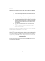
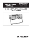
Instruction Manual Manual de usuario Model 1672 Triple Output Power Supply Contents Section Description Page No. CONTENTS 1 1 TEST INSTRUMENT SAFETY 2 2 INTRODUCTION 3 2.1 INTRODUCTION 2.2 FEATURES 3 3 Installation 4 3.1 INTRODUCTION 3.2 UNPACKING 3.3 INPUT POWER REQUIREMENTS 3.4 SYSTEM CONFIGURATION 3.5 INSTALLATION 3.6 OPERATING INSTRUCTIONS 4 4 4 5 5 5 3 4 5 6 Setting the Output Voltage and Current 6 Tracking Mode Operation 7 Connecting Multiple Units and Fixed Output 8 7 TECHNICAL SPECIFICATIONS 9 8 CONTROLLS AND INDOCATORS 10 8.1 INTRODUCTION 8.2 UNPACKING 8.3 INPUT POWER REQUIREMENTS 8.4 PANEL LAYOUT 10 10 11 12 MAINTENANCE 13 9.1 INTRODUCTION 9.2 PREVENTIVE MAINTENANCE 9.3 SERVICE INFORMATION 9.4 TEST EQUIPMENT REQUIRMENTS 13 13 14 15 10 CUSTOMER SUPPORT 16 11 12 WARRANTY INFORMATION SERVICE INFORMATION 17 18 19-36 9 Manual de usuario 1 Section 1 - Test Instrument Safety WARNING - Normal use of test equipment exposes you to a certain amount of danger from electrical shock because testing must sometimes be performed where exposed voltage is present. An electrical shock causing 10 milliamps of current to pass through the heart will stop most human heartbeats. A Voltage as low as 35 volts dc or ac (rms.) should be considered dangerous and hazardous since it can produce a lethal current under certain conditions. Higher voltages pose an even greater threat because such voltage can more easily produce a lethal current. Your normal work habits should include all accepted practices to prevent contact with exposed high voltage and to steer current away from your heart in case of accidental contact with high voltage. You will significantly reduce the risk factor if you know and observe the following safety precaution. 1. Don’t expose high voltage needlessly. Remove housings and covers only when necessary. Turn off equipment while making test connections in high voltage circuits. Discharge high voltage capacitors after removing power. 2. If possible, familiarize yourself with the equipment being tested and the location of its high voltage points. However, remember that high voltage may appear at unexpected points in defective equipment. 3. Use an insulated floor material or a large, insulated floor to stand on and an insulated work surface on which to place equipment and make certain such surfaces are not damp or wet. 4. Use the time proven “one hand in the pocket” technique while handling an instrument probe. Be particularly careful to avoid contacting a nearby metal object that could provide a good ground return path. 5. When testing ac powered equipment, remember that ac line voltage is usually present on some power input circuits such as the on-off switch, fuses, power transformer etc. any time the equipment is connected to an ac outlet, even if the equipment is turned off. 6. Some equipment with a two-wire ac power cord, including some with polarized power plugs, is the “hot chassis” type. This includes most recent television receivers and audio equipment. A plastic wooden cabinet insulates the chassis to protect the customer. When the cabinet is removed for servicing, a serious shock hazard exists if the chassis is touched. Not only does this present a dangerous shock hazard, but damage to test equipment. Always connect an isolation transformer between the ac outlet and the equipment under test. The B&K Precision Model TR-110 or 1604A Isolation Transformer or Model 1653A or 1655A AC Power Supply is suitable for most applications. To be on the safe side, treat all two-wire ac equipment as “hot chassis” unless you are sure it is isolated chassis or an earth ground chassis. 7. On test instruments or any equipment with a 3-wire ac power plug, use only a 3-wire outlet. This is a safety feature to keep the housing or other exposed elements at earth ground. 8. B&K Precision products are not authorized for use in any application involving direct contact between our product and the human body or for use as a critical component in a life support device or system. Here “direct contact” refers to any connection from or to our equipment via any cabling or switching means. A “critical component” is any component of a life support device or system whose failure to perform can be reasonably expected to cause failure of that device or system or to affect its safety or effectiveness. Never work all alone. Someone should be nearby to render aid if necessary. Training in CPR (cardio-pulmonary resuscitation) first aid is highly recommended. 2 Section 2 Introduction 2.1 INTRODUCTION 2.2 FEATURES 2.1 INTRODUCTION The Model 1672 is a Triple Output Regulated DC Power Supply that provides one fixed output (5V/ 3A) and two variable outputs (0 – 32V/ 0 – 3A) ratings. The variable outputs can work independently, or in series tracking, or parallel mode. 2.2 FEATURES § Independent control of Voltage and Current controls for variable output. § CV/CC operation. § Separate 3 digit displays for voltage (Green) and current (Red) for both variable outputs. § LED indication for CV (Green)/ CC (Red) mode. § Overload indication LED for Fixed output. § Series tracking and parallel mode operation. § Power On/Off switch on front panel. § Input voltage selection on rear side (115 Vac/ 230Vac). 3 Section 3 Installation 3.1 3.1 INTRODUCTION 3.2 UNPACKING 3.3 INPUT POWER REQUIREMENTS 3.4 SYSTEM CONFIGURATION 3.5 INSTALLATION 3.6 OPERATING INSTRUCTIONS INTRODUCTION This unit is tested prior to shipment. It is therefore ready for immediate use upon receipt. The initial physical inspections should be made to ensure that no damage has been sustained during shipment. 3.2 UNPACKING Inspect the packing box on receipt for any external damage. If any external damage is evident, remove the instrument and visually inspect it’s case and parts for any damage. If damage to the instrument is evident, a description of the damage should be noted on the carrier’s receipt and signed by the driver or carrier agent. Save all shipping packaging for inspection. Forward a report of any damage to the agent through which the unit is procured. Retain the original packing in case subsequent repackaging for return is required. Use of the original packing is essential. 3.3 INPUT POWER REQUIREMENTS The instrument can operate on 115V or 230V 50 or 60Hz Line selector plug on the rear panel allows you to select the line voltage. Before connecting the power plug to an AC line outlet, be sure to check that voltage Selector plug is set in the correct position corresponding to the line voltage in your location and the fuse rating is as shown in the table. 4 3.4 SYSTEM CONFIGURATION The Model 1672 works in independent mode, series tracking mode or parallel mode. User can select the desired mode by following the user instructions. 3.5 3.5.1 INSTALLATION AC Input Power Connection Before connecting line ensure the following: a) That correct line voltage tap is selected as described above. b) That the input fuse rating is as specified. SELECTOR 115V 230V 3.5.2 LINE VOLTAGE 100 ~ 125V 50/60 Hz 3.0A 220 ~ 240V 50/60 Hz 1.5A FUSE 6A 3A Load Connections Connect the appropriate load between +ve (Red) and –ve (black) terminal. For model 1672 the load connection is same as above while using independent output. In serial tracking mode of operation, connect the appropriate load between +ve (Red) terminal of master and –ve (black) terminal of slave. In parallel mode of operation, connect the appropriate load between +ve (Red) terminal and –ve (black) terminal of slave OR between +ve (Red) terminal of master and –ve (black) terminal of slave. 3.6 OPERATING INSTRUCTIONS Before applying power to unit, make sure that input voltage setting is correct and the ventilation holes are not blocked. Ensure that Ventilation Fan (26) is working well (it should turn on at power on condition). Do not load the output if FAN is not working otherwise it may cause the overheating. 5 Section 4 SETTING THE OUTPUT VOLTAGE AND OUTPUT CURRENT 1. 2. 3. 4 5. 6. 7. As per load requirement calculate the voltage and maximum current limit to be set on Output. Note: V=IxR Disconnect the load from output terminals. For current limit adjustment, turn the current adjustment knob (11) counter-clockwise to get minimum current output. Short the circuit between the ⊕ (7) and θ (5) output terminals by the accessory leads. Vary the current adjustment knob clockwise until the 1672 current (Red) displays the required current limit. The C.C. LED will be lighted while adjusting the current limit. Remove the accessory lead after current limit adjustment. The voltage will be displayed again and C.V. LED (Green) will be lighted. Vary the voltage adjustment knob (10) to get the desired output voltage on the (Green) display. Depending on Load condition power supply will work either in C.V. or in C.C. mode. The automatic changeover is indicated by the C.V. / C.C. LED’s. Model 1672 has two variable outputs, which can work independently or in series tracking or parallel mode with pull and push switch arrangements provided with master voltage and current control knobs. Independent Mode Ensure the master voltage and current control knobs are in PUSH condition to operate the variable outputs independently. 6 Section 5 Serial Tracking Mode In this mode negative output terminal of the Master gets connected internally to positive output terminal of the Slave . The output is available across Positive output terminal of the Master and Negative output terminal of the Slave . 1. PULL the Voltage adjustment knob of Master (10). The green LED (14) will light up to indicate serial tracking mode. 2. Turn the Current adjustment knob of Slave (19) clockwise to maxi mum. Set output voltage with the Voltage adjustment knob of Master. The display of Master shows half voltage of the actual output available across Positive output terminal of the Master and Negative output terminal of the Slave . Parallel tracking Mode In this mode Positive output terminal of Master gets connected internally to Positive output terminal of Slave and Negative output terminal of Master gets connected to Negative output terminal of Slave. The output voltage will be same as the Master set value and current and the output current is twice the set master output current. 1. PULL the Current adjustment knob of Master (11). The red LED (15) and the red (23) CC LED of the slave output will light up to indicate parallel tracking mode. 2. Turn both of the voltage adjustment knob (18) and current adjustment knob (19) of the slave output clockwise to maximum. 3. Set output voltage with the Voltage adjustment knob of Master. The output current shall be twice of the set master output current. Multiple units in serial mode For achieving the higher voltage, two or more units can be connected in series (Max 240V). The output voltage will be the SUM of twice of set voltage of the Master. 1. 2. 3. Set all the 1672, which would be connected in serial operation under serial tracking mode as described in serial tracking mode and adjusts to the same output. Connect the Negative of Slave output terminal of the unit 1 to the Positive of Master output terminal of the unit 2. The output shall be available across Positive of Master terminal of unit 1 and Negative of Slave terminal of unit 2. 7 Section 6 Multiple units in parallel mode The power supply 1672 can be connected two or more units in parallel to obtain a higher current output (Max. 24A only). 1. Set all the 1672 which will be connected in parallel operation under parallel tracking mode as described in parallel tracking mode and adjust all units to the same output voltage. 2. Make the parallel connection of Positive and Negative terminals of Master and Slave outputs of all units. The output voltage of the system will be the same for all the units. The output current of the system will be the sum of each unit. FIXED 5V/3A OUTPUT This is the standard 5V/ 3A power output provided for supplying the power to TTL logic circuits. When the load exceeds 3A. The red OVER LOAD LED (4) will light up. The output voltage will lower and the power supply will be under C.C. Mode. 8 Section 7 Technical Specifications Output Parameters Number of Outputs Three ( One fixed and Two variable) Range 0 to 32 Vdc/ 0 to 3A ( variable) and 5V/ 3A (fixed) Max. output power 195VA Constant Voltage Mode Line regulation <0.01% + 5mV Load regulation <0.2% + 10mV Ripple & Noise <1mVrms Temp. coefficient <300PPM/ ° C Constant Current Mode Line regulation <0.2% + 5mA Load regulation <0.2% + 8mA Ripple & Noise <1mArms Tracking Operation Slave tracking error < 0.5%+3 digital of the master Series Single Supply Reg. 5V Fixed Output Line Regulation not specified Load Regulation not specified Ripple & Noise <1mVrms Voltage Accuracy 5V ± 0.85V Display Voltage 3 digits 0.56” Green LED Current 3 digits 0.56” Red LED Accuracy <0.1% + 3 digits Input Parameters Input voltage range 115/230 ± 10% Input frequency 50/ 60Hz Operating Environment Temperature 50 ° F to 104 ° F (10 ° C to 40 ° C) Humidity 90 % R.H. All specifications apply to the unit after a temperature stabilization time of 15 minutes Mechanical Specifications Dimensions Weight 9x6.7x12.2lbs. (230X170X310mm) (WXHXD) 12.6lbs. (5.7kg) 9 Section 8 CONTROLS AND INDICATORS 8.1 8.1 INTRODUCTION 8.2 FRONT PANEL DESCRIPTION 8.3 REAR PANEL DESCRIPTION 8.4 PANEL LAYOUT INTRODUCTION This chapter explains the operating procedure of the unit. The operation is made very simple by providing front panel Potentiometer control. The Front and rear panel description of the instrument is provided first. Then the operating procedure is explained in detail. 8.2 FRONT PANEL DESCRIPTION Refer to the Front panel drawings and the numbers assigned to various objects on the front panel. (see page 12) 1. 2. 3. 4. 5. 6. 7. 8. 9. 10. 11. 12. 13. 14. 15. POWER SWITCH: Pushing the switch “ON” will light the LED display to indicate power “ON”. Negative output terminal of the Fixed 5V/3A output (black). Positive output terminal of the Fixed 5V/3A output (red). Over load indicator LED (Red) for Fixed 5V/3A output. Negative output terminal of the Master 0-32V/0-3A Output (black). Ground terminal of the Master output (green). Positive output terminal of the Master 0-32V/0-3A Output (Red). C.C. Mode LED (Red) for the Master to indicate constant current. C.V. Mode LED (Green) for the Master to indicate constant voltage. Master voltage adjustment knob with pull and push switch mechanism for series tracking mode operation and parallel mode operation along with pull switch of current adjustment knob. Master current adjustment knob with pull and push switch mechanism for parallel mode operation. Master Voltage Indicator Display in full 3-digits Green 0.56” LED. Master Current Indicator Display in full 3-digits Red 0.56” LED. Series Mode Indicator LED (Green). Parallel Mode Indicator LED (Red). 10 16. Slave Voltage Indicator Display in full 3-digits Green 0.56” LED. 17. Slave Current Indicator Display in full 3-digits Red 0.56” LED. 18. Voltage Adjustment knob for adjusting Slave output voltage when master power is at C.V. Mode. 19. Current Adjustment knob for adjusting Slave output current when master power is at C.C. Mode. 20. Negative output terminal of the Slave 0-32V/0-3A Output (black). 21. Ground terminal of the Slave output (green). 22. Positive output terminal of the Slave 0-32V/0-3A Output (Red). 23. C.C. Mode LED (Red) for the Slave to indicate constant current. 24. C.V. Mode LED (Green) for the Master to indicate constant voltage. 8.3 REAR PANEL DESCRIPTION Refer to the Rear panel drawings and the numbers assigned to various objects on the front panel. (see page 12) 25. Heat sink for dissipating the heat of power devices. 26. Fan Ventilation (80mm 12V DC Fan). 27. Power input socket 28. Fuse holder and input line selector. 29. The input Line voltage indicator. (Refer to ∇ mark) 11 8.4 PANEL LAYOUT FRONT PANEL OF 1672 REAR PANEL OF 1672 12 Section 9 Maintenance 9.1 9.1 INTRODUCTION 9.2 PREVENTIVE MAINTENANCE 9.3 SERVICE INFORMATION 9.4 TEST EQUIPMENT REQUIREMENTS INTRODUCTION This chapter gives information about preventive maintenance and service information of the unit. 9.2 PREVENTIVE MAINTENANCE Please follow the following preventive steps to ensure the proper operation of your instrument. l l l l Never place heavy objects on the instrument. Never place a hot soldering iron on or near the instrument. Never insert wires, pins or other metal object into ventilation fan. Never move or pull the instrument with power cord or output lead. Especially never move instrument when power cord or output lead is connected. l Do not obstruct the ventilation holes in the rear panel. As this will increase the internal temperature. l Do not operate the instrument with the cover removed unless you are a qualified service technician. l Clean and recalibrate the instrument on a regular basis to keep the instrument looking nice and working well. Remove any dirt, dust and grime whenever they become noticeable on the Outside cover with a soft cloth moistened with a mild cleaning solution. 13 9.3 SERVICE INFORMATION WHEN THE UNIT IS NOT TURNING ON. Check if the power ON/OFF switch is turned ON. If not, then check the power cord. Please make sure that the power cord is properly connected to the unit. Please also check the main switch. And ensure that the AC supply at your site is the same as the one mentioned at the rear chassis of the unit. FUSE REPLACEMENT If the fuse blows, the LED will not light and the instrument will not operate. Replace only with the correct value fuse. The fuse is located on the rear panel adjacent to the power cord receptacle. Remove the fuse holder assembly as follows: Unplug the power cord from rear of the instrument. Insert a small screwdriver in fuse holder slot (located between fuse holder and receptacle). When reinstalling fuse holder, be sure that the fuse is installed so that the correct line voltage is selected. 1. 2. 14 9.4 TEST EQUIPMENT REQUIREMENTS (only required when doing a performance verification test) The following instruments will be required to test the complete installation of the unit. 1). A 4½ Digit Multimeter for verifying the output voltage and current. 2). A 20 MHz dual channel oscilloscope for verifying the Ripple in the DC Output/s. 3). A Resistive load to suit the maximum output current from the unit depending on the model and capacity. 4). A Standard calibrated current shunt to measure the output current. 15 Section 10 Customer Support B&K Precision offers courteous, professional technical support before and after the sale of their test instruments. The following services are typical of those available from our toll-free telephone number. 1-800-462-9832 l Technical advice on the use of your instrument. l Technical advice on special applications of your instrument. l Technical advice on selecting the test instrument for a given task. l Information on optional accessories for your instrument. l Information on instrument repair and re-calibration services. l Replacement parts ordering. l Availability on service publications. l Information on other B&K Precision instruments. l Information on other B&K Precision Catalog. The name of your nearest B&K Precision Distributor. Call toll free 800-462-9832 Monday through Thursday 8:00 A.M. to 5:00 P.M. Friday 8:00 A.M. to 12:00 P.M. Pacific Standard Time (Pacific Daylight Time Summer) 16 Limited One-Year Warranty B&K Precision Corp. warrants to the original purchaser that its product and the component parts thereof, will be free from defects in workmanship and materials for a period of one year from the data of purchase. B&K Precision Corp. will, without charge, repair or replace, at its’ option, defective product or component parts. Returned product must be accompanied by proof of the purchase date in the form a sales receipt. To obtain warranty coverage in the U.S.A., this product must be registered by completing and mailing the enclosed warranty card to B&K Precision Corp., 22820 Savi Ranch Parkway, Yorba Linda, CA 92887 within fifteen (15) days from proof of purchase. Exclusions: This warranty does not apply in the event of misuse or abuse of the product or as a result of unauthorized alternations or repairs. It is void if the serial number is alternated, defaced or removed. B&K Precision Corp. shall not be liable for any consequential damages, including without limitation damages resulting from loss of use. Some states do not allow limitation of incidental or consequential damages, so the above limitation or exclusion may not apply to you. This warranty gives you specific rights and you may have other rights, which vary from state-to-state. Model Number: __________ Date Purchased: _____________ 22820 Savi Ranch Parkway Yorba Linda, CA 92887 www.bkprecision.com 17 Service Information Warranty Service: Please return the product in the original packaging with proof of purchase to the below address. Clearly state in writing the performance problem and return any leads, connectors and accessories that you are using with the device. Non-Warranty Service: Return the product in the original packaging to the below address. Clearly state in writing the performance problem and return any leads, connectors and accessories that you are using with the device. Customers not on open account must include payment in the form of a money order or credit card. For the most current repair charges contact the factory before shipping the product. Return all merchandise to B&K Precision Corp. with pre-paid shipping. The flatrate repair charge includes return shipping to locations in North America. For overnight shipments and non-North America shipping fees contact B&K Precision Corp.. B&K Precision Corp. 22820 Savi Ranch Parkway Yorba Linda, CA 92887 Email: [email protected] Include with the instrument your complete return shipping address, contact name, phone number and description of problem. 18 Indice Sección Página Descripción INDICE 1 SEGURIDAD DEL INSTRUMENTO 2 2 INTRODUCCION 2.1 INTRODUCCION 2,2 CARACTERISTICAS 3 3 3 3 INSTALACION 3.1 INTRODUCCION 3.2 DESEMPAQUE 3.3 REQUERIMIENTOS DE ENERGIA 3.4 CONFIGURACION DEL SISTEMA 3.5 INSTALACION 3.6 INSTRUCCIONES DE OPERACIÓN 4 4 4 4 5 5 5 4 ESPECIFICACIONES TÉCNICAS 9 5 CONTROLES E INDICADORES 5.1 INTRODUCCION 5.2 DESEMPAQUE 5.3 REQUERIMIENTOS DE ENERGIA 5.4 DISPOSICION DEL PANEL 10 10 10 11 12 6 MANTENIMIENTO 6.1 INTRODUCCION 6.2 MANTENIMIENTO PREVENTIVO 6.3 INFORMACION SOBRE SERVICIO 6.4 REQUERIMIENTOS DEL EQUIPO DE PRUEBA 13 13 13 14 15 7 SOPORTE AL CLIENTE 16 8 INFORMACION SOBRE GARANTIA 17 9 INFORMACION SOBRE SERVICIO 18 19 Sección 1. SEGURIDAD DEL INSTRUMENTO ADVERTENCIA.- El uso normal de equipo de prueba lo expone a un posible riesgo de choque eléctrico debido a que las pruebas pueden realizarse cuando en presencia de alto voltaje expuesto. Un choque eléctrico que permita el paso de 10mA de corriente por el corazón causará que deje de latir. Voltajes tan bajos como 35 volts dc o ac rms deben considerarse como de peligro dado que pueden causar corrientes letales bajo ciertas condiciones. Voltajes mayores presentan un riesgo de corriente letal aún mayor. Sus hábitos de trabajo normales deben incluir todas las prácticas que previenen el contacto con voltajes altos expuestos, o que permiten desviar la corriente fuera del corazón en caso de contacto accidental con un voltaje alto. El factor de riesgo puede reducirse significativamente si conoce y observa las precauciones siguientes: 1. No se exponga a un voltaje alto sin necesidad. Remueva la cubierta sólo si es indispensable. Apague el equipo al efectuar conexiones en circuitos de alto voltaje. Descargue los capacitores de alto voltaje después de apagar. 2. De ser posible, familiarícese con el instrumento bajo prueba y la localización de sus puntos de alto voltaje. Recuerde, sin embargo, que un voltaje alto puede aparecer en puntos inesperados en equipos defectuosos. 3. Párese sobre un material aislante en el piso, o tapete aislante, y coloque el equipo sobre una superficie aislante. Asegúrese que dichas superficies no estén húmedas o mojadas. 4. Use la probada técnica de “una mano en el bolsillo” al manejar una punta de prueba. Evite particularmente el tocar algún objeto metálico cercano que pueda proveer una trayectoria a tierra. 5. Al probar un equipo con activado por voltaje de ac, recuerde que el voltaje de línea está presente usualmente en algunos circuitos de entrada de potencia como el interruptor de encendido, fusibles, transformador de poder, etc. cuando el equipo se conecte a un enchufe de ac, aún cuando el equipo esté apagado. 6. Algunos equipos con un enchufe de 2 puntas, e incluso otros con enchufes polarizados son del tipo de “chasis caliente”; entre estos se incluyen receptores de TV y equipos de audio recientes. Un gabinete de madera o plástico aísla el chasis para proteger al usuario. Al remover el gabinete para servicio, existe un peligro serio de choque eléctrico si se toca el chasis. Además de este peligro, es posible dañar a los instrumentos de prueba o al equipo bajo prueba al conectar la punta de tierra del instrumento al “chasis caliente”. Para hacer mediciones en un equipo de “chasis caliente”, conecte siempre un transformador de aislamiento entre el enchufe de ac y el equipo bajo prueba. El transformador de aislamiento de B+K Precision modelo TR-110 o 1604, o la fuente de poder de AC modelo 1653 o 1655 son adecuados para la mayoría de las aplicaciones. Para mayor seguridad, trate a todo equipo con cable de ac de 2 puntas como del tipo de “chasis caliente” a menos que esté seguro que tienen un chasis aislado o conectado a tierra física. 7. En equipos de prueba o de otro tipo con clavijas de 3 puntas, use sólo un enchufe de 3 puntas. Esta característica de seguridad mantiene al gabinete u otros elementos expuestos a tierra física. 8. Los productos de B+K Precision no están autorizados para uso que involucre el contacto directo entre nuestros productos y el cuerpo humano, o como componentes críticos de un sistema de auxilio vital. Aquí “contacto directo” se refiere a cualquier conexión de o hacia nuestro equipo por medio de cables o medios de interrupción. Un “componente crítico” es cualquier componente de un sistema de soporte vital tal que, de fallar, sería razonable esperar que a su vez causara la falla del sistema, o que afectara su seguridad o desempeño efectivo. Nunca trabaje sólo. Alguien debe estar cerca para ayudarle en caso necesario. Se recomienda entrenamiento en CPR (resucitación cardio-pulmonar). 20 Sección 2 Introducción 2.1 2.2 2.1 INTRODUCCION CARACTERISTICAS INTRODUCCION El modelo 1672 es una fuente de poder regulada de DC que provee una salida fija (5V / 3 A) y dos salidas variables ( 0-32V / 0-3 A). Las salidas variables pueden operar en forma independiente, en modo de rastreo en serie o en modo paralelo. 2.2 CARACTERISTICAS § § § § § § § § Controles independientes de Voltaje y Corriente para salidas variables Operación CV/CC Pantallas LCD de 3 dígitos separadas para voltaje (verde) y corriente (rojo) para ambas salidas variables Indicadores tipo LED para modos CV (verde) y CC(rojo) Indicador LED de sobreflujo para la salida constante Modos de rastreo en serie y operación en paralelo para la unidad de salida triple Interruptor de encendido On/Off en el panel frontal Selector del voltaje de entrada en la parte trasera (115 VAC/ 230VAC) 21 Sección 3 Instalación 3.1 3.2 3.3 3.4 3.5 3.6 3.1 INTRODUCCION DESEMPAQUE REQUERIMIENTOS DE ENERGIA CONFIGURACION DEL SISTEMA INSTALACION INSTRUCCIONERS DE OPERACION INTRODUCCION Esta unidad ha sido probada antes de su embarque, por lo que está lista para usarse de inmediato. Es necesario verificar si no ha sufrido daños durante su transportación. 3.2 DESEMPAQUE Verifique que el empaque no presenta daños al recibirlo. Si hay un daño externo evidente, descríbalo en el recibo y hágalo firmar por el chofer o agente de entrega. Guarde el empaque y reporte por escrito cualquier otro daño a la agencia proveedora del instrumento. Guarde el empaque original en caso de tener que retornar el equipo. El empaque original es esencial. 3.3 REQUERIMIENTOS DE ENERGIA El instrumento puede operar a 115V o 130V a 50Hz o 60Hz; el voltaje de línea puede seleccionarse en el panel trasero. Antes de conectar la clavija al receptáculo de AC, asegúrese que ha seleccionado el voltaje correcto correspondiente a su entorno y que el valor del fusible corresponde con el de la tabla de la sección 3.5.1 22 3.2 CONFIGURACION DEL SISTEMA El modelo 1672 opera en modo independiente, en modo de rastreo serial o en modo paralelo. El usuario puede seleccionar el modo deseado siguiendo las instrucciones de operación. 3.3 INSTALACION 3.3.1 Conexión a la línea de AC Antes de conectar el instrumento a la línea asegúrese que: a) b) Ha seleccionado el voltaje correcto El valor del fusible corresponde a la especificación siguiente: SELECTOR 115V 230V 3.3.2 VOLTAJE DE LINEA 100-115V 50-60Hz 220-240V 50-60Hz FUSIBLE 3.0 A 6 A 1.5 A 3 A Conexiones de la carga Conecte la carga entre las terminales +ve(roja) y –ve(negra) Para el modelo 1672 esta conexión aplica para salidas independientes. En el modo de operación de rastreo serial conecte la carga entre la terminal +ve(roja) de master y la -ve(negra) de slave. En modo de operación paralelo conecte la carga entre la terminal +ve(roja) y la terminal –ve(negra) de slave O entre la terminal +ve(roja) de master y la –ve(negra) de slave . 3.4 INSTRUCCIONES DE OPERACIÓN Antes de encender la unidad, asegúrese que el voltaje de línea es el correcto y que los hoyos de ventilación no están obstruidos. Asegúrese que el ventilador (26) opera bien (debe girar al encendido). No conecte la carga a la salida si el ventilador FAN de salida no opera, a riesgo de causar un sobrecalentamiento. 23 ESTABLECIENDO EL VOLTAJE Y LA CORRIENTE DE SALIDA 1. 2. 3. 4. 5. 6. 7. Calcule el voltaje y el límite de la corriente máxima de salida de la carga. Note: V=IxR Desconecte la carga de las terminales de salida Ajuste inicialmente la corriente límite a su mínimo, girando la perilla de ajuste (11) en sentido contrario a las manecillas del reloj. Cortocircuite las terminales de salida +(7) y –(5) con el cable accesorio Varíe la perilla de ajuste de corriente en sentido de las manecillas del reloj hasta que la pantalla de corriente del 1672 (roja) exhiba la corriente límite deseada. El LED C.C. estará encendido durante el ajuste. Remueva el cable del cortocircuito al terminar el ajuste. El voltaje se exhibirá de nuevo y el LED C.V. se encenderá. Varíe la perilla de ajuste de voltaje (10) para obtener el voltaje deseado en la pantalla de voltaje (verde). Dependiendo de la condición de la carga, la fuente de poder operará en el modo C.V. o en el modo C.C. El cambio automático se indica por los LEDs C.V. /C.C. El modelo 1672 posee dos salidas variables que pueden operar independientemente o en modo de rastreo serial o en paralelo con un arreglo de perillas maestras de control de voltaje y corriente del tipo empujar y jalar (“push y pull”). Modo independiente En este modo las dos fuentes son independientes; las perillas maestras de control de voltaje y corriente deben estar empujadas (PUSH). 24 Modo de rastreo serial En este modo la terminal de salida negativa de Master queda conectada internamente a la terminal positiva de Slave. La salida está disponible a través de la terminal positiva de Master y la negativa de Slave. 1. 2. Jale (PULL) la perilla de ajuste de voltaje de Master (10). El LED amarillo (14) se encenderá para indicar el modo de rastreo serial. Gire la perilla de ajuste de corriente de Slave (19) en sentido de las manecillas del reloj al máximo. Fije el voltaje de salida mediante la perilla de ajuste de voltaje de Master. La pantalla de Master exhibirá la mitad del voltaje de la salida efectiva entre la terminal positiva de Master y la negativa de Slave. Modo de rastreo en paralelo En este modo la terminal positiva de Master queda conectada a la terminal positiva de Slave y la negativa de Master queda conectada a la terminal negativa de Slave. El voltaje de salida corresponde al valor establecido por Master y la corriente de salida es del doble del valor establecido por Master. Jale la perilla de ajuste de corriente de Master (11). El LED amarillo (15) se encenderá indicando el modo de rastreo en paralelo. 1. 2. Gire las perillas de control de voltaje (18) y de corriente (19) de Master en sentido de las manecillas del reloj al máximo Fije el voltaje de salida con la perilla de ajuste de voltaje de Master. La corriente de salida será del doble de la corriente del master. Unidades múltiples en modo serial Para lograr el mayor voltaje, dos o más unidades pueden conectarse en serie (Max. 240V). El voltaje de salida será la SUMA del doble del voltaje establecido por el Master. 1. 2. 3. Establezca el modo de operación de rastreo serial en todo el 1672 como se describe en la sección de operación de dicho modo. Conecte la terminal negativa de Slave de la unidad 1 a la terminal positiva de Master de la unidad 2. La salida estará disponible a través de la terminal positiva de Master de la unidad 1 y la negativa de Slave de la unidad 2. 25 Unidades múltiples en modo paralelo La fuente de poder 1672 permite conectar dos o más unidades en paralelo para obtener una corriente de salida mayor (Max. 24 A). 1. 2. Establezca el modo de operación de rastreo paralelo en todo el 1672 como se describe en la sección de operación de dicho modo y ajuste todas las unidades al mismo voltaje de salida Efectúe las conexiones paralelas de las terminales positivas y negativas de las salidas Master y Slave de todas las unidades. El voltaje de salida del sistema será el mismo para todas las unidades. La corriente de salida será la suma de la de cada unidad. SALIDA FIJA DE 5V/ 3 A Esta es la salida estándar para circuitos lógicos TTL. Si la corriente total excede de 3 A, el LED de sobreflujo (4) se encenderá; el voltaje de salida disminuirá y la fuente operará en el modo de C.C. 26 Sección 4 Especificaciones Técnicas Parámetros de salida Número de salidas Rango Tres (Una fija y dos variables) 0 a 32Vdc/0 a 3 A (variable) y 5V/3 A (fija) 195VA Máxima potencia de salida Modo de Voltaje constante Regulación de línea Regulación de carga Rizo & Ruido Coeficiente de temperatura Modo de voltaje constante Regulación de línea Regulación de carga Rizo & Ruido 0.01% + 3mV 0.2% + 10mV <1mVrms <300PPM/°C <0.2% + 3mA <0.2% + 8mA <1mArms Operación de rastreo Error de rastreo de Slave Regulación en serie de una sola fuente Línea Carga Salida fija de 5V Línea Carga Rizo & Ruido Precisión del voltaje Pantalla Voltaje Corriente Precisión <0.5% + 3 dígitos del Master <0.01% + 5mV <300mV No es especificado No es especificado <1mVrms 5V +- 0.25V 3 dígitos 0.56” LED Verde 3 dígitos 0.56” LED Rojo <0.1% + 3 dígitos Parámetros de entrada Rango del voltaje de entrada Frecuencia de entrada Ambiente de operación Temperatura Humedad 115/230 +-10% 50/ 60Hz 50°F a 104°F (10°C a 40°C) 90% R.H. 27 Sección 5 CONTROLES E INDICADORES 5.1 INTRODUCCION 5.2 DESCRIPCION DEL PANEL FRONTAL 5.3 DESCRIPCION DEL PANEL TRASERO 5.4 FIGURAS 5.1 INTRODUCCION Este capítulo explica el procedimiento de operación de la unidad. La operación se hace muy sencilla por medio de potenciómetros de control en el panel frontal. Se describen primeramente los paneles del instrumento. Luego se explica la operación en detalle. 5.2 DESCRIPCION DEL PANEL FRONTAL Refiérase a la Figura y a los números asignados a los diversos objetos del panel frontal (vea la página 12) 1. 2. 3. 4. 5. 6. 7. 8. 9. 10. 11. 12. 13. 14. 15. Interruptor de encendido. Al empujar el interruptor a la posición ON se enciende la pantalla de LEDs para indicar el encendido Terminal de salida negativa de la fuente Fixed 5V/3 A (negra) Terminal de salida positiva de la fuente Fixed 5V/3 A (roja) LED indicador de sobreflujo (rojo) para la fuente Fixed Terminal de salida negativa Master 0-32V/0-3 A (negra) Terminal de tierra Master (verde) Terminal de salida positiva Master 0-32V/0-3 A (roja) LED de modo C.C. (rojo) del Master para indicar corriente constante LED de modo C.V. (verde) del Master para indicar voltaje constante Perilla de ajuste de voltaje Master con interruptor pull y push para el modo de rastreo serial y paralelo junto con interruptor pull de la perilla de ajuste de corriente Perilla de ajuste de corriente Master con interruptor pull y push para el modo de operación paralelo Pantalla Master de 3 dígitos de LEDs verde de 0.56” indicadora del voltaje Pantalla Master de 3 dígitos de LEDs roja de 0.56” indicadora de corriente LED indicador de modo serie (verde) LED indicador de modo paralelo (rojo) 28 1. 2. 3. 4. 5. 6. 7. 8. 9. 5.1 Pantalla Slave de 3 dígitos de LEDs verde de 0.56” indicadora del voltaje Pantalla Slave de 3 dígitos de LEDs roja de 0.56” indicadora de corriente Perilla de ajuste para el voltaje de salida Slave cuando se opera en modo C.V. Perilla de ajuste para la corriente de salida Slave cuando se opera en modo C.C. Terminal de salida negativa de Slave 0-32V/0-3 A (negra) Terminal de tierra de Slave (verde) Terminal de salida positiva de Slave 0-32V/0-3 A (roja) LED de modo C.C. (rojo) Slave para indicar corriente constante LED de modo C.V. (verde) del Slave para indicar voltaje constante DESCRIPCION DEL PANEL TRASERO Refiérase a la Figura del panel trasero y a los números asignados a los diversos objetos del panel trasero 10. 11. 12. 13. 14. Disipador de calor Ventilador (80mm 12V DC) Enchufe de voltaje de línea Receptáculo del fusible y selector de voltaje de línea Indicador del voltaje de línea 29 5.1 FIGURAS PANEL FRONTAL DEL 1672 PANEL TRASERO DEL 1672 30 Sección 6 Mantenimiento 6.1 INTRODUCCION 6.2 MANTENIMEINTO PREVENTIVO 6.3 INFORMACION SOBRE SERVICIO 6.4 REQUERIMIENTOS DEL EQUIPO DE PRUEBA 6.1 INTRODUCCION Este Capítulo provee información sobre el mantenimiento preventivo y correctivo de la unidad. 6.2 MANTENIMIENTO PREVENTIVO Favor de seguir estos pasos para asegurar una operación correcta del equipo. · · · · Nunca coloque objetos pesados encima del instrumento Nunca coloque un cautín sobre o cerca del instrumento Nunca inserte alambres u otros objetos metálicos en el ventilador Nunca mueva el instrumento con el cable de corriente o punta de prueba, especialmente si cualquiera de ellos está enchufado · No obstruya los ductos de ventilación del panel trasero. Esto incrementa la temperatura interna · No opere el instrumento con la tapa removida, a menos que sea Ud. un técnico de servicio calificado · Limpie y recalibre el instrumento regularmente para mantenerlo presentable y en buen estado de funcionamiento Remueva cualquier polvo, grasa o suciedad del gabinete con una tela suave humedecida con una solución limpiadora leve 31 6.3 INFORMACION SOBRE SERVICIO CUANDO LA UNIDAD NO ENCIENDE Verifique si el interruptor de encendido está en la posición ON. Si no enciende, verifique el cable de corriente; asegúrese que está bien conectado a la unidad. Verifique el interruptor principal. Asegúrese que la fuente de AC de su localidad coincida con la establecida en la parte trasera del chasis de la unidad. REEMPLAZO DEL FUSIBLE Si el fusible se funde, el LED no encenderá y no operará el instrumento. Reemplácelo con otro del valor correcto. El fusible se localiza en el panel trasero adyacente al receptáculo del cable de corriente. Remueva el ensamble del receptáculo del fusible como sigue: 1. 2. Desenchufe el cable de corriente del instrumento Inserte un pequeño desarmador en la ranura del contenedor del fusible (localizada entre el contenedor y el receptáculo) Al reemplazar el contenedor del fusible, asegúrese que el fusible instalado corresponde al voltaje de línea seleccionado. 32 6.1 REQUERIMIENTOS DEL EQUIPO DE PRUEBA (si se desea efectuar una prueba de desempeño) Para probar la instalación completa de la unidad, se requieren los instrumentos siguientes: 1) Un multímetro digital de 41/2 dígitos para verificar el voltaje y la corriente 2) Un osciloscopio de doble canal de 20Mhz para verificar el rizo en las salidas de DC 3) Una carga resistiva que corresponda a la máxima corriente de la unidad. 4) Una derivación estándar de corriente calibrada para medir la corriente de salida 33 Sección 7 Soporte al cliente B&K Precision ofrece soporte técnico atento y profesional antes y después de la venta de sus instrumentos de prueba. Los siguientes servicios se ofrecen típicamente desde nuestro teléfono sin cargo 714-921-9095 · · · · · · · · · Asesoría técnica sobre el uso del instrumento Asesoría técnica sobre aplicaciones especiales del instrumento Asesoría técnica para seleccionar un instrumento para una tarea dada Información sobre accesorios opcionales Información sobre reparación y servicios de recalibración del instrumento Pedidos de partes de reemplazo Disponibilidad de publicaciones para servicio Información sobre otros instrumentos de B&K Precision Información sobre catálogos de B&K Precision El nombre del distribuidor de B&K Precision más cercano Llame sin cargo al 800-462-9832 De lunes a jueves de las 8AM a las 5PM Viernes de las 8AM a las 12PM Tiempo estándar del pacífico 34 Garantía limitada de 1 año B&K Precision Corp. garantiza al comprador original que este producto y sus partes componentes estarán libres de defectos de mano de obra y materiales por un período de 1 año a partir de la fecha de compra. B&K Precision Corp. reemplazará o reparará, a su opción, productos o partes componentes, sin cargo alguno para el comprador. El producto devuelto debe acompañarse por la factura o nota de venta con su fecha de compra. Para obtener cobertura de garantía en los EE. UU. Este producto debe registrarse completando y enviando por correo la tarjeta de garantía adjunta a B&K Precision Corp, 22820 Savi Ranch Parkway, Yorba Linda, CA 92887 antes de los 15 días de su compra. Exclusiones: Esta garantía no aplica en el caso de mal uso o abuso del producto o de reparaciones o alteraciones no autorizadas. Será nula si el número de serie es alterado o removido. B&K Precision Corp. no será responsable de daños consecuentes, incluyendo sin limitación aquellos que provengan de falta de uso. Algunos estados no aceptan limitaciones sobre daños incidentales o consecuentes, así que la limitación o exclusión anterior podría no aplicar a Ud. Esta garantía le confiere derechos específicos y podría tener otros derechos, mismos que varía de estado a estado. Número de modelo:___________ Fecha de compra:_____________ 22820 Savi Ranch Parkway, Yorba Linda, CA 92887 Tel: 714-921-9095 Fax: 714-921-6422 www.bkprecision.com 35 Información para servicio Servicio de garantía: Regrese por favor el producto en su empaque original con prueba de su compra a la dirección indicada abajo. Exprese claramente el problema de desempeño y retorne todos los accesorios, cables, conectores que esté Ud. utilizando con el dispositivo. Servicio fuera de garantía: : Regrese por favor el producto en su empaque original con prueba de su compra a la dirección indicada abajo. Exprese claramente el problema de desempeño y retorne todos los accesorios, cables, conectores que esté Ud. utilizando con el dispositivo. Los clientes no incluidos en una cuenta abierta deberán incluir su pago en orden de dinero o tarjeta de crédito. Para obtener información sobre los cargos de reparación contacte con la fábrica antes de enviar el producto. Retorne toda la mercancía a B&K Precision Corp con cuota de envío prepagado. La cuota de reparación incluye envío a destinos dentro de América del Norte. Para envíos nocturnos y cuotas fuera de América del Norte contacte a B&K Precision Corp. B&K Precision Corp 22820 Savi Ranch Parkway, Yorba Linda, CA 92887 Correo electrónico: [email protected] Incluya con el instrumento su dirección de retorno completa, nombre de contacto, teléfono y la descripción del problema. 36 PN: 481-5256-9-001 Printed in Taiwan 2005 B&K Precision Corp. 22820 Savi Ranch Parkway Yorba Linda, CA 92887 USA TEL: 714-921-9095 FAX: 714-921-6422 www.bkprecision.com