1
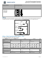
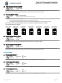
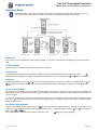
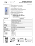
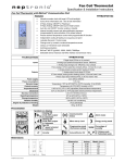
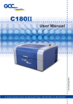
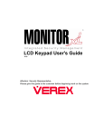
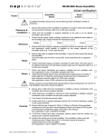
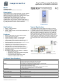
Fan Coil Thermostat Controller
Specification and Installation Instructions
Model
TFHB24F3XYZ2
with Humidity Sensor and BACnet Communication
Description
The TFHB24F3XYZ2 is a fully configurable controller designed
specifically for 2 pipe and 4 pipe fan coil applications. No
additional modules are required as the required inputs, outputs
and control algorithms are built into the unit. The
TFHB24F3XYZ2 also provides support for networked
communications via the BACnet MS/TP protocol. The
TFHB24F3XYZ2 also provides an internal humidity sensor to
dehumidify the controlled space when the humidity is too high
by cooling with the fan on low to create condensate.
TFHB24F3XYZ2
Applications
Typical Application
•
•
•
Fan coil applications provide heating and cooling to a zone by
circulating hot and cold air depending on the demand to maintain
an optimum temperature in the selected space. A fan coil setup
typically consists of fan coil units, source for hot and cold water,
and a pipe system for distribution. When there is a demand for
heating, the hot water is supplied to the unit through the source
and passes over the heating coil, and the hot air is pushed into
the zone by the fan. When there is a demand for cooling, the cold
water is supplied to the unit through the source and passes over
the cooling coil, and the cold air is pushed into the zone by the
fan.
Heating, cooling and reheat
2 pipes or 4 pipes
Auxiliary heating sources, such as electric baseboards, can
also be applied
Features
•
•
•
•
•
•
•
•
•
•
•
•
•
•
Backlit LCD with simple icon and text driven menus
Configurable inputs and outputs
2 Pipes with Analog, ON/OFF, or Floating option
4 Pipes with Analog, ON/OFF, or Pulse option
Internal humidity sensor and dehumidification sequence
(compensated by auto activation of reheat output)
Precise temperature control with programmable PI function
Selectable Fahrenheit or Celsius scale
Independent cool and heat setpoint for No Occupancy
Lockable setpoint, control mode, and fan mode
Selectable internal or external temperature sensor
Changeover by contact or external temperature sensor
Selectable proportional control band and dead band
Anti-freeze protection
BACnet® MS/TP @ 9600, 19200, 38400, or 76800 bps
o Selectable MAC address
o Automatic or manual device instance assignment
o Automatic baud rate detection
o Copy and broadcast configuration to other
networked TFHB24F3XYZ2 modules
* Consult www.neptronic.com for details on these Neptronic products.
Technical Specifications
Description
Inputs
Fan Coil Thermostat Controller
Outputs
1 Digital input (24Vac or dry contact)
1 Analog input (external temperature sensor 10Kohms)
1 Analog input (change over 10Kohms or dry contact)
1 Fan analog or 3 Fan speed dry contracts 24Vac, 1A max 3A in-rush)
2 Analog outputs (cooling and/or heating 0-10Vdc
1 Analog output (local reheat 0-10Vdc)
2 TRIAC outputs (cooling and/or heating) 24Vac, 0.3A max fused / TRIAC
1 TRIAC output (local reheat) 24Vac, 0.3 max fused TRIAC
Power supply
22 to 26Vac 50/60Hz
Power consumption
1VA max
Setpoint range
10ºC to 40ºC [50ºF to 104ºF], Humidity 10 to 65% RH
External sensor range
0ºC to 50ºC [32ºF to 122ºF]
Control accuracy
Temperature: ±0.4ºC [0.8ºF], Humidity: ±3.5%
Proportional band
0.5ºC to 5ºC [1ºF to 10ºF] adjustable (heat/cool/reheat independent)
Dead Band
0ºC to 5ºC [0ºF to 10ºF] adjustable (heat/cool/reheat independent)
Electrical connection
0.8 mm [18 AWG] minimum
TFHB24F3XYZ2-EBA-140113.docx
2
Fan Coil Thermostat Controller
Specification and Installation Instructions
Description
Fan Coil Thermostat Controller
Operating temperature
0ºC to 50ºC [32ºF to 122ºF]
Storage temperature
-30ºC to 50ºC [-22ºF to 122ºF]
Relative Humidity
5 to 95% RH non condensing
Degree of protection of housing
IP 30 (EN 60529)
Weight
160 g. [0.36 lb]
Dimensions
A = 2.85” | 73mm
B = 4.85” | 123mm
C = 1.00” | 24mm
D = 2.36” | 60mm
E = 3.27” | 83mm
B
E
D
ºF / º C
A
C
Wiring
We strongly recommend that all Neptronic products be wired to a separate grounded transformer and that transformer shall service
only Neptronic products. This precaution will prevent interference with, and/or possible damage to incompatible equipment.
Triac Output Signal Selector
(JP1)
JP1
ABC
TB1
2
Digital Output Signal
Selector (JP2)
1
A
B
C
JP2
3
4
5
6
Connecting Strip
(TB1)
8
9
JP4
A
B
C
10 11 12 13 14 15 16 17 18
A
B
C
PGM RUN
7
JP3
Mode Selector
(JP3)
Fan Output Signal
Selector (JP4)
Dip Switch
1 2 3
ON
Temperature Sensor
Wiring - 2 Pipe Terminal Description Details - 2 Pipe
For 2 pipe signal configuration, refer to step 9 on page 5.
For fan output configuration, refer to step 33 on page 8.
Terminals
Analog
On/Off
Floating
Step
1
Common
Common
Common
Common
-
2
24 Vac
24 Vac
24 Vac
24 Vac
-
3
TRIAC Input Voltage (ext.)
24 Vac (ext.): if JP1 is set to external
24 Vac (ext.): if JP1 is set to external
24 Vac (ext.): if JP1 is set to external
-
4
TRIAC Output 1 (TO1)
-
2 pipe on/off
2 pipe floating (close)
9
5
TRIAC Output 2 (TO2)
-
-
2 pipe floating (open)
9
6
TRIAC Output 3 (TO3)
Local reheat *
Local reheat *
Local reheat *
21
Fan
1 speed
2
speed
3
speed
Analog
1
speed
3
speed
Analog
1
speed
24 Vac (ext.): if JP2 is set to external
2
speed
3
speed
Analog
7
DO Input Voltage (ext.)
8
Digital Output 1 (DO1)
-
-
High
-
-
-
High
-
-
-
High
-
33
9
Digital Output 2 (DO2)
-
High
Med
-
-
High
Med
-
-
High
Med
-
33
10
Digital Output 3 (DO3)
Low
Low
Low
AO4
Low
Low
Low
AO4
Low
Low
Low
AO4
33
11
Digital Input 1 (DI1)
Occupancy Sensor *
Occupancy Sensor *
Occupancy Sensor *
12
Analog Input (AI1)
External Temp Sensor *
External Temp Sensor *
External Temp Sensor *
38
13
Analog Input (AI2)
External Changeover *
External Changeover *
External Changeover *
13
14
Analog Output 1 (AO1)
2 pipe analog
-
-
9
15
Analog Output 2 (AO2)
-
-
-
9
16
Analog Output 3 (AO3)
Local reheat *
Local reheat *
Local reheat *
21
17
A+
BACnet communication
BACnet communication
BACnet communication
-
18
B* optional
BACnet communication
BACnet communication
BACnet communication
-
www.neptronic.com
24 Vac (ext.): if JP2 is set to external
2
speed
24 Vac (ext.): if JP2 is set to external
Page | 2
Fan Coil Thermostat Controller
Specification and Installation Instructions
Wiring - 4 Pipe Terminal Description Details - 4 Pipe
For 4 pipe signal configuration, refer to step 15 and 18 on page 6.
For fan output configuration, refer to step 33 on page 8.
Terminals
Cool: Analog
Heat: Analog
Cool: On/Off
Heat: On/Off
Cool: Analog
Heat: On/Off or Pulse
Cool: On/Off
Heat: Analog
Step
1
Common
Common
Common
Common
Common
-
2
24 Vac
24 Vac
24 Vac
24 Vac
24 Vac
-
3
TRIAC Input Voltage (ext.)
24 Vac (ext.): if JP1 is set to external
24 Vac (ext.): if JP1 is set to external
24 Vac (ext.): if JP1 is set to external
24 Vac (ext.): if JP1 is set to external
-
4
TRIAC Output 1 (TO1)
-
4 pipe cool (on/off)
-
4 pipe cool (on/off)
9
5
TRIAC Output 2 (TO2)
-
4 pipe heat (on/off or pulse)
4 pipe heat (on/off or pulse)
-
9
6
TRIAC Output 3 (TO3)
Local reheat *
Local reheat *
Local reheat *
Local reheat *
21
Fan
1
speed
2
speed
3
speed
Analog
1
speed
2
speed
3
speed
Analog
1
speed
2
speed
3
speed
Analog
1
speed
2
speed
3
speed
Analog
7
DO Input Voltage (ext.)
24 Vac (ext.): if JP2 is set to external
24 Vac (ext.): if JP2 is set to external
24 Vac (ext.): if JP2 is set to external
24 Vac (ext.): if JP2 is set to external
8
Digital Output 1 (DO1)
-
-
High
-
-
-
High
-
-
-
High
-
-
-
High
-
33
9
Digital Output 2 (DO2)
-
High
Med
-
-
High
Med
-
-
High
Med
-
-
High
Med
-
33
10 Digital Output 3 (DO3)
Low
Low
Low
AO4
Low
Low
Low
AO4
Low
Low
Low
AO4
Low
Low
Low
AO4
33
11 Digital Input 1 (DI1)
Occupancy Sensor *
Occupancy Sensor *
Occupancy Sensor *
Occupancy Sensor *
12 Analog Input (AI1)
External Temp Sensor *
External Temp Sensor *
External Temp Sensor *
External Temp Sensor *
13 Analog Input (AI2)
-
-
-
-
13
14 Analog Output 1 (AO1)
4 pipe cool (analog)
-
4 pipe cool (analog)
-
18
15 Analog Output 2 (AO2)
4 pipe heat (analog)
-
-
4 pipe heat (analog)
15
16 Analog Output 3 (AO3)
Local reheat (analog)*
Local reheat (analog)*
Local reheat (analog)*
Local reheat (analog)*
21
17 A+
BACnet communication
BACnet communication
BACnet communication
BACnet communication
-
18 B* optional
BACnet communication
BACnet communication
BACnet communication
BACnet communication
-
-
Jumpers
Jumpers
Description
JP1
TRIAC Output Signal
Selector
A&B = Internal: All TRIAC output signals are linked to internal 24 Vac (same as thermostat).
B&C = External: All TRIAC output signals are linked to external 24 Vac (different than thermostat).
JP2
Digital Output Signal
Selector
A&B = Internal: All digital output signals are linked to internal 24 Vac (same as thermostat).
B&C = External: All digital output signals is linked to external 24 Vac (different than thermostat).
JP3
Mode Selection
A&B = RUN: Thermostat is in Operation Mode. (See Operation Mode Operation Modepage 13)
B&C = PGM: Thermostat is in Programming Mode. (See Programming Mode, page 4)
JP4
Fan Output Signal Selection
A&B: Pin 10 of TB1 is set to digital output signal (DO3). (See Step 33)
B&C: Pin 10 of TB1 is set to analog output signal (AO4). (See Step 33)
BACnet Dip Switch (DS1)
DIP Switches
1
2
3
ON
OFF
Not Used
-
-
End of Line
120 ohms
None
Not used
-
-
Mounting Instructions
B.
C.
D.
E.
CAUTION: Remove power to avoid a risk of malfunction.
A. Remove the captive screw that’s holding the base and the front cover of the unit together.
Lift the front cover of the unit to separate it from the base.
Pull all wires through the holes in the base.
Secure the base to the wall using wall anchors and screws (supplied). Make the appropriate connections.
Mount the control module on the base and secure using the screw.
A
www.neptronic.com
B
C
D
E
Page | 3
Fan Coil Thermostat Controller
Specification and Installation Instructions
Programming Mode
The Mode Selector Jumper JP3 must be set to the “PGM” mode (Programming Mode). Refer to Wiring on page 2. To
exit, set the Jumper JP3 back to the “RUN” mode (Operation Mode). All changes will be saved.
Setpoint and User Control
1.
“inside temper sensor offset”
Range:
Offset
Increment:
10.0 to 40.0ºC
Max. ± 5ºC
0.1ºC
[50.0 to 104.0ºF]
[0.2ºF]
Compare the displayed temperature reading with a known value from a thermometer. To offset or calibrate the sensor, use the
arrows key to set the desired temperature reading. This is useful for thermostats installed in areas where the temperature read
is slightly different than the room’s actual temperature. For example, a thermostat placed right under the air diffuser. If the
thermostat is set to use an external temperature sensor, (t10.0 at Step 38), the thermostat displays "OFF".
2. “adjust minimum user setpnt”
Default:
Range:
Increment:
15.0ºC
10.0 to 40.0ºC
0.5ºC
[59ºF]
[50 to 104ºF]
[1ºF]
In Operation mode, you cannot decrease the setpoint to less than the value that is set as the minimum user point. The
minimum value is restricted by the maximum value set at Step 3. In other words, the value that is set as the minimum cannot
be greater than the maximum value.
3. “adjust maximum user setpnt”
Default:
Range:
Increment:
30.0ºC
10.0 to 40.0ºC
0.5ºC
[86ºF]
[50 to 104ºF]
[1ºF]
In Operation mode, you cannot increase the setpoint to more than the value that is set as the maximum user point. The
maximum value is restricted by the minimum value set at Step 2. In other words, the value that is set as the maximum cannot
be less than the minimum value.
4. “user setpnt locked”
Default:
Range:
No (Unlocked)
Yes / No
If set to No, the user setpoint option is not locked and the user can adjust the desired setpoint temperature. If set to Yes, the
user setpoint option is locked and the user cannot set the desired setpoint temperature. A lock symbol appears indicating
that the setpoint is locked.
5. “adjust intern setpnt”
Default:
Range:
Increment:
22.0ºC
10.0 to 40.0ºC
0.5ºC
[72ºF]
[50 to 104ºF]
[1ºF]
Set the desired temperature setpoint within the defined range. If the setpoint option was locked in Step 4, a lock symbol is
displayed. The setpoint value is restricted by the minimum (Step 2) and maximum (Step 3) values. In other words, the setpoint
should be within in the range of minimum and maximum setpoints.
www.neptronic.com
Page | 4
Fan Coil Thermostat Controller
Specification and Installation Instructions
6. “adjust temper control mode”
Default:
Range:
Auto (Automatic)
Auto (automatic cooling and heating), ON (Cooling or Heating), Heat (Heating Only), Cool (Cooling Only)
Select the control mode that you want to authorize to the user. To authorize all the available modes, select Auto (Automatic
Mode). The cooling and heating symbols are also displayed.
7.
“enable on off control mode”
Default:
Range:
Yes (Enable)
Yes/ No
If you select Yes, the user can set the unit to “Off” via the Control Mode (see page 14 ). If you select No, the “Off” selection
does not appear in the Control Mode.
Pipe System Selection
8. “select 2 pipe 4 pipe system”
Default:
Range:
2P (2 pipe)
2P (2 pipe) / 4P (4 pipe)
Select the number of pipes that you want to use.
If you selected the 4 pipes option, go to Step 15.
9. “select 2 pipe signal”
Default:
Range:
AnLG (Analog)
AnLG (Analog), OnOf (On/Off), Flt (Floating)
Select the desired signal output for your 2 pipe system from the available options. The cooling
also displayed.
•
If you select analog signal, AO1 will be set to automatic heat/cool changeover.
•
If you select OnOf, TO1 will be set to automatic heat/cool changeover.
•
If you select Flt, TO1 will be set to close and TO2 will be set to open.
and heating
symbols are
If you selected AnLG (analog) signal, go to Step 11.
If you selected OnOf (on/off) signal, go to Step 13.
10. “set floating time in seconds”
Default:
Range:
Increment:
100 seconds
15 to 250 seconds
5 seconds
Select the desired value for the floating time signal and go to Step 13.
Outputs
11. “min vdc analog output”
Default:
Range:
Increment:
0.0 Volt
0.0 to 10.0 Volt
0.1 Volt
Select the desired minimum voltage (zero value) for the analog ramp. The minimum value (Step 11) is restricted by the
maximum value (Step 12). In other words, the minimum value should be less than the maximum value.
12. “max vdc analog output”
Default:
Range:
Increment:
10.0 Volt
0.0 to 10.0 Volt
0.1 Volt
Select the desired maximum voltage (span value) for the analog ramp. The maximum value (Step 12) is restricted by the
minimum value (Step 11). In other words, the maximum value should be greater than the minimum value.
www.neptronic.com
Page | 5
Fan Coil Thermostat Controller
Specification and Installation Instructions
13. “Ch over temper sensor”
Default:
Range:
SENs (external changeover sensor)
SENs, NoCl, NoHt
•
If SENs is selected: heating mode activates when the temperature read by the external sensor is above the
Changeover Setpoint and cooling mode activates when the temperature read by the external sensor is below the
Changeover Setpoint. (see Step 14)
•
If NoHt is selected: heating mode activates if the contact is opened and the cooling mode activates if the contact is
closed. (see Step 14)
•
If NoC is selected: heating mode activates if the contact is closed and cooling mode activates if the contact is open.
If you selected NoCl or NoHt option, go to Step 21.
14. “Ch over setpnt temper”
Default:
Range:
Increment:
24.0ºC
10.0 to 40.0ºC
0.5ºC
[75ºF]
[50 to 104ºF]
[1ºF]
This option appears if you have set one of the analog inputs to SENs (external changeover sensor) at Step 13. Set the desired
changeover temperature setpoint. Note that the heating mode activates when the temperature read by the external sensor is
above the changeover setpoint and cooling mode activates when the temperature read by the external sensor is below the
changeover setpoint.
Go to Step 21.
15. “select 4 pipe heating signal”
Default:
Range:
AnLG (Analog)
AnLG (Analog), OnOf (On /Off), PULs (Pulse)
This option appears if you have selected 4P at Step 8. Select the heating signal for your 4 pipe system.
•
If you select AnLG ((Analog), AO2 will be set to heating.
•
If you select OnOf (On/Off), or PULs (Pulse), TO2 will be set to heating.
If you selected OnOf or PULs signal, go to Step 18.
16. “min vdc analog output heating”
Default:
Range:
Increment:
0.0 Volt
0.0 to 10.0 Volt
0.1 Volt
Select the desired minimum voltage (zero value) for heating ramp. The minimum value (Step 16) is restricted by the maximum
value (Step 17). In other words, the minimum value must be less than the maximum value.
17.
“max vdc analog output heating”
Default:
Range:
Increment:
10.0 Volt
0.0 to 10.0 Volt
0.1 Volt
Select the desired maximum voltage (span value) for heating ramp. The maximum value (Step 17) is restricted by the minimum
value (Step 16). In other words, the maximum value must be greater than the minimum value.
18. “select 4 pipe cooling signal”
Default:
Range:
AnLG (Analog)
AnLG (Analog), OnOf (On/Off)
This option appears if you have selected 4P at Step 8. Select the desired cooling signal output for your 4 pipe system.
•
If you select the AnLG (analog) signal, AO1 will be set to cooling.
•
If you select the OnOf (on/off) signal, TO1 will be set to cooling.
If you selected the OnOf signal, go to Step 21.
19. “min vdc analog output cooling”
Default:
Range:
Increment:
0.0 Volt
0.0 to 10.0 Volt
0.1 Volt
Select the desired minimum voltage (zero value) for cooling ramp. The minimum value (Step 19) is restricted by the maximum
value (Step 20). In other words, the minimum value must be less than the maximum value.
www.neptronic.com
Page | 6
Fan Coil Thermostat Controller
Specification and Installation Instructions
20. “max vdc analog output cooling ”
Default:
Range:
Increment:
10.0 Volt
0.0 to 10.0 Volt
0.1 Volt
Select the desired maximum voltage (span value) for cooling ramp. The maximum value (Step 20) is restricted by the minimum
value (Step 19). In other words, the maximum value should be greater than the minimum value.
21. “set local reheat signal”
Default:
Range:
OFF (no signal selected)
OFF, AnLG, AnLG, On/Of, On/Of, PuLS, PuLS
Select the desired signal output for reheat.
•
If you select AnLG (Analog, heating and fan), AO3 will be set to reheat.
•
If you select On/Of (On/Off heating and fan) or PuLS (Pulse heating and fan), TO3 will be set to reheat.
If you selected On/Of (On/Off heating and fan), or or PuLS (Pulse heating and fan), go to Step 24.
If you selected OFF, go to Step 26.
OFF (no signal
selected)
On/Of (On/Off
heating only)
PuLS (Pulse
heating only)
AnLG (Analog,
heating only)
On/Of (On/Off
heating and fan)
PuLS ( Pulse
heating and fan )
AnLG (Analog,
heating and fan)
22. “min vdc analog output reheat”
Default:
Range:
Increment:
0.0 Volt
0.0 to 10.0 Volt
0.1 Volt
Select the desired minimum voltage (zero value) of reheat ramp. The minimum value (Step 22) is restricted by the maximum
value (Step 23). In other words, the minimum value must be less than the maximum value.
23. “max vdc analog output reheat”
Default:
Range:
Increment:
0.0 Volt
0.0 to 10.0 Volt
0.1 Volt
Select the desired maximum voltage (span value) of reheat ramp. The maximum value (Step 23) is restricted by the minimum
value (Step 22). In other words, the maximum value must be greater than the minimum value.
Control Ramps
24. “control ramp reheat”
Default:
Range:
Increment:
2.0ºC
0.5 to 5.0ºC
0.5ºC
[4ºF]
[1 to 10ºF]
[1ºF]
Select the desired value for the reheat proportional band. The heating
symbol is also displayed.
25. “control dead band reheat”
Default:
Range:
Increment:
0.3ºC
0 to 5.0ºC
0.1ºC
[0.6ºF]
[0 to 10.0ºF]
[0.2ºF]
Select the desired value for the reheat dead band. The heating
symbol is also displayed.
26. “control ramp HEATing”
Default:
Range:
Increment:
2.0ºC
0.5 to 5.0ºC
0.5ºC
[4ºF]
[1 to 10ºF]
[1ºF]
Select the desired value for the heating proportional band. The heating
www.neptronic.com
symbol is also displayed.
Page | 7
Fan Coil Thermostat Controller
Specification and Installation Instructions
27. “control ramp cooling”
Default:
Range:
Increment:
2.0ºC
0.5 to 5.0ºC
0.5ºC
[4ºF]
[1 to 10ºF]
[1ºF]
Select the desired value for the cooling proportional band. The cooling
symbol is also displayed.
28. “control dead band heating”
Default:
Range:
Increment:
0.3ºC
0 to 5.0ºC
0.1ºC
[0.6ºF]
[0 to 10.0ºF]
[0.2ºF]
Select the desired value for the heating dead band. The heating
symbol is also displayed.
29. “control dead band cooling”
Default:
Range:
Increment:
0.3 ºC
0 to 5.0ºC
0.1ºC
[0.6ºF]
[0 to 10.0ºF]
[0.2ºF]
Select the desired value for the cooling dead band. The cooling
symbol is also displayed.
Other Settings
30. “cooling anti cycle minutes”
Default:
Range:
Increment:
2 minutes
0 to 15 minutes
1 minute
To protect the compressor, set the delay in minutes before activating or reactivating the cooling contact. The cooling
is also displayed. The cooling symbol is also displayed.
symbol
31. “adjust intgral time in seconds”
Default:
Range:
Increment:
0 second
0 to 250 seconds
5 seconds
Select the desired value for the integration factor compensation.
32. “adjust damping factor seconds”
Default:
Range:
Increment:
0 second
0 to 10 seconds
1 second
Select the desired value for the damping factor. The fan
symbol and the cooling
symbol are also displayed.
Fan Settings
33. “select fan speed signal”
Default:
Range:
3 (speed fan contact)
1 (speed fan contact), 2 (speed fan contact), 3 (speed fan contact), AnLG (Analog)
Select the desired fan speed. If you have selected the speed fan contact option, select the speed, and go to Step 36. The fan
symbol is also displayed.
34. “min vdc analog output fan”
Default:
Range:
Increment:
0.0 Volt
0.0 to 10.0 Volt
0.1 Volt
Select the desired minimum voltage (zero value) for fan ramp. The minimum value (Step 34) is restricted by the maximum
value (Step 35). In other words, the minimum value should be less than the maximum value. The fan
symbol is also
displayed.
35. “max vdc analog output fan”
Default:
Range:
Increment:
10.0 Volt
0.0 to 10.0 Volt
0.1 Volt
Select the desired maximum voltage (span value) for fan ramp. The maximum value (Step 35) is restricted by the minimum
value (Step 34). In other words, the maximum value must be more than the minimum value. The fan
symbol is also
displayed.
www.neptronic.com
Page | 8
Fan Coil Thermostat Controller
Specification and Installation Instructions
36. “enable fan auto mode”
Default:
Range:
Yes (enabled)
Yes (enable), No (disable)
Select the Enable or Disable option to allow the user to adjust the Automatic mode. The fan
symbol is also displayed.
If you selected No (disable), go to Step 38.
37. “fan auto timeout minutes”
Default:
Range:
Increment:
2 minutes
0 to 15 minutes
1 minute
Select the desired value for the automatic shutoff delay. The fan
symbol is also displayed.
External Temperature Sensor
38. “extern sensor temper”
Default:
Range:
OFF (input none rewired)
OFF (input none rewired), t10.0 (external temperature sensor 10.0 KΩ)
Select the sensor that should be rewired to the analog output.
•
If you select OFF, the thermostat will be controlled by its internal temperature sensor.
•
If you select t10.0, the thermostat will be controlled by an external temperature sensor.
If you selected the OFF option, go to Step 40.
39. “extern temper sensor offset”
Offset:
Range:
Increment:
Max. ± 5ºC
0.0 to 50.0ºC
0.1ºC
[41.0 to 122.0ºF]
[0.2ºF]
This option appears if you have set one of the analog inputs to t10.0 (External temperature sensor 10.0 KΩ) at step 38. When
the thermostat is connected to the appropriate analog input (AI1 or AI2), the display shows the temperature read by the
external temperature sensor. Adjust the offset by comparing it with a known value (e.g. thermometer). If the sensor is not
connected or short circuited, the display is blank “Error“, and the error symbol
is displayed.
No Occupancy
40. “Select occ contact”
Default:
Range:
NO (Normally Open)
NO (Normally Open), NC (Normally Close)
Select the desired occupancy contact option. The moon
symbol is also displayed.
41. “no occ delay overide minutes”
Default:
Range:
Increment:
120 minutes
0 to 180 minutes
15 minutes
Select the desired derogation time. If you do not wish to select any time, set it to 0. The moon
symbol is also displayed.
42. “no occ heating setpnt”
Default:
Range:
Increment:
16.0ºC
10.0 to 40.0ºC
0.5ºC
[61ºF]
[50 to 104ºF]
[1ºF]
Select the desired heating setpoint temperature during the no occupancy period. The maximum value is restricted by the
cooling setpoint in the no occupancy period (Step 43). In other words, the maximum value must be greater than the no
occupancy cooling setpoint value. The moon and heating symbols are also displayed.
43. “no occ cooling setpnt”
Default:
Range:
Increment:
28.0ºC
10.0 to 40.0ºC
0.5ºC
[82ºF]
[50 to 104ºF]
[1ºF]
Select the desired cooling setpoint temperature during the no occupancy period. The minimum value is restricted by the
heating setpoint in the no occupancy period (Step 42). In other words, the minimum value must be less than the no occupancy
heating setpoint value. The moon and cooling symbols are also displayed.
www.neptronic.com
Page | 9
Fan Coil Thermostat Controller
Specification and Installation Instructions
Humidity Settings
44. “inside humidity sensor offset”
Offset:
Range:
Increment:
± 5%
10 to 90%
0.1%RH
Compare the displayed humidity percentage reading with a known value from a humidistat. This is useful for humidistats
installed in areas where the humidity read is slightly different than the rooms's actual humidity. For example, a humidistat
placed right under the air diffuser. The humidify symbol is also displayed.
45. “humidity control ramp”
Default:
Range:
Increment:
5.0% RH
3 to 10% RH
0.5% RH
Select the desired span for the humidity ramp. The humidify
symbol is also displayed.
Anti-Freeze
46. “enable anti freeze protect”
Default:
Range:
No (disabled)
No, Yes
If this option is enabled, heating starts automatically when the temperature drops to 4ºC [39ºF], even if the thermostat is in OFF
mode. Once the temperature reaches 5ºC [41ºF], the heating stops.
BACnet Settings
47. “auto BAUDS RATE”
Default:
Range:
Yes (enabled)
Yes (enable), No (disable)
Enable or disable Auto Baud Rate Detection. If you enable this option, the controller configures its baud rate automatically by
detecting the network speed upon connection to the network (go to Step 48). If you disable this option, you must select the
baud rate manually (go to Step 49).
48. “auto comport BAUDS RATE”
Default:
Range:
No default (information display only)
9600, 19200, 38400, 76800
If you enabled Auto Baud Rate Detection at Step 47, the display shows the baud rate that has been detected. Go to Step 50.
49. “adjust comport bauds rate”
Default:
Range:
9.6 kBps
9.6k, 192.k, 38.4k, 76.8k
If you disabled Auto Baud Rate Detection at Step 47, select the required baud rate manually.
50. “adjust MSTP Mac address”
Default:
Range:
Increment:
1
0 to 254
1
Select the desired MS/TP MAC Address. Each device on the network must have a unique MAC address.
51. “copy config”
Default:
Range:
No
Yes, No
Select Yes to copy the configuration of the existing device to other devices of the same type on the network. If you select No,
go to Step 55.
www.neptronic.com
Page | 10
Fan Coil Thermostat Controller
Specification and Installation Instructions
52. “Select begin address”
Default:
Range:
Increment:
0
0-254
1
Select the first address you want to copy to. For example, if you select MAC address 1 as the begin address and 54 as the end
address, all the devices from 1 to 54 will receive the configuration of the current device.
53. “Select end address”
Default:
Range:
Increment:
"begin address"
"begin address + 63"
1
Select the last address you want to copy to. You cannot copy more than 64 addresses at once.
54. “Copy config result”
Range:
“Copy Config” followed by one of these results:
“Succeed”, “Progerr”, “Typeerr”, “Modlerr”, “Memerr”, “Slave”, “Commerr”
Displays “Succeed” if the addresses have been copied successfully. Otherwise, an error message appears with the associated
MAC address. You can scroll through the addresses and see the error message associated with each address. The following is
a complete list of error messages:
"copy config succeed"
Copy config was successful.
“Copy Config” results
"copy config progerr"
Copy config failed because the target device is in Program Mode.
"copy config typeerr"
Copy config failed because the target device is not the same as the
source device. For example, copying a TRO configuration to a TFC
device.
MAC address of
associated device
Indicates
error
Use the arrow keys
to scroll through
each address
copy config modlerr"
Copy config failed because the model number of the source device and the target device is not the same. For example,
copying a TFCB24F3XYZ1 configuration to a TFC24F3YZ1.
"copy config mem err"
Copy config failed because the software/application version of the source device and the target device is not the same.
"copy config Slave"
The target device has a slave address and it cannot respond to the master. Manually verify that the configuration was copied
correctly or avoid using a slave address (128 - 254).
"copy config commerr"
Copy config failed because the target device did not respond after 3 attempts. Either the address does not exist or there is a
problem with the wiring or with noise.
55. “adjust device instanc 0153000”
Default:
Range:
No
No, Yes
To change the device instance, select Yes and continue to the next step. If you select No, the device instance will be modified
automatically according to the MAC address (the menu starts over at Step 1).
56. “0153000”
Default:
Range:
Increment:
"current value"
0 to 4194302
1
Use the arrow keys to change the value and press
to move to the next digit on the right or press
to move to the digit
on the left. Ensure that you provide a unique device instance. Set the Jumper (JP3) to "RUN" mode (Operation Mode) to save
the changes.
www.neptronic.com
Page | 11
Fan Coil Thermostat Controller
Specification and Installation Instructions
BACnet Setup Operation Mode
The BACnet Setup mode is accessible through the normal Operation mode.
1. The Mode Selector Jumper (JP3) must be set to the “RUN” mode (Operation Mode). Refer to Wiring on page 2.
2. Press the
and
keys for 5 seconds. The “Enter Password” screen appears.
3. Enter the password (637) within 1 minute. Use the arrow keys
and
to increase or decrease the value and the
,
to advance and return to the digits respectively. If you enter the wrong password, the thermostat displays “Eror” and returns to
Operation Mode.
4.
If you enter the password correctly, you will be taken to the BACnet program mode. The
symbol is displayed indicating that
the BACnet mode is active. In the BACnet mode, press the
key to advance to the next program function and the
to
return to the previous program function. Use the
and
keys to adjust the values.
The thermostat will return to normal mode if you navigate through the entire menu and do not make any selection, or if you do not
press any key for 5 minutes. The changed values will be saved automatically.
1.
"auto BAUDS RATE” to "adjust device instance"
Range:
Page:
Steps 47 to 56
Page 10 and 11
These BACnet setup steps are exactly the same as those in the Programming Mode. Please refer to Steps 47 to 56 starting on
page 10. When complete continue to the following step.
2. "INSIDE TEMPER SENSOR OFFSET"
Offset:
Range:
Increment:
Max. ± 5 ºC
10.0 to 40.0ºC
0.1ºC
[50.0 to 104.0ºF]
[0.2ºF]
Compare the displayed temperature reading with a known value from a thermometer. To offset or calibrate the sensor, use the
arrows key to set the desired temperature reading. This is useful for thermostats installed in areas where the temperature read
is slightly different than the room’s actual temperature. For example, a thermostat placed right under the air diffuser.
www.neptronic.com
Page | 12
Fan Coil Thermostat Controller
Specification and Installation Instructions
Operation Mode
The Mode Selector Jumper (JP3) must be set to the "RUN" mode (Operation Mode). Refer to Wiring on page 2. To
exit, set the Jumper (JP3) back to the "PGM" mode (Programming Mode). All changes will be saved.
Power Up
Upon power up, the LCD illuminates and all segments appear for 2 seconds. The thermostat then displays its current version for 2
secs.
LCD Backlight
Pressing any key on the thermostat illuminates the LCD for 4 seconds.
Temperature
The thermostat always displays the temperature reading. If the sensor is disconnected or short circuited then “OFF”, “- - -”,
(alarm symbol) are displayed. To toggle the temperature scale between ºC and ºF, press both the
and
keys for 3 seconds.
Setpoint
To display the setpoint, press the
or
key twice. The setpoint appears for 3 seconds. To adjust the setpoint, press the
and
keys while the temperature is displayed. If the setpoint adjustment has been locked (Step 4 on page 4), the lock symbol
appears.
No Occupancy Mode
This function is only available if you have selected the derogation time at Step 41 on page 9. If the no occupancy is triggered, the
thermostat enters the No Occupancy Mode (the symbol appears) and uses the heating and cooling setpoints defined at Step 42
and 43 on page 9.
The user can press any key to override the duration of No Occupancy. The symbol flashes to indicate that the derogation period
is on. If the symbol does not flash, it means that the derogation period is complete or that the No Occupancy Mode derogation
option has been locked.
Humidity Setpoint Mode
To access the Humidity Setpoint Mode, press the
key for 5 seconds. The mode appears for 5 seconds. The message, adjust
humidity setpoint is displayed indicating that the humidity mode is active. To adjust the setpoint, use the
and
keys. To exit the
mode, press
or
key.
If the humidity sensor is disconnected or short circuited then “OFF”, “- - -”,
(alarm symbol) are displayed.
www.neptronic.com
Page | 13
Fan Coil Thermostat Controller
Specification and Installation Instructions
Control Mode
To access the Control Mode, press the
key. The Control Mode appears for 5 seconds. These options can vary depending on
the options selected at Steps 6 and 7 on page 5.
• Auto (Automatic Cooling or Heating)
• Cooling only (on)
• Heating only (on)
• OFF
Fan Speed Selection Mode
To access the Fan Speed selection mode, press the
key. The mode appears for 5 seconds. These options can vary
depending on the fan speed signal and auto mode settings at Step 33 and Step 36 on page 9.
•
•
•
•
•
Automatic speed. This option is available if you have selected Yes (Enable) at Step 36 in Programming Mode.
Low speed
Medium speed
High speed
Off
www.neptronic.com
Page | 14
Notes
Recycling at end of life: please return this product to your Neptronic local distributor for recycling. If you need to find the nearest
Neptronic authorized distributor, please consult www.neptronic.com.
400 Lebeau blvd, Montreal, Qc, H4N 1R6, Canada
www.neptronic.com
Toll free in North America: 1-800-361-2308
Tel.: (514) 333-1433
Fax: (514) 333-3163
Customer service fax: (514) 333-1091
Monday to Friday: 8:00am to 5:00pm (Eastern time)