1
Macro-Tech 3600VZ Power Amplifier
Controls
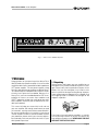
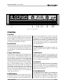
Enable: A front panel push button used to turn the amplifier on and off.
Level: A 31-position detented rotary attenuator for each
channel located on the front panel used to control the
output level.
Stereo/Mono: A three-position back panel switch used
to select Stereo, Bridge-Mono or Parallel-Mono operation.
Sensitivity: A three-position switch located inside the
PIP compartment used to select one of three input sensitivities for both channels: 0.775 volts or 1.4 volts for
standard 1 kHz power or a voltage gain of 26 dB.
Input Impedance: Nominally 20 k ohms, balanced.
Nominally 10 K ohms, unbalanced.
Input Sensitivity: Switchable between 0.775 V (unbalanced) for rated output or a fixed voltage gain of 26 dB.
(See subsection 4.4 for more information.)
Output Connector: Color-coded dual binding posts
(banana jacks).
Output Impedance: Less than 10 milliohms in series
with less than 2 microhenries. See Figure 6.5.
DC Output Offset: (Shorted input) ±10 millivolts.
Output Signal
Stereo: Unbalanced, two-channel.
Input Ground Lift: A two position back panel switch
used to isolate the phone jack signal grounds from the
chassis (AC) ground.
Bridge-Mono: Balanced, single-channel. Channel 1
controls are active; Channel 2 controls are inactive and
not removed from operation.
Reset: A back panel button for each channel used to
reset the corresponding power supply. 100 and
120 VAC units have 15 amp circuit breakers. 230 VAC
units have 7.5 amp circuit breakers.
Parallel-Mono: Unbalanced, single-channel. Channel
1 controls are active; Channel 2 controls are inactive
but not removed from operation.
Indicators
Protection
Enable: This amber indicator is on when the amplifier
is switched on to show that the low voltage power supply is operating.
Macro-Tech amplifiers are protected against shorted,
open or mismatched loads; overloaded power supplies;
excessive temperature, chain destruction phenomena,
input overload damage and high-frequency blow-ups.
They also protect loudspeakers from input/output DC
and turn-on/turn-off transients.
Signal / IOC: Two green indicators flash with medium
intensity in sync with the amplifier’s outputs to show signal presence. In the unlikely event the output waveform
differs from that of the input by 0.05% or more, they
flash brightly to indicate distortion. As sensitive distortion indicators they provide proof of performance. Note:
It is normal for the Channel 2 IOC indicator to remain on
in Parallel-Mono mode.
ODEP: Each channel has a multifunction LED (light
emitting diode) indicator that shows the channel’s energy reserve status. Normally, the LEDs are brightly lit
to show that reserve energy is available. In the rare
event that a channel has little reserve, its indicator dims
in proportion to ODEP limiting. An ODEP indicator may
also turn off under other, more unusual circumstances
(see Section 4.2).
Input/Output
Input Connector: Balanced ¼-inch phone jacks on
chassis and internal PIP connector. (Balanced 3-pin
XLR connectors are provided on the P.I.P.-FX which is a
standard feature.)
Page 30
If unreasonable operating conditions occur, the patented ODEP circuitry proportionally limits the drive level
to protect the output devices, particularly in the case of
elevated temperature. Transformer overheating results
in a temporary shutdown of the offending channel.
When it has cooled to a safe temperature, the transformer automatically resets itself. Controlled slew rate
voltage amplifiers protect against RF burnouts, and input overload protection is provided by current-limiting
resistance at the input.
Turn On: The four second turn-on delay prevents dangerous turn-on transients. Turn-on occurs at zero crossing of the AC waveform, so power sequencers are rarely
needed with multiple units. Note: The turn-on delay time
may be changed. Contact Crown’s Technical Support
Group for details.
Circuit Breaker: Circuit breaker current ratings vary
based on the AC operating power.
Reference Manual