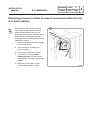
1
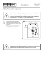
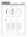
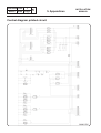
Installation manual
Ironers
IB42310 – IB42314 – IB42316
05405004/GB
13.10
.
INSTALLATION
MANUAL
05405004 0408
Table of contents
Notice
Date
0
Page
0
Pages/Chapters
Environmental information ..................................................................................... 1/1
Preliminary instructions ......................................................................................... 2/1
Note about the A.C. power .................................................................................... 3/1
Packaging .............................................................................................................. 1/2
Technical characteristics ........................................................................................ 1/3
Noise level ............................................................................................................. 3/3
Installation ............................................................................................................. 1/4
Work station lighting .............................................................................................. 2/4
Electrical connection .............................................................................................. 3/4
Check before use .................................................................................................. 8/4
Disconnecting the machine ................................................................................... 10/4
Releasing process ................................................................................................. 11/4
Safety thermostat's adjustment ............................................................................. 12/4
Star/Triangle Commutation .................................................................................... 15/4
Control diagram printed circuit ............................................................................... 1/5
Component implantation printed circuit ................................................................. 2/5
Convertion of measurements units ........................................................................ 3/5
The manufacturer reserves the right to modify construction and equipment characteristics.
05405004 1006
Notice
Date
1
Page
1
1. Preliminary instructions
INSTALLATION
MANUAL
Environmental information
Concerned by providing the end user with useful and necessary environmental information,
we wish to precise:
•
Data about energetic consumptions, wastes (atmospheric and liquid) and sound level are
indicated in the paragraph "Technical characteristics".
•
Forseeing its recycling, this machine is fully dismantable.
•
This machine is free from any asbestos.
•
In conformity with French regulations:
-
Law No. 76-663 of July 19th 1976 ;
-
Decree No. 77-1133 of September 21st 1977 ;
-
The decree of 7th July 1992 ;
-
The decree of 29th December 1993 ;
-
The decree of 28th December 1999 ;
-
No. 2311 of the nomenclature for classified installations.
Commerical linen cleaning laundries and launderettes are subject to:
•
-
prefectural authorisation if the washing capacity exceeds five tonnes per day,
-
a declaration to the prefecture if the washing capacity exceeds 500 kilos per day
but is below or equal to five tonnes per day.
In application of the Law of 15 July 1975 and the decrees of 01 April and 13 July 1994
on the disposal of industrial and commercial packing waste «All owners of packing waste
producing a weekly volume below 1100 litres can forward these to the local collection and
treatment department. If exceeding this volume, the owners of packing waste will ensure
their valuation by reuse, recycling or, any other action aiming at producing reusable
materials or energy... or provide them contractually to a certified intermediate authorised
to transport, trade or broke waste».
Therefore, these texts forbid:
•
-
land filling raw waste ;
-
open air burning or incineration without energy collection.
Packaging of our machines are according with the provisions of decree 98-638 from July
20 1998 related to environment requirements.
For additional information, do not hesitate to consult with our environmental department.
INSTALLATION
MANUAL
05405004 1206
1. Preliminary instructions
Notice
Date
2
Page
1
This machine should be installed in conformance to the health and safety regulations, and only used
in a sufficiently aerated area.
Check the instructions before installing or using the machine.
SAFETY
The mechanical and electrical installation
of the machine should only be done by
qualified personnel.
CAUTION
Do not use the machine unless it is
plugged into a correctly earthed power
socket complying with standards in force.
CAUTION
Make sure the machine is disconnected
from the mains before repairing or
servicing.
CAUTION
Any repairing or maintenance operation
should be carried out by a specialist.
05405004 0209
Notice
Date
3
Page
1
1. Preliminary instructions
INSTALLATION
MANUAL
Note about the A.C. power
According to the EN 60204-1:1997 standard, the machine is provided for AC supplies
corresponding to the extracted caracteristics below :
4.3.2 AC supplies
Voltage:
Steady state voltage: from 0.9 to 1.1 of nominal voltage.
Frequency:
from 0.99 to 1.01 of nominal frequency continuously.
from 0.98 to 1.02 short time.
Harmonics:
Harmonic distorsion not to exceed 10 % of the total r.m.s. voltage between live
conductors for the sum of the second through to the fifth harmonic. An additional 2 %
of the total r.m.s. voltage between live conductors for the sum of the sixth through to
the 30th harmonic is permissible.
Voltage unbalance:
Neither the voltage of the negative sequence component nor the voltage of the zero
sequence component in three-phase supplies shall exceed 2 % of the positive
sequence component.
Voltage interruption:
Supply interrupted or at zero voltage for not more than 3 ms at any random time in the
supply cycle. There shall be more than 1s between successive interruptions.
Voltage dips:
Voltage dips shall not exceed 20 % of the peak voltage of the supply for more than one
cycle. There shall be more than 1 second between successive dips.
INSTALLATION
MANUAL
05405004 0709
2. Packaging
Notice
Date
1
Page
2
The ironing machine is secured to a transport pallet and packaged in a cardboard box.
Ironing width
Packaging dimensions (boxed)
Lenght (A)
Width (B)
Height (C)
Weight
Units
1m
1.4m
1.6m
mm
mm
mm
kg
1480
540
1150
138
1880
540
1150
165
2130
540
1150
185
B
A
C
D0359
05405004 0209
Notice
Date
1
Page
3
3. Technical
characteristics
INSTALLATION
MANUAL
Neither base nor sealing are indispensable.
It is yet possible to fix the ironer to the floor.
To do so, use the holes made to block the machine on the transport pallet.
270
440
420
E
940
F
1025
510
A
B
C
07100017
05405004 0310
3. Technical
characteristics
INSTALLATION
MANUAL
Ironing width
Notice
Date
2
Page
units
1m
1.4 m
1.6 m
3
A
Overall length
mm
1395
1795
2045
B
Length of feeding table
mm
1000
1400
1650
Cylinder diameter
mm
230
230
230
Distance between feet
mm
1220
1620
1870
Evacuation diameter
mm
nothing
36/40
36/40
Electrical connection
-
see table
see table
see table
Main voltage
V
Frequency
Hz
see table
50/60
see table
50/60
see table
50/60
see table
7.50
see table
8.70
C
E
Power supply cable
mm²
Electric power, total load
kW
see table
5.20
Electric heating power
kW
5.00
7.20
8.40
kWh/h
4.28
5.82
7.27
Max. water evaporation capacity*
l/h
5.00
6.78
8.05
Heat loss
W
150
225
260
Control fuse (250 V)
A
1.25
1.25
1.25
Movement motor power
kW
0.18
0.18
0.18
Fan motor power
kW
0.06
0.06
m/min
nothing
3.4 (4)
3.4 (4)
3.4 (4)
Heating surface
m²
0.164
0.230
0.270
Weight
kg
120
140
165
Max. hourly consumption
F
Ironing speed at 50 (60) Hz
Ironing
width
Supply
voltage
Rated
intensity
Main switch
Connection cable
section
Fuse
1m
400/415 V 3+N+E ~ 50/60 Hz
7.4 A
4 x 20 A
5 x 2.5 mm²
10 A
1m
400/415 V 3+E ~ 50/60 Hz
7.4 A
3 x 20 A
4 x 2.5 mm²
10 A
1m
230/240 V 3+E ~ 50/60 Hz
12.8 A
3 x 20 A
4 x 2.5 mm²
16 A
1m
200/208 V 3+E ~ 50/60 Hz
14.8 A
3 x 20 A
4 x 2.5 mm²
16 A
1m
440/460 V 3+E ~ 50/60 Hz
6.7 A
3 x 20 A
4 x 2.5 mm²
10 A
1m
230 V mono 2+E ~ 50/60 Hz
23.2 A
2 x 32 A
3 x 6 mm²
35 A
1m
208 V 2+E ~ 50/60 Hz
25 A
2 x 32 A
3 x 6 mm²
35 A
1.4 m
400/415 V 3+E ~ 50/60 Hz
10.7 A
4 x 20 A
5 x 2.5 mm²
16 A
1.4 m
400/415 V 3+N+E ~ 50/60 Hz
10.7 A
3 x 20 A
4 x 2.5 mm²
16 A
1.4 m
230/240 V 3+E ~ 50/60 Hz
18.5 A
3 x 25 A
4 x 2.5 mm²
25 A
1.4 m
200/208 V 3+E ~ 50/60 Hz
21.3 A
3 x 25 A
4 x 2.5 mm²
25 A
1.4 m
440/460 V 3+E ~ 50/60 Hz
9.7 A
3 x 20 A
4 x 2.5 mm²
16 A
1.4 m
230 V mono 2+E ~ 50/60 Hz
33.6 A
3 x 40 A
3 x 6 mm²
50 A
1.6 m
400/415 V 3+N+E ~ 50/60 Hz
12.5 A
4 x 20 A
5 x 2.5 mm²
16 A
1.6 m
400/415 V 3+E ~ 50/60 Hz
12.5 A
3 x 20 A
4 x 2.5 mm²
16 A
1.6 m
208 V 3+E ~ 60 Hz
23 A
3 x 32 A
4 x 6 mm²
35 A
1.6 m
240 V 3+E ~ 60 Hz
20 A
3 x 25 A
4 x 6 mm²
25 A
1.6 m
440 V 3+E ~ 50/60 Hz
11.5 A
3 x 20 A
4 x 2.5 mm²
16 A
* With 20 % residual moisture content and 100 % roller utilization (according to ISO 93.98 standard).
3
05405004 1006
Notice
Date
Page
3. Technical
characteristics
3
INSTALLATION
MANUAL
Noise level
Airborne noise emitted by the machine (values established as from measurements made on
the machine at points A,B,C,D).
D0267
Ironing width
Weighted acoustic pressure
level (A) in dB(A)
Point A
Point B
Point C
Point D
1m
52
57
52
59
1.4 m
54
57
52
59
1.6 m
54
57
52
59
This ironing machine should only be used for previously washed and pre-dried,
machine-ironable textiles.
In this normal case of use, it is not necessary to connect the exhaust duct to the
open air.
In the opposite case, the exhaust duct must be connected to the open air, by the shortest
way, and with as few bents as possible.
Incline the flexi-hose downwards, as compared to the machine.
Protect the end of the exhaust duct from the bad weather.
Do not connect the exhaust duct to a gas, coal, fuel oil furnaces chimney. Separate it also
from any other ducting (tumble dryer, finishing cabinet...).
INSTALLATION
MANUAL
05405004 0209
4. Installation
Notice
Date
1
Page
4
Installation
The ironer must be transported to its final position in the laundry before the pallet is
removed.
Remove the cardboard box and the two side panels (key included).
Fig.
1
Remove the 2 fixing screws (1 screw
per casing) which fix the machine to
the transport pallet, and unload the
machine.
1
D0344
Fig.
2
Install the ironer in an area where it is
easilly accessable by both operators
and service technicians.
2
Make sure that the side of the machine
is at least 100 cm away from walls or
other machines.
In addition, leave a minimum of 10 cm
between the machine and any rear wall.
D0356
05405004 0209
Notice
Fig.
3
Date
2
Page
4
4. Installation
INSTALLATION
MANUAL
Install the four adjustable feet and counternuts delivered with the machine as shown on the
Fig. 3 below.
Place the machine on a perfectly stable and level floor. Check the horizontality of the
machine using a spirit level at both its centre and ends.
If required, use the adjustable feet to level the machine then lock with the counternuts.
Control the floor space (E) between the two casings in order for the treadle to move correctly.
Control manually the functionning of the pedal which has to move freely with no jamming.
3
E
D0345
Work station lighting
Lighting should be designed and installed so as to prevent operator eye fatigue (good all
over uniform lighting without bothersome glare) and provide a correct working light.
The average lighting recommended by European organisations is 300 lux.
The work station should have as much natural lighting as possible.
INSTALLATION
MANUAL
05405004 0408
4. Installation
Notice
Date
3
Page
Electrical connection
CAUTION
Prior to use, the machine should be
plugged into a correctly earthed power
socket complying with the standards in
force.
SAFETY
The mechanical and electrical installation
of the machine should only be done by
qualified personnel.
CAUTION
Make sure that both the power voltage
is correct and the power supply of your
installation is sufficient before connecting
the machine.
Use only a cable to supply the machine.
Connect the machine to a four-pole switch and protective fuses (customer supply).
The openning distance of the four-pole switch contact should be 3 mm minimum.
The values of these apparatus are indicated in chapter 3 -technical characteristics.
Install the main switch in an easily accessible position.
Insert the power cable into the stuffing box provided for this purpose.
4
4
05405004 0408
Notice
Date
Page
4
Three-phase connection
3N AC + E (PE)
Fig.
4
4. Installation
INSTALLATION
MANUAL
4
Connect the machine's power cable to
the terminal block on the printed circuit
provided for the purpose.
L1
Phase no 1
L2
Phase no 2
L3
Phase no 3
N
Neutral
PE
Earth connection
F1
Control fuse to protect the
electrical control circuit (1.25 A).
D0363
Three-phase connection
3 AC + E (PE)
Fig.
5
5
Connect the machine's power cable to
the terminal block on the printed circuit
provided for the purpose.
L1
Phase no 1
L2
Phase no 2
L3
Phase no 3
PE
Earth connection
F1
Control fuse to protect the
electrical control circuit (1.25 A).
D1585
INSTALLATION
MANUAL
05405004 0909
4. Installation
Single-phase connection
1N AC + E (PE)
Fig.
6
Notice
Date
5
Page
4
6
Connect the machine's power cable to
the terminal block on the printed circuit
provided for the purpose.
L1
Phase no 1
N
Neutral
PE
Earth connection
F1
Control fuse to protect the
electrical control circuit (1.25 A).
D1586
Single-phase connection
1 AC + E (PE)
Fig.
7
7
Connect the machine's power cable to
the terminal block on the printed circuit
provided for the purpose.
L1
Phase no 1
L2
Phase no 2
PE
Earth connection
F1
Control fuse to protect the
electrical control circuit (1.25 A).
D1587
05405004 0408
Notice
Date
6
Page
4
Mains transformer connection diagrams according
to the customer's various mains voltages
(machines equiped with a transformer only).
8
0
400 Volts supply
Fig.
8
INSTALLATION
MANUAL
4. Installation
+15
400
-15 230
Measure the mains voltage at the
primary with a voltmeter between 0 and
400 volts of the transformer.
- If the voltage is equal to 400 volts, do
not touch the transformer connection
which should be as indicated in the
margin.
U=400 V
D0333
Fig.
9
- If the voltage is > à 400 volts (example:
420/430 volts), connect the threads
to the transformer as indicated in the
margin.
9
+15
Note : the latter solution is advised
even it the voltage is normally equal
to 400 Volts, but may be subject
to time variations ; your machine
electrical equipment will not be
overfed.
400
0 -15 230
U>400 V
D0334
Fig.
10
- If the voltage is far < 400 volts
(example: 370/380 volts), connect the
threads to the transformer as indicated
in the margin.
10
-15
+15 0
400
230
U<400 V
D0338
05405004 0408
INSTALLATION
MANUAL
4. Installation
Notice
Date
7
Page
4
NB:
Once connected, make sure to check the correct order of phase connections.
CAUTION
If the phases are not connected the right order, when switching on the machine,
the bed remains in contact against the cylinder, this last rotates clockwise (see
from the machine right side), but the safety hand device is inoperative. You must
not, in any case, continue to operate the ironer. Stop the machine and invert the
phases.
05405004 0408
Notice
Date
8
Page
4
4. Installation
INSTALLATION
MANUAL
Check before use
Fig.
11
The ironing machine is delivered with
the tray in contact with the cylinder.
11
1. Check that the machine’s on/off
switch is to "0".
2. Turn on the main switch of the
machine.
D0347
Fig.
12
3. Push on the "on/off" button, the
green light is on, 4 cases (A, B, C or
D) can now arise.
12
D0349
CAUTION
The control pedal must not be operated before making the following checks.
05405004 0408
INSTALLATION
MANUAL
4. Installation
Notice
Date
9
Page
4
If the functionning of the machine does not correspond to either case (A) or (B), stop the
machine with the On/off switch (Fig.8), put the main switch to off and invert the 2 phase wires
on the power supply terminal block (Fig.4).
A
B
Phases in good order and bed closed
Phases in good order and bed opened
When starting up the ironer, the cylinder does
not rotate and the bed moves away from the
cylinder.
When starting up the ironer, the cylinder does
not rotate and the bed does not move.
Everything is OK.
You can operate the machine.
Everything is OK.
You can operate the ironer.
C
D
Inverted phases and bed closed
Inverted phases and bed opened
When starting up the ironer, the bed remains
closed, the cylinder rotates the right way but
the hand safety device is inoperative.
When starting up the ironer, the cylinder
rotates the wrong way and the bed blocks in
rear position.
Do not use the machine.
Release the bed and modify the phases order
(see below and next page).
Modify the phases order (see below)
•
Repeat operations points 1, 2 and 3, the tray should now move back.
•
Turn the main switch off.
•
Reinstall the side panels and lock the fixing screws.
•
Remove the protective paper from around the cylinder.
•
The ironing machine is now ready to be used.
Nota: At the first use, it is necessary to leave the cylinder heated turn for about one hour to allow the
padding to ram. This running in allows to get a space between the tray and the cylinder in order to feed
the linen easily.
05405004 0408
Notice
Date
10
Page
4
4. Installation
INSTALLATION
MANUAL
Disconnecting the machine
N B:
If you wish to disconnect the electrical supply cable, it si more wise to do it once
the machine is cooled down and to stop the ironer with the tray in contact with the
cylinder.
Fig.
13
Proceed as follows :
•
When the tray is cold, move it
against the cylinder by pressing on
the control pedal and activate the
on/off switch to stop the electrical
supply.
•
Stop the electrical supply by the
main switch.
•
You can now disconnect the
electrical sypply cable.
•
To reconnect the machine, it is
imperative to check the order of
connection of the phases before
starting the ironer (see previous
page).
13
D0347
INSTALLATION
MANUAL
05405004 0408
4. Installation
Notice
Date
11
Page
4
Releasing process to follow in case of connection while the tray
is in back position.
Fig.
14
If you connect the machine with the
tray in back position and the control
pedal activated (when two wires of
phase are inverted), an electrical device
doubled with a mechanical system of
locking prevents to deteriorate essential
mechanism organs.
14
1. Stop the machine's electrical supply
by the main switch.
2. Invert two wires of phase (see
previous page).
3. Remove the right lateral casing.
4. Unscrew the screw (A) while
holding the tray, this last comes
automatically in position against the
cylinder.
5. Block the screw again (A) and
reassemble the lateral casing.
D0389
05405004 0408
Notice
Date
12
Page
4
4. Installation
INSTALLATION
MANUAL
Safety Thermostat’s adjustment
This ironer has a an adjustable safety thermostat in order to avoid damages of the
cotton covering in case of machine stop with the bed closed.
This safety thermostat is adjusted in our plant so that the regulation thermostat
doesn’t go above the temperature corresponding to the position
aproximatly 150 °C ; even when it is set on a higher temperature.
Fig.
15
If you want to increase the ironing
temperature, dismantle the bed’s back
casing and turn the rod (T) of the safety
thermostat.
which is
15
This way, you can limit the maximum
ironing temperature as you want.
D0561
Check-out
Before leaving, put the appliance into operation and allow to run a complete cycle.
Watch to ensure that all burner system components function correctly.
INSTALLATION
MANUAL
05405004 0408
4. Installation
Notice
This page is left blank purpose.
Date
13
Page
4
05405004 0408
Notice
Date
14
Page
4
4. Installation
INSTALLATION
MANUAL
36000168
INSTALLATION
MANUAL
05405004 0408
5. Appendices
Notice
Star/Triangle Commutation diagram
A
B
P1
C1
Heating resistor commutation
Motion motor commutation
"Star" commutation from 380 to 460 volt three-phases
"Triangle" commutation from 200 to 240 volt three-phases
Commutation from 200 to 240 volt monophase
Phase shifting capacitor
Date
15
Page
4
05405004 1006
Notice
Date
1
Page
5
5. Appendices
INSTALLATION
MANUAL
Control diagram printed circuit
36000172C
INSTALLATION
MANUAL
05405004 1006
5. Appendices
Notice
Date
2
Page
5
Component implantation printed circuit
PLASTRON = PANEL CONTROL
BARRE = BAR
CUV. = BED
MONNAYEUR = COIN OPERATING SYSTEM
MOTEUR = MOTOR
CHAUFFAGE = HEATING
VENT. = VENTILATOR
PEDALE = PEDAL
36000173B
05405004 1006
Notice
Date
3
Page
5
5. Appendices
INSTALLATION
MANUAL
Conversion of measurement units
The following is a list of correspondences of the main frequently used units, to avoid the
need to use measurement unit conversion tables.
bar :
1 bar = 100 000 Pa
1 bar = 1.019 7 kg/cm²
1 bar = 750.06 mm Hg
1 bar = 10 197 mm H2O
1 bar = 14.504 psi
british thermal unit :
calorie :
1 kg/cm² = 10 000 mm H2O
1 kg/cm² = 735.557 6 mm Hg
pound :
1 lb = 453.592 37 g
meter :
1 m = 1.093 61 yd
1 m = 3.280 83 ft
1 m = 39.37 in
1 Btu = 1 055.06 J
1 Btu = 0.2521kcal
1 cal = 4.185 5 J
1 cal = 10-6 th
1 kcal = 3.967 Btu
1 cal/h = 0.001 163 W
1 kcal/h = 1.163 W
cubic meter :1 m³ = 1 000 dm³
1 m³ = 35.314 7 cu ft
1 dm³ = 61.024 cu in
1 dm³ = 0.035 3 cu ft
pascal :
1 Pa = 1 N/m²
1 Pa = 0.007 500 6 mm Hg
1 Pa = 0.101 97 mm H2O
1 Pa = 0.010 197 g/cm²
1 Pa = 0.000 145 psi
1 MPa = 10 bar
cubic inch : 1 cu in = 16.387 1 dm³
psi :
1 psi = 0.068 947 6 bar
foot :
thermie :
1 th = 1 000 kcal
1 th = 106 cal
1 th = 4.185 5 x 10⁶ J
1 th = 1.162 6 kWh
1 th = 3 967 Btu
continental horse power :1 ch = 0.735 5 kW
1 ch = 0.987 0 HP
cubic foot : 1 cu ft = 28.316 8 dm³
1 cu ft = 1 728 cu in
1 ft = 304.8 mm
1 ft = 12 in
gallon (U.K.) :
gallon (U.S.A.) :
horse power :
1 gal = 4.545 96 dm3 or l
1 gal = 277.41 cu in
1 gal = 3.785 33 dm3 or l
1 gal = 231 cu in
1 HP = 0.745 7 kW
1 HP = 1.013 9 ch
inch :
1 in = 25.4 mm
joule :
1 J = 0.000 277 8 Wh
1 J = 0.238 92 cal
kilogramme :1 kg = 2.205 62 lb
kg/cm2 :
1 kg/cm² = 98 066.5 Pa
1 kg/cm² = 0.980 665 bar
watt :
1 W = 1 J/s
1 W = 0.860 11 kcal/h
watt-hour : 1 Wh = 3600 J
1 kWh = 860 kcal
yard :
1 yd = 0.914 4 m
1 yd = 3 ft
1 yd = 36 in
temperature degrees :
0 °K = -273.16 °C
0 °C = 273.16 °K
t °C = 5/9 (t °F-32)
t °F = 1.8 t °C + 32
.
.
.
www.electrolux.com/laundrysystems
Share more of our thinking at www.electrolux.com