1
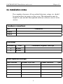
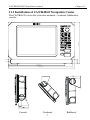
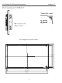
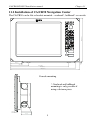
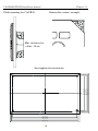
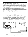
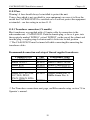
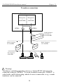
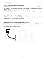
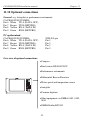
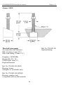
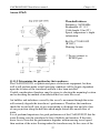
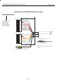
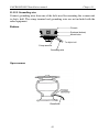
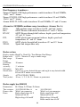
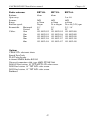
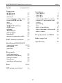
M A N U A L SIMRAD CA/CR40/42/50/52 Installation manual 183-0512-702 English 02244.30 CA/CR40/42/50/52 Installation and service manual Table of contents 11. Installation and service 11. Installation notes........................................................................... 5 11.1 Installation of CA/CR40/42......................................................... 7 11.2 Installation of CA/CR50 ............................................................... 9 11.3 Installation of CA/CR52 ............................................................. 11 11.4 Place of installation of display unit............................................. 13 11.5 Installation of RS4050 ................................................................ 13 11.6 Installation of DS40/42/50/52..................................................... 14 11.6.1 Operation of DS40/42/50/52 .................................................... 15 11.7 Installation of GPS / DGPS antenna ........................................... 16 11.8 Electrical connections ................................................................. 17 11.8.1 Power supply connections........................................................ 18 11.8.2 Fuse .......................................................................................... 19 11.8.3 Transducer connections............................................................ 19 11.8.4 NMEA0183 interface connections ........................................... 21 11.8.5 PC up/download via NMEA connection.................................. 21 11.9 Universal connection cable (optional) ........................................ 21 11.10 Optional connections .................................................................. 22 11.11 Basic transducer & cable information (CA models).................. 23 11.11.1 Transducers (optional) ............................................................. 24 11.11.2 Position for the transducer ....................................................... 27 11.12 Installation of scanner unit.......................................................... 29 11.12.1 Shifting away from obstacles ................................................... 30 11.12.2 Mounting of scanner ................................................................ 31 11.12.3 Connecting cables .................................................................... 35 11.12.4 Connector’s pin numbers and wire colors................................ 41 11.12.5 Grounding wire ........................................................................ 43 11.12.6 Adjustment .............................................................................. 44 11.13 Specifications.............................................................................. 44 Index .................................................................................................... 49 List of Simrad distributors CA/CR40/42/50/52 Installation and service manual Table of contents CA/CR40/42/50/52 Installation and service Chapter 11 11. Installation notes For a number of reasons, all user-related decisions, setups, etc. should be noted in these two pages as they occur. This information may be helpful if your unit has been updated with new software, reset or in for service. Transducer connections: Port Transducer ECHO1 ECHO2 Echo setup: Transducer Port 1 ECHO 2 ECHO Transducer frequency and type Other important settings: Radar antenna Scanner Type: RB 5 Scanner Rotation: rpm CA/CR40/42/50/52 Installation and service Chapter 11 Other important settings (continued): 6 CA/CR40/42/50/52 Installation manual Chapter 11 11.1 Installation of CA/CR40/42 Navigation Center 2 4 5 (9 .6 ) The CA/CR40/42 can be flat or bracket mounted – overhead, bulkhead or console. 2 5 (1 .0 ) 1 1 (0 .4 ) 5 2 (2 .1 ) 3 1 2 (1 2 .3 ) 3 5 4 (1 3 .9 ) 3 6 5 (1 4 .4 ) Console Overhead 7 Bulkhead CA/CR40/42/50/52 Installation manual Chapter 11 Flush mounting for CA/CR40/42: Removable corner. Min. clearance for cables: 15 cm. 192 202 208 220 (7 .6 ) (7 .9 ) (8 .2 ) (8 .7 ) See template for instructions! 337 347 353 365 (1 3 .3 ) (1 3 .7 ) (1 3 .9 ) (1 4 .4 ) 8 CA/CR40/42/50/52 Installation manual Chapter 11 11.2 Installation of CA/CR50 Navigation Center 2 9 5 (1 1 .6 ) The CA/CR50 can be flat or bracket mounted – overhead*, bulkhead* or console. 9 (0 .4 ) 7 4 (2 .9) 1 1 6 (4 .6 ) 3 7 6 (1 4 .8 ) 4 1 9 (1 6 .5 ) 4 4 5 (1 7 .5 ) Console mounting 1 96 (7 .7) * Overhead and bulkhead mounting is only possible if using a distance piece. 2 0 (0.8) 7 5 (3.0) 9 CA/CR40/42/50/52 Installation manual Chapter 11 Flush mounting for CA/CR50: Removable corners, example: Min. clearance for cables: 18 cm. 2 63 27 3 28 3 2 95 (10 .4 ) (10 .7) (11 .1 ) (11 .6 ) See template for instructions: 41 3 42 3 43 3 44 5 (1 6.3 ) (1 6.7 ) (1 7.0 ) (1 7.5 ) 10 CA/CR40/42/50/52 Installation manual Chapter 11 11.3 Installation of CA/CR52 Navigation Center 9 .2 (0 .4 ) 3 3 0 (1 3 ) The CA/CR52 can be flat or bracket mounted – overhead*, bulkhead* or console. 8 8 .8 (3.5 ) 1 3 1 .6 (5 .2 ) 3 9 1 .6 (1 5 .4 ) 4 3 3 .9 (1 7 ) 4 6 0 (1 8 .1 ) Console mounting 1 96 (7 .7) * Overhead and bulkhead mounting is only possible if using a distance piece. 2 0 (0.8) 7 5 (3.0) 11 CA/CR40/42/50/52 Installation manual Chapter 11 Flush mounting for CA/CR52: Removable corners, example: Min. clearance for cables: 18 cm. 2 97 .9 (11 .7 ) 30 7.9 (1 2.1 ) 31 8 (12 .5 ) 3 30 (13 ) See template for instructions: 42 7 .9 (1 6 .8 ) 43 7 .9 (1 7 .2 ) 44 8 (1 7.6 ) 46 0 (1 8.1 ) 12 CA/CR40/42/50/52 Installation manual Chapter 11 11.4 Place of installation of display unit The display unit can be installed on desktop, wall surface, or ceiling. Determine the place to install the display unit that is convenient for navigation and radar operation after considering the following suggestions: - there is a minimum clearance at the back of the unit of 15 cm (CA/CR40/42) or 18cm (CA/CR50/52). - you can see the ship’s bow when you raise your eyes from the display. - there is limited exposure to direct sunlight - see environment temperature limits in section 11.13 Specifications. - there is good ventilation and minimum vibration. - there is a minimum distance of 50 cm to a magnetic compass. 11.5 Installation of Radar supply box RS4050 The external power supply, RS4050, must be connected to the CA/CR40/42/50/52 to run the radar function. Dimensions: H:125mm, L:222mm, D:81mm. Connect power cable with 3 or 4 pin connector to the receptacle marked ‘PWR’ at the rear of the display unit, and the second 1.5m cable with 6-pin to the receptacle between ‘ANT’ and ‘ALARM’ at the rear of the display unit. ) 2 variants, refer to RS4050 addendum: 183-0700-001 or 183-0700-003. White Brown Yellow Grey Green AN T WIND AL AR M N M E A2 N M E A1 E CH O1 E CH O2 R A DAR P WR Cable to ship’s mains: 2x1.5 mm, max. 5 m long (not included). 13 CA/CR40/42/50/52 Installation manual Chapter 11 11.6 Installation of Dual Station DS40/42/50/52 The DS models are remote control units for the CA/CR40/42/50/52 main units. The units with the same model numbers are identical in size e.g. DS42 and CR42 so the same installation guides can be used when performing the installation. When choosing a dual station, the unit does not have to match the main unit in size, as all the mentioned units are compatible. CA/CR40/42/50/52 AN T W IND AL AR M N M E A2 N M E A1 E CH O 1 E CH O 2 R AD A R DS40/42/50/52 PWR AN T W IND AL AR M NM E A2 NM E A1 E CH O 1 E CH O 2 R AD AR PWR Power Ground 15 meters of cable (not extendable) Ground Power A special connection cable of 15 meters with two male plugs is supplied with the dual station. Push one of the male plugs into the receptacle marked NMEA1 on the back of the main unit and the second into the dual station. The NMEA1 interface from the main unit is transferred to the dual station via the connection cable and is available on the dual station’s NMEA2 receptacle. ) Refer to section 11.8 for details on pin numbers. 14 CA/CR40/42/50/52 Installation manual Chapter 11 The connection cable between the dual station and the main unit is a special pairtwisted cable of 15 meters (not extendable), which consists of the following wires: 104.3002.023 11.6.1 Operation of DS40/42/50/52 Dual Station The main unit and the dual station operate in parallel. All key commands are relayed to the main unit – CA/CR40/42/50/52 – and the display picture is instantly transferred back via a high speed data link. Adjust light/contrast in screen and background light in keypad via the [PWR] key. Eject keys and cartridge drawers are blinded, and can not be opened on the dual station. 15 CA/CR40/42/50/52 Installation manual Chapter 11 11.7 Installation of the GPS / DGPS antenna The antenna must be placed in a position where tall constructions, steel wires, masts, etc. do not obstruct the view to the satellites. Do not, however, mount the antenna in the top of a mast or tower, as this may degrade the COG and SOG readings, especially if DGPS is used. Do not place the antenna close to sources of electrical interference, such as radar, satcom, etc. If installing the GPS antenna close to other antennas it must be placed either above or below the radiation beams. There is full coverage down to 20° below the horizon. Satcom VHF Radar Beam area – avoid installing the GPS antenna inside the beam areas. Mounting of DGPS antenna MGL-3 Mount the antenna on a standard US 1” 14 thread pipe, or optional standard antenna mount. Tighten firmly, but only by hand – no use of tools. Attach the antenna cable to the TNC socket. 5 6 7 2 1 3 4 Mounting of GPS antenna RS5640 Loosen the screw (1) of the antenna adapter. Guide the antenna cable (2) through the adapter and connect it to the antenna. Screw the US 1” 14 mount adapter (3) firmly onto the optional antenna mount (4). Press (5) the antenna into the adapter and turn it (6) approx. ½ to 1 turn counter clockwise to “catch” the thread. Turn (7) clockwise 1 to 2 turns and firmly secure the antenna with the lock screw (1). ) Do not close the small ventilation hole at the bottom, and do not attempt to open the antenna. 16 CA/CR40/42/50/52 Installation manual Chapter 11 11.8 Electrical connections (connectors, seen from solder side) The PWR receptacle will accommodate either 3 or 4 pin connectors, depending on model and version. (The ECHO2 port is sealed on CR models). PWR (male mini-con-x) 1: + 10-32 Vdc, red 1: - Radar, blue 3: - Battery, black 2: + Radar, white 2: Earth 3: - Battery, black 4: + 10-32 Vdc, red ECHO2 (male mini-con-x) 1: Depth I+ 2: Depth 13: Depth II+ 4: Shield 5: Depth II6: GND (Temp.) 7: Temp. ECHO1 (male mini-con-x) 1: Speed log 2: 5V supply speed log 3: Depth 1+ (CR=NC) 4: Shield 5: Depth 1(CR=NC) 6: GND (Temp./Speed log) 7: Temp. ° BAT+ ° ° 4 BAT- NMEA2 (male multi-con-x) 1: RTS (TL50) 2: DTR (TL50) 3: RXD (TL50) 4: TXD (TL50) 5: GND 6: NMEA2 TX A (DATA OUT) 7: NMEA2 TX B (RETURN) 8: NMEA2 RX A (DATA IN) 9: NMEA2 RX B (RETURN) NMEA1 (female multi-con-x) 1: + 10-32 V out (Dual Station) 2: - Battery out (Dual Station) 3: DO / RI (Dual Station) 4: DO / RI (Dual Station) 5: GND 6: NMEA1 TX A (DATA OUT) 7: NMEA1 TX B (RETURN) 8: NMEA1 RX A (DATA IN) 9: NMEA1 RX B (RETURN) ALARM (male mini-con-x) 1: RELAY A, white 2: RELAY B, brown 3: MOB, yellow 4: POS STATUS, green 5: LOG OUT, grey 6: GND, pink ° ° 4 External MOB switches: External log/pos-status relay Pin 5/4 Pin 3 ° ° Pin 6 ° ° Pin 6 17 CA/CR40/42/50/52 Installation manual Chapter 11 RADAR 1: +250V, Violet 2: +24V, Blue 3: +12V, Orange thick 4: GND, Yellow 5: DATA RETURN, Red shield 6: DATA, Red center 7: N.C. 8: BP/SHF, Brown center 9: BP/SHF RETURN, Brown shield 10:V/TRG, Coax center 11:N.C. 12:BAT+, Red thick 13:N.C. 14:V/TRG RETURN, Coax shield 15:BAT-, Green thick 16:BAT+, Yellow thick 17:N.C. 18:BAT-, Blue thick 2 1 4 3 7 8 12 16 5 9 14 13 17 6 10 11 15 18 ) Radar connection cables to scanners – see section 11.12.3. Pin numbers and wire colors, see section 11.12.4. Receptacle next to antenna connection ‘ANT’ 1:12V/5mA, White 2:GND, Brown 3:NC 4:12V/1.2A, Green 5:250V/40mA, Yellow 6:24V/20mA, Grey 4 11.8.1 Power supply connections - (refer to section 11.5) The internal voltage regulator will allow the CA/CR40/42/50/52 to operate normally over the power supply voltage range from 10 to 32 Vdc. Connection between the CA/CR40/42/50/52 and the external power supply is accomplished by means of the supplied power cable, which is approximately 1.5 meters long, and are not extendable. After connecting the cable to the power source, push the plug as far as it will go into the three/four pin receptacle marked “PWR” on the rear of the cabinet and turn the plug’s coupling ring clockwise until it makes a click. 3 pin power cable, with fuse F6.3A – 153-5000-003. 4 (2) pin power cable, with fuse F6.3A - 153-5000-005. 18 CA/CR40/42/50/52 Installation manual Chapter 11 11.8.2 Fuse Warning! A fuse should always be installed to protect the unit. Using a fuse which is not specified for your equipment can cause it to blow the instant the CA/CR40/42/50/52 is switched on or it will not protect the equipment as intended – see fuse rating in section 11.13. 11.8.3 Transducer connection (CA models) Most transducers are supplied with a 10 meter cable for connection to the echosounder unit – CA40/42/50/52. Push the female plug, as far as it goes, into the receptacle marked “ECHO1” or/and “ECHO2” on the rear of the cabinet and turn the plug’s coupling ring clockwise until it clicks into locked position ) The CA40/42/50/52 must be turned off while connecting/disconnecting the transducer cables. Recommended connection and setup of Simrad supplied transducers: Transducer type Simrad 50/200 C Simrad 38/200 C Airmar B250 Airmar B260 Port ECHO2 ECHO2 ECHO2 ECHO2 Echosounder setup Simrad Combi C50/200 Simrad Combi C38/200 Airmar Combi B250-22 Airmar Combi B250-22 Airmar P319, P52, P66, B117, B45, SS505, B744V, SS544V, B256 Airmar ST650 ECHO1 200kHz Airmar Des. A 50kHz Airmar Des. A ECHO1 ) See Transducer connections next page, and Echosounder setup, section 7.8 in Operator’s manual. 19 CA/CR40/42/50/52 Installation manual Chapter 11 Transducer connections Internal connections Transceiver 1 50/200 kHz Transceiver 2 38/200 kHz ECHO1 ECHO2 Combi transducer 38 and 200, or 50 and 200 kHz Single frequency 50 or 200 kHz Single frequency 38 or 200 kHz Two frequency 50/200 kHz ! Warning! Transducers containing speed log sensor e.g. Airmar B744V must never be connected to the port “ECHO2”. To avoid accidental connection, “ECHO2” is sealed with a small silicone plug, which of course is removable so e.g. a combi transducer can be connected. 20 CA/CR40/42/50/52 Installation manual Chapter 11 11.8.4 NMEA0183 interface connections NMEA0183 interface connections are made to the receptacle marked “NMEA1” or “NMEA2” on the rear of the cabinet – turn the plug’s coupling ring clockwise until it stops. ) The CA/CR40/42/50/52 must be turned off while connecting/disconnecting the interface cable. 11.8.5 PC up/download via NMEA connection A PC can be connected via the NMEA port to enable exchange of waypoint and route data. See 11.10 Optional connections. 11.9 Universal connection cable (optional) Transducers are recommended to be 60 to 80 ohms and minimum 1kW. The universal connection cable should be applied for connecting one or two transducers to either ECHO1 or ECHO2 port. Connection cable Cable type AMW STYLE 2464 Pin 1 Red 2 Black(brown) 3 Blue 4 Shield 5 White(orange) 6 Green 7 Yellow ECHO 1 Speed log VCC speed Depth 1+ Shield Depth 1Gnd.* Temp. ECHO 2 Depth 1+ Depth 1Depth 2+ Shield Depth 2Gnd. (Temp.) Temp. *) Temp./Speed log 21 CA/CR40/42/50/52 Installation manual Chapter 11 11.10 Optional connections General e.g. Autopilot or performance instruments CA/CR40/42/50/52 NMEA Pin 6 White TX A (DATA OUT) Pin 7 Brown TX B (RETURN) Pin 8 Yellow RX A (DATA IN) Pin 9 Green RX B (RETURN) PC up/download CA/CR40/42/50/52 NMEA Pin 6 White TX A (DATA OUT) Pin 7 Brown TX B (RETURN) Pin 8 Yellow RX A (DATA IN) Pin 9 Green RX B (RETURN) SUB-D 9 pin Pin 2 Pin 5 Pin 3 Pin 5 Overview of optional connections: •Compass •Dual station DS40/42/50/52 •Performance instruments •Differential Beacon Receiver •Water speed and temperature sensor •Autopilot •Yeoman digitizer •Other equipment via NMEA 0183, 0182, 0180 •NMEA Buffer RS5345 22 CA/CR40/42/50/52 Installation manual Chapter 11 11.11 Basic transducer and cable information (CA models) For optimum performance of the Echosounder, the Simrad combi transducers C38/200 and C50/200 are recommended. These transducers also include a water temperature sensor. A variety of alternative medium-range transducers is available for vessels mainly operating in shallow waters and/or where the size of the transducer is critical. The installation should be carefully planned in advance, keeping in mind the standard cable length of 10 meters (32 feet) which is connected to the transducer. In the event where the standard cable is not long enough, up to an additional 10 meters (32 feet) may be connected without affecting the performance of the system. The cable must be of the same type as the standard cable. ) The CA40/42/50/52 must be turned off while connecting/disconnecting the transducer cable. The use of longer cable runs, while possible, always increases the likelihood of increased interference and decreased performance. Care must be taken when increasing the cable lengths to ensure that proper, adequate and consistent shielding is maintained, that cable of adequate cross section is used, and that all connections are properly made and protected from the effects of the marine environment. If possible, running the transducer cable through a grounded conduit will greatly decrease the likelihood of interference. Likewise, the CA40/42/50/52 transducer cable should be run as far as possible from other electrical cabling. If it is absolutely necessary to pass close to other cabling, it is best to keep as much distance as possible, and to make all crossings as close to a right angle as possible. The 1kW output signal from the echosounder is automatically reduced due to the difference of impedance in the transmitter, which is 75 ohms, and the transducer, which is 185 to 425 ohms. See section 7.8 Echosounder setup (in the Operator’s manual) for correct setting for the transducer selected. The CA40/42/50/52’s transmitter is designed to match Simrad 1kW 75 ohms high performance transducers described in section 11.11.1 Transducers. ! Warning! Transducers containing speed log sensor e.g. Airmar B744V must never be connected to the port “ECHO2”. To avoid accidental connection, “ECHO2” is sealed with a small silicone plug, which of course is removable so e.g. a combi transducer can be connected. 23 CA/CR40/42/50/52 Installation manual Chapter 11 11.11.1 Transducers (optional) Simrad Combi-transducers C50/200 or C38/200 124.5 92 310 135 400 >File:50200.cdr< Combi C50/200 or C38/200 combines two transducers and a temperature sensor in one housing. It has a streamlined shape, designed for mounting onto the hull. Frequency: Beamwidth: Maximum pulse power input: Maximum continuous power input: Storage temperature: Cable length: Maximum transducer depth: 50 and 200 kHz longitudinal 10° / 7° transverse 16° / 7° 38 and 200 kHz longitudinal 13°/ 7° transverse 21° / 7° 1000 W 1000 W 10 W 10 W max.70°C, min. –20°C max.70°C, min. –20°C 10m (32’) 20 meters 10m (32’) 20 meters Reference No. 700.3000 Reference No. 700.3001 24 CA/CR40/42/50/52 Installation manual Chapter 11 Airmar P319 Thru-hull mount (not for use in wood hulls) Frequency: 50/200 kHz Beamwidth: 45° / 15° Cable length: 10m (32’) Depth information. Reference No.179.0401.002 (P319) Housing: reinforced plastic Reference No.179.0401.003 (B117) Housing: bronze Airmar P52 Transsom mount (for fiberglass, aluminum, wood, or inflatable hulls) Frequency: 50/200 kHz Beamwidth: 45° / 15° Cable length: 10m (32’) Speed, temperature + depth information. Reference No. 179.0401.001 Housing: chemical resistant, high impact plastic alloy. ) Do not connect to ECHO2 port! 25 CA/CR40/42/50/52 Installation manual Chapter 11 Airmar SS505 Thru-hull stem mount Accommodates hull thickness: Min. no fairing 6 mm (1/4”) Max. with fairing 83 mm (3 ¼”) Ref. No.179.0401.011 Optional fairing. Frequency: 50/200 kHz Beamwidth: 45° / 15° Cable length: 10m (32’) Depth information. Ref. No.179.0401.004 (B45) Housing: bronze (fiberglass or wood hulls only) Ref. No.179.0401.008 (SS505) Housing: stainless steel (compatible with any hull material) 26 CA/CR40/42/50/52 Installation manual Chapter 11 Airmar B744V Thru-hull triducer Frequency: 50/200 kHz Beamwidth: 45° / 15° Cable length: 10m (32’) Speed, temperature + depth information. Ref. No.179.0401.009 (B744V) Housing: bronze ) Do not connect to ECHO2 port. 11.11.2 Determining the position for the transducers The CA40/42/50/52 is a sophisticated piece of electronic equipment, but how well it will perform under actual operating conditions will be largely dependent upon the location of the transducer and how it has been installed. Careful consideration, therefore, must be given to selecting the mounting location and on deciding the method of installation that best suits the vessel. Air bubbles and turbulence caused by the vessel’s movement through the water will seriously degrade the transducer’s performance. Therefore the transducer should be located well clear of any water intake or discharge line and also clear of any projection along the hull line which might disturb the smooth flow of water. It is of profound importance for good performance of the CA40/42/50/52 that the water flowing over the transducer be free of bubbles and aeration. If the transducer face is clean but the performance degrades with increasing vessel speed, then aeration of the water flowing under the transducer may be the cause of the 27 CA/CR40/42/50/52 Installation manual Chapter 11 poor performance. Due to the varying design of ship’s hulls and different operating speeds, there can be great variation in the amount of air bubbles which are carried beneath the hull. These bubbles tend to be carried close to the hull as they pass aft. For this reason, it is desirable for the transducer to be mounted on a fairing block which holds the transducer away from the hull and which directs the flow of aerated water around the sides of the transducer rather than over the face of the transducer. On deep keeled vessels, care must be taken to ensure that the transducer beam will not be blocked by any part of the keel. Although the appropriate mounting location that meets all requirements depends on the type of vessel and its normal operating speeds, a practical choice is usually somewhere between one third and one half of the vessel’s water line length from the bow. Leveling blocks may be designed accordingly to meet this requirement. ) The more the transducer protrudes from the hull, the better the results will be. Particularly the lower frequency operation, interference from propeller noise can be a significant problem. This can be seen as an increase in the “noise” on the echosounder display when the propeller speed is increased. To help reduce this, the transducer'’ mounting face may be angled slightly forward on the order of 5° for the 50 kHz transducers and 3° for the 200 kHz transducers. The goal is to incline the transducer so that a line of sight along the transducer’s radiating surface passes below the propeller. ) Keeping the propeller clean and free of any nicks or roughness will assist in minimizing interference from propeller noise due to cavitation. Water/air noise Air bubbles Turbulence Propeller Sources of noise to consider: Acoustic noise Electrical noise Main engine Noise from electrical cables Reduction gear Noise from generators propeller shaft Poor grounding of instrument Generators Radiated noise from other auxiliary engines instruments Power plant for freezers Dc – Dc converters Hydraulic pumps Electrical winches Rudder engine Neon lights Bow thruster etc. Stern thruster 28 CA/CR40/42/50/52 Installation manual Chapter 11 11.12 Installation of scanner unit A radar’s target detection capacity varies greatly depending on the fitted position of the scanner. An ideal fitting position is a location high above the ship’s keel line where there is no obstacle all around the scanner. In an actual ship, such an ideal location is limited by various factors. Therefore, consider the following suggestions when you determine the place to install the scanner: A. Install scanner at a position as high as possible The higher the installation position, the longer the radio ranging distance. Install the scanner at a position as high as possible after considering the ship’s hull structure and radar maintainability. B. Install scanner away from smoke-stack and mast If the scanner is installed at the same height as the smoke-stack or mast, radar waves may be blocked, crating shadow zones or generating false echoes. Therefore, do not install the scanner at such a position. C. Install scanner forward away from obstacle To avoid creating shadow zones or generating false echoes, install the scanner at a position nearer to the ship’s bow away from obstacles. When installing the scanner on a mast, position it in front of the mast. (If obstacles cannot be avoided for the ship’s structural reasons, refer to “Shifting away from obstacles” described in section 11.12.1. D. Do not install the scanner near hot or heat-generating items Do not install the scanner at a position where it may be subjected to smoke or hot air from smoke-stacks or heat from lamps. E. Install the scanner away from antennas or other equipment Install the scanner as far away as possible from the antennas of a direction finder, radio transceiver, etc.. F. Make the cable length as short as possible Keep the distance from the scanner to the display within the standard cable length of 10 meters. If using a longer cable for unavoidable reasons, limit the cable length to a maximum of 100 meters. 29 CA/CR40/42/50/52 Installation manual Chapter 11 11.12.1 Shifting away from obstacles Shifting from keel line: By shifting the scanner position from the keel line to the starboard side of the ship, it is possible to move shadow zones to the port side which makes it possible to keep a clear vision in the bow direction. The distance to be shifted can be obtained by calculation depending on the distance from the scanner to obstacles using the following equation: Ls=0.4R+D/2 [m] (when R<15m) Ls=0.025R+D/2 [m] (when R>15m) where Ls= distance to be shifted from keel line D= diameter of obstacle on keel line R= distance from scanner to obstacle Scanner unit Obstacle D Ls Keel line R Obtaining sufficient dip angle: Raise the scanner position so that there is a sufficient dip angle available between the line of sight from the scanner to the obstacle and the horizontal line. By raising the dip angle above 5° it is possible to prevent mid and long distance shadow zones. The radar cannot detect objects below the line of sight. Horizontal line θ Line of sight 30 CA/CR40/42/50/52 Installation manual Chapter 11 11.12.2 Mounting of scanner Deciding the place of installation, a minimum distance must be considered to the master compass (2 meters) and steering compass (1.4 meters). If a mount base like the one shown below is available, it may be easier to install the scanner. If not available, you may install the scanner directly to the roof, etc. In this case, pay attention to the water drain tube located at the bottom of the scanner unit during installation. ) When the radar mast or mounting bracket has a curvature of more than 2mm, repair it or use spacers. Mount base. Do not use an edge that might trap water. Which size bolts to use for mounting of scanner unit: Thickness of mount base 1-4mm(0.04-0.16 in.) 4-9mm(0.16-0.35 in.) 9-14mm(0.35-0.55 in.) 14-19mm(0.55-0.75 in.) Bolt requirement M10 × 15 (1.5mm pitch) M10 × 20 (1.5mm pitch) M10 × 25 (1.5mm pitch) M10 × 30 (1.5mm pitch) 31 Material Remarks Steel Steel Steel Included with radar Steel CA/CR40/42/50/52 Installation manual Chapter 11 RB714 Radome scanner 448 mm (17.9”) • 45cm radome • 2kW • Range up to 24nm • Rotation speed 24rpm • Beamwidth: Horizontal 5.9° Vertical 25° 220 mm (8.8”) Chassis Radome (bottom) Mounting base Washer Spring washer Included M10 Hexagonal bolt Fix four bolts Forward 140 (5.51 in.) 12φ × 5 (0.47 in.) 60 (2.36 in.) 140 Center Silicone should be applied to secure the bolts. Do not use locking putty, as it may damage the radome. (5.51 in.) 30 (1.18 in.) For air tube The bolts included with your radar equipment will suffice for mount base thickness of 9 to 14mm (0.35 to 0.55 in.). If the mount base is thicker or thinner than this, prepare bolts as listed on the previous page. Measurements = mm Drilling template for RB714A. 32 CA/CR40/42/50/52 Installation manual Chapter 11 RB715A Radome scanner • 65cm radome • 4kW • Range up to 36nm • Rotation speed 24 or 48rpm • Beamwidth: Horizontal 3.9° Vertical 25° 660 mm (26.4”) 255 mm (10.2”) Chassis Radome (bottom) Mounting base Washer Spring washer Included M10 Hexagonal bolt Fix four screws The bolts included with your radar equipment will suffice for mount base thickness of 9 to 14mm (0.35 to 0.55 in.). If the mount base is thicker or thinner than this, prepare bolts as listed on the previous page. Silicone should be applied to secure the bolts. Do not use locking putty, as it may damage the radome. Drilling template for RB715A. 33 CA/CR40/42/50/52 Installation manual Chapter 11 RB716A Open scanner • 3 or 4ft Open array • 4kW • Range up to 48nm • Rotation speed 24 or 48 (24V) rpm • Beamwidth: Horizontal 2.5°, 1.8° Vertical 22° 4’ 1346 mm (53.8”) 3’ 1034 mm (41.4”) 330 mm (13.2”) 450 mm (18”) Double nuts Spring washer Washer Scanner base Mount base M12 Hexagonal bolt Fi Fix f fourbbolts lt The bolts included with your radar equipment will suffice for mount base thickness of 9 to 14mm (0.35 to 0.55 in.). If the mount base is thicker or thinner than this, prepare bolts as listed on the previous page. Silicone should be applied to secure the bolts. Do not use locking putty, as it may damage the radome. Drilling template for RB716A. 34 CA/CR40/42/50/52 Installation manual Chapter 11 Front Remove the protective cap covering the rotary coupler on the top of the scanner. Match the antenna radiation direction to direction of the arrow on the rotation base and fix the antenna in position using the four M8 accessory bolts. IMPORTANT 11.12.3 Connecting cables (length of cables – see 11.13 Specifications) Run the cables by following the instructions below: • Do not bind the cable for the radar collectively with cables of other equipment (especially the power supply cable). • The cable has a connector fitted on the display and scanner side. If it is necessary to pass the cable through a narrow path, then fix the scanner side connector vertically by using vinyl tape before guiding the cable through the path. • Run the cable along the ship’s hull or wall surface, and fasten it at intervals of about 40 cm. Interconnecting cable (RB714A + RB715A) Ensure that the radar is off. Connect the cable to the receptacle marked RADAR on the rear panel of the display unit. Next, remove the upper part of the radome from the scanner unit. Avoid bumping it against the antenna by lifting vertically (there are four fixing screws). Remove the tape securing the antenna. Remove the shield cover located on the astern side (four fixing screws). Remove the cable clamping plate and rubber ring, pass the 35 CA/CR40/42/50/52 Installation manual Chapter 11 cable through the cable inlet, place the rubber ring around the cable, and clamp the cable to the scanner unit with screws via the fixing plate. See ‘Fitting interconnecting cable’ for RB714A and RB715A further on in this section. RB714A: Connect 10-pin connector to X1. RB715A: Connect 7-pin connector to X11 and 9-pin connector to X12 of PCB. Replace the aluminum cover: Attach a cable shield onto a ditch with the aluminum cover. Be careful that the cable does not get caught between main unit and cover, and that the antenna is free to rotate. Replace the upper part of the radome: Be careful not to bump it against the antenna. Be sure that the cover is fitted in the correct direction (refer to below illustration). Align the upper and lower parts with the holes for the screws. Logo seal on side wall Ship's heading Cable inlet Fix four screws 36 CA/CR40/42/50/52 Installation manual Chapter 11 Fitting interconnecting cable (RB714A): Antenna Stern side Shield cover Cable shield Radome (bottom) Fixing plate Rubber ring Fix connector on (X1 Interconnecting cable Inner shield X1 (Connect here) PCB Radome (bottom) 37 CA/CR40/42/50/52 Installation manual Chapter 11 Fitting interconnecting cable (RB715A): Antenna Stern side Shield cover Cable shield Fixing plate Rubber ring Radome (bottom) Fix connector on PCB(X11, X12) Interconnecting cable Inner shield PCB X11 (Connect here) X12 (Connect here) Radome (bottom) 38 CA/CR40/42/50/52 Installation manual Chapter 11 Interconnecting cable (RB716A) 1. Ensure that the radar is off. 2. Connect the cable to the receptacle marked RADAR on the rear panel of the display unit. 3. Use a T-wrench to remove the back covers of the scanner unit. 4. Remove the two bolts securing the transceiver and pull out the transceiver after removing two connectors (to Motor (X1), to Heading switch (X2) ). 5. Remove the four bolts securing the fixing plate at the cable entrance. 6. Remove the metal fixing plate, rubber seal and washer that secures the cable. 7. Pass the cable through as shown in the diagram below. 8. Replace the above items and tighten the bolts. 9. Return the transceiver to its original position and secure it with the removed bolts. 10. Connect 7-pin connector to X11 and 9-pin connector to X12 of PCB. 11. Re-connect the two connectors removed at point 4. 12. Refit the scanner covers. 13. Take care the cable is not pinched when refitting the cover. ) See ‘Fitting interconnection cable’ on next page. 39 CA/CR40/42/50/52 Installation manual Chapter 11 Fitting interconnection cable (RB716A): TR unit fixing bolts Remove connector Fixing bolt Clumper Fixing plate Inter-connection cable Fixing bolt Cable shield terminal 5 `0 mm 1 Washer Fixing plate Scanner unit Rubber Inter-connection cable Cable inlet 40 CA/CR40/42/50/52 Installation manual Chapter 11 11.12.4 Connector’s pin numbers and wire colors The connecting cable is supplied with the radar antenna. The 18-pin round connector is connected to the main unit’s receptacle marked RADAR – refer to section 11.8 for details on pin numbers. The connector at the other end of the connecting cable is for the radar antenna, and consist of the following pin numbers and wire colors: Connector for the RB714A Radar antenna Alternative colors: Pin 5: Red Pin 6: Green Pin 7: Brown Pin 8: White JST no. VHR-10N Violet 1 2 Blue Orange thick 3 Yellow 4 5 Red center 6 Red shield 7 8 9 10 Shrinking flex Anritsu radar cable main shield Brown center Brown shield Coax center Coax shield 10 10 10 10 40mm 60mm Connector for the RB715A Radar antenna Alternative colors: JST no. VHR-9N Pin 4: Green Pin 5: Red Pin 6: White Pin 7: Brown 1 2 3 4 5 6 7 8 9 JST no. VHR-7N 1 2 3 4 5 6 7 Blue Not connected Orange thick Red shield Red center Brown shield Brown center Coax shield Shrinking flex Coax center Anritsu radar cable Violet Not connected Yellow Red thick Yellow thick Green thick Blue thick 70mm 41 10 10 20mm 10 10 CA/CR40/42/50/52 Installation manual Chapter 11 Connector for the RB716A Radar antenna Alternative colors: JST no. VHR-9N 1 2 3 4 5 6 7 8 9 Pin 4: Green Pin 5: Red Pin 6: White Pin 7: Brown JST no. VHR-7N 1 2 3 4 5 6 7 270mm Blue Not connected Orange thick Red shield Red center Brown shield Brown center Coax shield Coax center Anritsu radar cable Violet Not connected Yellow Red thick 35mm secure with 2 small clips Yellow thick Green thick Blue thick 310mm terminal 6.3mm 80mm of main shield with shrinking flex 42 100mm 100mm Note: Do not cover red and brown shield with flex. CA/CR40/42/50/52 Installation manual Chapter 11 11.12.5 Grounding wire Connect grounding wire from one of the bolts used for mounting the scanner unit to ship’s hull. The crimp terminal and grounding wire are not included with the radar equipment. Radome Chassis Radome (bottom) Mount base To ship’s hull Crimp terminal Grounding wire Open scanner 43 CA/CR40/42/50/52 Installation manual Chapter 11 11.12.6 Adjustment When you have finished installing the scanner and display units and connecting cables, turn on the power to the display and scanner units and check to see if they operate normally without problem. Then make adjustments according to details in section 8.2.2 Initial radar display setup in the user manual. Be sure to follow these adjustments or the radar picture will not display a true image. 11.13 Specifications of the CA/CR40/42/50/52 General data Power supply: 12 & 24V dc (10-32V dc max) 20 - 70 Watts. Dimensions: - CA/CR40/42: H:220 (8.8”) x L:365 (14.6”) x D:75 (3”) mm. - CA/CR50: H:300 (12”) x L: 445 (17.8”) x D: 90 (3.6”) mm. - CA/CR52: H:330 (13”) x L: 460 (18.1”) x D: 95 (3.7”) mm. Environment: 0°C to +50°C, waterproof USC 46 CFR and IP55. Housing: Casted aluminum back, polycarbonate front. Weight: CA/CR40/42: 3.7 kg (8.1 lbs.), CA/CR50: 5.3 kg (11.7 lbs.), CA/CR52: 6.6 kg (14.5 lbs.), Display: TFT/ATFT color, power backlight, 640x480 pixels, CA/CR40/42 = 10.4 in, CA/CR50 = 13.8 in., CA/CR52 = 15 in. Presentation: 4 pages (screen layers) each with several screen combinations. Manual operation or automatic rotation of the 4 pages. Interfacing: 2 ports in/out NMEA 0183/0182/0180. Alarm/log Alarm relay (contact closure). output: 200 pulses/nm (5 Volt pulses). Main fuse: F6.3A. GPS section Receiver type: 14 channel parallel, C/A code, 8 state Kalman filter. Accuracy: - standard: Position: 8m RMS* 15m – 95% of fixes. Speed: 0.1 kn* Heading: 1°* - DGPS: Position: 1-3m RMS - SDGPS: Position: 2-6m RMS Speed filter: 10 settings. Update rate: 1 second interval, typical Dynamics: Velocity: 600 km/h Acceleration: 10m/s2 44 CA/CR40/42/50/52 Installation manual Chapter 11 GPS Antenna RS5640 Type: Dimensions: Weight: Environment: Mounting: Cable: DGPS Antenna MGL-3 Quadrifilar Helix. Patch (GPS) H-field (diff.). H:75mm, D:127mm L:230mm, D:38mm 150gr (0.33 lbs) 600gr (1.3 lbs) -35°C to +75°C, 95% rel. 1” 14 thread (standard US). 10m RG58 (standard), 15m RG58 (option) - Max. 30m RG213. Chartplotter section Chart system: C-MAP NT+ Presentation: Two charts in different scales on screen simultaneously. Radar and chart split-screen. Echosounder section (CA40/42/50/52) Frequencies: 38, 50 and 200 kHz, selectable. Output power: Variable up to 1kW RMS per channel. Impedance: 75 ohms Display ranges: 3 to 3000 meters in 21 steps, and auto. Detection ranges: Frequency Beam Fish* Bottom* 38 kHz 13x21° 410m 1800m 50 kHz 10x16° 430m 1500m 200 kHz 7° 290m 550m *Single Fish Target Strength: -30dB (60cm cod) *Bottom Back Scattering Strength: -20dB *Simrad transducer C38/200 or C50/200 Pulse length: Short, medium, long and auto. Max. transmission rate: 10 pings per second. Alarms: Fish, max. and min. depth. Zoom mode: Bottom and VRM expansion = 3 to 50 meters, feet or fathoms. Event markers: At current echo (ping) and depth memory. Picture speed: True distance or time (3 steps), 1 step/ping and freeze. Noise filter: User-selectable on/off. Presentation: A-scope and white line discrimination. Temperature: Transducer or NMEA. Speed: Transducer or NMEA. 45 CA/CR40/42/50/52 Installation manual Chapter 11 Dual frequency transducers Simrad C38/200, 1kW high performance combi transducer 38 and 200kHz, 13x21° and 7° beams. Simrad C50/200, 1kW high performance combi transducer 50 and 200kHz, 10x16° and 7° beams. Airmar B250-22, 1kW combi transducer 50 and 200kHz, 19° and 6° beams. Alternative 50/200kHz medium-range transducers (Airmar Des.A) B256, 1kW medium range transducer 16x28° and 4x6° beams. B45, 600W Bronze stem mount transducer 45° and 15° beam. B744V, 600W Bronze through hull triducer, depth, speed and temperature, 45° and 15° beam. P52, 600W plastic transom mount triducer, depth, speed and temperature, 45° and 15° beam. P319, 600W plastic through hull transducer 45° and 15° beam. ST650, Speed and temperature only. Radar section Display modes: Head Up, North Up, True Motion. Dual Range. Range scale: 0.125 – 48nm in 11 steps or multi range. Min. range: 30 meters Range resolution: 30 meters Bearing accuracy: 1° or better Off-center: Max 66%. Guard zone: Can be set at any desired distance and angle in any desired width. IN and OUT modes are available. Stretch: AUTO, PULSE, VIDEO. Trail (wake): 30 sec., 1, 2, 5, 10, 15, 30 min. or permanent. Radar supply box RS4050 Dimensions: Two variants: Power cable: Fuses: H:125mm, L:222mm, D:81mm 183-0700-001 Rev.A or With 3 pin connector. Radar supply fuse 4A F Main fuse 6A.3F High voltage 160 mAF 46 183-0700-003 With 3 or 4 pin connector. Radar supply fuse 4A F Main fuse 6A.3F High voltage 160 mAF Radar motor fuse 6A.3F CA/CR40/42/50/52 Installation manual Chapter 11 Radar antennas RB714A RB715A Radome: Open array: Scanner: Range: Rotation speed: Beamwidth: Horizontal Vertical Cables: 10m 15m 20m 30m 40m 45cm 65cm 2kW to 24nm 24rpm 5.9° 25° 153.3002.012 153.3002.013 153.3002.014 153.3002.314 153.3002.414 4kW to 36nm 24 or 48rpm 3.9° 25° 153.3002.015 153.3002.016 153.3002.017 153.3002.317 153.3002.417 Options C-MAP NT+ electronic charts Simrad DataCards TL50 Turbo Loader 6-channel NMEA Buffer RS5345 Universal connection cable, type AMW STYLE 2464 DS40/42 Dual station, 10” TFT/ATFT LCD color screen. DS50 Dual station, 14” TFT LCD color screen. DS52 Dual station, 15” TFT LCD color screen. Sunhood 47 RB716A 3 or 4 ft 4kW to 48nm 24 or 48 (24V) rpm 2.5°, 1.8° 22° 153.3002.008 153.3002.009 153.3002.010 153.3002.310 153.3002.410 CA/CR40/42/50/52 Installation manual Chapter 11 48 CA/CR40/42/50/52 Installation and service Agents Index end of manual Connections, -ECHO1 port -ECHO2 port -electrical -external log/pos-status relay -external MOB switches -fuse -internal -NMEA0183 interface -NMEA port -optional -RADAR port -power supply -transducer -universal connection cable 17 17 17 17 17 19 20 21 17 22 18 18 19 21 DGPS antenna installation 16 Dual Station DS40/42/50/52, -connection cable 14,15 -installation 14 -operation 15 Echosounder, -cable information -position for transducer -sources of noise -transducers -transducer information Fuses GPS antenna installation 23 27 28 24 23 19,44 16 49 Installation, -CA/CR40/42 -CA/CR50 -CA/CR52 -connecting cables to scanner -connector´s pin numbers and colors -grounding -notes -place of installation -radar adjustments after install. -radar scanner 41 43 5 13 44 29 PC up/download via NMEA 21 Radar supply box 13 Specifications 44 7 9 11 35 CA/CR40/42/50/52 Installation and service Index 50