1
SENSORVISION SYSTEMS
Installing Touch Tracker
Controllers
Installation Kit (0351-0474-01):
Description
Mdlr cable assy, RJ45 .............
Screw, M2.9x9.5 .....................
Anchor, 4-8x.750 ....................
Screw, #8x1 ............................
Conn, 1x5pos .........................
Lug, 22-16AWG ......................
Cable, 3-cond ..........................
Interconnect box......................
Qty.
1
1
2
2
1
3
5m
1
Part No.
6003-0047-01
5899-0004-102
2880-0083-01
2816-7634-44
2109-0254-04
2141-0002
6002-0024-01
0300-1000-01
WARNING—RISK OF ELECTRIC
SHOCK!
Disconnect AC power to the VM96 System
and External Interconnect Module before
starting to install this equipment. Failure to
do so could shock you and may damage
the VM96 system or attached devices.
CAUTION—ELECTROSTATIC
SENSITIVE DEVICE!
Follow proper handling procedures to
prevent component failure.
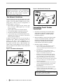
Figure 1. Attachment Concept
VM96
Console
External
Interconnect
Module
VIEW MANAGER 96
TOUCH TRACKER CONTROLLER
• Each network link supports up to 32 devices and up
to 4 network branches.
• Devices at each end point on a network link must be
terminated. Each network link supports up to 4
terminated devices.
• The VM96 console provides 4 SensorNet links.
SensorNet J-Boxes provide additional links.
• Each Touch Tracker controller attaches to the
network via an External Interconnect Module
(EIM), which provides the controller with power
and network termination.
See the Backbone and Star Network Guidelines on
the following page to determine the appropriate network
configuration for the controllers on your system.
Backbone Network Guidelines
The backbone network topology uses a single cable that
passes through each EIM, as shown in Figures 2 and 3.
In Figure 2, the EIMs at each end of the backbone must
be terminated. All other interconnect points, including
the console, are unterminated. In Figure 3, the console
and the last EIM are terminated. All other interconnect
points are unterminated.
Figure 2. Backbone Network Example #1
T - Terminated
VM96
Console
Power Supply
SensorNet
SensorNet Cable
Cable
T
T
EIMs
EIMs
Touch Tracker Controllers
Touch
Tracker
Figure 3. Backbone Network Example #2
T - Terminated
VM96
Console
T
Planning the Touch Tracker
Network
The VM96 system supports a maximum of 8 Touch
Tracker controllers (controller). Controllers can attach
in a variety of configurations, but must follow all
SensorNet configuration and termination rules.
SensorNet Cable
T
EIMs
EIMs
Touch Tracker Controllers
• A network link's maximum length is 1350m (4430').
8000-0748-01, Rev. C
SENSORVISION SYSTEMS
1
Daisy chain wiring, which uses separate cable
segments between devices, is not recommended for
attaching Touch Trackers. Any break in the chain
could make all Touch Trackers inoperable or
inaccessible from the VM96 system.
Figure 5. Star Network Example #2
T - Terminated
VM96
Console
T
Star Network Guidelines
• Each network link supports one star network, with
up to 32 devices. VM96 supports up to 8 Touch
Tracker controllers.
• Only one hub is allowed for each star network.
• A network hub supports a maximum of four legs.
• The device at the hub is always unterminated.
• A star network leg can attach unterminated daisychained devices; however, the device at the end of
each leg must be terminated.
In Figure 4 the EIMs at the end of each leg must be
terminated; other EIMs are unterminated. Since the
console is the hub in this configuration, it is
unterminated. In Figure 5, the second EIM attached to
the console is the hub, and it is not terminated. The
VM96 console, and the EIMs at the end of each leg;
must be terminated. Other EIMs are daisy-chained and
unterminated.
T
1. Review the network design to determine which
Touch Tracker controllers (controller) must be
terminated. Set jumper E1 on EIMs requiring
termination (Figure 6).
2. Mount each EIM on a wall or other surface within
3m (10') of its attached controller. Then route a
twisted-pair SensorNet cable from the VM96
console, past each EIM, until the last EIM is
reached. Do not cut the cable at each EIM.
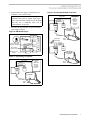
3. Referring to Figures 6 through 8:
a.
VM96
Console
c.
Hub
SensorNet
Cable
T
T
EIMs
T
Connecting Touch Tracker
Controllers
b.
T - Terminated
EIMs
Touch Tracker Controllers
Figure 4. Star Network Example #1
EIMs
T
EIMs
The star network topology has legs running from a hub
(central connection) to the attached EIMs. The console,
a J-Box, or one of the domes or EIMs can serve as the
wiring point or "hub" for the star configurations, as
shown in Figures 3-17 and 3-18.
T
SensorNet
Cable
Hub
d.
T
e.
Touch Tracker Controllers
f.
Wire each EIM’s power supply leads to pins 2, 3,
and 4 of a 5-pin compression connector (one
connector per EIM). Tighten the fastening screws to
secure the wires.
Strip 25mm (1") of outer insulation from the
SensorNet cable at each EIM location. Then strip
12mm (.5") of insulation from each wire.
Bend the two wires in the middle of the stripped
area. Insert one wire into pin 1, and the other into
pin 5 of the EIM's 5-pin compression connector.
Tighten both fastening screws to secure the wires.
After attaching power and SensorNet cables, plug the
wired 5-pin connector into each EIM's WAG005
connector. See Figure 6.
Connect the EIM SensorNet cable to the SensorNet
card or preceding SensorNet device. Then connect
the cable between the last EIM and the next
SensorNet device.
Plug the modular interconnect cable into the RJ45
connector on the back of the Touch Tracker
controller. Use the strain relief, if available. Plug the
other end into the EIM.
Touch Tracker Controllers manufactured before
late-1996 do not have a strain relief.
2
WORLD LEADER IN ELECTRONIC SECURITY
VIEW MANAGER 96
TOUCH TRACKER CONTROLLER
4. Plug the EIM power supply or transformer into a
grounded, 3-wire electrical outlet.
If the controller keypad and backlighting do not
illuminate when power is applied, repeat steps 3
and 4. Disconnect the controllers from the EIMs
after this test is completed. They will be
connected later, one at a time.
Figure 8. Connecting Multiple Controllers
SensorNet A
SensorNet B
24Vac A
Ground
24Vac B
SensorNet
Link:
VM96 card,
3
J-Box link,
4
or other
P1 SensorNet
device
1
2
54 321
Power
Supply
J3
5. Proceed to the next section to set up the controller
under VM96 Version 4.
J2
Touch Tracker
Controller
Figure 6. EIM Board Layout
Terminated
RJ45 Cable
J3
E1
2-3 UNTERMINATED
3 2 1
3 2 1
Power & SensorNet
Connector WAG005
J2
J1
24Vac A
Ground
24Vac B
J3
Touch Tracker
connector RJ45
Strain
Relief
SensorNet A
SensorNet B
ASSY
0301-0340-01 REV-
1-2 TERMINATED
54 321
Power
Supply
J2
RS232 connector
DB9(F)
Touch Tracker
Controller
Figure 7. Connecting 1 Controller
RJ45 Cable
SensorNet A
SensorNet B
24Vac A
Ground
24Vac B
54 32 1
J3
SensorNet
1
Link:
2
VM96 card,
3
J-Box link,
4
or other
P1 SensorNet
device
Power
Supply
Strain
Relief
J2
Touch Tracker
Controller
J2
RJ45 Cable
Strain
Relief
SENSORVISION SYSTEMS
3
Installing Touch Trackers
Under VM96 Version 4
This section is organized as follows:
• Installing new Touch Trackers under VM96 v4.
• Upgrading Touch Trackers Installed under a Prior
Version of VM96.
• Placing a v4 Touch Tracker into local mode.
With VM96 v4, camera domes attaching via SensorNet
will use SensorNet addresses 1-96. To avoid addressing
conflicts, Touch Tracker controllers which previously
used SensorNet addresses 1-8 will use addresses 254247, respectively. The LCD display continues to show
address 1-8.
The next section discusses installing new Touch
Trackers under VM96 v4.
Installing New Touch Trackers Under
VM96 v4
Use this procedure when attaching new Touch
Tracker controllers for the first time.
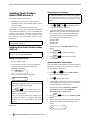
Calibrating the Tracker Ball
No calibration values are saved unless you complete
entire calibration sequence. If you exit prematurely,
the Touch Tracker controller will retain its prior
settings.
0
9
1. Press
, Menu , and
on the Touch Tracker
to begin the calibration operation.
2. The following instructions will appear on the LCD
display, one line at a time. Press the tracker ball as
far as it will go in the stated direction and hold it
until the next message appears. Release the ball
before moving it to the next position.
Press
Press
Press
Press
Ball
Ball
Ball
Ball
Right
Left
Down
Up
3. Release the ball when the Release Ball message
appears.
Clear
4. Press Entry
to finish the calibration.
Clear
Attach One Touch Tracker
5. Press Entry
Control mode.
1. Start the VM96 console.
Attaching Another Touch Tracker
2. Attach the first controller. After going through its
startup sequence, the controller displays the
following LCD message:
You must assign each controller to a different address.
Otherwise, you will see an *, followed by a number in
the LCD display's address area.
Sensormatic
Touch Tracker v4
0
3. After a few moments, the LCD displays:
Cam
Mon
A1
__
The controller may cycle several times with an r
in the upper right-hand section of the LCD. An A
indicates the address was accepted.
Clear
Entry
Press
if the controller stalls with a
TTR message at the bottom of the LCD screen or
if there is no text visible.
If you see *1 in the address area, another device
is assigned to address 1. Assign the previouslyinstalled device to another address and repeat
steps 1-3.
Continue with the following section to calibrate the
tracker ball.
4
again to return to Camera
WORLD LEADER IN ELECTRONIC SECURITY
, then Menu to select Utility Mode on
1. Press
the Touch Tracker just installed.
2. Press
2
to set the link address.
3. Enter an address other than 1. This frees up address
1 for installing the next controller. Be sure to assign
a different address to each controller.
4. The controller displays Checking Address
Availability. If accepted, Address
Granted/Press Clear appears.
Clear
5. Press Entry
Mode.
twice, to go to Camera Control
6. The controller displays the following LCD message
(# is the new address–near the right edge of the
screen):
Cam
Mon
A#
__
VIEW MANAGER 96
TOUCH TRACKER CONTROLLER
7. Attach another Touch Tracker controller. After
startup, the controller displays the following LCD
message (address near the center of the screen).
Cam
Mon
A1
__
Downloading the Touch Tracker
1. From the VM96 Administrator menu, press Alt+U
to select the Utilities pull-down menu. Then select
Network Maintenance. A device selection dialog
box appears.
8. Continue with Calibrating the Tracker Ball, on
the preceding page.
2. Move the cursor to select Touch Tracker 3.0 and
press ENTER.
Upgrading Touch Trackers Installed
under a Prior Version
3. Type a Touch Tracker's previously-assigned device
number (1-8) into the device number field and press
ENTER. The system responds with a message that
it does not recognize the device. It then selects the
Force Download EE function.
Use this procedure to upgrade Touch Tracker
controllers installed under VM96 v3 to a v4
system. You may do this because you want to use the
I/O Module or SensorNet domes, which were not
supported on earlier versions.
To avoid addressing conflicts, connect SensorNet
domes after upgrading Touch Tracker controllers.
Work with one Touch Tracker at a time.
Checking the Touch Tracker Version
Before performing the upgrade, you must first
determine which Touch Tracker version you are using.
Older Touch Trackers require downloading. Newer
Touch Trackers are capable of operating in version 3 or
version 4 mode.
1. Plug in the Touch Tracker without the VM96
console powered up.
2. Determine if Touch Tracker starts in remote mode.
The Touch Tracker is in remote mode if it looks like
the following:
Cam
Mon
r#
__
Continue with Setting Up Version 4.x Touch
Trackers.
If the Touch Tracker does not start in remote mode,
continue with Downloading the Touch Tracker.
The version of the Touch Tracker may also be
determined by selecting option 5 from the VM96
Utility menu.
If the version number is 0701-0030-0403, continue
with Setting Up Version 4.x Touch Trackers.
If the version number is 0701-0030-0315 or 07010030-0317, continue with Downloading the Touch
Tracker.
4. Press Alt+P and then R to begin the download.
The Touch Tracker resets following the download.
The operation is complete when you see the
following LCD message (# is the new address–near
the right edge of the screen):
Cam
Mon
A#
__
The controller may cycle several times with an r
in the upper right-hand section of the LCD. An A
indicates the address was accepted.
Clear
Press Entry
if the controller stalls with a
TTR message at the bottom of the LCD screen.
5. Calibrate the tracker ball, following the procedures
on the preceding page.
6. Repeat steps 1-5 for all attached Touch Tracker
controllers.
Setting Up Version 4.x Touch Trackers
1. Hold down the 4 button on the Touch Tracker prior
to plugging in the unit.
2. Plug in the RJ-45 connection on the back of the
Touch Tracker while continuing to press the 4
button.
3. Continue to hold the 4 button while the unit goes
through its power-up sequence.
4. The Touch Tracker momentarily displays:
Sensormatic
Touch Tracker v3
Then all lights flash on the Touch Tracker, and the
LCD displays:
Sensormatic
Touch Tracker v4
Continue with Calibrating the Tracker Ball on page 4.
SENSORVISION SYSTEMS
5
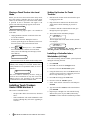
Placing a Touch Tracker into Local
Mode
Setting Up Version 3.x Touch
Trackers
Before you can access the Touch Tracker utility menu,
the Touch Tracker controller must be in local mode.
Under v4, the controller goes into remote mode when it
is powered on and a SensorNet scan signal is not
present. The following message appears on the LCD:
1. Hold down the 3 button on the Touch Tracker prior
to plugging in the unit.
Cam
Mon
r#
__
Perform the following steps to place a v4 controller in
local mode:
1. Unplug the RJ45 connector on the back of the unit
to reset the controller.
2. Re-attach the connector. During the first five
seconds, repeatedly press the A button (to the left of
the LCD screen), until you hear the unit click.
Clear
3. Press Entry
when you see ---X-->TTR on
the LCD screen. The controller is in local mode
when you see the following LCD message (# is the
unit's address):
Cam
Mon
*#
__
You can now access the Touch Tracker utility menu.
If you see the following message (# is the device
address), after startup of a v4 Touch Tracker that is
locally-attached to an operational VM96, an error is
indicated.
Cam
Mon
r#
__
The error could be caused by incorrect wiring or
incorrect device termination. It may also occur if the
VM96 system is not operating or the SensorNet
Communications Controller board has failed.
Installing Touch Trackers
Under VM96 Version 3
This section is included because:
− The procedure differs from Version 4, discussed
above.
− Some installations will install additional Touch
Trackers, although they will not be upgrading to
Version 4.
6
WORLD LEADER IN ELECTRONIC SECURITY
2. Plug in the RJ-45 connection on the back of the
Touch Tracker while continuing to press the 3
button.
3. Continue to hold the 3 button while the unit goes
through its power-up sequence.
4. The Touch Tracker momentarily displays:
Sensormatic
Touch Tracker v4
Then all lights flash on the Touch Tracker, and the
LCD displays:
Sensormatic
Touch Tracker v3
Continue with Calibrating the Tracker Ball and
Attaching Another Touch Tracker on page 4.
Installing a Controller into a
Workstation (v3 Only)
You will be working with the VM96 system keyboard
during the following activities.
1. Press ENTER.
2. Press Alt+c to invoke the Configure menu.
3. Press w to select the Workstations option.
4. Using the down arrow, move to the Device field. If
you have at least one device configured, proceed to
the next step. Otherwise, go to step 7.
5. Press Alt+f to bring up the Form menu.
6. Press a to select the Add Row option.
7. Select Touch Tracker at the Device field and press
ENTER.
8. Type the controller's address at the Num field and
press ENTER.
9. Repeat steps 5 through 8 for each controller being
added to the system, or press Alt+x, followed by
ENTER to exit the controller installation procedure.
VIEW MANAGER 96
TOUCH TRACKER CONTROLLER
Using the VM96 and Touch
Tracker Controller Utilities
See Chapter 21 of the VM96 System Administrators
Manual (8000-0756-04) for guidance on using the
VM96 Utilities.
See Chapter 6 of the VM96 Operators Manual (80000848-04) for guidance on using the Touch Tracker
Utilities.
Installing a Remote Touch
Tracker
VM96 supports communication with a remotely-located
Touch Tracker using RS232 communications. A local
Touch Tracker must be dedicated while the remote unit
is in use. The two Touch Trackers connect through the
RS232 ports on their respective EIMs. Using modems
allows the distance to be extended, and supports
communications over voice-grade leased or switched
lines.
When attaching with a modem, use a conventional
modem cable and DB25 to DB9 converter, if required.
Wire
1
2
3
EIM #1
Pin 2-Tx ............
Pin 3-Rx............
Ground..............
EIM #2
Pin 3-Rx
Pin 2-Tx
Ground
SENSORVISION SYSTEMS
7