1
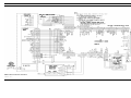
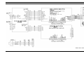
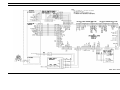
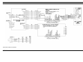
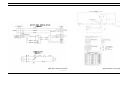
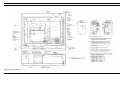
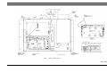
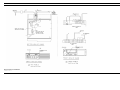
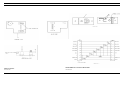
LBI-39011B Maintenance Manual MDX And ORION WALL MOUNT STATION TABLE OF CONTENTS Interconnect Board . . . . . . . . . . . . . . . . LBI-39046 LBI-39052 Keypad/Frequency Select Board . . . . . . . . . LBI-39047 LBI-39195 Remote Interface Board . . . . . . . . . . . . . LBI-39048 ericssonz Ericsson Inc. Private Radio Systems Mountain View Road Lynchburg, Virginia 24502 1-800-528-7711 (Outside USA, 804-528-7711) Printed in U.S.A. LBI-39011B SYSTEM SPECIFICATIONS* TABLE OF CONTENTS SYSTEM SPECIFICATIONS . . . . . . . . . DESCRIPTION . . . . . . . . . . . . . . . . MECHANICAL PACKAGE . . . . . . RADIO PACKAGE . . . . . . . . . . . TONE AND EDACS REMOTE . . . . . POWER SUPPLY . . . . . . . . . . . . CONTROL PANEL . . . . . . . . . . . PROGRAMMING . . . . . . . . . . . . BATTERY STANDBY OPTION . . . . OPERATION . . . . . . . . . . . . . . MAINTENANCE . . . . . . . . . . . . . . . PREVENTIVE MAINTENANCE . . . ASSEMBLY AND DISASSEMBLY . . OPTION INSTALLATION INSTRUCTIONS INITIAL ADJUSTMENT AND CHECKOUT STATION ADJUSTMENT PROCEDURES . INTERCONNECTION DIAGRAMS . . . . . ASSEMBLY DIAGRAMS . . . . . . . . . . MECHANICAL LAYOUT . . . . . . . . . . OUTLINE DIAGRAM . . . . . . . . . . . . PARTS LIST . . . . . . . . . . . . . . . . . . . . . . . . . . . . . . . . . . . . . . . . . . . . . . . . . . . . . . . . . . . . . . . . . . . . . . . . . . . . . . . . . . . . . . . . . . . . . . . . . . . . . . . . . . . . . . . . . . . . . . . . . . . . . . . . . . . . . . . . . . . . . . . . . . . . . . . . . . . . . . . . . . . . . . . . . . . . . . . . . . . . . . . . . . . . . . . . . . . . . . . . . . . . . . . . . . . . . . . . . . . . . . . . . . . . . . . . . . . . . . . . . . . . . . . . . . . . . . . . . . . . . . . . . . . . . . . . . . . . . . . . . . . . . . . . . . . . . . . . . . . . . . . . . . . . . . . . . . . . . . . . . . . . . . . . . . . . . . . . . . . . . . . . . . . . . . . . . . . . . . . . . . . . . . . . . . . . . . . . . . . . . . . . . . . . . . . . . . . . . . . . . . . . . . . . . . . . . . . . . . . . . . . . . . . . . . . . . . . . . . . . . . . . . . . . . . . . . . . . . . . . . . . . . . . . . . . . . . . . . . . . . . . . . . . . . . . . . . . . . . . . . . . . . . . . . . . . . . . . . . . . . . . . . . . . . . . . . . . . . . . . . . . . . . . . . . . . . . . . . . . . . . . . . . . . . . . . . . . . . . . . . . . . . . . . . . . . . . . . . . . . . . . . . . . . . . . . . . . . . . . . . . . . . . . . . . . . . . . . . . . . . . . . . . . . . . . . . . . . . . . . . . . . . . . . . . . . . . . . . . . . . . . . . . . . . . . . . . . . . . . . . . . . . . . . . . . . . . . . . . . . . . . . . . . . . . . . . . . . . . . . . . . . . . . . . . . . . . . . . . . . . . . . . . . . . . . . . . . . . . . . . . . . . . . . . . . . . . . . . . . . . . . . . . . . . . . . . . . . Page 1 1 1 1 2 2 2 2 2 2 3 3 3 3 3 3 4 10 13 14 15 NOTICE! FREQUENCY RANGE (Refer to Mobile Radio Specification) INPUT VOLTAGE 90-130 VAC @ 50-65 Hz 180-260 VAC @ 50-65 Hz INPUT POWER Standby Receive Transmit 60 Watts 100 Watts 500 Watts POWER OUTPUT RATINGS (Refer to Mobile Radio Specification) DUTY CYCLE (EIA) Receiver 100%, Transmitter 20% TEMPERATURE RANGE -30°C to +60°C (-22°F to +140°F) (Performance specified per EIA) SPEAKER 4 ohms DIMENSIONS (HxWxD) 54 x 57.2 x 17.5 cm. (21 x 22 x 6 inches) WEIGHT 66 pounds with MDX Radio 58 pounds with ORION radio *For detailed transmitter and receiver specifications, refer to the appropriate mobile Maintenance Manual. DESCRIPTION The Wall Mount Station Combination utilizes state-ofthe-art microcomputer technology for high value and reliability. The most advanced manufacturing techniques are used to provide the highest quality radio possible. This manual covers Ericsson and General Electric products manufactured and sold by Ericsson Inc. The Tone Remote conventional station provides four (4) frequency and the EDACS system provides five (5) frequency operation. NOTICE! Repairs to this equipment should be made only by an authorized service technician or facility designated by the supplier. Any repairs, alterations or substitution of recommended parts made by the user to this equipment not approved by the manufacturer could void the user’s authority to operate the equipment in addition to the manufacturer’s warranty. The software contained in this device is copyrighted by the Ericsson Inc. Unpublished rights are reserved under the copyright laws of the United States. This manual is published by Ericsson Inc., without any warranty. Improvements and changes to this manual necessitated by typographical errors, inaccuracies of current information, or improvements to programs and/or equipment, may be made by Ericsson Inc., at any time and without notice. Such changes will be incorporated into new editions of this manual. No part of this manual may be reproduced or transmitted in any form or by any means, electronic or mechanical, including photocopying and recording, for any purpose, without the express written permission of Ericsson Inc. The station radio combination can be equipped with: • RF Channel Synthesizer The Wall Mount Station is available in: • All frequency bands and power levels of MDX • All frequency bands of the Orion low power package • All frequency bands of the Orion mid power package The Wall Mount Station is not available in: NOTICE! Board and Power Supply. The Interconnect Board has the Interface (19D902931G1) Board with the station three (3) watt audio stage on it. The Keypad Frequency Select Board is mounted on the Interconnect Board. The power on-off switch (circuit breaker) is located on the Power Supply. The radio has its own power on-off switch. A System Interconnect cable connects the Interconnect board, Remote board and Power Supply with the radio. • All frequency bands of the Orion high power package • Low Band Orions It operates from 120 or 240 VAC power supplies at frequencies of 50 or 60 Hz. Input power variations of ± 20% are tolerated. MECHANICAL PACKAGE The station is housed in a slim (less than 7 inches) and compactly built cabinet, occupying a minimum of space. It consists of a Mobile Radio, Remote Board, Interconnect • Microcomputer Control System • Two Channel Tx/Rx • ±0.0002% or ±0.0005% stability • Ultra High Sensitivity Preamp • Tone or Digital Channel Guard • Microphone RADIO PACKAGE The Mobile Radio is a synthesized, wideband radio that uses integrated circuits and microcomputer technology to provide high performance trunked operation. The radio operates in the Enhanced Digital Access Communications System (EDACS) trunking environment and/or conventional communications systems. Copyright© January 1994, Ericsson GE Mobile Communications Inc. 1 LBI-39011B All radio functions are stored in a programmable Electrically Erasable PROM (EEPROM). The radio is field programmable using an IBM compatible personal computer with the following equipment. • Serial Programming Interface Module TQ3370 • Programming Cable (19B801417P10) TQ3372 With correct cable and software, any PC can be used to program (or re-program) customer system frequencies, Channel Guard Tones, and options. Option selection is done during radio initialization using the PC programmer. * For Mobile information see appropriate Mobile LBI. TONE AND EDACS REMOTE The EDACS remote boards provide the electrical interface between the Local Controller and the Base Station. They generate the required tones for selecting remotely controlled functions. Refer to the Maintenance Manual for the individual remote board for detailed information. The manuals for these boards are: • Four Frequency Tone Remote 19A704686P6 . . . . . . . . . . . . . . . . LBI-31552 • EDACS Five Function Tone Remote 19A704686P8 . . . . . . . . . . . . . . . . LBI-38119 POWER SUPPLY The Power Supply is a self-contained module that provides a single output of 13.8 VDC. Refer to the Power Supply Maintenance Manual LBI-38751 for detailed information on the 13A Supply and LBI-38893 on the 30 Amp supply. CONTROL PANEL Both the Power Supply and Radio have power ON-OFF switches. Operating controls located on the station control panel on the System board are: (1) the REMOTE On-Off switch, (2) the INTERCOM On-Off-Mom switch, (3) the SPEAKER On-Off switch, (4) VOLUME control, (5) Power LED, and (6) Microphone connection. REMOTE Permits the serviceman to communicate through, or monitor, the operating channels. INTERCOM Provides Intercom capability between the station and remote controller when ON. Intercom is disabled when OFF. Provides momentary connection for Intercom calls in the MOM position. SPEAKER Connects the speaker to the receiver audio from the radio. VOLUME Adjusts the station audio level. 2 PROGRAMMING The radio in the Wall Mount Station is programmed by an IBM compatible personal computer equipped with a serial port. The Wall Mount Station connects to the computer with a MDX TQ3372 programming cable through a TQ3370 Interface Box. The TQ3370 Interface provides the RS232 to TTL level conversion needed by the radio and the 12V Vpp voltage needed to program some radios. IMPORTANT: The MDX programming cable connects to the Wall Mount Station’s mic connector. It does NOT connect to the radio’s mic connector. The computer must run the programming software appropriate to the radio inside the Wall Mount Station. After programming the station, power must be turned OFF and then back ON. This is to reset the radio and if installed, the keypad frequency select board. Note the keypad frequency select board is disable during programming and must be reset before it resumes communicating with the radio. MDX PROGRAMMING CONSIDERATIONS: The MDX radio will operate in the Wall Mount Station with all versions of radio flash software. Wall mount operation has a minimal effect on radio personality. The main difference between a Wall Mount Station personality and a Mobile personality is the ability to add four channels if used with a conventional tone remote board or five system/group combinations if used in an EDACS environment with an EDACS tone remote board. For multi-frequency operation, • OUT1 must be programmed as a "RX Mute" line with a sense of "High". • INP2 must be programmed as a "Disabled". • Up to four channels may be defined in the system/group key menu for a conventional only radio or up to five system/group combinations may be defined in an EDACS radio. • A radio "keyboard" must be defined and loaded which has the desired number of remote channel or system/group combinations. BATTERY STANDBY OPTION A battery standby option is available to permit continued station operation in the event of an AC power failure. The option provides internal switching in the station to a customersupplied 13.8VDC battery supply. NOTE The battery standby option does not charge the standby batteries. The standby battery option consists of a relay (K1) mounted on the station chassis, with a cable that interconnects the station power supply, the station power cable, and the external power supply. When the station is powered by an AC voltage, relay K1 of the battery standby option is energized and the station receives DC power from the internal power supply. If the AC line power fails, relay K1 is no longer energized, and DC power is supplied from the back-up battery. When the AC power returns, K1 reenergizes and DC power is again supplied from the internal power supply. OPERATION ORION PROGRAMMING CONSIDERATIONS: The ORION radio requires Group 22 or later radio flash software to operate properly in the Wall Mount/Desktop station. Further, its personality must be programmed with EDACS 3 Version 12 or later. Earlier versions of software may not recognise a keyboard/frequency select board and may not operate the RX mute line. The station ON-OFF switch is located on the power supply. When this ON-OFF switch is ON, all controls on the radio should be active except for the volume control. NOTE Before leaving the station make sure the REMOTE switch is ON and all other switches are OFF. Monitoring a Channel The personality also depends on wether the Wall Mount Station is set for single frequency remote or a multi-frequency remote operation. For single frequency operation, • OUT1 must be programmed as a "RX Mute" line with a sense of "High". • INP2 must be programmed as a "PTT" input. 1. Set the power supply ON-OFF switch to ON. 2. Set the radio power ON-OFF switch to ON. 3. Set the SPKR switch to ON. 4. Select the desired channel. 5. Adjust the VOLUME control to a comfortable listening level. 6. When monitoring is complete return the REMOTE switch to ON and all other switches to the OFF position. Intercom To Local Controller 1. Set the power supply ON-OFF switch to ON. 2. Set the radio power ON-OFF switch to ON. 3. Plug microphone into mic jack J1 on left side of the control panel. 4. Set SPKR switch to ON. 5. Set INTERCOM switch to ON. 6. When receiving, set VOLUME control for comfortable listening level. 7. When communications are completed return the REMOTE switch to ON and all other switches to the OFF position. Radio Communications To Receive A Message 1. Set the power supply ON-OFF switch to ON. 2. The microphone PTT switch keys the transmitter on the channel indicated. If more than one frequency is available, select the desired frequency using the radio frequency selector. 3. Set the SPKR switch to ON. 4. The station is now ready to receive messages from other radios in the system. When the first call is received, it may be necessary to adjust the VOLUME control for the desired listening level. To Transmit A Message 1. If more than one channel is available, select the proper channel using the radio frequency selector. 2. Monitor the channel to make sure no one else is using the channel. 3. Press the PTT switch on the microphone. Then speak into the microphone using a normal speaking voice. Always release the PTT switch as soon as the message is completed, and listen for an answer to the call. LBI-39011B MAINTENANCE PREVENTIVE MAINTENANCE To ensure high operating efficiency and to prevent mechanical and electrical failures from interrupting system operations, routine checks should be made of all mechanical and electrical parts at regular intervals. This preventive maintenance should include the checks as listed in the table of Maintenance Checks that follows. ASSEMBLY AND DISASSEMBLY Easy access to the station is inherent in this design. Simply unlock the door and swing it open. The station and radio package are hinged so that they can swing out for servicing. To release the entire station and allow it to swing out, remove the three screws on the left that secure the chassis to the cabinet brace. Then press the spring clip. Loosening the right side radio mounting screws allows the radio package to hinge open, providing access to the Remote Board, Interconnect Board, and Option Boards. Remote Board To remove the Remote Board, remove the POZIDRIVOR screw in the four corners of the board and remove the board. Unplug cabling as necessary. Interconnect Board To remove the Interconnect Board, remove the four screws securing it to the chassis and disconnect all cabling. Remove the Interface Board and/or the Keypad Board if necessary. OPTION INSTALLATION INSTRUCTIONS Most options are radio options, and are thus the same in both installation and operation when the radio is used in the Wall Mount application. Refer to the applicable Maintenance Manual for mobile radio options. INITIAL ADJUSTMENT AND CHECKOUT After the station has been installed as described in the Installation Manual, the following adjustments should be made by an authorized electronics technician. TEST EQUIPMENT REQUIRED 1. Deviation Monitor INTERVAL BETWEEN CHECKS Every Six Months As Required Transmitter Alignment - Compare meter readings with voltages read during initial tune up. Check power output. (See Alignment Procedure for Transmitter.) X Receiver - Retune the front end and check meter readings taken during initial tune-up. (See Alignment Procedure for Receiver.) X 2. Wattmeter, 50 ohms, 150 Watts 3. RF Generator, (Station RF Frequencies) 4. AC Voltmeter 5. 30 dB Decoupler TRANSMITTER ADJUSTMENT The adjustment for the transmitter includes measuring the forward and reflected power, adjusting the antenna length for optimum ratio, and then setting the transmitter to rated power output. Next, measure and record the frequency and modulation for future reference. For complete transmitter adjustment, refer to the Alignment Procedure in the applicable radio unit Maintenance Manual. RECEIVER ADJUSTMENT Initial adjustment for the receiver includes adjusting the audio output power for 3 watts across the speaker. Refer to the Maintenance Manual for the radio being used for Troubleshooting and Alignment Procedures, or Adjustments. STATION ADJUSTMENT PROCEDURES Your station was adjusted at the factory. If adjustment is needed due to board replacement, or other reasons, perform the following steps. REMOTE SETUP BATTERY STANDBY OPTION Receiver to Line An external battery can be used to power the station in the event of AC power failure. The battery and charger must be supplied by the customer. The standby option consists of Option Cable Assembly 19B802942. Refer to the Battery Standby Option Application Assembly for installation. NOTE 1. Turn ON Power and Speaker switches. The battery standby option does not recharge the battery. TABLE OF MAINTENANCE CHECKS 2. Set REMOTE and INTERCOM switches to OFF. 3. Connect the RF Generator to the station. Set the proper RF frequency and a 1 kHz tone at 3 kHz deviation. 4. Connect the proper RCN1000 Remote Controller to J11 on the rear of the station chassis. 5. No tone should be present at the Remote Controller. Transmission Line - Check for positive indication of pressure on transmission line pressure gauge (if pressurized line is used). X Antenna - Check antenna and mast for mechanical stability. X Mechanical Inspection - Visually check cables, plugs, sockets, terminal boards, and components for good electrical connection. Check for tightness of nuts, bolts, and screws to make sure that nothing is working loose from its mounting. X Cleaning - Use a vacuum cleaner to remove accumulated dust inside the cabinet. X Frequency Check - Check transmitter frequency and deviation as required. X 6. Turn on the REMOTE switch. A tone should be present at the Remote Controller. a. On the (931) Interface Board, set R323 for 0 dBm at J1-3 and J1-4 on the (686P6) Tone Remote Board.. a. On the Tone Remote Board (19A704686P6) set R35 for 0 dBm at J1-3 and J1-4. b. On the (931) Interface Board, set R323 for 0 dBm at TB1-2 and TB1-5 on the (686P8) PST Remote Board. b. On the EDACS Tone Remote Board (19A704686P8) set R66 for 0 dBm at TB1-2 and TB1-5. Line to TX 7. Turn OFF the station REMOTE switch. Disconnect the RF Generator and connect the wattmeter to the station through the 30 dB decoupler. 1. Set Station Remote switch and InterCom switch to OFF. 8. Apply a 30 mVRMS 1 kHz tone across J101-1 Desk Mic Hi and J101-2 Desk Mic Lo. 3. On the Controller, press SF5 on EDACS only, and ground PTT. Check to see that the Radio is not keyed. 9. Ground J101-3 Desk Mic PTT. Measure the RF power on the wattmeter. 4. Switch the Station Remote switch ON. Key the Controller. Check to see that the radio is keyed. 10. With J101-3 grounded, check for 20 to 43 mVRMS, 1 kHz tone across J209-5 (Mic Hi) and J209-7 (Mic Lo). Check to verify that no tone is present at the Remote Controller. Remove the ground. (An isolation transformer may be required.) 5. The Controller should be preset to 0 dBm. 11. Switch the INTERCOM switch ON. Ground J101-3 Desk Mic PTT. Check to verify that the radio does not key (no power on the wattmeter). Check to verify that a tone is present at the Remote Controller. Press the INTERCOM switch to the MOM position and check for a tone at the Remote Controller. Release the INTERCOM switch. 2. Apply 1 kHz at 120 mV to Microphone input of the Controller. a. On the 686P6 PST Remote Board, set R60 for 60 mVRMS at J209-5 and J209-7. b. On the 686P8 PST Remote Board, set R82 for 60 mVRMS at J209-5 and J209-7. 6. Before leaving the station, make sure the INTERCOM and SPEAKER switches are OFF, and the REMOTE switch is ON. 3 LBI-39011B ORION WALL MOUNT STATION (188D5407, Sh. 1, Rev. 3) 4 INTERCONNECTION DIAGRAM INTERCONNECTION DIAGRAM LBI-39011B ORION WALL MOUNT STATION (188D5407, Sh. 2, Rev. 3) 5 LBI-39011B ORION WALL MOUNT STATION (188D5407, Sh. 3, Rev. 3) 6 INTERCONNECTION DIAGRAM INTERCONNECTION DIAGRAM LBI-39011B MDX WALL MOUNT STATION (19D904992, Sh. 1, Rev. 1) 7 LBI-39011B MDX WALL MOUNT STATION (19D904992, Sh. 2, Rev. 1) 8 INTERCONNECTION DIAGRAM INTERCONNECTION DIAGRAM LBI-39011B MDX WALL MOUNT STATION [Optional] Battery Back-Up Relay Assembly (19D904992, Sh. 3, Rev. 1) (19B802942, Shts. 1&2, Rev. 0) 9 LBI-39011B WALL MOUNT STATION (19D904975, Sh. 1, Rev. 3) 10 ASSEMBLY DIAGRAM ASSEMBLY DIAGRAM LBI-39011B WALL MOUNT STATION (19D904975, Sh. 2, Rev. 3) 11 LBI-39011B WALL MOUNT STATION (19D904975, Sh. 3, Rev. 3) 12 ASSEMBLY DIAGRAM MECHANICAL LAYOUT LBI-39011B CONTROL PANEL FAN THERMOSTAT ASSEMBLY (19D904974, Sh. 1, Rev. 1) (19B801127, Sh. 1, Rev. 2) 13 LBI-39011B OUTLINE DIAGRAM (19C852376, Rev. 1) (19B802699, Rev. 1) SWITCH PANEL 19C852424G1 14 MICROPHONE CONNECTOR BOARD 19C852376G1 PARTS LIST WALL MOUNT STATION SYMBOL PART NO. DESCRIPTION LBI-39011B SYMBOL PART NO. - - - - - - - - INDICATING DEVICES - - - - - - - SYMBOL PART NO. DESCRIPTION WM STATION CABINET 19D402658G2 J501 19B209343P1 - - - - - - - - - - - JACKS - - - - - - - - - - Connector, Receptacle. DS1 19A134354P1 19A122184P1 Grill. 4 19B205311P1 Angle. 6 7 5491682P14 N130P1410B6 Rim lock. Thread forming hex head screw. 8 19D402658P8 Cabinet Assembly. 9 10 19A122059P4 N130P2416B6 Pad. Thread forming hex head screw. 11 N402P71B6 Plain wide steel washer. 13 15 19B205409P1 4035267P1 Latch Spring. Drive rivet. 17 18 N402AP38B6 Plain steel washer. 19B201074P306 Tap screw, Phillips POZIDRIV: No. 6-32 x 3/8. 21 22 7763541P6 19A701863P19 Retaining Strap. Loop clamp: sim to Weckesser 3/8-6. - - - - - - - MISCELLANEOUS - - - - - - - - - - - - - - - - - - LOUDSPEAKERS - - - - - - - - LS1 344A3269P1 S3 19A700189P11 Toggle Switch. Magnet, Loudspeaker, Permanent. W4 19B801729P2 Microphone cable. W5 W6 344A3337P3 19B801735P2 Cable. Cable. - - - - - - - - - - - SWITCHES - - - - - - - - - - - - - - - - - - - - - CABLES - - - - - - - - - - - - - - - - - - - MISCELLANEOUS - - - - - - - - 3 4 5 6 19D904979P1 19A116677P1 19A134939P4 19A700034P5 Bracket. Bushing: sim to Hewlett-Packard No. 5082-4707. Knob. Hex nut: No. M3.5 x 0.6. 7 19A700033P6 Lockwasher, external tooth, M3.5. 8 9 10 19A700034P4 19A700032P5 7150186P3 Nut, hex: No. M3 x 0.5MM. Lockwasher, internal tooth: No. 3MM. Spacer: approx 1/8 x 1/8 inches dia. FAN/THERMOSTAT 19B801127G1 - - - - ASSOCIATED ASSEMBLIES - - - 5 19 19B205318G1 19B227009G2 19D904973P1 19C852458P1 Hinge support. Cabinet. Chassis. Right Radio Bracket. 19C852459P1 Left Radio Bracket. F1 - - - - - - - - - - - FUSES - - - - - - - - - 19A701881P18 Fuse, Cartridge, Quick Blow, .500A, 250V. S1 5496655P1 W1 19A134567P1 - - - - - - - - - - - CABLES - - - - - - - - - Power, 3 wire, 13 amps at 125 VAC, approx. 6 ft. long. XF1 19B209005P1 - - - - - - - - - - FUSE SOCKETS - - - - - - - Fuseholder: 15 amps at 250 v; sim to Littelfuse 342012. 2 3 5 6 19B801129G1 19A702464P2 7775500P46 19A702464P4 Support Strain relief. Phenolic: 1 insulated, 1 ground terminal. Bushing, strain relief. 11 B5493477P1 12 13 14 B5493477P10 7141225P3 N80P13010B6 Fan assembly, single phase: 115 VAC, 50/60 Hz, 14 w, ccw rotation; sim to Rotron "Gold Seal Venturi Muffin Fan". Fan Grille. Hex Nut: No. 6-32. Screw, Machine, Pan Head: No. 6-32 x 5/8". 15 16 17 18 N404P13B6 N402P37B6 N80P13005B6 7141225P3 Lockwasher, internal tooth: No. 6. Flatwasher: No. 6. Machine screw, Pan Head: No. 6-32 x 5/16". Hex Nut: No. 6-32. 19 20 21 N403P13B6 N80P13004B6 19J706152P5 Lockwasher: No. 6. Screw, machine, Pan Head; No. 6-32 x 1/4". Retainer strap: sim to Panduit Corp. SST-1. - - - - - - - - - - - SWITCHES - - - - - - - - - CONTROL PANEL 19D904974G1 A1 MICROPHONE CONNECTOR BOARD 19C852376G1 J101 J102 344A4485P1 19A704852P35 4 19A702455P1 - - - - - - - - - - - JACKS - - - - - - - - - - Connector, special; sim to CONXAL E4408. PWB Connector. - - - - - - - - - MISCELLANEOUS - - - - - - - - Nut, Self-Clinching, M3 x .5: sim to Pen Cat.# KF2-M3. A2 SWITCH PANEL 19C852424G1 - - - - - - - - - - - JACKS - - - - - - - - - - Printed wire, two part: 6 contacts, sim to Molex 22-29-2061. J1 19A704852P32 R1 - - - - - - - - - - RESISTORS - - - - - - - RELUA316255/5 Potentiometer, Panel Mounting, 5K Ω. S1 S2 19A700189P11 19A700189P12 - - - - - - - - - - - SWITCHES - - - - - - - - Toggle Switch. Toggle Switch. *COMPONENTS, ADDED, DELETED OR CHANGED BY PRODUCTION CHANGES HARDWARE KIT 349A9645G1 Optoelectronic: Red; sim to HP 5082-4655. - - - - - - - - - MISCELLANEOUS - - - - - - - - 3 DESCRIPTION Thermostat, snap-action: SPST, close on temp rise, auto reset, close at 110F ±5F, open at 95F +~5F, 25 amp at 120/240 VAC; sim to Metals and Controls 20400-F17-64-F110-1.5. 1 19A702381P408 Tap screw, TORX Drive, M3-0.5 x 8. 2 3 19A700034P6 19A702364P408 Nut, Hex, M4 x .7. Machine screw: TORX Drive, M3.5 - 0.6 x 8. 4 19A700033P6 Lockwasher, external tooth, M3.5. 5 6 344A3480P1 19A705406P408 Strain Relief. Machine bolt, hexagon: M4 x 0.7. 7 19B802871P1 Cover, MIC Connector. 9 19A701312P6 Flatwasher: 1.7 - 1.85 ID. 10 19A700033P7 Lockwasher, external tooth: #4. 11 N210P16B6 Nut, Hex, #10-32. 12 13 N403P19B6 N80P21005B6 Washer, Lock, External tooth: #10. Machine screw: 1/4(.250)-20 x .312. 14 N403P25B6 Lockwasher, external tooth: 1/4(.250). 15 19A702364P510 Screw, machine, pan head, TORX DRIVE: M4. 19B801454P42 Antenna Cable 19C851585P16 344A4961P1 19B801730P1 Radio Option Cable RJ Cable Interconnect/Remote - - - - - - - - - CABLES - - - - - - - - - 19B235994P2 DSCE9G 19C852054P2 DSSU3H 19B802942P1 DSSU3H 19B801212G1 Keypad/Remote Standard Power Supply Cable/Relay Assembly Battery Cable DSCE9R 19B802554P19 19C852054P3 Cable, USA Version Power Cable - - - - - - - - - MISCELLANEOUS - - - - - - - - - 15