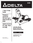
1
Owner's Manual
8-in. Wheel
314 Horsepower (continuous duty)
3450 R.P.M. (no load speed)
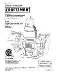
8-in. BENCH
GRINDER
Model No.
152.220180
10-in. Wheel
1 Horsepower (continuous duty)
1725 R.P.M. (no load speed)
10-in. BENCH
GRINDER
Model No.
152.220600
Customer Helpline
CAUTION:
C
us
Sears, Roebuck
Part No. OR94750
FOR YOUR OWN SAFETY; Read and follow
all of the Safety and Operating Instructions
before Operating this Bench Grinder
and Co., Hoffman
VER. 12.07
Estates,
IL 60179
1-800-897-7709
Please have your Model No.
and Serial No. available.
U.S.A.
Espafiol
pg. 19
SECTION
PAGE
Warranty ..........................................................................................................................................................................
2
Product Specifications ...................................................................................................................................................
2
Safety Instructions .........................................................................................................................................................
3
Grounding Instructions ..................................................................................................................................................
5
Specific Safety Instructions for Bench Grinders ........................................................................................................
Accessories and Attachments ......................................................................................................................................
6
6
Carton Contents ..............................................................................................................................................................
7
Know Your Bench Grinder .............................................................................................................................................
8
Assembly Instructions ...................................................................................................................................................
9
Operating the Bench Grinder ......................................................................................................................................
Maintenance ..................................................................................................................................................................
11
13
Troubleshooting G uide ................................................................................................................................................
Parts List .......................................................................................................................................................................
13
14
Espahol ..........................................................................................................................................................................
19
FULL ONE YEAR WARRANTY
If this product fails due to a defect in material or workmanship within one year from the date of purchase, return it
to the nearest Sears Service Center for repair, free of charge.
This warranty gives you specific legal rights, and you may also have other rights, which vary, from state to state.
Sears, Roebuck and Co., Dept. 817 WA, Hoffman Estates, IL 60179
8-in. Bench Grinder
Motor
Continuous duty HP
Volts
Hertz
10-in. Bench Grinder
Motor
3/4
120
60
Continuous duty HP
Volts
Hertz
1
120
6O
RPM
Grinding Wheel Size
3450 R.P.M. (no load speed)
8" diameter x 1" face x
1" bore
RPM
Grinding Wheel Size
1725 R.P.M. (no load speed)
10" diameter x 1" face x
1-1/4" bore
Grinding Wheel Grit
Shaft diameter
60, 120
5/8" diameter
Grinding Wheel Grit
Shaft diameter
60, 120
3/4" diameter
Arbor Bushing
1" diameter x 1" face by
5/8" bore
Arbor Bushing
1-1/4" diameter x 1" face by
3/4" bore
Lamp
120V, 40 watt Type A or
smaller bulb-Medium Base
(bulb not included)
Left and Right
Clear Lexan Left and Right
Left and Right
Yes
Yes
Lamp
120V, 40 watt Type A or
smaller bulb-Medium Base
(bulb not included)
Left and Right
Clear Lexan Left and Right
Left and Right
Yes
Yes
Tool Rests
Eye Shield Assemblies
Spark Arrestors
Quench tray
Wheel Dresser
Tool Rests
Eye Shield Assemblies
Spark Arrestors
Quench tray
Wheel dresser
Toavoidelectricalshockto yourselfanddamageto the
BenchGrinder,usepropercircuitprotection.
TheBenchGrinderis factorywiredfor120V,60Hz,
operation.
Connectto a 120V,15ampbranchcircuit
GENERAL
SAFETY
INSTRUCTIONS
Operating a Bench Grinder can be dangerous if safety
and common sense are ignored. The operator must be
familiar with the operation of the tool. Read this manual
to understand this Bench Grinder. DO NOT operate this
Bench Grinder if you do not fully understand the limitations of this tool. DO NOT modify this Bench Grinder in
any way.
BEFORE
andusea 15amptimedelayfuseor circuitbreaker.
Theelectricalcircuitcannothaveanywiresizeless
than#14.Toavoidshockor fire,replacepowercord
immediately
if it is damagedinanyway.
,
,
,
,
,
Some dust created by using power tools contains
chemicals known to the State of California to cause
cancer, birth defects, or other reproductive harm.
Some examples of these chemicals are:
• Lead from lead-based paints.
• Crystalline silica from bricks, cement, and other
masonry products.
• Arsenic and chromium from chemically treated
lumber.
Your risk from these exposures varies, depending
on how often you do this type of work. To reduce
your exposure to these chemicals: work in a wellventilated area, and work with approved safety
equipment, such as those dust masks that are specially designed to filter out microscopic particles.
,
,
,
,
READ the entire Owner's Manual. LEARN how to
use the tool for its intended applications.
GROUND ALL TOOLS. If the tool is supplied with a
3-prong plug, it must be plugged into a 3-contact
electrical receptacle. The 3rd prong is used to
ground the tool and provide protection against
accidental electric shock. DO NOT remove the 3rd
prong. See Grounding Instructions on page 5.
AVOID A DANGEROUS WORKING ENVIRONMENT. DO NOT use electrical tools in a damp
environment or expose them to rain.
DO NOT use electrical tools in the presence of
flammable liquids or gasses.
KEEP VISITORS AND CHILDREN AWAY. DO NOT
permit people to be in the immediate work area,
especially when the electrical tool is operating.
USING THE BENCH GRINDER
To avoid serious injury and damage to the tool, read
and follow all of the Safety and Operating Instructions
before operating the Bench Grinder.
ALWAYS keep the work area clean, well lit, and
organized. DO NOT work in an environment with
floor surfaces that are slippery from debris, grease,
and wax.
DO NOT FORCE THE TOOL to perform an operation for which it was not designed. It will do a safer
and higher quality job by only performing operations
for which the tool was intended.
WEAR PROPER CLOTHING.
DO NOT wear loose
clothing, gloves, neckties, or jewelry. These items
can get caught in the machine during operations
and pull the operator into the moving parts. The
user must wear a protective cover on their hair, if
the hair is long, to prevent it from contacting any
moving parts.
10. ALWAYS WEAR EYE PROTECTION. Any power
tool can throw debris into the eyes during operations, which could cause severe and permanent
eye damage. ALWAYS wear Safety Goggles (that
comply with ANSI standard Z87.1) when operating
power tools. Safety Goggles are available at Sears
Retail Stores.
11. WEAR A DUST MASK TO PREVENT INHALING
DANGEROUS DUST OR PARTICLES.
12. ALWAYS UNPLUG THE TOOL FROM THE ELECTRICAL RECEPTACLE when making adjustments,
changing parts or performing any maintenance.
13. KEEP PROTECTIVE
WORKING ORDER.
GUARDS IN PLACE AND IN
14. AVOID ACCIDENTAL STARTING. Make sure that
the power switch is in the "OFF" position before
plugging in the power cord to the electrical
receptacle.
15. REMOVE ALL MAINTENANCE TOOLS from the
immediate area prior to turning "ON" the Bench
Grinder.
16.USE
ONLY RECOMMENDED
ACCESSORIES.
Use of incorrect or improper accessories could
cause serious injury to the operator and cause
damage to the tool. If in doubt, check the instruction
manual that comes with that particular accessory.
17. NEVER LEAVE A RUNNING TOOL UNATTENDED.
Turn the power switch to the "OFF" position. DO
NOT leave the tool until it has come to a complete
stop.
18. DO NOT STAND ON A TOOL. Serious injury could
result if the tool tips over or you accidentally contact
the tool.
19. DO NOT store anything above or near the tool
where anyone might try to stand on the tool to
reach it.
20. MAINTAIN YOUR BALANCE. DO NOT extend
yourself over the tool. Wear oil resistant rubbersoled
shoes. Keep floor clear of debris, grease, and wax.
21. MAINTAIN TOOLS WITH CARE. Always keep tools
clean and in good working order. Keep all blades
and tool bits sharp.
22. EACH AND EVERY TIME, CHECK FOR DAMAGED
PARTS PRIOR TO USING THE TOOL. Carefully
check all guards to see that they operate properly,
are not damaged, and perform their intended functions. Check for alignment, binding or breaking of
moving parts. A guard or other part that is damaged
should be immediately repaired or replaced.
27. Information regarding the safe and proper operation
of this tool is also available from the following
sources:
Power Tool Institute
1300 Summer Avenue
Cleveland, OH 44115-2851
www.powertoolinstit ute.org
National Safety Council
1121 Spring Lake Drive
Itasca, IL 60143-3201
American National Standards Institute
25West 43rd. St, 4th Floor
New York, NY. 10036
ANSI 01.1 Safety Requirements
For Woodworking Machines
WWW.ANSI.ORG
U.S. Department of Labor Regulations
OSHA 1910.213 Regulations
WWW.OSHA.GOV
GUIDELINES
EXTENSION
FOR
CORDS
If you are using an extension cord outdoors, be sure
it is marked with the suffix "W-A" ("W" in Canada) to
indicate that it is acceptable for outdoor use.
23. CHILDPROOF THE WORKSHOP AREA by removing switch keys, unplugging tools from the electrical
receptacles, and using padlocks.
Be sure your extension cord is properly sized, and
in good electrical condition. Always replace a damaged
extension cord or have it repaired by a qualified person
before using it.
24 DO NOT OPERATE TOOL IF UNDER THE INFLUENCE OF DRUGS OR ALCOHOL.
Protect your extension cords from sharp objects,
excessive heat, and damp or wet areas.
25. SECURE ALL WORK. Use clamps or jigs to secure
the workpiece. This is safer than attempting to hold
the workpiece with your hands.
26. USE A PROPER EXTENSION CORD IN GOOD
CONDITION. When using an extension cord, be
sure to use one heavy enough to carry the current
your product will draw. The table at right shows the
correct size to use depending on cord length and
nameplate amperage rating. If in doubt, use the
next heavier gauge. The smaller the gauge number,
the larger diameter of the extension cord. If in doubt
of the proper size of an extension cord, use a shorter and thicker cord. An undersized cord will cause a
drop in line voltage resulting in a loss of power and
overheating. USE ONLY A 3-WIRE EXTENSION
CORD THAT HAS A 3-PRONG GROUNDING
PLUG AND A 3-POLE RECEPTACLE THAT
ACCEPTS THE TOOL'S PLUG.
II
120 VOLTOPERATIONONLY
25' LONG
50' LONG
100' LONG
150' LONG
0 to 6Amps
18 AWG
16 AWG
16 AWG
14 AWG
6 to 10Amps
18 AWG
16 AWG
14 AWG
12 AWG
10 to 12 Amps
16 AWG
16 AWG
14 AWG
12 AWG
IN THE EVENT OF A MALFUNCTION
OR BREAK-
DOWN, grounding provides the path of least resistance
for electric current and reduces the risk of electric
shock. This tool is equipped with an electric cord that
has an equipment grounding conductor and a grounding plug. The plug MUST be plugged into a matching
electrical receptacle that is properly installed and grounded in accordance with ALL local codes and ordinances.
DO NOT MODIFY THE PLUG PROVIDED. If it will not
fit the electrical receptacle, have the proper electrical
receptacle installed by a qualified electrician.
IMPROPER ELECTRICAL CONNECTION of the equipment grounding conductor can result in risk of electric
shock. The conductor with the green insulation (with or
without yellow stripes) is the equipment grounding
conductor. DO NOT connect the equipment grounding
conductor to a live terminal.
CHECK with a qualified electrician or service personnel
if you do not completely understand the grounding
instructions, or if you are not sure the tool is properly
grounded.
USE ONLY A 3-WIRE EXTENSION CORD THAT HAS
A 3-PRONG GROUNDING PLUG AND A 3-POLE
RECEPTACLE THAT ACCEPTS THE TOOL'S PLUG.
REPLACE A DAMAGED OR WORN CORD
IMMEDIATELY.
This tool is intended for use on a circuit that has an
electrical receptacle as shown in FIGURE A. FIGURE A
shows a 3-wire electrical plug and electrical receptacle
that has a grounding conductor. If a properly grounded
electrical receptacle is not available, an adapter as
shown in FIGURE B can be used to temporarily connect this plug to a 2-contact ungrounded receptacle.
The adapter has a rigid lug extending from it that MUST
be connected to a permanent earth ground, such as a
properly grounded receptacle box. THIS ADAPTER IS
PROHIBITED IN CANADA.
CAUTION: In all cases, make certain the electrical
receptacle in question is properly grounded. If you are
not sure have a certified electrician check the electrical
receptacle.
This Bench Grinder is for indoor use only. Do not
expose to rain or use in damp locations.
Fig. A
Fig. B
grounding
adapter lug
3-prong
electrical receptacle
grounding
conductor
3-wire electrical cord
0
grounding
conductor
3-wire electrical cord
0
2-prong
electrical
receptacle
SPECIFIC SAFETY INSTRUCTIONS
FOR BENCH GRINDERS
The operation of any grinder can result in debris being
thrown into your eyes, which can result in severe eye
damage. ALWAYS wear Safety Goggles (that comply
with ANSI standard Z87.1 ) when operating the grinder.
Safety Goggles are available at Sears Retail Stores.
Keep your thumbs and fingers away from the grinding
wheels.
.
ALWAYS USE THE EYE SHIELDS AND WHEEL
.
Be sure that there are not any flammable materials
in the vicinity. Frequently clean grinding dust from
the back of the Bench Grinder.
.
.
REPLACE A CRACKED OR DAMAGED GRINDING WHEEL IMMEDIATELY. A damaged wheel can
discharge debris at a high velocity towards the
operator. Carefully handle the grinding wheels since
they are abrasive. Prior to replacing a grinding
wheel, check it for cracks. DO NOT remove the
blotter or label on both sides of the grinding wheel.
Tighten the spindle nut just enough to hold the
grinding wheel firmly to the Bench Grinder. Do not
over-tighten the nut. Excessive clamping force can
damage the grinding wheel. Only use the wheel
flanges provided with the grinder. When selecting a
replacement grinding wheel, verify that the grinding
wheel has a higher R.P.M. rating than the maximum
R.P.M. of the Bench Grinder.
.
.
NEVER FORCE THE WORKPIECE
AGAINST A
GRINDING WHEEL, especially if the wheel is cold.
Apply the workpiece slowly, allowing the grinding
wheel an opportunity to warm up. This will minimize
the chance of wheel breakage. DO NOT grind using
the sides of the grinding wheels. DO NOT apply
coolant directly to the grinding wheel.
GUARDS provided with the grinder.
.
THE BENCH GRINDER WILL PRODUCE SPARKS
AND DEBRIS DURING GRINDING OPERATIONS.
.
9.
KEEP ALL WHEEL GUARDS IN PLACE. DO NOT
USE THE BENCH GRINDER WITH THE WHEEL
GUARDS REMOVED.
KEEP THE TOOL RESTS FIRMLY TIGHTENED.
ALWAYS USE THE SUPPLIED WHEEL DRESSER
TO RESURFACE THE FACE OF THE GRINDING
WHEEL.
10. REMOVE ADJUSTING
KEYS AND WRENCHES.
Form habit of checking to see that keys and adjusting wrenches are removed from tool before turning
it on.
11. USE RIGHT TOOL. Don't force tool or attachment
to do a job for which it was not designed.
12. DO NOT overtighten wheel nut.
THE DIAMETER OF THE GRINDING WHEELS
WILL DECREASE WITH USE. Adjust the tool rests
and spark arrestors to maintain a distance of 1/16"
from the wheel.
13. ONLY use flanges furnished with the grinder.
DO NOT STAND IN FRONT OF THE BENCH
GRINDER WHEN STARTING IT. Stand to one side
of the Bench Grinder and turn it "ON". Wait at the
side for one minute until the grinder comes up to
full speed. There is always a possibility that debris
from a damaged grinding wheel may be discharged
towards the operator.
15. DO NOT FORCE THE TOOL to perform an operation for which it was not designed. It will do a safer
and higher quality job by only performing operations
for which the tool was intended.
AVAILABLE
ACCESSORIES
Visit your Sears Hardware Department or see the
Sears Power and Hand Tool Catalog for the following
accessories.
ITEM
STOCK NUMBER
Replacement grinding wheels
See catalog or store
Wire and Buffing wheels
See catalog or store
Spacers
See catalog or store
Wheel dressers
See catalog or store
Stand
See catalog or store
14. FREQUENTLY
grinder.
clean grinding dust from beneath
Sears may recommend other accessories
this manual.
not listed in
See your nearest Sears Hardware Department or Sears
Power and Hand Tool Catalog for other accessories.
Do not use any accessory unless you have completely
read the Owner's Manual for that accessory.
Use only accessories recommended for this Bench
Grinder. Using other accessories may cause serious
injury and cause damage to the Bench Grinder.
UNPACKING AND CHECKING
CONTENTS (Fig. C)
Bench Grinder can only be turned "ON" after all the
parts have been obtained and installed correctly.
This Bench Grinder will require a minimal amount of
assembly. A 10mm and 13mm open end wrench is
provided for mounting the Tool Rest Assemblies and
the Spark Arrestor Assemblies.
The following items are to be provided in the shipping
box:
A.
Grinder
Remove all of the parts from the shipping box and lay
them on a clean work surface. Compare the items to
Fig. C, verify that all items are accounted for before
discarding the shipping box.
B.
Quench tray
C.
Wheel dresser
D.
Eyeshield assembly
E.
Left tool rest assembly (not shown)
F.
Right tool rest assembly
If any parts are missing, do not attempt to plug in the
power cord and turn "ON" the Bench Grinder. The
G. Special Wrench
Fig. C
A
D
F
/
C
6
7
4
3
10B
-10A
9
2
11
8
©
13
.
WHEEL GUARD - Covers the grinding wheels and
protects against accidental contact.
10. B) GRINDING WHEEL 60 GRIT - Used to remove
heavy material from workpiece.
.
WHEEL COVER - Covers the grinding wheels and
provides access for routine maintenance.
11. ON / OFF SWITCH - Used to turn "ON" and turn
3.
MOTOR HOUSING - Contains the electrical motor.
12. WHEEL DRESSER - Used to clean and smooth
4.
EYESHIELD MOUNTS - Supports the eyeshields.
5.
EYESHIELDS - Protective Lexan see-thru shields
to prevent any loose debris from contacting the
operator.
6.
FLEXIBLE WORK LIGHT - Provides assistance to
the operator for grinding operations.
7.
SPARK ARRESTORS - Prevents hot sparks and
debris from contacting the operator.
8.
TOOL REST ADJUSTABLE
SUPPORTS - Lets the
operator position the tool rest closer to the wheel as
the wheel decreases in diameter due to wear.
9.
TOOL RESTS - Used to support the workpiece
that is being ground. Adjustable to provide angled
surfaces.
10. A) GRINDING WHEEL 120 GRIT - Used to remove
light material from workpiece.
"OFF" the grinder.
surface of the Grinding Wheel (not shown).
13. QUENCH TRAY - Used to cool workpiece after
grinding.
14. MOUNTING PAD - Used to secure the grinder to a
workbench or suitable work surface.
15. GRINDING WHEEL IDENTIFICATION
LABEL -
Provides information on wheel size, grit and maximum RPM. Must be left on to distribute the load of
tightening the Lock Nuts (not shown).
16. ARBOR BUSHING - Used when wheels have an
oversized wheel bore (not shown).
17. FLANGES - Used to secure the grinding wheels to
the grinder and distribute the load of the Lock Nuts
(not shown).
18. LOCK NUT - Used to secure the grinding wheels to
the grinder (not shown).
A 10mmand13mmopen-endwrench(included)
is
requiredforassemblyoftheToolRestAssemblies
and
theSparkArrestorAssemblies.
Fig. E
• DONOTassembletheBenchGrinderuntilyouare
surethetoolIS NOTpluggedin.
• DONOTassembletheBenchGrinderuntilyouare
surethe powerswitchis inthe "OFF"position.
• DONOTassembletheBenchGrinderuntilyouare
surethe grindingwheelsarefirmlytightenedtothe
BenchGrinder.
E
H
F
G
TOOL RESTS (Figs. D and E)
The Bench Grinder is provided with two different Tool
Rest assemblies.
1.
4.
Remove both Tool Rest Assemblies from the plastic
bags and check to see that you have the following:
Left Side Tool Rest
Left Side Tool Rest Support
Right Side Tool Rest
M8 Flat Washer (qty. 6)
M8 x 12mm Hex head screw (qty. 4)
Adjustment Knob (qty. 2)
2.
Assemble the Tool Rest Supports (A) to the inside
surface of the Wheel Covers (B) with the flat washers (C) and hex head screws (D) as shown. See
Fig. D.
3.
Assemble the Tool Rests (E) to the Supports (F)
with the flat washers (G) and Adjustment Knobs (H)
as shown. See Fig. E.
Fig. D
Adjust the Tool Rests until they are 1/16" from the
grinding wheels. Firmly tighten the hex head screws
holding the supports.
SPARK ARRESTORS
1.
Remove both Spark Arrestor Assemblies from the
plastic bags and check to see that you have the
following:
Left Side Spark Arrestor
Right Side Spark Arrestor
M6 Flat Washer (2)
M6 X 6mm Hex head screw (2)
2.
Assemble the Spark Arrestors (A) to the inside surface of the Wheel Covers (B) with the flat washers
(C) and hex head screws (D) as shown. See Fig. F.
3.
Adjust the Spark Arrestors until they are 1/16" from
the grinding wheels. Firmly tighten the hex head
screws.
Fig. F
B
C
D
(Fig. F)
EYE SHIELDS
,
,
3.
(Fig. G)
WORK
(Fig. H)
The Bench Grinder is provided with a Flexible Work
Light to assist in visibility of the workpiece.
Remove both Eye Shield Assemblies from the plastic bags and check to see that you have the following. Eyeshield (qty. 2) Lock Knob (qty. 2) Spacer
(qty. 2) M6 Flat washer (qty. 2) M6 x 80mm carriage
head screw (qty. 2)
The Bench Grinder is NOT provided with a light bulb for
the Flexible Work Light.
Assemble the Eyeshield (C) to the Spark Arrestor
(A) by inserting the carriage head screw (B) through
Eyeshield (C), Spark Arrestor (A), and the spacer
(D) as shown.
To reduce the risk of fire, use a 120V. 40 watt Type A or
smaller bulb, medium base. DO NOT use a light bulb
that extends past the end of the light housing.
The Flexible Work Light (A) may be turned "ON" or
"OFF" by using the rotary switch (B) on the top surface
of the housing. The switch can be rotated in the clockwise direction only.
Assemble the flat washer (E) and Lock Knob (F) to
the carriage head screw and tighten until the
Eyeshield remains in the desired position.
NOTE: The Flexible Work Light can be turned "ON" or
"OFF" even if the Bench Grinder is turned "OFF".
Fiq. G
D
LIGHT
B
CAUTION: The Flexible Work Light housing will remain
hot for a few minutes after turning it "OFF". Avoid contact with housing until it is cool.
E
Fig. H
B
A
QUENCH
TRAY
1.
The Quench Tray is provided to cool the workpiece
during and after grinding operations.
2.
Attach the Quench Tray to base of the Bench
Grinder as shown.
3.
Tighten the two screws.
4.
Partially fill the Quench Tray with water. DO NOT
overfill? DO NOT use any other liquid in the Quench
Tray other than water.
5.
Place the workpiece into the water after performing
the grinding operation to cool it.
6.
DO NOT put any water directly onto the grinding
wheels.
PERMANENT
MOUNTING
You should firmly attach the Bench Grinder to a solid work
surface or heavy-duty stand (hardware not included).
If the Bench Grinder is not securely mounted, it will
have the ability to move or tip over during grinding
operations and possibly cause the operator's fingers to
contact the grinding wheels.
10
OPERATING
THE BENCH GRINDER
USING THE WHEEL
Fig. J
The Bench Grinder is designed for hand held grinding,
sharpening, and cleaning operations.
ALWAYS WEAR EYE PROTECTION!
produced during grinding operations.
DRESSER (Fig. J)
Hot sparks are
'\
1.
The Power Switch must be in the "OFF" position.
2.
Stand to the side of the Bench Grinder and plug in
the power cord to the correct power source.
3.
\
\
\
Remain to the side of the Bench Grinder and turn it
"ON" by moving the power switch to the up position.
4.
Allow the grinding wheels to come up to a steady
speed for at least one minute.
5.
The Flexible Work Light may be turned "ON" if
desired.
6.
Adjust the eyeshields. Place the workpiece on the
appropriate tool rest for the desired operation.
.
8.
.
C
A
B
The Wheel Dresser is to be used on the grinding
wheels. It will remove buildup of material on the grinding wheel, remove imperfections and make the corners
of the grinding wheel square. See Fig. J.
Move the workpiece towards the grinding wheel
until it lightly touches. Move the workpiece back
and forth across the front surface of the grinding
wheel removing the amount of material desired.
DO NOT EVER GRIND ON THE SIDES OF THE
GRINDING WHEELS.
The operator may place the hot end of the workpiece into the water in the quench tray to cool it.
1.
Loosen the correct side tool rest (A) and adjust it
until it is in the flat horizontal position as shown and
1/16" away from the grinding wheel.
2.
Turn "ON" the Bench Grinder. Let the grinding
wheel come up to a steady speed for one minute.
.
After completing the grinding operations, turn "OFF"
the Bench Grinder by pushing down on the Power
Switch. CAUTION: It will take a few minutes for the
grinding wheels to come to a complete stop.
10. Turn "OFF" the Flexible Work Light. CAUTION: The
Flexible Work Light housing will remain hot for a
few minutes after turning it "OFF".
After the grinding wheel has gotten to a steady
speed, place the Wheel Dresser (B) flat on the Tool
Rest with the serrated wheels facing the grinding
wheel.
4.
Firmly hold on to the handle of the Wheel Dresser.
.
Move the Wheel Dresser forward until the serrated
wheels make light contact with the grinding wheel
(C). After contact has been made, slide the Wheel
Dresser side to side across the Tool Rest to dress
the grinding wheel until the edge of the grinding
wheel is square and the surface is clean.
11. Avoid contact with housing until it is cool. Unplug
the Bench Grinder from the power source.
6.
After the operator has completed dressing the
grinding wheel, turn "OFF" the Bench Grinder and
let the grinding wheel come to a complete stop.
7.
Inspect the grinding wheel for any damage!
.
11
The grinding wheel may now be slightly smaller in
diameter after dressing. Readjust the tool rests and
spark arrestors to maintain a 1/16" clearance to the
grinding wheel.
CHANGING
THE GRINDING
WHEEL (Fig. K)
Fig. K
K
F
B
G
Due to normal wear, both wheels will need to be
replaced occasionally. See Fig. K.
1.
Turn the power switch "OFF" and unplug the power
cord from its power source
2.
Rotate the eyeshields to the "UP" position for
access to the tool rests.
.
Remove the Outer Wheel Covers.
5.
Place a small wooden wedge between the Abrasive
Wheel (F) and Tool Rest (G) to prevent the wheels
from rotating.
.
9.
Remove the three screws (A), flat washers (B),
external tooth lock washers (C) and nuts (D) holding the Outer Wheel Covers (E) to the Bench
Grinder.
4.
.
.
CAUTION: The new abrasive wheel to be put on
the Bench Grinder must have a higher R.P.M rating
than the Bench Grinder. The label on the side of the
abrasive wheels must stay on, DO NOT remove
this label.
Replace the abrasive wheel, outer wheel flange,
and the lock-nut in reverse order from removal.
CAUTION: DO NOT OVER-TIGHTEN
the lock nut as
this may damage the abrasive wheels and cause serious injury to the operator.
DUST PORT (Fig. N)
There is a dust port located on the inner side of each
Inner Wheel Guard. These dust ports allows the grinding dust to exit the wheel cavity.
Remove the right side grinding wheel by turning the
lock-nut (H) in the counterclockwise direction with
an open-end wrench (not included). The left side
wheel can be removed by turning the lock-nut in the
clockwise direction with an open-end wrench.
If you choose to attach the dust ports to a dust collection system, make sure the dust collector is rated and
configured for your grinding operation.
Remove the Outer Wheel Flange (I) and then
remove the abrasive wheel from the arbor shaft (J).
The Arbor Bushing (K) should be saved, for future
use, if the replacement wheel does not use this
bushing.
12
CAUTION: REPLACE the abrasive wheels if there is
any damage at all. FAILURE to replace a damaged
wheel can cause serious injury to the operator.
Turnthepowerswitch"OFF"andunplugthepower
cordfromitspowersourcepriortoanymaintenance.
CAUTION: DO NOT USE FLAMMABLE
MATERIALS
to clean the Bench Grinder. A clean dry rag or brush is
all that is needed to remove dust and debris buildup.
LUBRICATION
The Bench Grinder has sealed lubricated bearings in
the motor housing that do not require any additional
lubrication from the operator.
CLEANING
Repairs to the Bench Grinder should be performed by
trained personnel only. Contact your nearest Sears
Service Center for authorized service. Unauthorized
With the Bench Grinder unplugged, rotate the abrasive
wheels slowly and inspect for any damage or trapped
shavings.
repairs or replacement with non-factory parts could
cause serious injury to the operator and damage to the
Bench Grinder.
TO PREVENT INJURY TO YOURSELF or damage to the Bench Grinder, turn the switch to the "OFF" position and
unplug the power cord from the electrical receptacle before making any adjustments.
PROBLEM
LIKELY CAUSE(S)
SOLUTION
Motor does
not run
1.
2.
3.
4.
5.
1. Plug power cord into electrical receptacle
2. Lift switch to "ON" position
3. Return to Sears Service Center
4. Overloaded electrical circuit
5. Return to Sears Service Center
Motor does not
1. Incorrect line voltage
1. Have a qualified electrician check line for proper voltage
2. Damaged motor
2. Return to Sears Service Center
Motor runs hot
1. Motor is overloaded
2. Poor air circulation around motor
1. Reduce pressure on workpiece
2. Remove any blockage around motor
Motor stalls or
runs slow
1. Motor is overloaded
1. Reduce pressure on workpiece
2. Incorrect line voltage
3. Capacitor has failed
2. Have a qualified electrician check line for proper voltage
3. Return to Sears Service Center
Fuse blows or
circuit breaker
1. Motor overloaded
2. Overloaded electrical circuit
1. Reduce pressure on workpiece
2. Reduce the amount of items on circuit
trips
3. Wrong fuse or circuit breaker
4. Undersized or excessive length of
extension cord, see manual
5. Grinding wheels are blocked
3. Replace with correct fuse or circuit breaker
4. Use correct size
Machine not plugged in
Power switch in "OFF" position
Power cord is faulty
Fuse or circuit breaker are open
Damaged motor
have full power
5. Unplug machine and remove obstruction
13
8-IN. PROFESSIONAL
BENCH GRINDER PARTS LIST
When servicing, use only CRAFTSMAN
product damage.
MODEL NO. 152.220180
replacement parts. Use of any other parts may create a HAZARD or cause
Any attempt to repair or replace electrical parts on this Bench Grinder may create a HAZARD unless repair is done
by a qualified service technician. Repair service is available at your nearest Sears Service Center.
Always order by PART NUMBER, not by key number.
KEY
NO.
PART
NO.
DESCRIPTION
KEY
NO.
PART
NO.
1
2
3
4
5
6
7
8
9
10
OR90055
OR90152
OR90059
OR90001
OR90002
OR90488
OR90059
OR90530
OR90001
OR90059
M6x80mm CARRIAGE HD SCREW
EYESHIELD
M6mm FLAT WASHER
M6mm KNOB
SPACER
SPARK ARRESTOR-L.H
M6mm FLAT WASHER
M6xl0mm HEX HD SCREW
M6mm KNOB
M6mm FLAT WASHER
1
1
1
1
1
1
1
1
1
1
53
OR94747
LEFT TOOL REST ASSY, CONST OF:
REF 54 TO REF 56E
1
54
55
56A
56B
56C
56D
56E
57
OR90203
OR90204
OR90625
OR90155
OR90311
OR90248
OR93917
OR94748
LEFT TOOL REST SUPPORT
LEFT TOOL REST
1
1
5/16 FLAT WASHER
KNOB 5/16 - 18
1
1
M8 FLAT WASHER
M8 LOCK WASHER
M8 x 20ram HEX HEAD SCREW
2
2
2
11
12
13
14
15
16
17
18
19
20
21
OR90152
OR90055
OR90002
OR90489
OR90530
OR90059
OR90567
OR90059
OR94751
OR94170
OR90519
EYESHIELD
M6x80mm CARRIAGE HD SCREW
SPACER
SPARK ARRESTOR-R.H
M6xl0mm HEX HD SCREW
M6mm FLAT WASHER
PAN HD SCREW M6x60mm
M6mm FLAT WASHER
OUTER WHEEL GUARD-RH
HEX NUT M14
WHEEL FLANGE
1
1
1
1
1
1
3
3
1
1
1
58
59
60A
60B
60C
60D
60E
63
64
66
OR90191
OR90192
OR90155
OR90625
OR93917
OR90248
OR90311
OR71428
OR90544
OR90227
RIGHT TOOL REST ASSY, CONST OF :
REF 58 TO REF 60E
RIGHT TOOL REST SUPPORT
RIGHT TOOL REST
KNOB 5/16 - 18
5/16 FLAT WASHER
M8 x 20ram HEX HEAD SCREW
M8 LOCK WASHER
M8 FLAT WASHER
1
1
1
1
1
2
2
2
1
1
1
4
4
67
68
69
70
71
72
OR90228
OR90507
OR90362
OR71429
OR71430
OR94758
1
1
3
3
3
73
74
75
76
77
OR71432
OR90248
OR90504
OR71433
OR71434
LIGHT ASSY, INCL:
LIGHT WARNING LABEL
M10mm LOCK WASHER
M10xlmm HEX NUT
PAN HD SCREW M5x8mm
M5 EXT TOOTH WASHER
CORD CLAMP
CLAMP PLATE
BASE
CORDSET
M8mm LOCK WASHER
HEX HD SCREW M8x18mm
CLAMP
1
1
1
1
2
2
1
1
1
1
2
2
1
22
OR71420
CAPACITOR(150°F)
END CAP
M5 EXT TOOTH WASHER
PAN HD SCREW M5x6mm
M5 EXT TOOTH WASHER
PAN HD SCREW M5x12mm
PAD
BASE PLATE
M6xl0mm HEX HD SCREW
WATER TRAY
PAN HD SCREW M5x12mm
M5 EXT TOOTH WASHER
SWITCH
SWITCH PLATE
M5 EXT TOOTH WASHER
PAN HD SCREW M5x8mm
DIAMOND WHEEL DRESSER
PAN HD SCREW M5x8mm
1
2
1
1
2
4
4
1
2
1
2
4
1
1
2
2
1
2
10mm x 12mm OPEN END WRENCH (NOT SHOWN)
BEARING (NOT SHOWN)
OWNERS MANUAL (NOT SHOWN)
1
2
1
QTY.
23
24
25
26
OR90525
OR90519
OR90501
OR90502
GRINDING WHEEL,120 GRIT8" DIA x 1" WIDE x 1" BORE
WHEEL BUSHING
WHEEL FLANGE
PAN HD SCREW M6x16mm
M6mm LOCK WASHER
27
28
29
30
31
OR94752
OR90526
OR90059
OR90235
OR90502
INNER WHEEL GUARD ASSEMBLY-RIGHT,
ROTATION LABEL
M6mm FLAT WASHER
HEX NUT M6
M6mm LOCK WASHER
33
34
36
38
39
40
OR94753
OR94754
OR94755
OR90502
OR90235
OR90059
MOTOR ASSEMBLY, INCL: REF 34 & REF 36
NAME PLATE LABEL
SPEC LABEL
M6mm LOCK WASHER
HEX NUT M6
M6mm FLAT WASHER
1
1
1
3
3
3
78
79
80
82
83
84
OR71435
OR90362
OR90507
OR90362
OR90863
OR71436
41
42
43
44
45
OR94756
OR90526
OR90502
OR91826
OR90519
INNER WHEEL GUARD ASSEMBLY-LEFT, INCL:
ROTATION LABEL
M6mm LOCK WASHER
PAN HD SCREW M6x16mm
WHEEL FLANGE
1
1
4
4
1
85
86
87
88
89
OR71437
OR90333
OR71438
OR90505
OR90362
46
OR90551
GRINDING WHEEL, 60 GRIT 8" DIA x 1" WIDE x 1" BORE
WHEEL BUSHING
WHEEL FLANGE
HEX NUT M14-LEFT HAND
OUTER WHEEL GUARD-LH
M6mm FLAT WASHER
PAN HD SCREW M6x60mm
1
1
1
1
1
3
3
90
91
92
93
94
95
96
97
98
OR71439
OR71424
OR90362
OR90507
OR71440
OR90507
OR90050
OR90510
OR94750
47
48
49
50
51
52
OR90525
OR90519
OR90498
OR94757
OR90059
OR90567
INCL:
14
DESCRIPTION
QTY.
8-IN. PROFESSIONAL
BENCH GRINDER PARTS LIST
MODEL NO. 152.220180
/6
1
2
9\
51
5O
3
49
47
46
4
43
24
34
56C
S1
2c_
56E
6OA
60C
60I}
54
63
21
20
6OE
55
56A
69
68
64
66"----_
59
58
6
94
,,b..84
3
\9.5
15
"85
1
1-
10-IN. PROFESSIONAL
BENCH GRINDER PARTS LIST
When servicing, use only CRAFTSMAN
product damage.
MODEL NO. 152.220600
replacement parts. Use of any other parts may create a HAZARD or cause
Any attempt to repair or replace electrical parts on this Bench Grinder may create a HAZARD unless repair is done
by a qualified service technician. Repair service is available at your nearest Sears Service Center.
Always order by PART NUMBER, not by key number.
KEY
NO.
PART
NO.
DESCRIPTION
1
2
3
4
5
6
7
8
9
10
OR90055
OR90152
OR90059
OR90001
OR90002
OR90488
OR90059
OR90333
OR90001
OR90059
M6x80mm CARRIAGE HD SCREW
EYESHIELD
M6mm FLAT WASHER
M6mm KNOB
SPACER
SPARK ARRESTOR-L.H
M6mm FLAT WASHER
M6x12mm HEX HD SCREW
M6mm KNOB
M6mm FLAT WASHER
1
1
1
1
1
1
1
1
1
1
11
12
13
14
15
16
17
18
19
20
21
OR90152
OR90055
OR90002
OR90489
OR90333
OR90059
OR90567
OR90059
OR94740
OR90499
OR71446
EYESHIELD
M6x80mm CARRIAGE HD SCREW
SPACER
SPARK ARRESTOR-R.H
M6x12mm HEX HD SCREW
M6mm FLAT WASHER
PAN HD SCREW M6x60mm
M6mm FLAT WASHER
OUTER WHEEL GUARD-RH
HEX NUT M16
WHEEL FLANGE
22
OR71447
GRINDING WHEEL, 120 GRIT10" DIAx 1" WIDE x 1-1/4" BORE
WHEEL BUSHING
WHEEL FLANGE
PAN HD SCREW M6x16mm
M6mm LOCK WASHER
23
24
25
26
OR71448
OR71446
OR90501
OR90502
27
OR94741
28
29
30
31
OR90526
OR90059
OR90235
OR90502
INNER WHEEL GUARD ASSEMBLY-RIGHT,
REF 28
ROTATION LABEL
M6mm FLAT WASHER
HEX NUT M6
M6mm LOCK WASHER
33
34
36
38
39
40
OR94742
OR94743
OR94744
OR90502
OR90235
OR90059
MOTOR ASSEMBLY, INCL: REF 34 & REF 36
NAME PLATE LABEL
SPEC LABEL
M6mm LOCK WASHER
HEX NUT M6
M6mm FLAT WASHER
41
OR94745
INNER WHEEL GUARD ASSEMBLY-LEFT, INCL:
REF 42
ROTATION LABEL
M6mm LOCK WASHER
PAN HD SCREW M6x16mm
WHEEL FLANGE
GRINDING WHEEL, 60 GRIT10" DIAx 1" WIDE x 1-1/4" BORE
WHEEL BUSHING
WHEEL FLANGE
HEX NUT M16-LEFT HAND
OUTER WHEEL GUARD-LH
M6mm FLAT WASHER
PAN HD SCREW M6x60mm
42
43
44
45
46
OR90526
OR90502
OR91826
OR71446
OR90520
47
48
49
50
51
52
OR71448
OR71446
OR90500
OR94746
OR90059
OR90567
KEY
NO.
PART
NO.
53
OR94747
LEFT TOOL REST ASSY, CONST OF:
REF 54 TO REF 56E
1
54
55
56A
56B
56C
56D
56E
57
OR90203
OR90204
OR90625
OR90155
OR90311
OR90248
OR93917
OR94748
LEFT TOOL REST SUPPORT
LEFT TOOL REST
1
1
5/16 FLAT WASHER
KNOB 5/16 - 18
1
1
M8 FLAT WASHER
M8 LOCK WASHER
M8 x 20ram HEX HEAD SCREW
2
2
2
1
1
1
1
1
1
3
3
1
1
1
58
59
60A
60B
60C
60D
60E
63
64
66
OR90191
OR90192
OR90155
OR90625
OR93917
OR90248
OR90311
OR71428
OR90544
OR90227
RIGHT TOOL REST ASSY, CONST OF :
REF 58 TO REF 60E
RIGHT TOOL REST SUPPORT
RIGHT TOOL REST
KNOB 5/16 - 18
5/16 FLAT WASHER
M8 x 20ram HEX HEAD SCREW
M8 LOCK WASHER
M8 FLAT WASHER
1
1
1
1
1
2
2
2
1
1
1
4
4
67
68
69
70
71
72
OR90228
OR90507
OR90362
OR71429
OR71430
OR94749
1
1
3
3
3
73
74
75
76
77
78
OR71454
OR90248
OR90504
OR71455
OR71456
OR71450
LIGHT ASSY, INCL:
LIGHT WARNING LABEL
M10mm LOCK WASHER
M10xlmm HEX NUT
PAN HD SCREW M5x8mm
M5 EXT TOOTH WASHER
CORD CLAMP
CLAMP PLATE
BASE
POWER CORD
M8mm LOCK WASHER
HEX HD SCREW M8x18mm
CLAMP
1
1
1
1
2
2
1
1
1
1
2
2
1
1
1
1
3
3
3
79
80
82
83
84
85
OR90362
OR90507
OR90362
OR90863
OR71436
OR71437
86
87
88
89
90
91
92
93
94
95
96
97
98
OR90333
OR71438
OR90505
OR90362
OR71439
OR71424
OR90362
OR90507
OR71440
OR90507
OR90050
OR90510
OR94750
CAPACITOR(100°F)
END CAP
M5 EXT TOOTH WASHER
PAN HD SCREW M5x6mm
M5 EXT TOOTH WASHER
PAN HD SCREW M5x12mm
PAD
BASE PLATE
M6xl0mm HEX HD SCREW
WATER TRAY
PAN HD SCREW M5x12mm
M5 EXT TOOTH WASHER
SWITCH
SWITCH PLATE
M5 EXT TOOTH WASHER
PAN HD SCREW M5x8mm
DIAMOND WHEEL DRESSER
PAN HD SCREW M5x8mm
1
2
1
1
2
4
4
1
2
1
2
4
1
1
2
2
1
2
10mm x 12mm OPEN END WRENCH (NOT SHOWN)
BEARING (NOT SHOWN)
OWNERS MANUAL (NOT SHOWN)
1
2
1
QTY.
INCL:
1
1
4
4
1
1
1
1
1
1
3
3
16
DESCRIPTION
QTY.
10-IN. PROFESSIONAL
BENCH GRINDER PARTS LIST
MODEL NO. 152.220600
10
9
3
j12
11
4
41
51
5O
47
46
56C
4O
/22
59
56D
31
56E
6OA
54
60C
63
6OS
60C
6 6-___
56A
56E
59
58
17
21
2O
9
,68
9
18
Manual del Proprietario
Rueda de 8 pulg.
3/4 caballo de fuerza
(servicio continuo)
3450 R.P.M. (velocidad
sin carga)
RECTIFICADORA
DE BANCO de
8 pulg
No. de Modelo
152.220180
Rueda de 10 pulg.
1 caballo de fuerza
(servicio continuo)
1725 R.P.M. (velocidad
sin carga)
RECTIFICADORA
DE BANCO de
10 pulg.
No. de Modelo
152.220600
Linea de Ayuda al Cliente
C
US
Sears, Roebuck
PRECAUCION:
1-800-897-7709
PARA SU SEGURIDAD PERSONAL; Lea y
obedezca todas las Instrucciones de Seguridad
y Funcionamiento antes de accionar esta
Rectificadora de Banco.
Sirvase tener listo su
No. de Modelo y No. de Serie
and Co., Hoffman
Estates,
IL 60179
No. de Pieza OR94750
U.S.A.
VER. 12.07
19
SECCION
PAGINA
Garantia ..............................................................................................................................................................................................
20
Especificaciones
del Producto ........................................................................................................................................................
20
Instrucciones
de Seguridad .............................................................................................................................................................
21
Instrucciones
de Conexion a Tierra ................................................................................................................................................
23
Instrucciones
de Seguridad Especificas para las Rectificadoras
24
de Banco ..............................................................................
Accesorios y Conexiones .................................................................................................................................................................
24
Contenido de la Caja .........................................................................................................................................................................
25
Conozca su Rectificadora
26
Instrucciones
Accionando
de Montaje .................................................................................................................................................................
la Rectificadora
Mantenimiento
GARANTIA
de Banco ...........................................................................................................................................
...................................................................................................................................................................................
Guia de Localizacion
Informacion
de Banco ...............................................................................................................................................
de Averias ......................................................................................................................................................
de servico ...........................................................................................................................................
27
29
31
31
Portada posterior
COMPLETA DE UN ANO
Si este producto falla debido a un defecto material o de elaboraci6n dentro de un aSo desde la fecha de compra, devu61valo
a su tienda Sears o distribuidor Craftsman mas cercano para ser reparado sin costo alguno.
Esta garantia le otorga derechos legales especificos,
y tambi6n puede tener otros derechos que varian de un estado al otro.
Sears, Roebuck and Co., Dept. 817 WA, Hoffman Estates, IL 60179
Rectificadora de banco de 8 pulg.
Rectificadora de banco de 10 pulg.
Motor
CF de servicio continuo
Voltios
Hertzios
RPM
Dimensiones de la Rueda
Rectificadora
Grano de la Rueda
Rectificadora
Motor
CF de servicio continuo
Voltios
Hertzios
RPM
Dimensiones de la Rueda
Rectificadora
Grano de la Rueda
Rectificadora
3/4
120
60
3450 (velocidad
sin carga)
8" x 1" de ancho x 1" de eje
60, 120
Diametro del eje
Buje del eje
5/8 pulg. en digtmetro
1" en diametro x 1" de
superficie frontal x 5/8" de
anima
Diametro del eje
Buje del eje
Lampara
Bombilla de 120 V, 40 vatios
Tipo A o menor - base
mediana (no incluida)
Izquierdo y derecho
Izquierdo y derecho de Lexan
transparente
Izquierdo y derecho
Sf
Sf
Lampara
Portaherramientas
Ensamblados
de Escudos
Oculares
Protectores de Chispas
Bandeja de Templado
Acabador de Rueda
Portaherramientas
Ensamblados de Escudos
Oculares
Protectores de Chispas
Bandeja de Templado
Acabador de Rueda
20
1
120
60
1725 (velocidad sin carga)
10" x 1" de ancho x
1-1/4" de eje
60, 120
3/4" en diametro
1-1/4" en diametro x 1" de
superficie frontal x 3/4" de
anima
Bombilla de 120 V, 40 vatios
Tipo A o menor - base
mediana (no incluida)
Izquierdo y derecho
Izquierdo y derecho de Lexan
transparente
Izquierdo y derecho
Sf
Sf
funcionamiento a 120 V, 60 Hz. Conectele a un circuito
derivado de 120 V, 15 amp y utilice un fusible de retardaci6n
de tiempo o disyuntor de circuitos de 15 amp. El tamaSo de
hilo del circuito el6ctrico no puede ser menor que #14. Para
evitar el riesgo de choques o de incendios, reponga el cord6n
de potencia inmediatamente si queda daSada en cualquier
manera.
Utilice la protecci6n de circuitos debida para evitar el riesgo
personal de los choques el6ctricos y el daSo al la
Rectificadora de Banco.
La Rectificadora
de Banco viene cableada de fabrica para el
INSTRUCCIONES
DE SEGURIDAD
GENERALES
El funcionamiento de una Rectificadora de Banco puede
resultar peligroso si se hace caso omiso de la seguridad y del
sentido comt_n. El operario debe estar familiarizado con el
funcionamiento de la herramienta. Lea este manual para
entender su Rectificadora de Banco. NO OPERE esta
Rectificadora de Banco si no entiende a cabalidad las limitaciones de dicha herramienta. NO realice modificaciones de
5,
NO utilice herramientas
inflamables presentes.
6.
MANTENGA SlEMPRE su zona de trabajo limpia, bien
alumbrada y organizada. NO TRABAJE en un entorno
con superficies de piso resbalosas a consecuencia de los
escombros, la grasa y la cera.
7,
Parte del polvo que se crea usando las herramientas
el6ctricas contiene productos quimicos que el estado de
California reconoce como causantes de cancer, defectos
de nacimiento, o daSos en el sistema reproductivo.
Algunos ejemplos de estos productos quimicos son:
base de plomo
• El arsenico y el cromo de la madera de construcci6n
quimicamente tratada
El riesgo de estas exposiciones varia, dependiendo de
cuantas veces se realiza este tipo de trabajo. Para
reducir tu exposici6n a estos productos quimicos, trabaje
en un Area bien ventilada, y trabaje con el equipo
aprobado de seguridad, tal como mascaras diseSadas
para el polvo.
3.
4.
NO FUERCE LA HERRAMIENTA a realizar operaciones
para las cuales no fue dise5ada. RealizarA una labor m&s
segura y de mejor calidad si se le utiliza para realizar
operaciones para las cuales fue dise5adas.
9,
UTILICE VESTIMENTA APROPIADA. NO vista ropa
holgada, guantes, corbatas ni art(culos de joyer(a. Estos
art(culos pueden quedar atrapados en la maquina
durante las operaciones y tirar del operario, atray6ndolo
hacia las piezas en movimiento. El usuario debe Ilevar
una cubierta protectiva sobre el cabello, si tiene cabellera
larga, para impedir el contacto con cualquier pieza en
movimiento.
10. UTILICE PROTECClC)N OCULAR SlEMPRE. Cualquier
herramienta mecanica puede expulsar escombros hacia
los ojos durante las operaciones, resultando en daSo
ocular grave y permanente. Los anteojos cotidianos NO
son gafas de seguridad. Haga uso SlEMPRE de Gafas
de Seguridad (que cumplan con la normativa Z87.1 de
ANSI) cuando vaya a utilizar herramientas mecanicas.
Las Gafas de Seguridad estan disponibles en las tiendas
Sears de ventas al detal.
• El Silic6n cristalino de ladrillos, cemento, y de otros
productos de albaSileria
2,
LEA a consciencia el Manual del Propietario.
APRENDA c6mo hacer uso de esta herramienta
sus aplicaciones diseSadas.
A LOS NINOS Y VlSlTANTES.
8,
DE BANCO
Para evitar las heridas graves y el daSo a la herramienta, lea
y obedezca todas las Instrucciones de Seguridad y Operaci6n
antes de operar la Rectificadora de Banco.
• El plomo de pinturas con
ALEJADOS
NO permita que haya personas en la zona inmediata de
trabajo, particularmente cuando la herramienta el6ctrica
se encuentre en funcionamiento.
cualquier tipo a esta Rectificadora de Banco.
ANTES DE UTILIZAR
LA RECTIFICADORA
MANTENGA
el6ctricas si hay gases o liquidos
11. UTILICE UNA CERTA CONTRA EL POLVO PARA
EVITAR RESPIRAR POLVO O PARTICULAS PELIGROSAS.
para
12. SIEMPRE DESENCHUFE
CONECTE TODAS LAS HERRAMIENTAS A TIERRA.
Si la herramienta se suministra con un enchufe de 3
machos, se le debe enchufar a un tomacorrientes que
disponga de 3 contactos el6ctricos. El tercer macho se
utiliza para conectar la herramienta a tierra y ofrecer protecci6n contra los choques el6ctricos accidentales. NO
quite el tercer macho. Vea las Instrucciones de Conexi6n
a Tierra en la pagina 20.
LA HERRAMIENTA
DEL
TOMACORRIENTES
cuando vaya a realizar ajustes,
cambiar piezas o realizar cualquier clase de mantenimiento.
13. MANTENGA LOS ESCUDOS DE PROTECCION EN SU
SITIO Y EN BUEN ESTADO DE FUNCIONAMIENTO.
14. EVITE EL ARRANQUE ACCIDENTAL. Asegt_rese de
que el interruptor de potencia se encuentre en la posici6n
de "APAGADO" antes de enchufar el cord6n de potencia
en el tomacorrientes.
EVlTE UN ENTORNO LABORAL PELIGROSO. NO
utilice las herramientas el6ctricas en un entorno ht_medo,
ni tampoco las exponga a Iluvia.
21
15.QUITE
TODAS LAS HERRAMIENTAS DE MANTENIMIENTO de la zona inmediata antes de encender la
rectificadora de banco.
dimensiones insuficientes producira una caida en el
voltaje de linea, resultando en una p@dida de potencia y
el sobrecalentamiento. SOLO UTILICE UNA EXTENSION ELECTRICA DE 3 HILOS QUE DISPONGA DE
UN ENCHUFE DE CONEXlON A TIERRA DE 3
MACHOS, Y UN RECEPTACULO DE 3 POLOS QUE
ACEPTE EL ENCHUFE DE LA MAQUlNA.
16.SOLO
UTILICE ACCESORIOS DE RECOMENDADOS.
El uso de accesorios incorrectos o inapropriados puede
ocasionar heridas graves al operario y ocasionar daSo a
la herramienta. Si tiene dudas, consulte el manual de
instrucciones que se adjunta con el accesorio especMco.
27. INFORMAClON ADIClONAL acerca del funcionamiento
seguro y correcto de este producto est& disponible de
parte de las siguientes fuentes:
17.JAMAS
DEJE UNA HERRAMIENTA EN FUNCIONAMIENTO SIN ATENDER. Conmute el interruptor de
energia a la posici6n de apagado. NO abandone la
herramienta hasta que _sta se haya detenido por
completo.
18.NO
SE PARE SOBRE LA HERRAMIENTA.
Power Tools Institute
1300 Summer Avenue
Cleveland OH 44115-2851
Pueden
National Safety Council,
1121 Spring Lake Drive
Itasca, IL 60143-3201
producirse heridas graves si la herramienta se vuelca
o si usted hace contacto con la herramienta accidentalmente.
American National Standards Institute
25West 43rd. St, 4th Floor
New York, NY. 10036
ANSI 01.1 Safety Requirements
For Woodworking Machines
WWW.ANSI.ORG
19.NO
ALMACENE nada por encima ni cerca de la m&quina
en donde alguien pueda intentar pararse en la herramienta para alcanzarlo.
2O MANTENGA
SU EQUlLIBRIO. NO se extienda sobre la
herramienta. Haga uso de zapatos con suela de caucho
resistente al aceite. Mantenga el piso libre de escombros,
grasa, o cera.
U.S. Department of Labor Regulations
OSHA 1910.213 Regulations
WWW.OSHA.GOV
21. MANTENGA SUS HERRAMIENTAS CUIDADOSAMENTE. Mantenga sus herramientas limpias y en buen
estado. Mantenga afiladas todas la hojas y brocas.
22. REVISE Sl HAY PIEZAS DANADAS
DIRECTRICES
EXTENSlONES
ANTES DE CADA
USO DE LA HERRAMIENTA. Revise todos los protectores cuidadosamente para comprobar que funcionan
correctamente y que no est&n daSados, y que realizan
sus funciones diseSadas correctamente. Revise el alineamiento, la fijaci6n o la ruptura de las piezas en movimiento. Cualquier protector u otra pieza que se encuentre
daSada debe repararse o reemplazarse inmediatamente.
PARA LAS
ELECTRICAS
Si esta haciendo uso de una extension electrica a la
intemperie, este seguro de que la extensi6n se encuentre
marcada con "W-A" ("W" en el Canad&), Io que indica que su
uso a la intemperie es aceptable.
Este seguro del dimensionamiento correcto de su extension electrica, y que se encuentre en buen estado el_ctrico.
Repare siempre una extensi6n el_ctrica da_ada, o procure
que una persona experta la repare antes del uso.
23. HAGA SU TALLER A PRUEBA DE NINOS quitando las
Ilaves del interruptor, desenchufando las herramientas de
los tomacorrientes y mediante el uso de candados.
24. NO OPERE LA HERRAMIENTA BAJO LA INFLUENClA
DE LAS DROGAS O DEL ALCOHOL.
Proteja sus extensiones electricas contra los objetos
filosos, el calor en exceso y los lugares mojados o hemedos.
25. AFIANCE TODO EL MATERIAL. Utilice abrazaderas o
plantillas para asegurar el material. Esto ofrece mayor
seguridad que intentar sujetar el material con sus propias
manos.
26. UTILICE UNA EXTENSION ELECTRICA CORRECTA Y
EN BUEN ESTADO. Cuando vaya a hacer uso de una
extensi6n el_ctrica, asegt_rese de utilizar una que sea Io
suficientemente fuerte como para transportar la corriente
a ser utilizada por su herramienta. La siguiente tabla presenta las dimensiones correctas a utilizarse de acuerdo
con las dimensiones de la extensi6n y la clasificaci6n de
amperaje en la placa de notaciones. Si tiene dudas, utilice la siguiente extensi6n de mayor calibre. Mientras
menor sea el nt_mero de calibre, mayor ser& el di&metro
de la extensi6n el_ctrica. Si tiene dudas sobre las dimensiones correctas de una extensi6n el_ctrica, utilice un
cord6n m&s corto y m&s grueso. Una extensi6n de
FUNCIONAMIENTO A 120 VOLTIOS SOLAMENTE
25 PIES
DE LARGO
50 PIES
DE LARGO
100 PIES
DE LARGO
150 PIES
DE LARGO
6Amperios
18AWG
16AWG
16AWG
14AWG
6 to 10 Amperios
18AWG
16AWG
14AWG
12AWG
10 to 12 Amperios
16AWG
16AWG
14AWG
12AWG
0to
22
REPONGA CUALQUIER
INMEDIATAMENTE.
EN EL CASO DE UN MALFUNCIONAMIENTO
O AVERIA, la
conexi6n a tierra ofrece el trecho de menor resistencia para la
corriente el_ctrica y reduce el riesgo de los choques el_ctricos. Esta herramienta viene equipada con un cord6n el_ctrico
que dispone de un conductor de conexi6n a tierra para el
equipo asi como un enchufe de conexi6n a tierra. El enchufe
DEBE estar enchufado a un tomacorrientes adaptado que
hay sido correctamente instalado y conectado a tierra de
acuerdo con TODOS los c6digos y ordenanzas municipales.
CORDON DANADO O GASTADO
Esta herramienta esta dise_ada para el uso en un circuito
que disponga de un tomacorrientes como el que se ilustra en
la FIGURA A. La FIGURA A muestra un enchufe electrico
de 3 hilos y un tomacorrientes el_ctrico con conductor de
conexi6n a tierra. Si no se encuentra disponible un tomacorrientes debidamente conectado a tierra, se puede hacer
uso de un adaptador, segt_n Io ilustrado en la FIGURA B,
para conectar dicho enchufe provisionalmente al tomacorrientes de 2 contactos que no esta. conectado a tierra.
El adaptador cuenta con una orejeta rigida que DEBE ser
conectada a una conexi6n a tierra permanente, tal como un
tomacorrientes debidamente conectado a tierra. ESTE
ADAPTADOR ESTA PROHIBIDO EN EL CANADA.
NO MODIFIQUE EL ENCHUFE SUMINISTRADO. Haga que
un electricista calificado instale el tomacorrientes apropiado si
el enchufe no cabe en el tomacorrientes.
LA CONEXlON ELECTRICA INDEBIDA del conductor de
conexi6n a tierra para el equipo puede resultar en el riesgo
de choques el_ctricos. El conductor con el aislamiento verde
(con o sin rayas amarillas) es el conductor de conexi6n a
tierra para el equipo. NO conecte el conductor de conexi6n a
tierra para el equipo a una terminaci6n.
PRECAUCION: En todos los cases, asegt_rese de que el
tomacorrientes en cuesti6n este debidamente conectado a
tierra. Si no esta seguro, haga que un electricista certificado
revise el tomacorrientes.
CONSULTE con un electricista calificado o personal de
servicio si no entiende las instrucciones de conexi6n a tierra
completamente, o si no esta seguro que la herramienta est&
debidamente conectada a tierra.
Esta rectificadora es para el uso en interiores solamente. No
la exponga a la Iluvia ni la utilice en lugares ht_medos.
SOLO UTILICE UNA EXTENSION ELECTRICA DE 3 HILOS
QUE DISPONGA DE UN ENCHUFE DE CONEXlON A
TIERRA DE 3 MACHOS, Y UN RECEPTACULO DE 3
POLOS QUE ACEPTE EL ENCHUFE DE LA MAQUlNA.
Fig. A
Fi...eB
orejeta del adaptador
de conexi6n a tierra
tomacorrientes
para 3 machos
conductor de
conexi6n a tierra
conductor de
conexi6n a tierra
0
0
tomacorrientes
para 2 machos
cord6n el_ctrico de 3 hilos
cord6n el_ctrico de 3 hilos
23
INSTRUCCIONES
DE SEGURIDAD
ESPECIFICAS PARA LAS
RECTIFICADORAS
DE BANCO
5,
El funcionamiento de cualquier rectificadora puede resultar en
la expulsi6n de chispas hacia sus ojos, Io que puede resultar
en daSo grave a los ojos. UTILICE SIEMPRE Gafas de
Seguridad (que cumplan con la normative ANSI Z87.1) al
operar la rectificadora. Las Gafas de Seguridad estan
disponibles en las Tiendas Sears de Ventas al Detal. Aparte
los pulgares y dedos de las ruedas de rectificaci6n.
1,
2.
6,
UTILICE SIEMPRE LOS PROTECTORES OCULARES Y
DE RUEDA suministrados con la rectificadora.
REPONGA INMEDIATAMENTE CUALQUIER RUEDA
DE RECTIFICACION AGRIETADA O DANADA. Una
7,
rueda de rectificaci6n da_ada puede descargar escombros a alta velocidad en la direcci6n del operario. Maneje
las ruedas de rectificaci6n con cuidado, ya que son
abrasantes. Antes de reemplazar la rueda de rectificaci6n, revise por si existen grietas. NO QUITE el secante
o la etiqueta en ambos lados de la rueda de rectificaci6n.
Apriete la tuerca del eje justo Io suficiente como para
sujetar la rueda de rectificaci6n firmemente a la
Rectificadora de Banco. No apriete la tuerca excesivamente. La fuerza abrazadora excesive puede daSar la
rueda de rectificaci6n. $61o utilice las pestaSas de rueda
proporcionadas con la rectificadora. Cuando vaya a
seleccionar una rueda de rectificaci6n de repuesto,
compruebe que la rueda de rectificaci6n tiene una
notaci6n de R.RM. mas alta que las R.RM. maximas de
la Rectificadora de Banco.
3,
4,
8,
9,
LA RECTIFICADORA DE BANCO PRODUCIRA
CHISPAS Y ESCOMBROS DURANTE LAS OPERACLONES DE RECTIFICACION. Asegt_rese que no
existan materiales inflamables en las cercanias. Limpie
el polvo residual de la rectificaci6n de la parte posterior
de la Rectificadora de Banco.
JAMAS FUERCE EL MATERIAL CONTRA LA RUEDA
DE RECTIFICACION, especialmente si la rueda se
encuentra fria. Aplique el material lentamente, permitiendo que la rueda de rectificaci6n tenga la oportunidad de
calentarse. Esto reducira la posibilidad de ruptura de la
rueda. NO rectifique utilizando los lados de las ruedas de
rectificaci6n. NO aplique refrigerante directamente sobre
la rueda de rectificaci6n.
MANTENGATODAS
LOS PROTECTORES DE RUEDA
EN SUSITIO. NO UTILICELA RECTIFICADORA DE
BANCO CON LOS PROTECTORES DE RUEDA FUERA
DE LUGAR.
MANTENGA LOS PORTAHERRAMIENTASFIRMEMENTE APRETADOS.
UTILICE SIEMPRE EL ACABADOR DE RUEDA
SUMINISTRADO PARA ACABAR LA CARA DE LA
RUEDA DE RECTIFICACION.
10. QUITE EL AJUSTE DE LLAVES Y DE LAS LLAVES.
Forme el habito de la comprobaci6n para ver que las
Ilaves y las Ilaves del ajuste esta.n quitadas de la herramienta antes de girarla.
No fuerce la
11. UTILICE LA HERRAMIENTA DERECHA.
herramienta o el accesorio para hacer un trabajo para el
cual no fue diseSado.
EL DIAMETRO DE LAS RUEDAS DE RECTIFICACION
SE REDUCIRA CON EL USO. Ajuste los portaherramientas y los protectores de chispas para conservar una distancia de 1/16" de la rueda.
12. NO apriete la tuerca de la rueda demasiado.
NO SE INCORPORE EN FRENTE DE LA RECTIFICADORA DE BANCO CUANDO VAYA A ENCENDERLA.
Incorp6rese a un lado de la Rectificadora de Banco y
enci_ndala. Espere al lado por un minuto hasta que la
rectificadora alcance plena velocidad. Siempre existe la
posibilidad de que los escombros de una rueda de rectificaci6n da_ada puedan descargarse hacia el operario.
14. CON FRECUENClA
amoladora.
ACCESORIOS
13. SOLAMENTE
ladora.
Sears podra, recomendar
listados en ese manual.
Visite su Departamento de Ferreteria de Sears o consulte el
Catalogo de Herramientas Mecanicas y de Mano para los
siguientes accesorios:
NUMERO DE EXISTENCIA
Ruedas de rectificaci6n de
repuesto
Ver catalogo o tienda
Ruedas de alambre y pulido
Ver catalogo o tienda
Espaciadores
Acabadores de rueda
Ver catalogo o tienda
Estante universal
Ver cata.logo o tienda
polvo que muele limpio debajo de la
15. NO FUERCE la herramienta para realizar una operaci6n
para la cual este no fue dise_ado. Hara un trabajo mas
seguro y mas de alta calidad realizando las operaciones
para las cuales la herramienta fue pensada.
DISPONIBLES
ARTICULO
utilice los rebordes equipados con la amo-
otros accesorios que no aparecen
Consulte con su Departamento de Ferreteria de Sears o consuite el Catalogo de Herramientas Mecanicas y de Mano para
otros accesorios:
No utilice ningt_n accesorio a menos que haya leido el
manual del Propietario para dicho accesorio.
S61o utilice los accesorios recomendados para esta
Rectificadora de Banco. El uso de otros accesorios podra
ocasionar lesionamientos graves y da_ar la Rectificadora de
Banco.
Ver cata.logo o tienda
24
DESEMPAQUE Y VERIFICACION
DE CONTENIDOS (Fig. C)
Rectificadora de Banco s61o podra encenderse despu_s de
que todas las piezas hayan sido correctamente obtenidas e
instaladas.
Esta rectificadora de banco exigira una cantidad minima de
ensamblaje. Se necesita una Ilave de extremos abiertos de
10 mm y 13 mm para montar los ensamblados del porta-herramientas y los ensamblados del protector de chispas.
Los siguientes
envio:
Quite todas las piezas de la caja de envio y col6quelas sobre
una superficie de trabajo limpia. Compare los articulos a la
Fig. C y verifique que todos los articulos esten contabilizados
antes de descartar la caja de envio.
Si falta cualquier pieza, no intente enchufar el cord6n de
potencia y encienda la Rectificadora de Banco. La
articulos
seran proporcionados
en la caja de
A.
Rectificadora
B.
Bandeja de templado
C.
Acabador de rueda
D.
Ensamblado
E.
Ensamblado de portaherramientas
(no ilustrado)
izquierdo
F.
Ensamblado
derecho
G.
Llave
de escudo ocular
de portaherramientas
Fig. C
A
[R£1?$H£
I
8-in Bench Grinder
D
F
/
C
25
6
7
4
3
10B
-10A
9
2
11
8
©
13
1.
PROTECTOR
DE RUEDA - Cubre las ruedas de rectifi-
10. B) RUEDA RECTIFICADORA CON GRANO DE 60 Utilizado para remover material pesado de la pieza
rectificada.
caci6n y protege contra el contacto accidental.
2.
3.
4.
5.
CUBIERTA DE RUEDA - Cubre las ruedas de rectificaci6n y proporciona acceso para el mantenimiento
rutinario
CARCASA
13. BANDEJA DE TEMPLADO - Utilizada para enfriar el
material despu_s de la rectificaci6n.
ESCUDOS OCULARES - Escudos protectores de Lexan
transparente que impiden el contacto entre los escombros sueltos y el operario.
7.
PROTECTORES DE CHISPAS - Impiden que las chispas
calientes y escombros entrenen contacto con el operario.
SOPORTES AJUSTABLES DE PORTAHERRAMIEN-
14. ALMOHADILLA
DE MONTAJE - Utilizada para afianzar
la rectificadora a un banquillo de trabajo o superficie de
trabajo adecuada.
15. ETIQUETA DE IDENTIFICAClON DE LA RUEDA DE
RECTIFICAClON - Proporciona informaci6n sobre el
diametro de rueda, grano y rpm m&ximas. Debe permanecer puesta para distribuir la carga del apriete de
las tuercas de cierre (no ilustrada).
16. BUJE DEL EJE - Se utiliza cuando las ruedas tienen un
TAS - Permiten que el operario posicione el portaherramientas m&s cerca a la rueda a la par que se reduce el
di&metro de la rueda debido al desgaste.
9.
Utilizado
12. ACABADOR DE RUEDA - Utilizado para limpiar y alisar
la superficie de la Rueda de Rectificaci6n (no ilustrado).
MONTAJES DE ESCUDO OCULAR - Apoyan los escudos oculares.
LUZ DE TRABAJO FLEXIBLE - Proporciona ayuda al
operario en las operaciones de rectificaci6n.
DE ENCENDIDO/APAGADO-
para encender y apagar la rectificadora.
DEL MOTOR - Contiene el motor el_ctrico.
6.
8.
11. INTERRUPTOR
&nima de rueda sobredimensionado
(no ilustrado).
17. PESTANAS - Utilizadas para asegurar las ruedas de
rectificaci6n a la rectificadora y distribuir la carga de las
tuercas de cierre (no ilustradas).
PORTAHERRAMIENTAS
- Utilizados para apoyar el
material que esta siendo rectificado. Ajustable para dar
cabida alas superficies anguladas.
18. TUERCA DE ClERRE - Utilizada para asegurar las
ruedas de rectificaci6n a la rectificadora (no ilustrada).
10. A) RUEDA RECTIFICADORA CON GRANO DE 120 Utilizado para remover material ligero de la pieza
rectificada.
26
Se proporciona una Ilave de extremo abierto de 10 mm y
13 mm para el montaje de los Ensamblados Portaherramientas y los Ensamblados Protectores de Chispas. No se
incluye un destornillador Phillips para montar el soporte de la
Acabadora de Rueda.
Fig. E
• NO ensamble la Rectificadora de Rueda hasta que este
seguro que la herramienta NO ESTE enchufada.
• NO ensamble la Rectificadora de Banco hasta que este
seguro que el interruptor de energia este en la posici6n de
APAGADO.
F
• NO ensamble la Rectificadora de Banco hasta que este
seguro de que las ruedas rectificadoras esten firmemente
apretadas a la Rectificadora de Banco.
PORTAHERRAMIENTAS
(Figuras
E
H
G
D y E)
La Rectificadora de Banco viene equipada con dos ensamblados distintos de Portaherramientas.
Quite ambos Ensamblados de Portaherramientas de las
bolsas de plastico y revise que tenga Io siguiente:
Portaherramientas Izquierdo
Apoyo de Portaherramientas Izquierdo
Portaherramientas Derecho
Apoyo de Portaherramientas Derecho
Arandela Plana de M8 (cant. de 6)
Tornillo de Cabeza Hexagonal M8 x 12mm (cant. de 4)
Perilla de Ajuste (cant. de 2)
2,
Ensamble
superficie
arandelas
(D) segt_n
3,
Ensamble los Portaherramientas (A) a los Soportes (B)
utilizando las arandelas planas (C) y las Perillas de
Ajuste (D) segt_n Io ilustrado. Ver Fig. E.
4,
Ajuste los portaherramientas hasta que esten a 1/16
pulg. de las ruedas de rectificaci6n. Apriete firmemente
los tornillos de cabeza hexagonal que sostienen los
soportes.
PROTECTORES
los Apoyos de Portaherramientas (A) a la
interior de las Cubiertas de Rueda (B) con las
planas (C) y los tornillos de cabeza hexagonal
Io ilustrado. Ver Fig. D.
Quite ambos Ensamblados de Protectores de Chispas de
las bolsas de plastico y revise que tengan Io siguiente:
Protector de Chispas Izquierdo
Protector de Chispas Derecho
Arandela Plana de M6 pulg. (2)
Tornillo de Cabeza Hexagonal de M6 x 6mm pulg. (2)
2.
Ensamble los Protectores de Chispas (A) a la superficie
interior de las Cubiertas de Rueda (B) con las arandelas
planas (C) y los tornillos de cabeza hexagonal (D) segt_n
Io ilustrado. Ver Fig. F.
3.
Ajuste los Protectores de Chispas hasta que esten a 1/16
pulg. de las ruedas de rectificaci6n. Apriete los tornillos
de cabeza hexagonal firmemente.
Fig. F
B
D
27
(Fig. F)
1.
Fig. D
C
DE CHISPAS
ESCUDOS
OCULARES
LUZ DE TRABAJO
(Fig. G)
(Fig. H)
Quite ambos Ensamblados de Escudos Oculares de las
bolsas de plastico y revise que contengan Io siguiente:
Escudo Ocular (cant. de 2)
Perilla de Cierre (cant. de 2)
Espaciador (cant. de 2)
Arandela Plana M6 (cant. de 2)
Tornillo de Carroceria M6 x 80 mm (cant. de 2)
La Rectificadora de Banco esta equipada con una Luz de
Trabajo Flexible para ayudar en la visibilidad del material.
2,
Ensamble el Escudo Ocular al Protector de Chispas (A)
mediante la inserci6n del tornillo de carroceria (B) al
escudo ocular (C) y luego a trav_s del Protector de
Chispas (A) y luego a trav_s del espaciador (D) segt_n Io
ilustrado.
Para reducir el riesgo de un incendio, utilice una Bombilla de
120 V, 40 vatios Tipo A o menor--base mediana o bombilla
equivalente para enseres. NO UTILICE una bombilla que se
extienda mas alia del extremo del alojamiento de la luz.
3.
Ensamble la arandela plana (E) y la Perilla de Cierre (F)
al tornillo de carroceria y apri_telo hasta que el Escudo
Ocular permanezca en la posici6n deseada.
La Rectificadora de Banco NO viene equipada con una bombilla para la Luz de Trabajo Flexible.
La Luz de Trabajo Flexible (A) puede encenderse o apagarse
mediante el uso del interruptor rotativo (B) en la parte superior del alojamiento. El interruptor puede girarse en el sentido
de las agujas del reloj exclusivamente.
AVISO: La Luz de Trabajo Flexible podra encenderse o apagarse aunque la Rectificadora de Banco se encuentre apagada.
Fiq. G
D
B
PREOAUOION: El alojamiento de la Luz de Trabajo Flexible
permanecera caliente por algunos minutos despues de haberla apagado. Evite el contacto con dicho alojamiento hasta que
se enfrie.
E
Fig. H
B
A
BANDEJA
DE TEMPLADO
La Bandeja de Templado se suministra para enfriar el material
durante y despu_s de las operaciones de rectificaci6n.
1.
Conecte la Bandeja de Templado a la base de la
Rectificadora de Banco segt_n Io ilustrado.
2.
Apriete los dos tornillos.
3.
Llene la Bandeja de Templado parcialmente con agua.
iNO la Ilene excesivamente!
NO utilice ningt_n otro
liquido en la Bandeja de Templado que no sea agua.
4.
Coloque el material en el agua luego de haber realizado
la operaci6n de rectificaci6n para enfriarla.
5.
NO aplique agua directamente sobre las ruedas de
rectificaci6n.
MONTAJE
PERMANENTE
La rectificadora debe conectarse seguramente a una superficie de trabajo s61ida o sobre un banquillo de uso pesado (no
se incluye la ferreteria para ello).
Si la Rectificadora de Banco no se encuentra montada con
seguridad, tendra la capacidad de moverse o volcarse
durante las operaciones de rectificaci6n y posiblemente hacer
que los dedos del operario entren en contacto con las ruedas
de rectificaci6n.
28
FUNCIONAMIENTO
DE LA
RECTIFICADORA
DE BANCO
UTILIZANDO EL ACABADOR
DE RUEDA (Fig. J)
La Rectificadora de Banco esta diseSada para las operaciones manuales de rectificaci6n, afilado y limpieza.
Fig. J.
iUTILICE PROTECCION OCULAR SIEMPRE! Se producen
chispas calientes durante las operaciones de rectificaci6n.
1.
El interruptor de energia debe estar en la posici6n de
"APAGADO".
2,
Incorp6rese al lado de la Rectificadora de Banco y
enchufe el cord6n de energia a un tomacorrientes apropiado.
3,
Permanezca al lado de la Rectificadora de Banco y
enci_ndala moviendo el interruptor de potencia a la posici6n de arriba.
4.
Permita que las ruedas de rectificaci6n alcancen una
velocidad uniforme durante al menos un minuto.
5.
La Luz de Trabajo Flexible puede encenderse
desea.
6.
Ajuste los escudos oculares. Coloque el material sobre el
portaherramientas adecuado para el funcionamiento
deseado.
'\
\
7,
Mueva el material hacia la rueda rectificadora
9,
\
C
si se
El Acabador de Rueda debe utilizarse sobre las ruedas de
rectificaci6n, y servira para quitar la acumulaci6n de material
sobre la rueda de rectificaci6n, quitando las imperfecciones y
cuadrando las esquinas de la rueda de rectificaci6n.
Ver Fig. J.
hasta
tocarla ligeramente. Mueva el material con acci6n de
vaiv_n a Io largo de la superficie de la rueda de rectificaci6n, quitando la cantidad de material deseado.
JAMAS RECTIFIQUE EN LOS LADOS DE LA RUEDA
DE RECTIFICACION.
8.
\
El operario puede colocar el extremo caliente del material
en el agua dentro de la bandeja de templado para enfriarlo.
Despu_s de haber completado las operaciones de rectificaci6n, apague la Rectificadora de Banco presionando el
Interruptor de Potencia hacia abajo. PRECAUCION: Se
requeriran algunos minutos para que las ruedas de rectificaci6n se detengan por completo.
10. Apague la Luz de Trabajo Flexible. PRECAUClON: El
alojamiento de la Luz de Trabajo Flexible permanecera
caliente por algunos minutos despu_s de haberla apagado.
11. Evite el contacto con el alojamiento hasta que se haya
enfriado. Desenchufe la Rectificadora de Banco de la
fuente de energia. NOTA: Para impedir el uso desautorizado de la Rectificadora de Banco, el interruptor de
energia tiene una Ilave de cierre desmontable. Con el
interruptor de energia en la posici6n de "APAGADO", tire
de la Ilave de cierre para extraerla. La Rectificadora de
Banco no podra encenderse con la Ilave fuera de sitio.
Inserte la Ilave de cierre para reanudar las operaciones
de rectificaci6n.
1,
Reensamble el portaherra-mientas derecho (A) y ajt_stelo
hasta que se encuentre en la posici6n horizontal plana
segt_n Io ilustrado y a
1/16 pulg. de la rueda de rectificaci6n.
2,
Encienda la Rectificadora de Banco. Permita que la
rueda de rectificaci6n alcance una velocidad constante
por espacio de un minuto.
3,
Una vez que la rueda de rectificaci6n haya adquirido una
velocidad constante, coloque el Acabador de Rueda (B)
de manera plana sobre el Portaherramientas con las
ruedas dentadas apuntando hacia la rueda de rectificaci6n.
4,
Sostenga la asidera del Acabador de Rueda con firmeza.
5.
Mueva el Acabador de Rueda hacia adelante hasta que
las ruedas dentadas hagan contacto ligero con la rueda
de rectificaci6n (C). Una vez Iogrado el contacto, deslice
el Acabador de Rueda de un lado al otro del Portaherramientas para acabar la rueda de rectificaci6n hasta que
el borde de la rueda de rectificaci6n quede cuadrada y la
superficie quede limpia.
29
6,
Despu_s de que el operario haya concluido el acabado
de la rueda de rectificaci6n, apague la Rectificadora de
Banco y permita que la rueda de rectificaci6n se detenga
por completo.
7,
Inspeccione la rueda de rectificaci6n por si existen
seSales de daSo.
8,
La rueda de rectificaci6n podra tener ahora menor
diametro despu_s del acabado. Reajuste los portaherramientas y protectores de chispas para conservar un
espacio libre de 1/16 pulg. a la rueda de rectificaci6n.
CAMBIANDO
LA RUEDA DE RECTIFICACION
(Fig. K)
Fig. K
J
K
F
B
A
G
Debido al desgaste normal, ambas ruedas tendra.n que ser
reemplazadas ocasionalmente. Ver Fig. K.
1.
Apague el interruptor de energia y desenchufe
de energia de su fuente de potencia.
2.
Gire los escudos oculares a la posici6n vertical para
obtener acceso a los portaherramientas.
3,
Quite los tres tornillos (A), arandelas planas (B), arandelas de cierre dentadas externas (C) y tuercas (D) que
sujetan las cubiertas externas de la rueda (E) a la rectificadora de banco.
el cord6n
4.
Quite las cubiertas externas de la rueda.
5.
Coloque una peque_a cuba de madera entre la rueda
abrasante (F) y el portaherramientas (G) para impedir la
rotaci6n de las ruedas.
6,
7,
8,
9.
Reponga la rueda abrasante, la pesta_a de la rueda
externa y la tuerca de cierre en el sentido inverso de su
desmontaje.
PRECAUClON: NO APRIETE EXCESlVAMENTE la tuerca
de cierre, ya que esto puede daSar las ruedas abrasantes y
ocasionar heridas graves al operario.
CONDUCTO
Quite la rueda rectificadora del lado derecho haciendo
girar la tuerca de cierre (H) en el sentido opuesto alas
agujas del reloj con una Ilave de boca (no incluida). La
rueda del lado izquierdo puede quitarse al girar la tuerca
de cierre en el sentido de las agujas del reloj con una
Ilave de boca.
Quite
rueda
debe
rueda
PRECAUCION: La nueva rueda abrasante a ser colocada sobre la Rectificadora de Banco debe tener una
notaci6n de R.P.M. mas alta que la Rectificadora de
Banco. La etiqueta en el costado de las ruedas abrasantes debe permanecer adherida. NO quite esta etiqueta.
DE POLVO (Fig. N)
Existe un conducto de polvo situado en el lado interno de
cada protector interno de la rueda. Estos conductos de polvo
permiten la salida del polvo de la rectificaci6n de la cavidad
de la rueda.
Si elige conectar los conductos de polvo a un sistema de
recolecci6n de polvo, aseg0rese de que el recolector de polvo
se encuentre clasificado y configurado para su operaci6n de
rectificaci6n.
la Pesta_a de la Rueda Exterior (I) y luego quite la
abrasante del eje del arbol (J). El buje del eje (K)
conservarse para uso futuro, en caso de que la
de reemplazo no utilice este buje.
30
PRECAUClON: REPONGA las ruedas abrasantes si existe
cualquier daSo. EL DEJAR de reemplazar una rueda daSada
puede ocasionar lesionamiento grave al operario.
Apague el interruptor de energia y desenchufe el cord6n de
energia de su fuente de potencia antes de realizar cualquier
mantenimiento.
PRECAUClON: NO UTILICE MATERIALES INFLAMABLES
para limpiar la Rectificadora de Banco. Todo Io que se necesita para quitar la acumulaci6n de polvo y escombros es una
paso seco y limpio o un cepillo.
LUBRICAClON
La Rectificadora de Banco tiene cojinetes de lubricaci6n sellados en la carcasa del motor que no requieren lubricaci6n
adicional por parte del operario.
Las reparaciones a la Rectificadora de Banco deben ser realizados por personal capacitado solamente. Communiquese
con su Centro de Servicio de Sears mas cercano para recibir
servicio autorizado. Las reparaciones desautorizadas o el
reemplazo con piezas que no sean de fabrica podran dar
lugar a lesionamiento grave al operario y daSar la
Rectificadora de Banco.
LIMPIEZA
Con la Rectificadora de Banco desenchufada, gire las ruedas
abrasantes lentamente e inspeccione por si existe cualquier
daSo o virutas atrapadas.
PARA IMPEDIR LAS HERIDAS PERSONALES o el daSo a la Rectificadora de Banco, gire el interruptor a la posici6n de
"APAGADO" y desenchufe el cord6n de energia del tomacorrientes antes de realizar cualquier ajuste.
PROBLEMA
CAUSA PROBABLE
Motor no
funciona
1. Maquina desenchufada
2. Interruptor de energia en posici6n
de apagado
3. Cord6n de energia defectuoso
4. Fusible o disyuntor abierto
5. Motor daSado
Motor no tiene
SOLUCION
1. Enchufe el cord6n al tomacorrientes
2. Levante el interruptor a la posici6n de encendido
3. Devu61valo al Centro de Servicio de Sears
4. Circuito el6ctrico sobrecargado
5. Devu61valo al Centro de Servicio de Sears
1. Tensi6n incorrecta de linea
1. Haga que un electricista experto revise la linea
para determinar la tensi6n correcta
2. Devu61valo al Centro de Servicio de Sears
plena potencia
2. Motor daSado
Motor marcha
caliente
1. Motor sobrecargado
2. Mala circulaci6n de aire alrededor
del motor
1. Reduzca la presi6n sobre el material
2. Quite cualquier obstrucci6n en torno al motor
Motor se cala
o marcha
lentamente
1. Motor sobrecargado
2. Tensi6n incorrecta de linea
1. Reduzca la presi6n sobre el material
2. Haga que un electricista experto revise la linea para
determinar la tensi6n correcta
3. Devu61valo al Centro de Servicio de Sears
3. Falla del capacitador
Se funde el
fusible o se
dispara el
disyuntor de
circuitos
1. Motor sobrecargado
2. Circuito el6ctrico sobrecargado
3. Fusible o disyuntor equivocados
4. Mal tamaSo o Iongitud excesiva de la
extensi6n el6ctrica, ver manual
5. Ruedas de rectificaci6n bloqueadas
1. Reduzca la presi6n sobre el material
2. Reduzca la cantidad de articulos en el mismo circuito
3. Reponga con el fusible o disyuntor correcto
4. Utilice el tamaSo correcto
5. Desenchufe
31
la maquina y quite la obstrucci6n
Your Home
For expert troubleshooting
and home solutions advice:
www,managemyhome.com
For repair -in your home - of all major brand appliances,
lawn and garden equipment, or heating and cooling systems,
no ma_er who made it, no matter who sold it!
For the replacement parts, accessories and
owner's manuals that you need to do-it-yourself.
For Sears professional installation of home appliances
and items like garage door openers and water heaters.
1-800-4-MY-HOME
Call anytime,
_
day or night (U_S_A. and Canada)
www,sears,com
www.sears,ca
Our Home
For repair of carry-in items like vacuums, lawn equipment,
and electronics, call anytime for the location of your nearest
Sears PaNs & Repair
1-800-488-1222
(U.S.A.)
www,sears,com
To purchase
a protection
! -800-827-6655
agreement
(U.S,A.)
Para pedir servicio de reparaciSn
a domicilio, y para ordenar piezas:
Service
Center
1-800-469-4663
(Canada)
www.sears.ca
on a product serviced by Sears:
1-800-361-6665
(Canada)
Au Canada pour service en fran£ais:
1-800-LE-FOYER
(1-888-784-6427)
_,_Regis_red Trademark /
Trademark/'
Service Mark of Sears Brands LLC
_ Marca R_istrada / -_MMarca de F&bfica / sMMarca de Servicio de Sears Brands, LLC
_: Ma_que de commerce /M_ Marque d#pos_ de Sears Brands, LLC
Mc
(1-800°533-6937)
www.sears.ca
@ Sears Brands, LLC