1
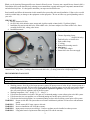
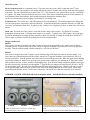
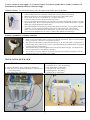
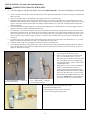
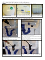
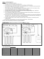
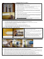
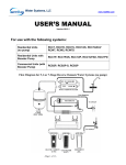
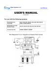
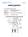
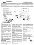
INSTALLATION & SERVICE MANUAL
Reverse Osmosis + DI Water Systems
Model:
RD-102
RD-106
6-Stage RO+DI system, 100GPD, single output
6-Stage RO+DI system, 100GPD, dual output s + tank+ faucet
PRODUCT SPECIFICATION
6- Stage Reverse Osmosis + DI Water Purification Systems
Model no: RD-102 and RD-106
Capacity: Generates 50 to 100 gallons per day depends on water temperature, pressure, chemistry variations)
System includes
• RO+DI unit: 6-stage unit, all filters included.
• Storage Tank (for RD-106 only): 4 gal. pressurized tank with pre-charge pressure of 7~10 psi., powder coated steel
construction with Food Grade butyl water bladder. NSF listed
• Water Dispensing Faucet (for RD-106 only): lead-free, long reach goose neck type, chrome steel, locking lever for
continuous dispensing.
• Hardware: feed water adapter, feed water valve, drain saddle valve, tank valve, and screws.
• Installation & Service manual
System Requirements
• Working pressure: 40 to 80 psi feed water pressure required, if below 40 psi, a booster pump is needed. We have a RO
system with booster pump assembly. If the input pressure is above 80 psi, you MUST put a pressure regulator to reduce
the pressure below 80 psi.
• Working temperature: 100 ~ 40 deg. F ( 37 ~ 4 deg. C )
• pH range: 2-11
• If feed water has hardness level above 300 ppm, we recommend putting a water softener prior to the RO system.
• If feed water has iron, rust problem, we recommend putting a iron filter prior to the RO system.
• If feed water has bacteria problem, we recommend putting an ultra violet sterilizing system prior to RO system.
Filter Service Life
• 1st Stage Sediment filter : Recommend changing every 6 ~12 months.
• 2nd Stage Carbon block filter : Recommend changing every 6 ~12 months .
•
3rd Stage Carbon block filter : Recommend changing every 6 ~12 months .
• 4th Stage TFC/TFM membrane: Recommend changing every 2~3 years.
• 5th Stage Inline carbon filter: Recommend changing every 6 ~12 months.
Replacement filter Part no.
Replacement filter Part no.
Replacement filter Part no.
Replacement filter Part no.
Replacement filter Part no.
201
205
205
399
213
The filters & membrane used are all standard sizes.
Dimension
• RO unit:
• Storage tank:
• Faucet:
Length 15 inch, Width 5 ½ inch, Height 16 inch
Diameter 10 ¾ inch, Height 15 ¼ inch (for RD-106 only)
9 ½ inch above counter top (for RD-106 only)
Warranty
• 1 years Limited Warranty on parts, components. Filters are not under warranty.
Performance
• Average Rejection rate: 92 to 98% of dissolved solids after RO, 98% to 100% rejection rate after RO+DI
Purification Processes/ Filter specifications
Removes microbiological contaminants like Cysts (protozoan), inorganic/Radiological contaminants like Barium,
Cadmium, Copper, Chromium (hexvavalent), Chromim (trivalent), Fluoride, Lead, Radium 226/228, Selenium, etc.
Ammonia, Arsenic, chloramines, chlorine, copper, lead, nitrate, phosphate, silica, hardness, calcium, magnesium, other
dissolved solids.
•
•
•
•
•
1st stage: 5 micron sediment filter, 2 3/4”. x 9 7/8” height, made by 100% pure polypropylene fibers
2nd & 3rd stage: carbon filter, 2 3/4” x 9 ¾” height, composed of high-performance coconut shell carbon.
4th stage: TFC/TFM type membrane, 100 GPD, 1 ¾” x 11 ¾” long
5th stage: DI filter, deionization filter, further removing dissolved solids.
6th stage: Inline carbon filter (polishing filter, improves taste): 2” x 10”
2
Thank you for choosing Watergeneral Reverse Osmosis Water Systems. You now own a superb Reverse Osmosis (RO) +
Deionization (DI) system that effectively reducing most contaminants, organic and inorganic compound, unwanted taste
and odor from tap water. It is designed to transform your tap water into distill water.
Read carefully and follow the instruction in this manual before proceeding with actual installation. Failure to do so could
result in personal injury or damage to the equipment or other properties. Be sure to follow any special plumbing codes in
your area.
CHECK LIST:
1. Reverse Osmosis+DI Unit
2. for (RD-106) which includes water storage tank, 4 gallon outside volume (holds 3.2 gallons @60psi)
3. Installation kit consists tank ball valve, drain saddle valve, feed water adapter, feed water needle valve, faucet
assembly(for RD-106) , tubing, tube inserts
4. Installation manual
INSTALLATION KIT:
1. Chrome dispensing faucet
(for RD-106 only)
2. Tank ball valve or On/Off valve
3. Drain saddle clamp
4. ¼” tubing
5. Bottom filter housing wrench
6. tube insert *
7. ½” feed water adapter
8. chrome ball valve for water supply
* NOTE: Item #6 tube inserts are not required in the installation, but you can put them in three places; (1) tubing
connection at 1st stage filter, (2) tubing connection at tank ball valve, (3) tubing connection at dispensing faucet.
RECOMMENDED TOOLS LIST
Variable speed drill
1/8” ¼”, 7/16”, ½”, and 5/8” drill bit
5/8, 9/16 open-end wrench, or adjustable wrench, pliers
Phillips screwdriver
Utility knife, or scissor
Teflon tape
OPERATING PARAMETER
• Working pressure: 40 to 80 psi feed water pressure required. If input pressure is below 40 psi, a booster pump or a
permeate pump is needed. We have a RO system with built-in permeate pumps, and we also carry booster pumps.
If the input water pressure is above 80 psi (you must use a pressure regulator to step down the pressure). We
also carry small pressure regulators just for the RO system.
• Working temperature: 100 ~ 40 deg. F ( 37 ~ 4 deg. C )
• If feed water has hardness level above 300 ppm, we recommend putting a water softener prior to the RO system.
• If feed water has iron, rust problem, we recommend putting an iron filter prior to the RO system.
• If feed water has bacteria problem, we recommend putting an ultra violet sterilizing system prior to RO system.
WARNING: Do not use this RO+DI system alone to treat water with bacteria problem or water source with unknown
quality.
WARNING: Do not connect HOT water source to this unit.
WARNING: Incorrect installation will VOID the warranty.
WARNING: Input pressure must not exceed 80 psi. Pressure regulator must be installed to reduce pressure.
WARNING: Using other brand of replacement filters and parts will void the warranty.
3
About the system
Reverse Osmosis process is a separation process. Tap water enters the system, and it is separated at the 4th stage
membrane filter. One side would go to the storage tank (purified water); the other side carrying all the minerals is purged
to the drain. The ratio of purified water to drain water is 1:3. That means for every gallon of water you use, it will drain 3
to 4 gallons. The drain is required for the RO process to work. If the drain is intentionally shut off, all the minerals will
be accumulated inside the membrane, and it would permanently damaged the membrane filter.
All Reverse Osmosis units require purging of water when it’s producing water.
Production rate: The system uses a 100 GPD (gallons per day) RO membrane. The actual production rate will depend
on water input pressure, temperature, and water chemistry. At optimal condition the membrane will make 110 GPD, but
on average, it would make about 60 to 70 gallons per day, or about 2.5 to 2.9 gallons per hour, or about 160 to 180 mL per
minute.
Drain rate: The drain rate of the system is set at 600 mL/min. using a flow restrictor. This drain rate is constant,
independent of input pressure. If the input water supply is very hard (> 17 grains) or the TDS reading is above 600 ppm,
it would be advantageous to change the flow restrictor to 800 or 850 mL/min. or change the membrane to 50GPD to 75
GPD, in order to get better rejection and prolong the life of the membrane filter.
Design consideration
RD-102
This system is designed to minimize the mineral content of tap water by using both reverse osmosis process and Deionization process. Tap water enters the system, and at 4th stage the membrane rejects about 90% to 95% of minerals to
the drain. Then the mineral content is further reduced by a series of two DI filters.
RD-106
This system is designed to provide 2 outputs; one for drin king water (RO) output, the other for DI water output. Tap
water enters the system through the first three filters, and then at 4th stage the membrane rejects about 90% to 95% of
minerals to the drain. Then the purified water (RO) water is stored in the pressure tank. When the output for the drinking
water faucet is turned on, the RO water goes out of the pressure tank, and then it goes through the 6th stage inline carbon
filter to improve the taste of water, and this is for drinking water. If the DI water output is turned on, then RO water goes
out of the pressure tank, and then it goes through the 5th stage DI filter, the output water would be RO+DI water. NOTE:
To achieve higher purity, the tank valve should be turned off when dispensing DI water. When the tank valve is turned
off, the purified water comes out of the system slowly which is the actual production rate of the system. When water
passes though the DI filter slowly, it allows more contact time with the DI resin, thus more minerals can be removed.
ASSEMBLY QUICK VIEW (RD-106, follow the photo below, for RD-102 filters are already installed)
Carbon
Carbon
Sediment
1. Remove plastic wrap on the filters (for RD-106)
2. Insert the filters as shown above.
1. Put upper portion of the unit on top of the filter housing
2. Screw on the filter housing vertically to the filter housing cap by
hand
3. Then use filter housing wrench to tighten the each housing
4
3 ways to connect to water supply: (1) Connect to faucet, (2) Connect to garden hose or laundry room hose, (3)
Install under the sink and connect to cold water supply
Connect to faucet: You can use the diverter valve to connect to the aerator part of your faucet.
1.
2.
3.
4.
5.
6.
Unscrew the tip or the aerator part of your faucet.
Connect tubing to the barb connection of the diverter valve by pushing in the tubing
Make sure the diverter valve threaded portion on the top has a s mall rubber gasket.
Screw on the diverter valve to the faucet tip. Use pliers if necessary.
Connect the other end of the tubing to the RO+DI system
Turn on your kitchen faucet all the way up, cold water. The water should come out of the valve like
regular faucet water. Then turn the lever 90 degree to divert water to the RO+DI system. (or for pullbutton type, just pull the button to divert water)
Then follow the photo on the next page for the other tubing connections. You can put the drain line
to the sink. It is not required to plumb the drain, just let it flo w to the sink or flow outside.
NOTE: The size provided is the most common size. If your faucet does not fit, you can buy
converter at local hardware store or call us, or choose other methods of connecting it.
7.
8.
Connect to garden hose or laundry room hose
1.
2.
3.
4.
5.
You can connect the ¾” garden hose adapter directly to a hose valve or to a hose.
Make sure the black rubber gasket is seating at the bottom of the thread. Then screw on the adapter
directly to the hose or hose valve. Use pliers if necessary.
The other end of the adapter is a Quick-connect fitting ¼”. So just push in the ¼” tubing about ½”
into the fitting, then it will seal itself. (Note: to disconnect tubing, just push the plastic ring against
the fitting, then pull out the tubing)
Then for other tubing connection, please refer to the picture shown next page. The drain line can
just run to open drain or to the laundry room drain.
You can also use a hose Y-connector to connect to the hose valve to have two outlets, so one for
the system and one for your laundry room washer.
INSTALLATION QUICK VIEW
Model: RD-102
Model: RD-106
A: DI water dispensing valve, on/off valve: blue tubing
B: Feed water valve or optional hose adapter or faucet diverter
: red or orange tubing
C: drain saddle clamp : black tubing
A:
B:
C:
D:
E:
5
Feed water valve: red or orange tubing
drain saddle clamp: black tubing
to pressure tank: yellow tubing
dispensing faucet: blue tubing
DI water valve: white tubing
INSTALLATION (for under-the-sink installation)
STEP 1: TAPPING INTO COLD WATER SUPPLY
CAUTION:
• The water supply to your RO unit MUST come from COLD water line . Hot water will damage your RO system.
1.
2.
3.
4.
5.
6.
7.
8.
Locate cold water shut off valve under the sink and turn it off. Open cold-water faucet to release the pressure, and make sure
there is no water.
Put 3 turns of Teflon tape on threaded ends of the angle needle valve, or the ball valve.
Determine the best location for putting the feed water adapter. Do you have a flexible line or a solid copper tube? Is the
flexible line with smooth surface or spiral line? Is there enough space for installing feed water adapter? More radius or more
space is required if you first joint the feed water adapter with the needle valve. Is the size of fitting thread the same as the
feed water adapter?
You can either joint the angle needle valve to the feed water adapter first, or install adapter to cold water supply line first. It
depends on how much space is available under the sink.
For FLEX line: Loosen nut and separate cold water riser tube from faucet shank. Gently bend riser tube so that feed water
adapter fits onto faucet shank. Use the Existing cone washer (if the existing cone water is badly damaged, use the new cone
water provided in the kit). NOTE: If you have a spiral type flex tube riser, you NEED to use the existing cone water, since
the cone washer we provided is straight, not spiral). Use Teflon tape on threaded parts to prevent leaks. Then tighten the
connection.
For Solid Copper riser: Same procedure as flex tubing except you must cut a piece of the riser tube about 3/ 4” to 1” so the
adapter can fit between faucet and riser tube. Use Teflon tape to prevent leaks.
Install the angle needle valve to adapter if you have not done so in procedure #4.
For connecting red tubing to angle needle valve, refer to the photo below. Then push tubing through the brass nut, then the
sleeve, then put plastic insert inside the tubing, then push sleeve against the insert, then screw on the brass nut. Don’t over
tighten it. But it has to be tight.
•
•
•
1. feed water adapter ½” connect to
base of kitchen faucet
1. buy a ½ pipe to ½” pipe hose
2. ½ to ½” nipple fitting. 3. adapter.
4. your existing faucet pipe
Many times, it is easier to use the existing
cone washer than using the new one.
If there is not enough space under the sink
base, or it’s difficult to get to, you can
disconnect the riser from the cold-water valve
side. If the fitting size does not match, buy
size-changing fittings, or buy a new flex riser
with matching sizes.
Many times, it is easier to buy an additional
stainless steel braded flex riser and a ½”
nipple to put in between the bottom of the
faucet male thread and the feed water adapter
(Don’t buy the spiral type) so you can easily
put the feed water adapter between two risers.
This is the EASIEST way. Spend additional
$5 on the riser may save you a lot of time.
Feed water adapter with Ball valve
1. put Teflon tape on the thread, put only 3 turns
2. push tubing through the nut,
3. push tubing all the way into the connection,
4. screw on the nut tight using a wrench
6
NOTE: The system uses compression fitting connections: When connecting tubing to
the system, first, you must unscrew the compression nut off the fitting, then pass the tubing
through the compression nut about 1”, then screw on to the fitting, then use a 5/8” wrench to
tighten the nut until the thread is not visible. Don’t over-tighten it.
STEP 2: INSTALLING THE DISPENSING FAUCET
1. faucet base
2. small washer+
chrome plate
3. large washer
4. kitchen sink
5. bottom plate
6. lock washer
7. lock nut
8. tube insert
9. sleeve
10. faucet nut
The faucet should be positioned with aesthetics, function
and convenience in mind. An ample flat surface is
required for the faucet base so that it can be drawn down
tight. Also check the under sink area of the desired
location to see if there is ample space to complete the
faucet installation.
If the space is not available on the upper sink area, the
faucet could be positioned on the counter top at the edge
of the sink. Be sure to watch for obstructions below, i.e.,
drawers, cabinet walls, support braces, etc. If the counter
top is ceramic tile, the method for drilling the hole should
be the same as for porcelain sink.
drill 5/8” hole on
the sink
NOTE: The sink drilling process, although not
complicated, requires a certain amount of caution and
forethought. Porcelain sink can chip if care is not
exercised.
PORCELAIN ENAMEL SINK/ STAINLESS STEEL SINK/ ALUMIUM SINK
A 5/8” hole is required for the faucet. It is recommended that you get special drill bit for porcelain and tile counter.
1. Place a piece of masking tape or duct tape on the determined location where the hole is to be drilled.
2. Use a variable speed drill at slow speed with 1/8” drill bit, and drill a centering hole in the center of the desired
faucet location.
3. Enlarge the hole using a 1/ 4” drill bit.
4. Enlarge the hole using 7/16”, 1/ 2”, and 5/8” drill bit. Pause occasionally to cool drill bits.
5. File or clean the surrounding area and remove the masking or duct tape. (NOTE: the metal chips on porcelain will
stain very fast)
6. DON’T put Teflon tape at the tip of the threaded mounting base of the faucet since it’s a compression fitting.
7. Put the small rubber washer, the chrome base plate, large rubber washer according to the diagram through the
threaded mounting tube at the base of the faucet.
8. From under the sink, install the bottom plate, lock washer, and nut. Then screw on tightly.
9. According to the diagram, put the brass nut through the BLUE tubing first, then plastic sleeve (preferred), or brass
sleeve, then the plastic insert. Push the white plastic sleeve against the insert.
10. Screw on the Blue tubing with brass nut to the faucet base. Uses wrench to tighten the nut but don’t over tighten
it. Too tight would cause leak.
11. The spout can swivel 360-degrees. The faucet lever can be pushed down for dispensing or pulled up for
continuing dispensing.
7
STEP 3: MOUNTING THE TANK BALL VALVE (for RD-106 only)
Do not release air from the air valve on the lower side of the storage tank. It is pre-charged at 7 psi at the factory.
put Teflon tape, 6-8 turns
screw on ball valve hand tight, push tubing
through the nut, put tube insert, screw on the
nut
the tank can be positioned
laying down or standing upright
STEP 4: MOUNTING THE DRAIN SADDLE VALVE (don’t put in blue area)
The drain saddle valve should fit most standard drain pipe. It
should be installed above the trap and on the horizontal pipe
(1) or vertical pipe (2).
DON’T put on position (3), (4), or blue section
Align the drilled hole in the drain pipe with the drain saddle
using a drill bit or narrow screwdriver
Position the drain saddle in desired location, mark spot. You need
to consider available space for drain tubing
Drill 1/ 4” hole into the drainpipe above the water line of the pipe.
Clean the surface of the pipe.
Pear off the sticky foam pad, then align the center hole around the
drilled pipe hole. Then tape it.
put the complementary piece and clamp them together with the
two bolts. (1) Tighten the two bolts evenly. (2) Connect tubing
8
STEP 5: SYSTEM START-UP
1. Make sure all tubing are not kinked.
2. Turn Tank Valve to OFF position. (for RD106 only)
3. Turn RO faucet lever to continuous flow position. Lever points up. (for RD-106 only)
4. Turn cold water supply main valve on slowly. Also turn input ball valve ON. When the system is pressurized,
check for leaks. If a leak is found, tighten the connection.
5. Wait 5 minutes, the water should start dripping out of the RO faucet, and then wait 10 more minutes to allow
water to flow through the system, and air inside the system can be purged.
6. Turn Tank Valve to ON position, lever is parallel to the tubing. (for RD-106 only)
7. Turn the RO faucet lever to OFF. Now the purified water will start filling the storage tank. (for RD-106)
8. Wait 2 hours for the storage tank to be filled up.
9. DO NOT DRINK THE FIRST BATCH OF WATER PRODUCED BY THE SYSTEM. For RD-102 let pure
water drain out for about 1 gallon before start using the water.
10. After storage tank is full, turn the RO faucet lever to continuous flow position, (Lever points up) to discharge the
first batch of water. It takes about 5 minutes to completely discharge the tank. When the tank is discharged, you
will notice just a steady trickle of water coming out. (for RD-106 only)
11. After discharging the tank or about 5 minutes, turn the RO faucet to OFF position. Now the RO system is
refilling the tank.
12. After the tank is fille d up again, you can start enjoy the purified water. Job Well Done!
NOTE: Check for leaks daily for the first week after installation.
Flow Diagram for 6-Stage Reverse Osmosis+ DI Water Systems
MODEL: RD-102
MODEL: RD-106
SERVICE RECORD:
DATE OF PURCHASE:
DATE OF INSTALLATION/SERVICE:
Service Date
Date
1st stage sediment
2nd stage carbon
3rd stage carbon
4th stage membrane
5th stage DI filter
6th stage inline carbon
Date
Date
9
Date
Changing Filters Procedures
•
•
•
•
•
•
•
•
•
•
Shut off the system by turning off the water supply, and turn off the tank valve, open
the spigot to depressurize
Prepare a towel under the unit for water spills
Use a filter wrench (part no. 566) or use hands to open the filter housing, unscrew it
from right to left. To open is clockwise looking from the top.
Throw away the used filter, and clean the inside of the housing by rinsing or
scrubbing it with dish soap.
Check condition of the O-ring. It should be replaced every 3 years to prevent leak
Place the new filter inside the filter housing. For carbon filters, the rubber gaskets
should be on both ends.
Put some Vaseline or silicon-based O-ring lubricant on the side of the housing thread
and the O-rings (optional procedure)
Use a filter wrench or both hands to screw the housing back by turning it from left to
right (Don’t lay down the unit when turning it, the unit should be standing upright to
prevent the o-ring or filters from misalignment)
Repeat the above steps for other filters
The 6 th stage inline carbon filter has penny-sized protective caps on both ends.
Please use a screw driver or knife to pry open the caps.
Replace resin: (clear inline filter)
1.
2.
3.
4.
5.
6.
7.
Turn off the water supply valve and tank valve. Turn on the output valve to release pressure
Disconnect tubing from both ends of the clear DI filter. Lift the filter from the U-clip and unscrew one end off
Pour out the used DI resin. Refill new resin with a spoon or just pour in
Fill all the way to the top about 95% full.
Clean the threads on the cap and on the filter using brush or rinse under water
NOTE: The threads must be very clean. Even a single grain of resin will cause a leak.
Connect tubing back and turn on water supply valve and tank valve, and check for leaks.
Replace inline carbon filter: (white inline filter)
* if you have compression fitting
*unscrew fitting off to replace
filter
For part no. 213 inline carbon filter, remove fittings from both
ends of the filter then replace new filter.
After all housings are tight, turn on the water supply and tank
valve.
Check for leaks, if there is a leak; tighten the housing or realigning the o-ring.
Open the spigot to drain all the water out of the storage tank.
If you are changing a carbon filter or membrane, you must
drain the first tank of water after restart the system.
Refer to the next page for recharging tank procedure (if
necessary)
Changing Membrane Procedure
•
•
•
•
•
•
Lift the membrane housing from the U-clips, and remove the tubing from the membrane fitting (the inlet side of the membrane
housing, or the side with the membrane housing cap). Unscrew the membrane housing cap off (counter-clockwise)
Use pliers to pull the membrane out of the membrane housing, and discard the used membrane.
Put some Vaseline or lubricant on the small black O-rings. Insert the new membrane into the me mbrane housing (THE SIDE WITH
DOUBLE BLACK O-RINGS SHOULD GO IN FIRST) Push the membrane all the way in (some force is required to make sure the
membrane is all the way in). Put some Vaseline or silicon based lubricant to the side of the housing threads.
Screw the membrane-housing cap back (clockwise). Make sure O-ring is in place. Connect the tubing to its elbow fittings.
Turn on the water supply and tank valve to restart the system. Check for leaks, if there is a leak, tighten the cap
Wait 2 to 3 hours for the tank to be filled then you must drain the first tank of water by opening up the spigot to flush the system.
10
TROUBLE SHOOTING
* For more detailed tech support notes & troubleshooting go to
NOTE: Turn off the system before servicing.
Installation Troubleshooting
PROBLEM
POSSIBLE CAUSE
No or low water production 1. Feed water valve in not turn on
2. Tank valve is not turn on
3. Tubing is kinked
1. Housing is not tighten
Leak at filter housing
2. Damaged or misaligned O-ring
3. Housing has cracks
Leak at fitting thread
1. Not properly tighten
2. Fitting has cracks
Bad-tasting water
1. Not yet flush the system
2. Tubing connection incorrect
Milky/Cloudy water
1. Air in system/filters
1. Saddle valve mounted too high
Noise from drain
Troubleshooting
PROBLEM
When turn on the RO faucet,
only small amount of water
come out.
Vibrating noise or very loud
high pitch noise
Drain water never shut off
Low water production
www.watergeneral.com
SOLUTION
1. Turn on feed water valve
2. Turn on tank valve
3. Straighten the tubing
1. Tighten housing
2. Re-aligned O-ring or replace
3. Replace housing
1. Use Teflon tape, re-tighten
2. Replaced it
1. Discharge water from tank
2. Check flow diagram
1. This is normal, continue use it for 2 weeks
1. Lower the saddle valve
When system is making water, waste water to
drain is normal, when storage tank is full, drain
should stop
POSSIBLE CAUSE
1. Lifting the tank to see if there is
still water inside. Heavy or light ?
1. From the auto shut-off valve
1. Auto shut-off valve is worn out
or becoming ineffective
2. Storage tank not enough pressure
3. Water supply pressure is near 40
psi or below
4. Cold water temperature
5. Filters are clogged up
1. Storage tank problem
2. Clogged filters
3. Kinked tubing
4. Clog flow restrictor
SOLUTION
1. If it’s heavy, you need to recharge tank,
following recharge procedure
1b. If its light, the water either is not going
in or the system is not making water.
1. If the noise is too unbearable, shut-off
valve should be replaced.
1. Replace auto shut-off valve
2. Follow recharging tank procedure
3. Increase feed water pressure
4. Can’t do anything about it.
5. Replace filters
1. Follow recharging tank procedure
2. Replace filters
3. Straighten the tubing
4. Replace flow restrictor
Note : Clogged filters: How do you know if the filters are clogged up? For the pre-filters, sediment filters and carbon
filters; check the pressure difference before and after the filters. If there is significant difference in pressure that means
the filter is clogged. Turn OFF tank valve and cold water main valve then open the RO faucet to depressurize the system,
then disconnect the tubing after the bottom three pre-filters, then turn ON the cold water main valve. If you get very
strong water pressure, (as strong as water going into the system) then the bottom 3 pre-filters are not clogged. If the water
pressure is much smaller, unlike a burst of water pressure, then the bottom 3 pre-filters need to be replaced. Note :
Checking a clogged membrane uses different method. Use a water quality meter TDS meter to check the condition and
performance of the RO membrane (4th stage filter)
Note : Clogged flow restrictor: When you disconnect the black tubing going into the saddle valve, and the RO system is
in the processing of making water (by turning on the RO faucet), there should be a small steady flow of drain water. If
you do not get any drain water, the flow restrictor may be clogged, then you need to replace a new flow restrictor ASAP,
and discontinue using the system.
11
RECHARGING TANK PROCEDURE
PROBLEMS:
•
•
•
When you turn on the spigot you get small water pressure and water flow.
When you turn on the spigot, only a quick burst of water comes out of the system, then it dies down to
trickles.
When you turn on the spigot in the morning, you only can get less than a gallon of water.
If you have above problems, you should recharge the tank. The tank should have about 7 psi of air pressure
when it is completely empty. The storage tank has a water bladder inside, and it is surrounded by compressed
air, so when you turn on the spigot, the compressed air would squeeze or compress the water bladder to force
the water out of the tank. When the tank is full the tank pressure can reach about 35 to 50 psi depending on
your feed water pressure, but to accurately recharge the storage tank, you should empty the tank then set the air
pressure to 7 psi.
TOOLS NEEDED: An air compressor or air pump (like a bicycle tire air pump. An air pressure gauge that is
able to read less than 10 psi. Adjustable wrench or 9/11” wrench
STEPS:
1. Shut off the water supply to the RO system. Turn on the spigot to allow water to run until it stops (you can
collect the water if you want)
2. Check to see if there is still water in the storage tank by lifting the tank. If the tank feels heavy, that means
you need to recharge to tank, then continue the following steps. If the tank feels light, that means you don’t
need to recharge your storage tank at this time.
3. Locate the air valve on the side or on the bottom of the tank. It looks like the air valve on tires.
4. Use an air compressor or air pump to pump air into the tank. Keep the spigot on while pumping air, so that
all water inside the tank can be purged out. Don’t over charged it, just keep around 20 psi.
5. After all water is been discharged, use an air pressure gauge to check the tank pressure.
6. The tank should have 7 psi of pressure when it’s empty. Add or purge air if necessary.
7. Turn the feed water valve back on, and turn off the spigot to allow refilling of the tank. It may take couple
hours to refill the storage tank.
8. Finished
NOTE: If after few days of running the system, the problem comes back, then you may need to replace a new
tank.
12
LIMITED ONE-YEAR WARRANTY
1. What your warranty covers:
WaterGeneral Reverse Osmosis+DI Systems are warranted to the original owner to be free of defects in material
and workmanship from the date of manufacture for two years as follows:
a. Manufacturer will, within one year of purchase, replace the defected parts (excluding filters) at no charge.
b. The replaceable filters are not warranted since the service life of replaceable filter varies with local water
conditions and thus not warranted.
2. Conditions of Warranty:
a. System must be maintained and serviced with the manufacturer original replacement parts and filters.
The performance of your drinking water system is directly related to the conditions of the water been
treated and the particular application in which it is used. Therefore, manufacturer’s liability is limited to
the cost of repair of the RO+DI system. The manufacturer is not liable for incidental or
consequential damages of any kind. Systems must be installed and operated in accordance with
manufacture’s recommended procedures and guidelines.
3. What WaterGeneral Reverse Osmosis+DI Systems will not do:
a. Warranty is void if product failure or damage results from freezing, neglect, misapplication, fouling with
sediment or scale or failure to operate the system in accordance with the instructions contained in this
manual.
b. The following operating conditions must also be followed for this warranty to be valid
• The hardness of the water cannot exceed 7 grains per gallon or 120 ppm.
• No iron can be present in feed water. Or iron should be removed from feed water.
• The pH of the water must not be lower than 3 or higher than 11
• Feed water Total Dissolved solids TDS should not exceed 1000 ppm
• Feed water temperature between 90 F and 45 F or (32C and 5 C)
4. Obtaining Warranty Service:
For Warranty service, obtain a Return Merchandise Authorization (RMA #) number from the manufacture or
distributor. You can also contact our technical support department to obtain the RMA # or visit our web site at
http://www.WaterGeneral.com or email your request to [email protected]
5. Limitations and exclusions:
Manufacturer will not be responsible for any implied warranties, including those of merchantability and fitness
for a particular purpose. Manufacturer assumes no liability whatsoever for any incidental and consequential
damages, including loss of revenue, loss of time, travel expenses, inconvenience, and any damage caused by the
equipment and its failure to function properly.
13