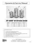
1
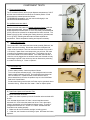
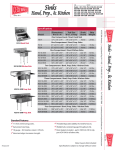
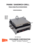
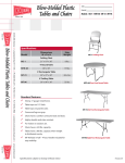
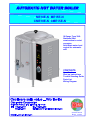
ME10E-N ME15E-N
CME10E-N CME15E-N
18 Gauge Type 304L
Stainless Steel
construction to resist
corrosion.
Solid State water level
control for automatic
refill
CONTENTS
Specifications
Start up Instructions
Trouble Shooting Guide
Parts List
Wiring Diagram
Operation Manual
NP57A 10-2006
VENT OPENING
POWER
SUPPLY BOX
POWER ON
LIGHT
ME10E-N
CAUTION
HOT SURFACES
HEATER ON
LIGHT
POWER
SWITCH
TEMPERATURE
CONTROL
"A"
TEMPERATURE CONTROL
4.0
SIDE ACCESS DOOR
(SLIDES UP)
OVERFLOW
THERMOMETER
14.0
WATER INLET
4.0
3.4
16.0
NOTE:
1. FIELD WIRING MUST BE SUITABLE FOR 75 DEGREES CELSIUS.
2. USE COPPER WIRE ONLY FOR POWER SUPPLY CONNECTION.
3. 120 VOLT UNITS SUPPLIED WITH A GROUNDED 120V-15A LINE CORD AND PLUG.
AUTOMATIC
HOT WATER BOILER
WARRANTY
Every Cecilware product has been carefully inspected before shipment. The finest materials and the highest
standards of workmanship have been built in to the equipment.
Within 1 year of purchase, should any Cecilware product show defect in factory workmanship or material,
we agree to repair at our option or replace without cost to user, such parts which prove upon factory
inspection to have been so defective. All equipment must be shipped transportation charges prepaid for
acceptance. This warranty covers replacement parts only; labor charges are covered for 90 days after
installation.
This warranty does not apply under the following conditions:
• neglect or abuse of equipment
• excessive lime condition
• improper installation
• any outside modification to equipment
Every Cecilware urn body is covered for three years. This warranty covers the stainless steel body and
stainless steel liners only.
Portable equipment such as Electric Fryers, Food Warmers, Electric Stoves, Dispensers, Plug-In Urns, Coffee
Brewers and Warmers must be returned to the factory or brought to an authorized service station for repair.
UNPACKING INSTRUCTIONS:
Carefully unpack the water boiler and inspect immediately for shipping damages. Your automatic water
boiler was shipped in a carton designed to give maximum protection in normal handling. It was thoroughly
inspected before leaving the factory and the carrier accepted and signed for it. File any claims for shipping
damage or irregularities directly with the carrier.
ASSEMBLY:
The four legs, faucet, vent cap drain, and hose nut are packed separately with the water boiler. Install legs
by tilting the water boiler on its side and screwing the legs in the leg supports until hand tight. Carefully
right the unit and install it in its permanent location, being sure to leave at least 6” on the right side of the
water boiler for access to the controls. Level the unit by adjusting the bottom pad of the legs. Place the vent
cap in to the recess in the top of the unit. Mount the faucet assembly on to the shank.
INSTALLATION INSTRUCTIONS FOR WATER BOILERS
Water boilers are shipped with the thermostats in the OFF position. Do not turn the thermostat on before
filling the water boiler with water.
NOTE: When positioning the unit, leave a minimum of 6” clearance on the right side of the water boiler for
ease of service.
ELECTRICAL HOOK-UP PROCEDURES:
FOR QUALIFIED SERVICE PERSONNEL ONLY
NOTE: Always check the rating plate of the unit for proper voltage and current requirements.
1.
120V water boilers are provided with 120V/15A grounding plug. Units must have a separate
120V/15A outlet.
2.
208/240V water boilers are provided with a terminal block inside the control box. Field wiring must
be performed by a qualified serviceman. 1 and 3 phase hook-up for units with terminal blocks. To
access terminal block, remove the fastener on the cover and slide off cover. Install a suitable conduit
and connect copper wires to terminal L1 and L2 (and L3 for 3 phase unit only) and a #14 AWG
ground wire to the ground lug.
WATER HOOK-UP PROCEDURE:
Water Inlet Connection:
This equipment is to be installed to comply with the applicable Federal, State, or local plumbing codes having
jurisdiction. In addition:
1. A quick disconnect water connection or enough extra coiled tubing (at least 2x the depth of the unit) so
that the machine can be moved for cleaning underneath.
2. An approved back flow prevention device, such as a double check valve to be installed between the
machine and the water supply.
The unit is equipped with a ¼" Flare Water Inlet Fitting which is located on the back of the control box.
NOTE: Connecting the water boiler to a warm water supply will speed up heating and recovery times.
HIGHLY RECOMMENDED:
A WATER SHUT-OFF VALVE and A WATER FILTER, preferably a combination Charcoal/Phosphate
Filter, to remove odors and inhibit lime and scale build up in the unit.
Note: In areas with extremely hard water, a water softener must be installed in order to prevent a
malfunctioning of the equipment and in order not to void the warranty.
PRIMING AND FILLING A UNIT:
Connect unit to power line (plug cord into line for 120V unit or turn on switch for the 208/240V units). Turn
on the water supply. The unit fills at the rate of 1 gallon per minute. When the water level becomes visible in
the sight gage, turn the thermostat clockwise to maximum position. The unit will now automatically fill to
capacity and heat the water.
CLEANING INSTRUCTIONS:
DAILY: Wipe the outside of the unit with a damp cloth, using soap solution or a non-abrasive compound
when required.
SANITIZING THE UNIT:
With power to the unit disconnected, fill unit to capacity. Add 1 ounce of CLOROX BLEACH (5.25%) for
every gallon of water in the unit (400 PPM). Let the solution stand in the unit for 15 minutes, then drain all
water from the unit slowly. If the unit is not to be used again immediately after sanitizing—do not rinse with
water. If the unit is to be used immediately after sanitizing—rinse with water before refilling the unit for
further use.
COUPLING
COMPONENT TESTS
A) Thermostat Adjustments:
The Thermostat is factory set for proper dispense temperature of 190° F
with the control shaft set to the maximum clockwise position. If field
adjustments are needed proceed as follows:
To DECREASE temperature, turn the control shaft slightly in the
COUNTERCLOCKWISE direction.
NUT
- CCW - DECREASES
TEMPERATURE
For qualified technicians ONLY:
Remove the knob and locate the Slotted Adjustment Screw inside the
hollow thermostat shaft. Using a narrow-bladed screwdriver, engage
slotted adjustment screw and turn it ¼ turn very slowly counterclockwise
(CCW). Allow a few minutes for the temperature to reach set level. The
Heater Light will go ON, indicating the heating element is activated, wait
for it to go OFF, indicating that the water has reached NEW set
temperature. Take a temperature reading and repeat if necessary.
B)
THERMOSTAT BULB
Water Inlet Valve Test
HOSE NUT ASSY
Turn power OFF. If the water level rises inside a partially filled tank, the
Water Inlet Valve is leaking. Disconnect wires from the Water Inlet
Valve coil and connect a 2 wire line cord to the terminals. Plug it into a
115V outlet. If water flows in and stops when you pull it out, the Valve
is working fine. Repeat this test a few times. The problem may be in
the Probe or Water Level Control Board. If the water does not flow in
when the cord is plugged into an electrical outlet, the Solenoid coil may
be damaged, opened or the valve may have an obstruction preventing
the water from flowing in. Clean or replace it.
WATER INLET VALVE
C) Dual Probe Test
BLUE
If lack of water persists, check the probe as follows:
Turn on the power and water supply. Check inside the tank to make
sure the water is below the Probe. Pull the BLUE wire and terminal
OFF the Probe rod. If water still does not flow after the wire is
disconnected from the Probe, the problem may be in the Solid State
Dual Level Control Board.
If water starts flowing into the tank, the Probe may be grounded, due to
excessive liming. Check with Ohm meter. Clean or replace probe.
DUAL PROBE
D) Dual Probe Liquid Level Controller Test
Check the Controller as follows:
1. Make sure there is power input to the Controller at the terminals AC1
& AC2
Your voltmeter should read 115 Volts. It should read the same at
terminals AC1 & FILL when the water level is low. This is the output
power to actuate the coil of the Solenoid Valve to open it. The lack of
voltage at terminals AC1 & L-LEVEL or H-LEVEL indicates that the
Controller is not working properly.
2. Make sure all wire connections are tight, including ground.
3. If after this, the Controller is still failing to open the Water Inlet Valve,
replace it.
DUAL PROBE CONTROLLER
20
19
18
2
5
19
4
3
2
1
ME10E-N
ME15E-N
28
27
26
25
24
23
22
21
13
12
11
10
9
8
6
7
ITEM
DESCRIPTION
17
16
15
14
ME10E-N
19
2
ME15E-N
QTY
ELECTRICAL DIAGRAM ME10E-N, ME15E-N
120 VOLTS
N
L1
WATER LEVEL CONTROL
WATER INLET
VALVE
GND
RED
WHT
WATER LEVEL
PROBES
BLU
YEL
GRN
1 FILL
2 AC-1L
3 AC-2N
4 L-LEVEL
5 H-LEVEL
6 COMMON
LED
WATER
GND
HEATER LIGHT
HI-LIMIT SWITCH
THERMOSTAT
ON-OFF
HEATER
G199A (1.8 KW)
POWER LIGHT
POWER SWITCH
N
L1
SHEET 1 of 4
CECILWARE CORPORATION
ELECTRICAL DIAGRAM ME10E-N, ME15E-N
120/ 240 VOLTS
N
L1
WATER LEVEL CONTROL
WATER INLET
VALVE
GND
RED
WHT
WATER LEVEL
PROBES
BLU
YEL
GRN
1 FILL
2 AC-1L
3 AC-2N
4 L-LEVEL
5 H-LEVEL
6 COMMON
LED
WATER
GND
HEATER LIGHT
HI-LIMIT SWITCH
CONTACTOR
THERMOSTAT
ON-OFF
(SEE HEATERS HOOK-UP SHEET 4)
POWER LIGHT
POWER SWITCH
N
L2
L1
SHEET 2 of 4
CECILWARE CORPORATION
ELECTRICAL DIAGRAM ME10E-N, ME15E-N
240 VOLTS
L2
L1
WATER LEVEL CONTROL
WATER INLET
VALVE
GND
RED
WHT
BLU
YEL
GRN
WATER LEVEL
PROBES
1 FILL
2 AC-1L
3 AC-2N
4 L-LEVEL
5 H-LEVEL
6 COMMON
LED
WATER
GND
HEATER LIGHT
THERMOSTAT
ON-OFF
HI-LIMIT SWITCH
CONTACTOR
(SEE HEATERS HOOK-UP SHEET 4)
POWER LIGHT
L3
L2
POWER SWITCH
L1
SHEET 3 of 4
CECILWARE CORPORATION
ELECTRICAL DIAGRAM ME10E-N, ME15E-N
240 VOLTS
HEATERS HOOK-UP
N
L1
L2
CONTACTOR
TERMINAL
BLOCK
1 PHASE 240 VOLTS
G197A (2 x 3.5 KW)
TOTAL: 7 KW
N
L1
L2
L3
CONTACTOR
3 PHASE 240 VOLTS
G197A (3 x 3.5 KW )
TOTAL: 10.5 KW
CECILWARE CORPORATION
TERMINAL
BLOCK
SHEET 4 of 4