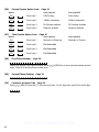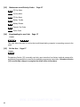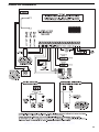
1
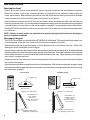
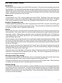
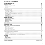
TABLE OF CONTENTS
INTRODUCTION
3
Features .................................................................................................................................................. 3
Specifications .......................................................................................................................................... 3
INSTALLATION
4
Mounting the Panel ................................................................................................................................. 4
Mounting the Keypad .............................................................................................................................. 4
Wiring ...................................................................................................................................................... 5
Burglary Zone Wiring .............................................................................................................................. 5
Auxiliary Power Connection .................................................................................................................... 5
PGM Terminal Connections .................................................................................................................... 5
STR Terminal Connection ....................................................................................................................... 5
KEY Terminal Connection ....................................................................................................................... 6
AC Power Wiring ..................................................................................................................................... 6
Battery Connection ................................................................................................................................. 6
Telephone Line Wiring ............................................................................................................................ 6
KEYPAD FUNCTIONS
7
Introduction ............................................................................................................................................. 7
Master Code ............................................................................................................................................ 7
Installer’s Programming Code ................................................................................................................ 7
Arming ..................................................................................................................................................... 7
Auto-Bypass/Stay-Away Arming ............................................................................................................. 7
At-Home Arming ...................................................................................................................................... 7
Disarming ................................................................................................................................................ 8
∗
Important Note about Keypad [ ] Commands ...................................................................................... 8
∗
∗
[∗]+[2]:Display Trouble Conditions ....................................................................................................... 8
[∗]+[3]:Display Alarm Memory .............................................................................................................. 9
[∗]+[4]:Bell Test ..................................................................................................................................... 9
[∗]+[5]+[Master Code]: Program Access Codes ................................................................................. 9
[∗]+[6]:Door Chime On/Off .................................................................................................................... 9
[∗]+[7]:Utility Output Command ............................................................................................................ 9
[∗]+[8]+[Installer’s Code]: Installer’s Programming Command .......................................................... 10
[∗]+[9]+[Access Code]: At-Home Arming ........................................................................................... 10
[ ]+[0]:Quick-Arm .................................................................................................................................. 8
[ ]+[1]+[Access Code]: Zone Bypassing ............................................................................................. 8
Keypad Zones ....................................................................................................................................... 10
Adjusting the Keypad Sounder Tone and Backlighting ....................................................................... 10
WWW.DIYALARMFORUM.COM
1
PROGRAMMING GUIDE
11
Sections [05] through [07]: Enabling System Functions ...................................................................... 11
HEX Data Programming ........................................................................................................................ 11
Resetting Programming to the Factory Default Settings ....................................................................... 12
PROGRAMMING SECTIONS
13
[01] Zone Definitions ........................................................................................................................... 13
[02] System Times ............................................................................................................................... 14
[03] Installer’s Code ............................................................................................................................ 14
[04] Programmable Output Options (PGM Terminal) .......................................................................... 14
[05] First System Option Code ............................................................................................................ 15
[06] Second System Option Code ...................................................................................................... 15
[07] Third System Option Code ........................................................................................................... 16
[08] First Phone Number ..................................................................................................................... 16
[09] Second Phone Number ................................................................................................................ 16
[10] Customer Account Code ............................................................................................................. 16
Disabling Communications ................................................................................................................... 16
[11] Zone Alarm and Restoral Reporting Codes ................................................................................ 16
[12] Opening and Closing Reporting Codes ...................................................................................... 16
[13] Maintenance and Priority Codes ................................................................................................. 17
[14] Downloading Access Code ......................................................................................................... 17
[15] Do Not Use ................................................................................................................................... 17
FOR THE RECORD
18
PROGRAMMING WORKSHEETS
19
HOOK-UP DIAGRAM
23
LIMITED WARRANTY
24
WWW.DIYALARMFORUM.COM
2
INTRODUCTION
FEATURES
SPECIFICATIONS
• Fully featured security system with Trouble
Supervision, Alarm Memory, Master Code and 3
programmable Access Codes, Quick-Arming and
At-Home Arming, Door Chime, 3 one-touch Keypad
Zones, and more
• Digital Communicator with programmable
Communication Formats (20 bps 3/1, 4/1, 4/2)
• 4 End-of-Line Resistor Supervised Zones
• 6 Programmable Zone Types with Silent or Audible
alarms
• Programmable Output with 4 options
• Dedicated Strobe (latched alarm) Output
• Momentary or Maintained Keyswitch Arming
• All Installer’s Programming can be done at the
keypad or through downloading
• EEPROM memory retains all programming even
after all power is removed from the control panel
• Advanced static and lightning protection; unique
“Zap-Trac” circuit board design stops damaging
voltages at the wiring terminals, and transient
protection devices are placed in all critical areas for
further protection
PC560 Control Panel
• Four fully programmable zones
• Zones are End-of-Line Resistor supervised
• All zones programmable as 24-Hour Pulsed Alarm
zones
• Maximum zone loop resistance: 100 ohms
• Bell/Siren Output: fused for 5A
• Bell / Siren Alarms: steady and pulsed alarms
• Programmable Output: 50 mA with 4 options
• Auxiliary Power Output:
• 800 mA with 40 VA transformer
• 500 mA with 20 VA transformer
• Maximum 3 Keypads per system, and Keyswitch
operation
• Required Battery: 12 VDC
• 1.2 Ah provides 4 hours of stand-by at
200 mA Auxiliary Output
• 4.0 Ah provides 4 hours of stand-by at
800 mA Auxiliary Output
• Required Transformer: 16 VAC, 20 - 40 VA
• Panel dimensions: 7" high × 9" wide × 3" deep
(178 × 229 × 76 mm)
• Panel Colour: light beige
PC500RK Keypad
• 12-key keypad
• Three one-touch Zones: [F], [A], [P]
• 3 Status Lights: Ready, Armed, System
• 4 Zone Lights
• Keypad dimensions: 4.5" high x 4.5" wide x 1"
deep (114mm x 114mm x 25.4mm)
• Keypad Colour: Mist
SL-40 Keypad
• 12-key keypad
• Three one-touch Zones: [F], [A], [P]
• 3 Status Lights: Ready, Armed, System
• 4 Zone Lights
• All new slimline design
• Keypad dimensions: 4.75" high x 2.75" wide x 1.2"
deep (120mm x 70mm x 30mm)
• Keypad Colour: Designer White with Grey display
WWW.DIYALARMFORUM.COM
3
INSTALLATION
Mounting the Panel
Select a dry location close to an unswitched AC source, a ground connection, and the telephone connection.
Remove the printed circuit board, mounting hardware and keypad from the cardboard retainer inside the
control panel cabinet. Before attaching the cabinet to the wall, press the four white nylon printed circuit board
mounting studs into the raised mounting holes from the back of the cabinet.
Hold the cabinet in position and pull all wires into the cabinet. Mount the cabinet securely to the wall using the
mounting screws provided. It is recommended that appropriate wall anchors be used when securing the panel
to drywall, plaster, concrete, brick or other similar surfaces using #8x1” round headed screws (or equivalent).
Press the PC560 Control Panel onto the nylon mounting studs. Pull all cables into the cabinet and prepare them
for connection.
NOTE: All holes in metal which have insulated wires passing through them should have bushings to
prevent insulation breakdown.
Mounting the Keypad
The PC560 Control Panel is controlled with the PC500RK or SL-40 Keypad. The Keypad should be located close
to the designated “Entry-Exit” door and mounted at a height convenient for all users.
Disassemble the keypad by pressing gently on the locking tab found on the bottom of the unit. With the tab
disengaged, pull the backplate from the keypad.
Prepare a hole in the wall at the desired location and pull the keypad wiring through the hole. Hold the backplate
in position and pull the wires through the large opening in the backplate. Mount the backplate to the wall using
the hardware provided; it is recommended that plastic wall anchors be used. When mounting the backplate,
ensure that it is straight and level.
Prepare all wires for connection and connect the keypad wires to the in-wall wiring; refer to the Wiring Diagram
in the back of this manual.
Align the keypad with the mounting tabs on the top of the backplate. With the top mounting tabs engaged, swing
the keypad down and engage the bottom locking tab. Ensure that the top mounting tabs and the bottom locking
tab are securely engaged.
SL-40 Keypad
1
2
3
PC500RK Keypad
4
Ready
LOCKING TAB
Armed
LOCKING TAB
System
Zone 1
Zone 2
Zone 3
Zone 4
PC500RK KEYPAD
BOTTOM VIEW
SL-40 KEYPAD
BOTTOM VIEW
ENGAGE TOP TABS FIRST
WALL
RE-ASSEMBLY OF
SL-40 KEYPAD
SIDE VIEW
(WIRES NOT SHOWN
FOR CLARITY)
SWING KEYPAD DOWN
TO ENGAGE LOCKING TAB
ENGAGE TOP TABS FIRST
WALL
RE-ASSEMBLY OF
PC500RK KEYPAD
SIDE VIEW
(WIRES NOT SHOWN
FOR CLARITY)
SWING KEYPAD DOWN
TO ENGAGE LOCKING TAB
WWW.DIYALARMFORUM.COM
4
Wiring
NOTE: Complete all wiring to the control panel before applying battery or AC power.
If the neutral in the main supply is not readily identifiable, then an appropriate disconnect device that has
a contact separation of at least 3mm and disconnects both poles simultaneously, must be used.
In order to comply with safety requirement IEC950, ensure that when the mains cabling enters the alarm
panel, it is securely clamped to prevent it from being removed.
Interconnection circuits should be such that the equipment continues to comply with the requirements of
IEC950 when like circuits are connected to each other. For example, TNV (telephone network) circuit should
be connected to the TNV circuit, SELV (zoned) circuits should be connected to SELV.
Burglary Zone Wiring
Burglary zone definition, (for example, Delay, Instant, 24-Hour, and so on) is programmed using the keypad.
Refer to Programming Guide Section [01].
Z1
COM Z2
Burglary Zone Wiring Chart
NC
EOL RESISTOR
LOOPS USING
NO & NC
DEVICES
NC
NC
NO
END OF LINE
RESISTOR
5600Ω 0.5W
END OF LINE
RESISTOR
5600Ω 0.5W
EOL RESISTOR
LOOPS USING
NC DEVICES
ONLY
Wire
Gauge
Maximum wire length to
End of Line Resistor
(feet/meters)
24
1900 / 579
22
3000 / 914
20
4900 / 1493
19
6200 / 1889
18
7800 / 2377
Figures are based on maximum wiring
resistance of 100 ohms.
Auxiliary Power Connection
The Auxiliary Power Supply can be used to power keypads, motion detectors and other devices that require
12 VDC. The total load for the Auxiliary Power Supply must be calculated for all devices connected across the
AUX +/- terminals and for devices connected between the AUX + and PGM terminals. The output current cannot
exceed 800 mA when using a 40VA transformer.
PGM Terminal Connections
The PGM terminal is a normally open output that will switch to ground when activated. This output can be
controlled by various programming options; refer to Programming Guide Section [04]. Devices controlled by
the PGM output must be connected between the PGM terminal and the AUX+ terminal.
STR Terminal Connection
The STR (strobe output) terminal is a normally open output that will switch to ground when activated. This output
activates on alarm and remains activated until the system is disarmed. Devices controlled by this output must
be connected between STR and the AUX+ terminal.
WWW.DIYALARMFORUM.COM
5
KEY Terminal Connection
The KEY terminal may be programmed for keyswitch operation or for use as a tamper zone. Refer to the
Hook-up Diagram in the back of this manual for instructions on wiring the KEY terminal.
AC Power Wiring
Complete all wiring to the control panel before connecting AC power or the battery. The transformer should
not be connected to an outlet that is controlled by a switch.
Battery Connection
If the battery is connected in reverse, the 5 A battery fuse will open and will need to be replaced. The battery
charging voltage is factory set and normally needs no adjustment. If the battery charging voltage is out of
adjustment, contact your service representative.
If AC power is OFF and the battery voltage drops to approximately 9.5 V or lower, the battery will be automatically
disconnected and the panel will power down. To power up again, AC power will have to be re-established. This
feature is designed to prevent damage to the battery due to deep discharging.
Telephone Line Wiring
For proper operation, there must be no other telephone equipment connected between the control
panel and the telephone company’s facilities. Also, do not use this equipment on a telephone line
equipped with “call holding” features as the tones generated by these features may interfere with
communicator operation.
Do not connect the alarm panel communicator to telephone lines intended for use with facsimile (fax) machines.
These lines may incorporate a voice filter which disconnects the line if other than fax signals are detected. This
may result in incomplete transmissions from the alarm panel communicator.
WWW.DIYALARMFORUM.COM
6
KEYPAD FUNCTIONS
Introduction
The Keypad provides complete control of the PC560 control panel. The panel can be completely programmed
from the keypad. The 4 zone lights provide alarm and status indication for the alarm circuits, and three function
lights advise the user of system status. The built-in sounder lets the user hear correct key entries and other alert
signals. Keypad alarms may be activated by pressing and holding the [F], [A] or [P] Keys. Note that all keypad
entries are made by pressing one key at a time.
Master Code
A default Master Code “1234” is factory programmed into the PC560. The Master Code is used to arm and
disarm the panel, to silence the sounder after an alarm, and to program additional Access Codes. The Master
Code may be changed by the user through the [ ][5][Master Code] Program Access Codes command.
∗
Installer’s Programming Code
A default Installer’s Programming Code “0560” is programmed into the PC560. Using this code and the [ ][8]
command, the installer can perform programming functions. This code should be changed by the installer after
the system is installed; refer to Programming Section [03].
∗
Arming
Before arming the panel, close all protected doors and windows and stop movement in areas protected by
motion detectors. If the “System” light is on, check for trouble conditions (refer to [ ][2]: Display Troubles) and
correct the condition. Ensure that any bypassed zones are bypassed intentionally; refer to [ ][1][Access
Code]: Bypass Zones. If the “Ready” light is not on, one or more zones are open; the system can only be armed
when the “Ready” light is ON.
∗
∗
To arm the system, enter a 4-digit Access Code. As each digit is entered, the keypad sounder will beep. When
the Access Code has been entered, the “Armed” light will come ON and the keypad will beep 6 times. If the
Access Code has been entered incorrectly, the keypad will sound a single long tone; press the [#] Key and enter
the Access Code again.
When an Access Code has been entered and the “Armed” light is ON, leave the premises through the
designated Entry-Exit door before the Exit Delay expires. At the end of the Exit Delay, all lights on the keypad
will be shut OFF except for the “Armed” light.
The default setting for the Exit Delay is 120 seconds. Refer to Programming Section [01] Zone Definitions for
information on zone types that are affected by the Exit Delay. Also refer to Programming Section [02] for
instructions on changing the Exit Delay.
Auto-Bypass/Stay-Away Arming
If an Access Code is entered and the Exit-Entry zone is not activated, the system will arm with interior zones
automatically bypassed if those zones have been programmed as Stay-Away Zones.
This feature is designed for the user who wishes to remain at home with the system armed. When this feature
is enabled, the user does not have to manually bypass the interior zones.
At-Home Arming
To eliminate the Entry Delay, arm the system by entering [ ][9][Access Code]; an exit through a Delay Zone
may then be made as in normal arming. The system will arm as described above in Auto-Bypass/Stay-Away
arming whether an exit is made or not. The “Armed” light will FLASH to indicate that the system is armed and
that there is no entry delay on any of the Delay Zones. If any zone other than a Stay-Away zone is activated,
an alarm will sound immediately.
∗
WWW.DIYALARMFORUM.COM
7
Disarming
Enter the premises through the designated Entry-Exit door. The keypad will be sounding a tone to indicate that
the system must be disarmed. Go to the keypad and enter an Access Code. If an error is made entering the
code, press the [#] Key and enter the code again. The “Armed” light will be shut OFF and the keypad sounder
will be silenced. An Access Code must be entered before the Entry Delay expires or an alarm will sound. To
change the Entry Delay, refer to Programming Section [02].
If an alarm occurred while the system was armed, the “System” light and the zone lights of the zones that went
into alarm will FLASH for two minutes. Press the [#] Key to cancel the flashing display and to return the panel
to the “Ready” mode. Refer to [ ][3]: Alarm Memory Display.
∗
∗
Important Note about Keypad [ ] Commands
The [ ] commands will not function when the system is disarmed and the bell or siren is active. In order to use
the [ ] functions, an Access Code must first be entered to silence the alarm.
∗
∗
∗
[ ]+[0]: Quick-Arm
The Quick-Arm feature allows a user to enter [ ][0] to arm the system. This command is designed to allow
someone to arm the system without that person having to be provided with an Access Code. When [ ][0] is
entered, the Exit Delay will begin and the user may exit the premises through the Entry/Exit door. At the end
of the Exit Delay, the system will be fully armed; activating any zone will cause an alarm.
∗
∗
∗
[ ]+[1]+[Access Code]: Zone Bypassing
A bypassed zone will not cause an alarm. Use zone bypassing when access is needed to part of a protected
area when the system is armed, or if damage to sensors or wiring cannot be repaired immediately. The system
may be armed with one or more zones bypassed even if the zones are open.
∗
With the system disarmed, enter [ ][1][Access Code] to display the bypassed zones; the zone lights of
bypassed zones will come ON. Ensure that any zone displayed as being bypassed is intentionally bypassed.
Zone bypasses are automatically cancelled when the panel is disarmed.
To Bypass Zones:
Enter [ ][1][Access Code]; the “System” light will FLASH. Enter the number of the zone to be bypassed; a
zone light will come ON to indicate that the zone is bypassed. To remove a bypass, enter the zone number
and its light will be shut OFF. When all desired zones are bypassed, press the [#] Key to return to “Ready”.
∗
∗
[ ]+[2]: Display Trouble Conditions
The PC560 continuously monitors a number of trouble conditions. If one of these conditions occur, the keypad
“System” light will come ON and the sounder will sound two short beeps every 10 seconds. To silence the
sounder, press the [#] Key; the sounder will be silenced but the “System” light will remain ON until the trouble
condition is cleared. Refer to Programming Section [13] Maintenance Codes for a list of trouble conditions that
can be reported to the monitoring station.
∗
To display trouble conditions, enter [ ][2]. Trouble conditions are represented with the zone lights; if a zone
light comes ON, then that trouble condition is present:
Zone Light
1
Battery Trouble. If the battery is disconnected, its voltage is low or the battery fuse is open, a
trouble will be displayed and can be reported.
2
AC Failure. If AC power is removed from the system, an AC trouble will be displayed.
4
Unsuccessful Communication Attempt. If the digital communicator cannot communicate with
the monitoring station after 8 attempts, a trouble is generated. If a later attempt at communication
is successful, the trouble is cleared. The trouble can also be cleared by pressing the [#] Key
to exit from the Display Trouble Conditions mode.
NOTE: If only an AC Failure trouble is present, the keypad sounder will not beep.
WWW.DIYALARMFORUM.COM
8
∗
[ ]+[3]: Display Alarm Memory
Alarms caused during the previous armed period are stored in memory. To display the zones that went into
alarm, enter [ ][3]. The “System” light will FLASH and the alarms will be displayed on the flashing zone lights.
∗
Note that the alarm memory will be cleared the next time the system is armed.
∗
[ ]+[4]: Bell Test
Entering this command will sound the siren and turn ON all the keypad lights for 2 seconds.
∗
[ ]+[5]+[Master Code]: Program Access Codes
The [ ][5][Master Code] command allows the user to program the Master Code and 3 additional Access
Codes.
∗
Programming Access Codes:
Enter [ ][5][Master Code]. The “Ready”, “Armed” and “System” lights will FLASH and the zone lights will
indicate which Access Codes have been programmed and which Access Code is presently being programmed:
∗
Zone Light
OFF
ON steady
Flashing
Access Code is...
not programmed
programmed
presently being programmed
∗
When the [ ][5][Master Code] command is entered, Zone Light 1 will be ON to indicate that the Master Code
is programmed with the factory default code.
Changing or Adding a Code
To change Access Codes 1 to 4, enter the number of the code to be changed; the corresponding zone light
will begin to FLASH. Enter a new 4-digit Access Code; do not press [ ] or [#] when entering the code. After
the code is entered, the keypad will beep 3 times and the zone light will stop flashing and remain ON. If an
existing code is being changed, the new code will replace the old one. If another code is to be changed, press
the number key for the code to be programmed and enter the new 4-digit code. When all desired changes
are complete, press the [#] Key to return to “Ready”.
∗
Erasing a Code
To erase a code, enter [ ][5][Master Code]. Enter the number of the code to be erased; the zone light for the
code will FLASH. Enter [
] to erase the Access Code. NOTE: Do not erase the Master Code! If the
Master Code is accidentally erased, reset the system’s programming to the factory default settings. Refer to
“Resetting Programming to the Factory Default Settings” for instructions on restoring the system’s factory
default programming.
∗
∗∗∗∗
∗
[ ]+[6]: Door Chime On/Off
The Door Chiome The Door Chime feature causes the keypad to beep whenever a Delay or Instant Zone is
activated. This feature is useful if the Entry/Exit door or doors are out of view, and the user desires an indication
of when the door zones are opened and closed. The Door Chime feature only functions when the system is
disarmed.
The Door Chime feature may only be turned on or off while the system is disarmed. To turn the Door Chime
feature on or off, enter [ ][6]. If the feature is being turned ON, the keypad sounder will beep 3 times. If the
feature is being turned OFF, the sounder will emit a single long tone.
∗
∗
[ ]+[7]: Utility Output Command
If Programming Section [04] is programmed as [01], entering [ ][7] on the keypad will activate the keypad
sounder and the PGM output for 5 seconds.
∗
This feature can be used to operate devices such as door strikes or special lighting. Note that if Keyswitch
Arming is being used with the system, this command will not be functional.
WWW.DIYALARMFORUM.COM
9
∗
[ ]+[8]+[Installer’s Code]: Installer’s Programming Command
The PC560 is programmed from the keypad by using commands in the [ ][8][Installer’s Code] section.
These commands are described in detail in the Programming Section of this manual. The default Installer’s
Code is [0560].
∗
∗
[ ]+[9]+[Access Code]: At-Home Arming
Entering [ ][9] before entering an Access Code will arm the panel and remove the Entry Delay from the Delay
Zones. All “Stay-Away” zones will be automatically bypassed.
∗
∗
When the system is armed using the [ ][9][Access Code] command, the “Armed” light will FLASH to remind
the user that the Entry/Exit zones do not have the Entry Delay. This command allows the user to remain on
the premises and have an instant alarm on the entry doors.
Keypad Zones
Three types of alarm may be activated by pressing and holding a single key on the keypad. For these alarms
to be transmitted, Alarm Reporting Codes must be programmed in Section [13].
[F]
Press and hold the [F] Key for 2 seconds to sound an [F] Key alarm. The siren will sound a pulsed
tone, and the alarm will be reported to the monitoring station. The keypad will sound a series
of short beeps once the system has accepted the alarm.
[A]
Press and hold the [A] Key for 2 seconds to generate an [A] Key alarm. An alarm will be
transmitted to the monitoring station, but the siren will not sound when this function is activated.
The keypad will sound a series of short beeps once the system has accepted the alarm.
[P]
Press and hold the [P] Key for 2 seconds to generate a [P] Key alarm. An alarm will be transmitted
to the monitoring station. The [P] Key alarm may be programmed as either silent or audible; refer
to Programming Section [05]. When programmed as “audible”, the bell or siren will sound a steady
alarm tone and the keypad will sound a series of short beeps once the system has accepted the
alarm. When programmed as “silent”, the bell or siren will not sound on alarm and the keypad
will not beep to indicate that the system has accepted the alarm.
Adjusting the Keypad Sounder Tone and Backlighting
The sounder tone and the lighting behind the keys for each Keypad may be individually adjusted. The sounder
tone may be set with a loud tone, a softer tone, or no tone at all. The backlighting can be set at medium or high
brightness, or it may be turned off.
To adjust the Keypad’s sounder, press and hold the [#] Key; after two seconds, the sounder will begin to beep.
With each beep, the tone of the beep will increase or decrease. When the desired tone is achieved, release
the [#] Key.
∗
To adjust the Keypad’s backlighting, press and hold the [ ] Key. The zone and status lights will be shut off,
and the Keypad will beep as each of the three backlighting levels is shown: medium, high and off. When the
desired level is reached, release the [ ] Key. Press the [#] Key to return to the “Ready” mode.
∗
If all power to the system is shut off, each Keypad’s tone and backlighting will be restored to the factory settings.
WWW.DIYALARMFORUM.COM
10
PROGRAMMING GUIDE
∗
With the panel disarmed, enter [ ][8][Installer’s Code]. The panel can only be programmed while it is
disarmed. The default Installer’s Code is [0560]. The Installer’s Code should be changed after the system is
installed; refer to Programming Section [03].
When the Installer’s Programming Command is entered, the “Armed” light will come ON and the “System” light
will FLASH to indicate that the panel is ready for programming. NOTE: If no key entry is made for 2 minutes,
the panel will return to the “Ready” mode and the Installer’s Programming Command will have to be entered
again.
With the “Armed” light ON and the “System” light flashing, enter 2 digits for the Section to be programmed. The
Programming Sections are numbered from [01] to [15], and each section is programmed independently.
Once the 2 digits for the section to be programmed are entered, the keypad will beep 3 times; the system is
now ready to accept data for the selected section. In sections that contain groups of 2-digit numbers, the
keypad will beep twice after each 2-digit number is entered.
To change the first digit in a section, enter a new digit from the keypad. If you wish to keep the first digit
unchanged, enter the same number.
When all data for the section is completely entered, the keypad sounder will beep several times to indicate that
all expected data has been entered. When a section is completely programmed, enter the number of the next
section to be programmed.
Sections [05] through [07]: Enabling System Functions
These sections allow you to enable or disable various system functions. Refer to the Programming Worksheets
to see which functions are represented by the Zone Lights.
To enable or disable a feature, press a number from 1 to 4 to turn the corresponding zone light ON or OFF. When
all selections have been made, press the [#] Key to save the changes and return to the program mode.
HEX Data Programming
Certain programming entries may require the entry of data in HEX (hexadecimal, or base 16) format. HEX
numbering uses the digits 0 through 9 and the letters A through F.
The letters A through F are represented by the number keys 1 through 6. To enter data in HEX format, first press
the [ ] Key. The “Ready” and “System” lights will FLASH. Enter the HEX value, then press the [ ] Key again
to return to the normal data entry mode; the “Ready” light will stop flashing, and the “System” light will continue
to flash.
∗
∗
To enter HEX numbers:
A
B
C
D
E
F
∗
Enter
Enter
Enter
Enter
Enter
Enter
[
[
[
[
[
[
∗][1][∗]
∗][2][∗]
∗][3][∗]
∗][4][∗]
∗][5][∗]
∗][6][∗]
∗
Enter [ ] before and after each digit. The last digit in each section does not require the final asterisk ( ) to
be entered.
WWW.DIYALARMFORUM.COM
11
Resetting Programming to the Factory Default Settings
The system may be reset to its factory default programming by following this procedure:
1 Remove all power, AC and battery, from the PC560
2 Remove all wiring connections from the PGM and Zone 1 terminals
3 Connect the PGM and Zone 1 terminals together
4 Apply power to the PC560 and wait for 10 seconds
5 After approximately 10 seconds, the keypad sounder will beep and Zone Light 1 will come ON
6 Remove all power, AC and battery, from the PC560
7 Remove the connection between the PGM and Zone 1 terminals
8 Re-connect original wiring to the PGM and Zone 1 terminals
9 Restore power to the PC560; the Programming Sections have now been restored to the factory
default settings
WWW.DIYALARMFORUM.COM
12
PROGRAMMING SECTIONS
[01]
Zone Definitions
Enter four 2-digit numbers in this section to determine the operating characteristics of each zone.
Zone Definitions: Digit 1
The first digit of each Zone Definition determines each zone’s audible alarm characteristics. When programmed
as [0] Audible, the siren will sound on alarm; when programmed as [1] Silent, the siren will not sound on alarm.
Note that zone response times are factory set at 500 ms.
Zone Definitions: Digit 2
Digit 2 determines the zone type as described below:
[0] Standard Delay: The Standard Delay Zone is normally used for Entry/Exit doors. The Exit Delay starts when
the system is armed; the zone may be opened and closed during the delay without causing an alarm. When
the Exit Delay expires, opening the zone will start the Entry Delay. During the Entry Delay, the keypad buzzer
will sound steadily to indicate that the system should be disarmed. If the system is disarmed before the Entry
Delay expires, no alarm will be generated.
Entry and Exit Delay times may be independently programmed for 1 to 255 seconds in Section [02]. The
default settings are 120 seconds for the Exit Delay, and 30 seconds for the Entry Delay. NOTE: Do not
program the Entry or Exit Delays with [000].
[1] Instant: Instant Zones are normally used for door and window contacts. Instant Zones have the standard
Exit Delay, but will generate an instant alarm when opened after the Exit Delay expires. Refer to Section
[02] for information on programming the Exit Delay; the default setting for the Exit Delay is 120 seconds.
[2] Interior: Interior Zones are normally used with interior motion detectors and have the standard Exit Delay.
The zone will also have the standard Entry Delay provided that a Delay Zone has been activated before the
Interior Zone. If the premises are entered without coming through a Delay zone and an Interior zone is
tripped, an alarm will be generated.
[3] Stay-Away with Delay: Stay-Away Zones operate similarly to Interior Zones with the following additional
feature: if the system is armed and a Delay zone is not activated during the Exit Delay time, the Stay-Away
zones will be automatically bypassed. This feature allows the system to be armed with the Interior Zones
automatically bypassed so that the user may remain on the premises.
If a Delay Zone is activated during the Exit Delay, the Entry Delay will be applied to Stay-Away with Delay
zones when the Exit Delay expires. If a Stay-Away with Delay zone is then activated, the Entry Delay will
be initiated. If a Stay-Away with Delay zone is activated during the Entry Delay, that zone will follow the Entry
Delay before generating an alarm if the system is not disarmed.
∗
If the system is armed with the [ ][9][Access Code] At-Home Arming Command, zones programmed as
Stay-Away with Delay will remain bypassed until the system is disarmed.
[4] 24-Hour Bell: 24-Hour Bell Zones are active at all times and will sound an alarm even if the panel is
disarmed. 24-Hour Bell Zones will activate the bell/siren output if programmed for audible operation.
Alarms on these zones are communicated immediately.
[5] 24-Hour Pulsed Alarm Zone: 24-Hour Pulsed Alarm Zones are active at all times and will sound an alarm
even if the panel is disarmed. Alarms on these zones are communicated immediately. NOTE: 24-Hour
Pulsed Alarm Zones should always be programmed as audible so the bell/siren output will be
activated when an alarm is generated. If a silent 24-Hour Zone is required, program the zone as “14”
(24-Hour Bell, Silent).
WWW.DIYALARMFORUM.COM
13
[02]
System Times
Three system times are programmed in Section [02]; each time requires a 3-digit number. Do not press the [#]
Key during data entry.
[1] Entry Delay (001 to 255 seconds) The Entry Delay determines the amount of time permitted between the
activation of a Delay Zone and the disarming of the system. If the system is not disarmed during this delay,
an alarm will be generated. Refer to Section [01] for information on which zone definitions are affected by
the Entry Delay. The default Entry Delay is 30 seconds.
[2] Exit Delay (001 to 255 seconds) The Exit Delay determines the amount of time permitted between
entering an Access Code to arm the system and the activation of a Delay Zone to exit the premises. Refer
to Section [01] for information on which zone definitions are affected by the Exit Delay. The default Exit Delay
is 120 seconds.
[3] Bell Cut-Off (001 to 255 minutes) This time determines how long the bell/siren will sound when an alarm
is generated. When an alarm is initiated, the bell/siren will sound for this length of time, or until the alarm
is silenced by entering an Access Code. The default setting is 4 minutes.
[03]
Installer’s Code
The default setting for the Installer’s Code is [0560]. It is strongly recommended that the Installer’s Code be
reprogrammed before installation is complete. Be sure to record the new Installer’s Code for later reference.
[04]
Programmable Output Options (PGM Terminal)
The PGM output can be programmed to operate in response to various panel operations. The output pulse
connects the PGM terminal to ground.
[01] Utility Output
When activated by entering the [ ][7] command, the PGM output will switch to ground for 5 seconds and
the keypad buzzer will sound.
[02] Keypad Sounder Follow Mode
The PGM output will switch to ground as long as the keypad buzzer is ON. For example, the PGM output
will switch to ground when the keypad buzzer sounds during the Entry Delay.
[03] Arm/Disarm Status
The PGM is turned ON (switched to ground) on arming and remains ON as long as the system is armed.
The output is shut OFF when the system is disarmed.
∗
[04] Remote Operation (through Downloading)
When programmed for Remote Operation, the PGM output can only be turned ON (switched to ground)
or turned OFF on command from the downloading computer. This function may be used to activate a
sounder or other device to indicate that downloading is in progress.
WWW.DIYALARMFORUM.COM
14
[05]
First System Option Code
When Section [05] is entered, the 4 Zone Lights will be ON or OFF to indicate which options are selected.
To turn a Zone Light ON or OFF, press a number from [1] to [4]. If the light was OFF, it will come ON; if the light
was ON, it will be shut OFF.
LIGHT
[1]
ON =
• OFF =
Momentary-contact Keyswitch Arming
Maintained-contact Keyswitch Arming
[2]
• ON =
OFF =
[P] Key: silent alarm
[P] Key: audible alarm
[3]
ON =
• OFF =
KEY Terminal as Tamper Zone
Keyswitch Operation Enabled
[4]
ON =
• OFF =
Police Code Enabled
Police Code Disabled
∗
∗∗
∗
∗∗
Turning Zone Light 3 ON programs the KEY Terminal as a Tamper Zone. Refer to the Hook-up Diagram
for wiring instructions.
Do not enable the Police Code if a Police Code is not programmed in Section [13]. Refer to
Programming Section [13] for instructions and for information on how the Police Code is transmitted.
[06]
Second System Option Code
Refer to Section [05] for programming information.
LIGHT
[1]
• ON =
OFF =
DTMF dialing
Pulse dialing
[2]
ON =
• OFF =
1400 Hz Handshake
2300 Hz Handshake
[3]
ON =
• OFF =
DLS Answer enabled
DLS Answer disabled
[4]
ON =
• OFF =
Ringback enabled
Ringback disabled
• Factory default settings
If DLS Answer is disabled, the PC560 will not answer calls from a downloading computer.
If DLS Answer is enabled, the PC560 will only connect to the downloading computer using the “double call”
technique. The system must be called by the downloading computer, and the computer must allow the
telephone line to ring only once or twice. After one or two rings, the downloading computer must hang-up
the line and then place another call to the PC560 within 60 seconds. The PC560 will then answer the second
call on the first ring. Note that the “double call” technique is the only means of connecting to the downloading
computer.
If Ringback is enabled, the keypad will sound a series of beeps after the system has communicated with the
monitoring station. The beeps will sound after the system has received the kissoff handshake from the
monitoring station’s receiver. This is used to indicate to the user that the monitoring station has successfully
received the event being reported. NOTE: Do not use the Ringback feature if silent zones are programmed
on the system.
WWW.DIYALARMFORUM.COM
15
[07]
Third System Option Code
Refer to Section [05] for programming information.
LIGHT
[1]
• ON =
OFF =
Restorals reported on Disarming*
Restorals reported on Bell Timeout**
For Future Use
[3] • OFF = For Future Use
[4] • OFF = For Future Use
• Factory default settings
[2]
• OFF =
[08]
First Phone Number
This is the telephone number the Communicator will dial when an alarm is generated. Enter the telephone
number the same way it would be dialled on a touch-tone phone. Press [#] after the last digit to complete the
telephone number programming.
A pause of 2 seconds can be added by entering HEX ‘D’ between digits in the phone number. To enter HEX
‘D’, press [ ] [4] [ ]. The total number of digits and pauses must not exceed 17.
NOTE: Do not program any HEX digits other than ‘D’ in the telephone number.
If the Second Phone Number is to be used, the First Phone Number must be programmed first. If only
one telephone number is to be used, program the number in Section [08].
∗
∗
[09]
Second Phone Number
The system will call the Second Phone Number if 8 communication attempts to the First Phone Number are
unsuccessful. Refer to Section [08] First Phone Number for programming instructions.
[10]
Customer Account Code
The Customer Account Code is always transmitted to the telephone number to identify the customer. Enter a
4-digit number in Section [10]; HEX digits may be used in the Account Code. Where a zero is required in the
account code, enter HEX ‘A’ [ ] [1] [ ]. If a 3-digit code is required, as in 3/1 formats, enter [0] as the LAST
digit. The [0] represents a null digit where no pulses are transmitted.
∗
∗
Disabling Communications
To disable the communicator, program all the reporting codes in Sections [11], [12] and [13] with HEX “FF”.
[11]
Zone Alarm and Restoral Reporting Codes
When Section [11] is entered, enter ten 2-digit numbers for the Alarm and Restoral Reporting Codes for zones
1 to 4 and the tamper zone. The alarm codes are transmitted when there is an alarm on a zone; the restoral
codes are transmitted when the system is disarmed, depending on the option selected in Section [07].
[12]
Opening and Closing Reporting Codes
When the system is disarmed (opened) or armed (closed), an opening or closing reporting code will be
transmitted to indicate which Access Code was used to disarm or arm the system.
If the After Alarm Reporting Code is programmed, it will be transmitted to the monitoring station on disarming
if an alarm occurred during the previous armed period. This feature is useful for installations where openings
and closings are not normally reported, but it is desired to have a report on opening if an alarm occurred during
the armed period. This feature allows the monitoring station to know that the user is on the premises and is
available to receive a report on the alarms that occurred during the armed period.
WWW.DIYALARMFORUM.COM
16
[13]
Maintenance and Priority Codes
Maintenance Codes are transmitted to indicate various trouble conditions and their restorals; Priority Codes
are used to indicate the activation of the [F], [A] and [P] keys. Program a 2-digit code for each of the following
conditions:
• Battery Trouble
• [P] Key alarm
• [P] Key restore
• Battery Trouble Restore
• [A] Key alarm
• [A] Key restore
• Periodic Test Code
• [F] Key alarm
• [F] Key restore
• Police Code
The Periodic Test Code is transmitted to the monitoring station once every 24 hours. The first transmission will
be sent 12 hours after the system is first powered, and then once every 24 hours after the initial transmission.
If the Police Code is programmed and enabled (by turning ON zone Light 4 in Section [05]) it will be transmitted
to the monitoring station if two or more alarms occur during the same armed period. The Police Code will be
sent immediately after the transmission of the second alarm code.
[14]
Downloading Access Code
This 4-digit code allows the panel to confirm that it is communicating with a valid downloading computer.
Enter a 4-digit code using the numbers 0 through 9 and the hexadecimal numbers A through F. The default
code is [0505].
[15]
Do Not Use
Programming Section [15] is normally used only upon instruction from factory technical personnel for
specialized programmed not covered by the standard programming instructions.
WWW.DIYALARMFORUM.COM
17
FOR THE RECORD
Customer
___________________________________________________________________________________
Address
___________________________________________________________________________________
___________________________________________________________________________________
Phone
________________________________
Installation Date ____________________________
CONTACTS
Name
________________________________
Phone ________________________
Name
________________________________
Phone ________________________
Name
________________________________
Phone ________________________
ZONE INFORMATION
Zone
Type
Protected Area
1
____________________
_______________________________________________________
2
____________________
_______________________________________________________
3
____________________
_______________________________________________________
4
____________________
_______________________________________________________
Entrance Delay ____________________________
Exit Delay
________________________________
Bell Cutoff ________________________________
KEYPAD ZONES
[P] Key
Silent
Audible
Communicator
Enabled
NOTES
WWW.DIYALARMFORUM.COM
18
Disabled
PROGRAMMING WORKSHEETS
[01]
Zone Definitions Page 13
NOTE: When defining zones, assign Delay Zones starting with Zone 1, then Zone 2, and so on.
Then, assign the other zone types to the remaining zones in any order desired.
Digit 1
[0] Audible
[1] Silent
0 0
Zone 1
0 1
Zone 2
0 2
Zone 3
Digit 2
[0] Standard Delay
[1] Instant
[2] Interior
[3] Stay-Away with Delay
0 2
Zone 4
[4] 24-Hour Bell
Default
[5] 24-Hour Pulsed Alarm
[02]
System Times
Page 14
Default
0 3 0
Entry Delay (seconds)
1 2 0
Exit Delay (seconds)
0 0 4
Bell Cut-off (minutes)
Valid entries are “001” to “255”; do not enter “000”.
[03]
Installer’s Code
Page 14
Default
0 5 6 0
[04]
Programmable Output Options (PGM Terminal)
Default
0 1
[05]
Programmable Output
First System Option Code
Default
Page 14
∗
[01] [ ][7] Utility Output Command activates PGM
[02] PGM follows Keypad Buzzer
[03] Arm/Disarm Status
[04] Remote Operation (through Downloading)
Page 15
Zone Light ON
Zone Light OFF
OFF
Zone Light 1
Momentary Keyswitch
Maintained Keyswitch
ON
Zone Light 2
[P] Key: silent alarm
[P] Key: audible alarm
OFF
Zone Light 3
KEY Terminal is tamper zone
Keyswitch operation
OFF
Zone Light 4
Police Code enabled
Police Code disabled
WWW.DIYALARMFORUM.COM
19
[06]
Second System Option Code
Page 15
Default
[07]
Zone Light OFF
ON
Zone Light 1
DTMF dialing
Pulse dialing
OFF
Zone Light 2
1400Hz Handshake
2300Hz Handshake
OFF
Zone Light 3
DLS Answer enabled
DLS Answer disabled
OFF
Zone Light 4
Ringback enabled
Ringback disabled
Third System Option Code
Page 16
Default
[08]
Zone Light ON
Zone Light ON
Zone Light OFF
Restorals on Timeout
ON
Zone Light 1
Restorals on Disarming
OFF
Zone Light 2
For Future Use
OFF
Zone Light 3
For Future Use
OFF
Zone Light 4
For Future Use
First Phone Number
Page 16
∗∗
Enter [0] for the digit 0 in the phone number. Enter [ 4 ] (HEX D) for a 2-second pause between number
digits. Enter [#] to end the phone number entry
[09]
[10]
Second Phone Number
Customer Account Code
∗∗
Page 16
Page 16
Enter [ 1 ] (HEX A) for the digit “0” in the account code. For a 3-digit code, enter [0] for the 4th digit.
WWW.DIYALARMFORUM.COM
20
[11]
Zone Alarm and Restoral Reporting Codes
Page 16
For single digit reporting codes, enter [0] as the second digit.
Zone 1 Alarm
∗∗
Enter [ 1 ] (HEX A) to transmit a “0” (zero = 10 pulses)
Zone 2 Alarm
Zone 3 Alarm
Zone 4 Alarm
Tamper Alarm
Zone 1 Restoral
Zone 2 Restoral
Zone 3 Restoral
Zone 4 Restoral
Tamper Restore
NOTE: 24-Hour and Tamper Zone restorals are transmitted when the zone is restored. All other
restorals are transmitted on Bell Time-out or on disarming, depending upon the option
selected in Section [07].
[12]
Opening and Closing Reporting Codes
Page 16
For single digit reporting codes, enter [0] as the second digit.
Closing, Access Code 1
∗∗
Enter [ 1 ] (HEX A) to transmit a “0” (zero = 10 pulses)
Closing, Access Code 2
Closing, Access Code 3
Closing, Access Code 4
Opening, Access Code 1
Opening, Access Code 2
Opening, Access Code 3
Opening, Access Code 4
Opening After Alarm Code
WWW.DIYALARMFORUM.COM
21
[13]
Maintenance and Priority Codes
[P] Key Alarm
Page 17
[A] Key Alarm
[F] Key Alarm
Battery Trouble
Battery Restore
Periodic Test Code
Police Code
[14]
Downloading Access Code
Page 17
Default
0 5 0 5
This code allows the panel to confirm that a valid downloading computer is requesting access to the
panel.
[15]
Do Not Use
Page 17
Default
0 6 0
Programming Section [15] is normally used only upon instruction from factory technical personnel for
specialized programmed not covered by the standard programming instructions. If the data in Section
[15] is accidentally changed, re-program the default value shown above.
WWW.DIYALARMFORUM.COM
22
HOOK-UP DIAGRAM
WWW.DIYALARMFORUM.COM
23
LIMITED WARRANTY
Digital Security Controls Ltd. warrants the original purchaser that
for a period of twelve months from the date of purchase, the product
shall be free of defects in materials and workmanship under normal
use. During the warranty period, Digital Security Controls Ltd. shall,
at its option, repair or replace any defective product upon return of
the product to its factory, at no charge for labour and materials. Any
replacement and/or repaired parts are warranted for the remainder of
the original warranty or ninety (90) days, whichever is longer. The
original owner must promptly notify Digital Security Controls Ltd.
in writing that there is defect in material or workmanship, such written notice to be received in all events prior to expiration of the warranty period.
Digital Security Controls Ltd.’s liability for failure to repair the product under this warranty after a reasonable number of attempts will be
limited to a replacement of the product, as the exclusive remedy for
breach of warranty. Under no circumstances shall Digital Security Controls Ltd. be liable for any special, incidental, or consequential damages based upon breach of warranty, breach of contract, negligence,
strict liability, or any other legal theory. Such damages include, but
are not limited to, loss of profits, loss of the product or any associated
equipment, cost of capital, cost of substitute or replacement equipment, facilities or services, down time, purchaser’s time, the claims of
third parties, including customers, and injury to property.
International Warranty
This warranty contains the entire warranty and shall be in lieu of
any and all other warranties, whether expressed or implied (including all implied warranties of merchantability or fitness for a particular purpose) And of all other obligations or liabilities on the part
of Digital Security Controls Ltd. Digital Security Controls Ltd. neither assumes nor authorizes any other person purporting to act on
its behalf to modify or to change this warranty, nor to assume for it
any other warranty or liability concerning this product.
The warranty for international customers is the same as for any customer within Canada and the United States, with the exception that
Digital Security Controls Ltd. shall not be responsible for any customs fees, taxes, or VAT that may be due.
Warranty Procedure
To obtain service under this warranty, please return the item(s) in
question to the point of purchase. All authorized distributors and dealers have a warranty program. Anyone returning goods to Digital Security Controls Ltd. must first obtain an authorization number. Digital Security Controls Ltd. will not accept any shipment whatsoever
for which prior authorization has not been obtained.
Conditions to Void Warranty
This warranty applies only to defects in parts and workmanship relating to normal use. It does not cover:
• damage incurred in shipping or handling;
• damage caused by disaster such as fire, flood, wind, earthquake or
lightning;
• damage due to causes beyond the control of Digital Security Controls Ltd. such as excessive voltage, mechanical shock or water damage;
• damage caused by unauthorized attachment, alterations, modifications or foreign objects;
• damage caused by peripherals (unless such peripherals were supplied by Digital Security Controls Ltd.);
• defects caused by failure to provide a suitable installation environment for the products;
• damage caused by use of the products for purposes other than those
for which it was designed;
• damage from improper maintenance;
• damage arising out of any other abuse, mishandling or improper
application of the products.
Disclaimer of Warranties
This disclaimer of warranties and limited warranty are governed
by the laws of the province of Ontario, Canada.
WARNING: Digital Security Controls Ltd. recommends that the entire system be completely tested on a regular basis. However, despite
frequent testing, and due to, but not limited to, criminal tampering
or electrical disruption, it is possible for this product to fail to perform as expected.
Installer’s Lockout
Any products returned to DSC which have the Installer’s Lockout
option enabled and exhibit no other problems will be subject to a
service charge.
Out of Warranty Repairs
Digital Security Controls Ltd. will at its option repair or replace outof-warranty products which are returned to its factory according to
the following conditions. Anyone returning goods to Digital Security
Controls Ltd. must first obtain an authorization number. Digital Security Controls Ltd. will not accept any shipment whatsoever for which
prior authorization has not been obtained.
Products which Digital Security Controls Ltd. determines to be repairable will be repaired and returned. A set fee which Digital Security Controls Ltd. has predetermined and which may be revised from
time to time, will be charged for each unit repaired.
Products which Digital Security Controls Ltd. determines not to be
repairable will be replaced by the nearest equivalent product available at that time. The current market price of the replacement product will be charged for each replacement unit.
WWW.DIYALARMFORUM.COM
WARNING Please Read Carefully
Note to Installers
This warning contains vital information. As the only individual in contact
with system users, it is your responsibility to bring each item in this warning
to the attention of the users of this system.
System Failures
This system has been carefully designed to be as effective as possible. There
are circumstances, however, involving fire, burglary, or other types of emergencies where it may not provide protection. Any alarm system of any type
may be compromised deliberately or may fail to operate as expected for a
variety of reasons. Some but not all of these reasons may be:
■ Inadequate Installation
A security system must be installed properly in order to provide adequate
protection. Every installation should be evaluated by a security professional
to ensure that all access points and areas are covered. Locks and latches on
windows and doors must be secure and operate as intended. Windows, doors,
walls, ceilings and other building materials must be of sufficient strength
and construction to provide the level of protection expected. A reevaluation
must be done during and after any construction activity. An evaluation by
the fire and/or police department is highly recommended if this service is
available.
■ Criminal Knowledge
This system contains security features which were known to be effective at
the time of manufacture. It is possible for persons with criminal intent to
develop techniques which reduce the effectiveness of these features. It is
important that a security system be reviewed periodically to ensure that its
features remain effective and that it be updated or replaced if it is found that
it does not provide the protection expected.
■ Access by Intruders
Intruders may enter through an unprotected access point, circumvent a
sensing device, evade detection by moving through an area of insufficient coverage, disconnect a warning device, or interfere with or prevent the proper operation of the system.
■ Power Failure
Control units, intrusion detectors, smoke detectors and many other security
devices require an adequate power supply for proper operation. If a device
operates from batteries, it is possible for the batteries to fail. Even if the
batteries have not failed, they must be charged, in good condition and installed correctly. If a device operates only by AC power, any interruption,
however brief, will render that device inoperative while it does not have power.
Power interruptions of any length are often accompanied by voltage fluctuations which may damage electronic equipment such as a security system.
After a power interruption has occurred, immediately conduct a complete
system test to ensure that the system operates as intended.
■ Smoke Detectors
Smoke detectors that are a part of this system may not properly alert occupants
of a fire for a number of reasons, some of which follow. The smoke detectors
may have been improperly installed or positioned. Smoke may not be able to
reach the smoke detectors, such as when the fire is in a chimney, walls or roofs,
or on the other side of closed doors. Smoke detectors may not detect smoke
from fires on another level of the residence or building.
Every fire is different in the amount of smoke produced and the rate of
burning. Smoke detectors cannot sense all types of fires equally well. Smoke
detectors may not provide timely warning of fires caused by carelessness
or safety hazards such as smoking in bed, violent explosions, escaping gas,
improper storage of flammable materials, overloaded electrical circuits, children playing with matches or arson.
Even if the smoke detector operates as intended, there may be circumstances
when there is insufficient warning to allow all occupants to escape in time to
avoid injury or death.
■ Motion Detectors
Motion detectors can only detect motion within the designated areas as
shown in their respective installation instructions. They cannot discriminate between intruders and intended occupants. Motion detectors do not
provide volumetric area protection. They have multiple beams of detection and motion can only be detected in unobstructed areas covered by
these beams. They cannot detect motion which occurs behind walls, ceilings, floor, closed doors, glass partitions, glass doors or windows. Any
type of tampering whether intentional or unintentional such as masking,
painting, or spraying of any material on the lenses, mirrors, windows or
any other part of the detection system will impair its proper operation.
Passive infrared motion detectors operate by sensing changes in temperature. However their effectiveness can be reduced when the ambient temperature rises near or above body temperature or if there are intentional or
unintentional sources of heat in or near the detection area. Some of these
heat sources could be heaters, radiators, stoves, barbeques, fireplaces, sunlight, steam vents, lighting and so on.
■ Warning Devices
Warning devices such as sirens, bells, horns, or strobes may not warn
people or waken someone sleeping if there is an intervening wall or door.
If warning devices are located on a different level of the residence or
premise, then it is less likely that the occupants will be alerted or awakened. Audible warning devices may be interfered with by other noise
sources such as stereos, radios, televisions, air conditioners or other appliances, or passing traffic. Audible warning devices, however loud, may
not be heard by a hearing-impaired person.
■ Telephone Lines
If telephone lines are used to transmit alarms, they may be out of service or busy
for certain periods of time. Also an intruder may cut the telephone line or defeat
its operation by more sophisticated means which may be difficult to detect.
■ Failure of Replaceable Batteries
This system’s wireless transmitters have been designed to provide several
years of battery life under normal conditions. The expected battery life is a
function of the device environment, usage and type. Ambient conditions such
as high humidity, high or low temperatures, or large temperature fluctuations may reduce the expected battery life. While each transmitting device
has a low battery monitor which identifies when the batteries need to be
replaced, this monitor may fail to operate as expected. Regular testing and
maintenance will keep the system in good operating condition.
■ Insufficient Time
There may be circumstances when the system will operate as intended, yet the
occupants will not be protected from the emergency due to their inability to
respond to the warnings in a timely manner. If the system is monitored, the
response may not occur in time to protect the occupants or their belongings.
■ Compromise of Radio Frequency (Wireless)
Devices
Signals may not reach the receiver under all circumstances which could
include metal objects placed on or near the radio path or deliberate
jamming or other inadvertent radio signal interference.
■ Inadequate Testing
Most problems that would prevent an alarm system from operating as intended can be found by regular testing and maintenance. The complete system should be tested weekly and immediately after a break-in, an attempted
break-in, a fire, a storm, an earthquake, an accident, or any kind of construction activity inside or outside the premises. The testing should include
all sensing devices, keypads, consoles, alarm indicating devices and any
other operational devices that are part of the system.
■ System Users
A user may not be able to operate a panic or emergency switch possibly due
to permanent or temporary physical disability, inability to reach the device
in time, or unfamiliarity with the correct operation. It is important that all
system users be trained in the correct operation of the alarm system and that
they know how to respond when the system indicates an alarm.
■ Component Failure
Although every effort has been made to make this system as reliable as possible,
the system may fail to function as intended due to the failure of a component.
■ Security and Insurance
Regardless of its capabilities, an alarm system is not a substitute for property or life insurance. An alarm system also is not a substitute for property owners, renters, or other occupants to act prudently to prevent or minimize the harmful effects of an emergency situation.
WWW.DIYALARMFORUM.COM
© 1997 Digital Security Controls Ltd.
1645 Flint Road, Downsview, Ontario, Canada M3J 2J6
Printed in Canada 29000870 R3
WWW.DIYALARMFORUM.COM
Installation
Manual
PC56O
Software Version 1.O
DLS-1 V5.5 and up
• W A R N I N G •
This manual contains information on limitations regarding product use and
function and information on the limitations as to liability of the manufacturer.
The entire manual should be carefully read.
TM
Security Products
WWW.DIYALARMFORUM.COM