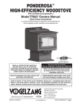
1
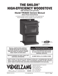
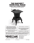
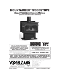
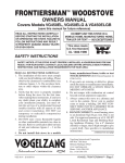
THE SHILOH™
High-Efficiency Woodstove
EPA Certified (4.22 grams/hr)
Model TR002B Owners Manual
(save this manual for future reference)
READ ALL INSTRUCTIONS CAREFULLY
BEFORE Installing OR OPERATING
This STOVE.
Failure to follow instructions
may result in property damage,
bodily injury, or even death.
This stove meets U.S. Test Standard:
Refer to markings on
STOVE labels for
additional information.
Do NOT use this STOVE in a
mobile home, Manufactured Home,
Tent or trailer – No Exceptions!
UL 1482-2006
NOTE: Installation MUST be
completed by a qualified
Heating Equipment Installer!
Vogelzang International Corporation
400 West 17th Street
Holland, Michigan 49423
www.vogelzang.com
Phone: 1-616-396-1911
Fax: 1-616-396-1971
VGZ-027B | 20110624.1
Vogelzang International Corp.
TR002B Shiloh™ | Page 1
SAFETY INSTRUCTIONS
Safety Notice: If this stove is not properly installed, a house/building fire
may result. For your safety, contact local building or fire officials about
permits, restrictions, and installation requirements for your area.
Read All Instructions carefully.
1. The installation of this stove must comply with
your local building code rulings. Please observe
the clearances to combustibles (see reference
figures 10–12). Do not place furniture or other
objects within the clearance area.
2. Verify that the stove is properly installed before
firing the stove for the first time. After reading these instructions, if you have any doubt
about your ability to complete your installation
properly, you must obtain the services of a
professional licensed installer familiar with all
aspects of safe and correct installation. DO NOT
use temporary or makeshift compromises
during installation.
3. DO NOT store wood, flammable liquids or other
combustible materials too close to the unit. Refer
to certification label on back of unit and reference
figures 10–12 in this manual.
4. Do not install this stove in a mobile
home, manufactured home, trailer or tent
NO EXCEPTIONS! (HUD Federal Standard:
24 CFR Ch.XX).
5.If any parts are missing or defective, please notify the dealer or manufacturer immediately. DO
NOT OPERATE A STOVE THAT IS MISSING
ANY PARTS!.
6. Do not operate with ash plug removed or tamper
with combustion air control(s) beyond normal
adjustment capacities.
7. Always connect this stove to a chimney and vent
to the outside. Never vent to another room or inside a building. DO NOT CONNECT THIS UNIT
TO A CHIMNEY FLUE SERVING ANOTHER
APPLIANCE.
8. Do NOT connect an aluminum Type B gas
vent to a wood burning stove. This is not safe.
Use a code-approved masonry chimney with flue
liner or a UL 103 HT Listed Residential Type and
Building Heating Appliance Chimney. Use a 6”
diameter chimney or larger, that is high enough
to give a good draft. (See specifics in installation
instructions).
9. Be sure that your chimney is safely constructed
and in good repair. Have the chimney inspected
by the fire department or a qualified inspector. Your
insurance company should be able to recommend
a qualified inspector.
10.Creosote or soot may build up in the chimney
connector and chimney and cause a house/
building fire. Inspect the chimney connector and
chimney twice monthly during the heating season and clean if necessary. (See Service Hints,
page 15).
11.In the event of a chimney fire, turn the air
control to closed position, leave the building and CALL THE FIRE DEPARTMENT
IMMEDIATELY! Have a clearly understood plan
on how to handle a chimney fire by contacting
your local fire authority for information on proper
procedures in the event of a chimney fire.
12.To prevent injury, do not allow anyone to use this
stove who is unfamiliar with the correct operation
of the stove.
13.Do not operate stove while under the influence of
drugs or alcohol.
14.Ashes should not be allowed to accumulate above
sides of ash drawer. Dispose of ashes in a metal
container with a tight fitting lid. Keep the closed
container on a noncombustible floor or on the
ground, well away from all combustible materials.
Keep the ashes in the closed container until all
cinders have thoroughly cooled. The ashes may
be buried in the ground or picked up by a refuse
collector.
15.The special paints used on your stove may
give off some smoke and an odor while
they are curing during the first 12 to 15 fires.
Additional smoke and odor may be emitted
from the light oils used in construction of the
fire box. This should disappear after a short
period of time and not occur again. Persons
with lung conditions or owners of susceptible domestic pets (such as birds) should take
prudent precautions. Open windows and
doors as needed to clear smoke and/or odor.
Paint discoloration will occur if the stove is
over fired.
16.This stove has a painted surface which
is durable but it will not stand rough handling
continued on next page
Page 2 | TR002B Shiloh™
www.vogelzang.com
VGZ-027B | 20110624.1
SAFETY INSTRUCTIONS continued…
or abuse. When installing your stove, use care
in handling. Clean with soap and warm water
when stove is not hot. Do not use any acids
or scouring soap, as these solvents wear and dull
the finish.
17. While stove is in operation all persons, especially
young children, should be alerted to the hazards
from high surface temperatures. Keep away from
a hot stove to avoid burns or clothing ignition.
18.If small children will be in the same room as the
stove during operation, provide a sturdy barrier
to keep them at a safe distance from the stove.
Never leave small children unsupervised when they are in the same room
as the stove.
19. The walls of the firebox may become slightly distorted after a period of use. A slight distortion will
not affect the operation of the stove.
20. Keep stove area clear and free from all
combustible materials, gasoline, and other flammable vapors and liquids.
21. To prevent burns always wear protective clothing,
leather hearth gloves and eye protection, while
tending the fire.
22. While in operation, keep the ash clean out cover in
place. Keep the feed door closed and secured at
all times except while tending the fire.
23. Do not over fire the stove. Over firing will
occur if the feed door or ash clean-out cover are
left open during operation. Such actions can result
in very dangerous operating conditions.
24. DO NOT ELEVATE FIRE! Build fire directly on the
bottom of the firebox. This stove has not been tested
with the use of grates, andirons, or other means of
elevating fire and should not be used.
25. All power cords and electrical appliances
and/or assemblies must be kept outside of the
clearance dimensions shown in this manual for
combustible materials.
26. For further information on using your stove
safely, obtain a copy of the National Fire
Protection Association (NFPA) publication, “Using
Coal and Wood Stoves Safely” NFPA No. HS-101978. The address of the NFPA is Batterymarch
Park, Quincy, MA 02269.
VGZ-027B | 20110624.1
NOTE: A professional, licensed heating and cooling contractor MUST
be consulted if you have questions
regarding the installation of this
solid fuel burning appliance.
Vogelzang International Corp.
TR002B Shiloh™ | Page 3
Table of Contents
Safety Precautions................................................................................ 2 – 3
Tools and Materials Required for Installation............................. 5
Assembly Instructions . ............................................................................. 5
Locating the Stove ....................................................................................... 7
Minimum Clearances .......................................................................... 7 – 8
Installation..................................................................................................... 8
Firebrick Assembly ...................................................................................... 9
Connector Pipe Installation.................................................................... 9
Chimney Sizing................................................................................................ 10
Chimney Connections.......................................................................... 10 –12
Operating Instructions
House Fire Hazards, Operating Precautions, Warnings....................... 13
Wood Types/Sizes..................................................................................... 13
Optimal Fuel Consumption..................................................................... 13
Starting a Fire, Adding Fuel.................................................................... 14
Service hints
Creosote Formation, Prevention, Removal . ......................................... 15
Chimney Draft ......................................................................................... 16
Glass Care & Replacement, Glass Gasket Replacement .................... 17
Glass Gasket Replacement .................................................................... 17
Parts – SHILOH™ ........................................................................................... 18
Parts – Glass Door (Glass Replacement)................................................. 19
Parts – Fire Brick . ...................................................................................... 19
Optional F-6 Blower Wiring Diagram................................................... 20
Floor Protector Calculations............................................................ 21
Chimney Connection Systems & Clearances.................................... 22
Page 4 | TR002B Shiloh™
www.vogelzang.com
VGZ-027B | 20110624.1
Assembly Instructions
NOTICE: Vogelzang International Corp. grants no warranty, stated or implied, for the installation or
maintenance of your wood stove and assumes no responsibility of any incidental or consequential damages.
Tools and Materials Required
for Installation
•
•
•
•
•
•
•
•
•
•
chimney. DO NOT REMOVE the ceramic blanket
or your stove will not operate properly.
tools
Pencil
6 foot Folding Rule or Tape Measure
Tin Snips
Drill: Hand or Electric
1/8” dia. Drill Bit (for sheet metal screws)
Screwdrivers (blade and Phillips type)
10mm Nut Driver or Ratchet with 10mm Socket
Safety Glasses
Gloves
11/16 Socket or Wrench
(NOTE: The following items are not included with your stove)
Flooring Protection: 36” x 48” as specified (see page 7)
Chimney Connection: 6” dia. minimum 24 MSG black or 26 MSG
blue steel straight stove pipe or elbow(s) as required.
1/2” Sheet Metal Screws
Chimney: Existing 6” Code-approved Lined Masonry Chimney or
6” Inside Dia. Listed Type HT manufactured chimney.
Furnace Cement (manufacturer recommends Rutland Code 78
or equivalent)
CAUTION: Stove is heavy. Make sure you
have adequate help and use proper
lifting techniques whenever moving
stove.
1. Uncrate the stove and remove all cardboard and
styrofoam packing materials and protective poly
bag. Remove pedestal base, sides, front, top, ashdrawer and ash drawer support from the carton.
(Save packing materials for further assembly.)
NOTICE: DO NOT remove ceramic blanket
material from inside stove pipe opening (Fig. 1).
This blanket provides an air seal on the side walls
of the stove to direct combustion gasses over the
secondary combustion tubes before exiting via the
DO NOT
REMOVE!
Figure 1 – DO NOT remove ceramic blanket from
inside stove pipe opening. This is NOT packing
material but an integral component of the stove
combustion system.
VGZ-027B | 20110624.1
Figure 2 – Pedestal
Assembly Hardware
sheet metal screws, 5/16˝
machine screw, lock
washer & hex nuts
Figure 3 –
Assemble
sides to base
2. Remove parts and hardware pack located inside
firebox.
3. Align the hole pattern of one of the pedestal sides
to the holes in the base and secure with four (4)
machine screws, lock washers and hex nuts. Assemble the opposite side to the base. (Note: Sides
are interchangeable)
Figure 4 –
Attach Pedestal
Front Frame to Sides.
(Note– front goes OVER
the side panels.)
4. Attach the pedestal front frame to the sides. The
pedestal front should go over (not inside of) the side
panels. Use three (3) self-tapping screws (provided
in the hardware pack) on each side to attach both
pedestal sides (#15) to the pedestal front (#17).
5. Position ash drawer support into assembled pedestal (Figure 5) and secure from rear with two (2)
machine screws, lockwashers and hex nuts. Tighten
all pedestal hardware.
6. Position the pedestal top with the large vent hole
positioned toward the front and attach with six (6)
Vogelzang International Corp.
continued on next page
TR002B Shiloh™ | Page 5
Assembly Instructions . . . continued
9. Tip the stove assembly upright.
10. Set the ash drawer inside the open box formed by
the pedestal front and sides.
11. For Optional Blower Assembly, note the position of
the blower opening in the rear of the stove.
12. Place blower gasket onto blower assembly so as
not to obstruct the air flow from the fan.
Figure 5 – Insert Ash Drawer Support.
Figure 8
Blower Option
13. Mount the blower assembly to the back of the stove
aligning the fan opening to the opening in the back
of the stove. Secure with four sheet metal screws.
14. After assembly, check to make sure fire brick are
properly positioned and ash cleanout cover is in
place.
Figure 6 – Attach Pedestal Top.
(Note– Position vent orifice towards front.)
machine screws, lock washers and hex nuts. (See
Figure 6)
7. Place flattened carton/styrofoam packing material
on floor and carefully tip the stove body onto it’s
back.
8. Align four (4) corner mounting studs with holes
in pedestal top (Figure 7). Secure with four (4)
hex nuts.
Figure 9 – Attach Optional Blower to Stove Body
Figure 7 – Attach Pedestal to Stove Body
Page 6 | TR002B Shiloh™
www.vogelzang.com
VGZ-027B | 20110624.1
Locating Stove
1. The stove must be placed on solid concrete, solid
masonry, or when installed on a combustible floor,
on a listed floor protector, such as Hy-C or Imperial
Model UL 3648BK or equivalent. Floor protector
must be 1/2” minimum thickness (“k” value = 0.84,
R value = 0.59, see page 21 for calculation formulas) non-combustible material or equivalent. The
base must extend at least 16” beyond the front of
the access door, 6” to the sides, and 12” beyond
the rear. It must extend under and 2 inches beyond
either side of the stove pipe if it is elbowed towards
a wall. (See figures 10 & 12 and consult local building codes and fire protection ordinances.)
.
CAUTION: (Fire Hazard) Carpeting and
other combustible material shall
not cover the floor protector. These
materials must remain outside of
combustible clearances, see fig. 5 – 7.
2. The stove must have its own flue. Do not connect this unit to a chimney flue serving other
appliances.
3. After observing the clearances to combustible materials (figures 10–12), locate your floor
protector accordingly (figure 10) and carefully place the stove in your selected location.
Install connector pipe, elbows, and thimble as
required, utilizing either a recently cleaned and
4.
5.
6.
7.
inspected 6” lined masonry chimney or a 6” i.d.
listed manufactured chimney.
Use round 6” dia., minimum 24 MSG black or 26
MSG blue steel stove pipe to connect the stove to
the chimney. Do not use galvanized stove pipe. Secure pipe sections with three (3) sheet metal screws
in each stove pipe and/or elbow joint to firmly hold
the pipe sections together. Do Not connect this
stove to any air distribution or duct system.
Recheck clearances from the stove, connector stove pipe, and cor ner clearances
using the illustrations in figures 10–12 and
your local building codes or fire protection ordinances.
NOTE: Any wall containing combustible
materials such as wooden studs, dr ywall or faced with drywall, brick or stone
must b e c o n s i d e r e d a c o m b u s t i b l e
surface.
Do Not install this stove in a mobile home,
Manufactured Home, Tent or trailer – NO
EXCEPTIONS! (HUD Federal Standard: 24 CFR Ch.xx)
The clearances provided are minimum
d i m e n s i o n s d e t e r m i n e d b y O M N I - Te s t
Laboratories, Inc. the manufacturer’s testing
agency. Installation of this stove must comply
with the latest edition of NFPA 211 for reduced
clearances and/or your local building code
continued on next page
TOP VIEW
COMBUSTIBLE CONSTRUCTION DEFINED IN ACCORDANCE WITH NFPA 211
DASHED LINES SHOW HORIZONTAL CHIMNEY CONNECTOR
AND ADDITIONAL FLOOR PROTECTOR REQUIRED BENEATH
AND EXTENDING 2” BEYOUND EACH SIDE
BACKWALL
35"
12"min
12"min.
46"
SIDEWALL
15"
min.
Vogelzang
TR002B
FLOOR
PROTECTOR
23"
18"
Use 36"x 48"
Standard Size
Floor Protector
16"min.
6"min.
Fig. 10 – Top View Minimum Clearance Dimensions from Combustible Surfaces
VGZ-027B | 20110624.1
Vogelzang International Corp.
TR002B Shiloh™ | Page 7
Locating Stove continued…
rulings. Use whichever minimum dimensions are
LARGEST.
8. T h i s s t o v e m e e t s U. S . Te s t S t a n d a r d :
UL 1482-2006.
CAUTION: Keep furnishings and other
combustible materials away from the
stove.
NOTE: Before firing woodstove slide
firebricks towards the rear so no
gaps remain between bricks.
Figure 11 – Minimum Side and Rear Clearance Dimensions from Combustible Surfaces
Figure 12 – Top View
Minimum Corner Clearances
from Combustible Surfaces
Page 8 | TR002B Shiloh™
www.vogelzang.com
VGZ-027B | 20110624.1
Firebrick Assembly
M
FF
FF
A
A
T
X
A
A
M
FF
FF
A
Z
MA
A
A
Y
Fire Brick Dimensions
A-Size: 9˝x4 1/2˝x1 1/4˝
FF-Size: 9˝x4 1/4˝x1 1/4˝
M-Size: 9˝x2 1/4˝x1 1/4˝
T-Size: 9˝x3 1/4˝x1 1/4˝
X-Size: 9˝x4 1/2˝x1 1/4˝**
Y-Size: 4 1/2˝x3˝x1 1/4˝
Z-Size: 3˝x2 1/2˝x1 1/4˝
** X Firebricks are notched
for air tube clearance
T
FF
Z
FF
Z
A
Fig.14b– Step 2, Side Firebrick Arrangement
Four (4) A-Size; Two (2) M-Size
X
X
T
Y
T
A
T
Y
G
A
F
M
CAUTION: NEVER OPERATE STOVE WITH
MISSING OR CRACKED FIRE BRICKS!
X
A
X
Firebrick extends the life of your stove and radiates
heat more evenly. Check to see that all firebricks are in
their correct positions and have not become misaligned
during shipping or assembly. If removed for ease of
locating stove, firebrick must be replaced before firing.
See diagrams, fig. 14a – 14c, for proper positioning.
Figure 14a – Step 1, Bottom Firebrick Arrangement
Two (2) FF-Size; Two (2) T-Size; Two (2) X-Size;
One (1) Y-Size; One (1) Z-Size
Fig.14c– Step 3, Back Firebrick Arrangement
Four (4) A-Size
connector Pipe Installation
1. The crimped end of the stovepipe fits inside the
stove flue collar. Secure with three sheet metal
screws. Install additional pipe and elbow with the
crimped end towards the stove. This will allow any
condensation in the flue to run back into the firebox. For side or rear wall venting, you must have
a minimum 24” vertical rise of pipe from the top of
stove to the horizontal pipe sections, see fig. 11).
2.Horizontal pipe runs must slope upwards
towards the chimney at least 1/4” per foot of horizontal run.
3. You must have at least 18 inches of clearance
between any horizontal piping and the ceiling.
4. The pipe cannot extend into the chimney flue
(figure 13).
5. Secure pipe/elbow sections with three (3) sheet
metal screws at each joint to make the piping
rigid.
6.It is recommended that no more than two (2)
90° bends be used in the stovepipe installation. The use of more than two 90° bends may
decrease the amount of draw and possibly
cause smoke spillage. Where possible, use only
corrugated (non adjustable) elbows. These
provide a better seal.
7. The connector pipe must not pass through an
attic or roof space, closet, or any concealed space,
floor, ceiling, wall or combustible construction. (See
Chimney Connector Systems & Clearances, page
22). A UL 103 HT Listed chimney must be used
from the first penetration of ceiling or wall to the
chimney cap.
CAUTION: Never use single wall connector pipe as a chimney - a house fire
could result.
CORRECTWRONGWRONG
NOTE: Connector pipe is NOT
I N CL U D E D . To purc h ase ,
Visit your local hardware,
home or building center. See
“Locating Stove” page 7 for
additional specifications.
Figure 13 – Stovepipe/Flue Connections
VGZ-027B | 20110624.1
Vogelzang International Corp.
TR002B Shiloh™ | Page 9
Chimney Sizing
Today’s solid fuel heating appliances are much
more efficient than those made in the past. Your heating appliance has been designed to provide the most
efficient transfer of heat possible from the least amount
of fuel.
Controlled combustion is the key to optimum heating performance. Controlled combustion requires a flow
of fresh air into the appliance, across the fuel and is
finally exhausted up the chimney.
Today’s high efficiency stoves transfer more heat
into the living area and less up the chimney. Exhaust
gases are typically at a lower temperature than traditional type stoves. With lower exhaust temperatures, it
is important that the chimney is correctly sized to the
stove. If the chimney diameter is too large, it will be difficult to raise the chimney flue temperature to provide for
adequate draft. This may result in a poor burn, smoke
spillage, and rapid creosote creation. A 6” diameter
chimney is best suited for this stove.
Your heating appliance must have a minimum of
a 6” diameter (152mm) chimney. Maximum chimney
diameter must not exceed 10” (254mm) or have a cross
sectional area greater than 85 sq. in. (550cm2.)
Proper draft for this heating appliance is minimum of
0.05 w.c. (water column measurement) and is required
to prevent back puffing, smoke spillage and prevent
safety hazards.
Chimney connections
The stove must be connected to either a lined masonry or manufactured metal chimney built and tested
to the specifications listed on the previous pages.
Chimneys perform two functions:
1). As a means of exhausting smoke and
flue gases which are the result of fuel combustion.
2). The chimney (only) provides “draft” which allows
oxygen to be continuously introduced into the
appliance, so that proper combustion is
possible. This stove relies on natural draft to
operate.
NOTICE: Always provide a source of fresh air
into the room where the stove is located. Failure
to do so may result in air starvation of other fuel
burning appliances and the possible development
of hazardous conditions, fire or death.
A stove does not create draft. Draft is provided
by the chimney. To achieve proper draft your chimney
must meet the four minimum height requirements
detailed in figures 16–18. If these minimum requirements are not met your stove will not operate
properly. A minimum of 0.05 w.c. (measured in water
column) is required for proper drafting to prevent back
puffing, smoke spillage, and to maximize performance.
(Gauges to measure draft are readily available at stove
stores and are economical to rent or purchase.)
Factors such as wind, barometric pressure, trees,
terrain and chimney temperature can have an adverse
effect on the draft. The manufacturer cannot be held
responsible for external factors leading to less than
optimal drafting.
Should you have a problem with inadequate draft,
you should contact a licensed heating and cooling contractor for assistance in solving the problem.
Page 10 | TR002B Shiloh™
IMPORTANT Installation Points
1. Size chimney flue to stove collar. This stove requires
a 6” diameter flue (see Chimney Sizing above).
2. Never connect this unit to a chimney serving
another appliance.
3. The chimney must meet all minimum height requirements.
4. Never use a chimney to ventilate a cellar or
basement.
5. C o n t a c t y o u r l o c a l b u i l d i n g a u t h o r i t y
for approved methods of installation and any
necessary permits and/or inspections.
Masonry Chimney
THIMBLE
6˝ ROUND
24 ga. BLACK
CONNECTOR
STOVEPIPE
COLLAR
CHIMNEY
FLUE
5/8" TILE
CHIMNEY
LINER
8˝ MIN.
LINER
BELOW
ENTRY
HOLE
MASONRY
CHIMNEY
Figure 15 - Masonry Chimney Connection
Before using an existing masonry chimney, ensure
it meets chimney sizing requirements above. Clean the
chimney, inspect the flue liner and make any repairs
needed to be sure it is safe to use. Make repairs before
attaching the stove. The connector stove pipe and fittings you will need to connect directly to a lined masonry
chimney are shown in figure 15.
If the connector stove pipe must go through a
combustible wall before entering the masonry chimney,
consult a qualified mason or chimney dealer. The instal-
www.vogelzang.com
VGZ-027B | 20110624.1
Chimney connections continued …
lation must conform to local building and fire codes and
latest edition of NFPA 211.
If there is a cleanout opening in the base of the
chimney, close it tightly.
Manufactured Chimney
Refer to chimney and chimney connector maker’s instructions for installation
and use.
Use only 6” diameter listed chimney UL 103 HT.
chimney made to this listing is High Temperature rated
to 2100 degrees Fahrenheit. Use chimney from only one
manufacturer. Never mix brands. Carefully follow the
chimney manufacturer’s stated requirements and clearances. Use the chimney manufacturer’s attic guards,
roof supports, flashing and fire stops when passing
through a ceiling. Use a listed thimble when passing
through a combustible wall. CAUTION: Never use
makeshift compromises during installation. Never
use a single-wall connection pipe as a chimney!
When using a pre-existing chimney, have it’s condition and installation inspected before using. Make sure
that the chimney meets all of the UL rating requirements
listed above. Be aware that not all manufactured chimney is of the UL 103 HT type.
NOTE: It is recommended that you contact a
licensed heating and cooling contractor (consult your
local yellow pages) for chimney installation.
Manufactured chimney with the proper required UL
listing is available from most home centers, hardware
stores, and HVAC supply stores.
If you have access to the internet, you may wish
to view chimney manufacturers’ information on-line.
See, www.duravent.com, www.selkirkinc.com, or
www.mtlfab.com.
Figure 16 - Chimney Construction
through Attic Space
Chimney Minimum Height Requirements:
(1) Overall Height – 15 ft. min.
(2) Height above roof – 3 ft. min.
(3) Height above slope – 2 ft. min. within 10 ft.
(4) Minimum rise before horiz. section – 24 in.
Notice: If minimum chimney requirements are not met, your stove will not
operate properly.
Venting to Existing Fireplace
In some instances, people desire to convert an existing fireplace for stove use. Usually, safe connection to
an existing masonry chimney requires more work than
using a prefabricated chimney. The existing fireplace
must be closed and sealed at the damper with hightemperature caulk, ceramic wool, or furnace cement.
Prior to installation, clean and inspect the existing flue
and smoke shelf. Installation should be designed so
the system can be dismantled for periodic cleaning and
inspection. Before conversion, make sure the existing
chimney is structurally sound, the chimney incorporates
a flue liner and make sure it is in good condition. (A flue
liner consists of clay tile that protects the brickwork of
a chimney. If a chimney does not have a liner, or it is
damaged, have it relined by a professional. Do Not use
a chimney that is unlined or damaged!) If you have
any question regarding the condition of the chimney,
continued on next page
VGZ-027B | 20110624.1
Figure 17 - Chimney Construction through Roof
Vogelzang International Corp.
TR002B Shiloh™ | Page 11
Chimney connections continued …
consult a qualified licensed contractor, qualified engineer, competent mason, certified Chimney Sweep,
or a knowledgeable inspector. Consult your insurance
company if you cannot find a qualified expert.
CAUTION: Not all fireplaces are suitable for conversion to a wood stove.
Check with a qualified expert.
Many prefabricated fireplaces are of the “zeroclearance fireplace” category. These consist of multi
layered metal construction. They are designed with
enough insulation and/or air cooling on the base, back
and sides so they can be safely installed in direct contact with combustible floors and walls. Although many
prefabricated fireplaces carry endorsements from nationally recognized organizations for use as fireplaces,
they have not been tested for connection to wood stove
heaters. Connecting a stove to such a device will void
the manufacturer’s warranty.
Steel-lined fireplaces are constructed with
1/4” firebox liner, an air chamber in connection with 8”
of masonry. These can be safely used with wood burning stoves. They contain all the essential components
of a fireplace, firebox, damper, throat, smoke shelf,
and smoke chamber. Many look identical to masonry
fireplaces and should be checked carefully before connecting a stove to them.
Venting a stove directly into a fireplace does not
meet code and should not be attempted. (This constitutes connection to another appliance - the fireplace.)
Combustion products will be deposited and build up in
the firebox or fireplace. The stove warranty will be void
with such an installation. Do not create a hazard in your
home by connecting in this manner.
Fireplace Installation
NOTE: Do NOT attempt to route the chimney connector pipe through the throat of
the fireplace. Directly connecting the stovepipe
into the existing masonry chimney (figure 19 “Type A”
fireplace conversion) of the fireplace is the only approved method of installation. This is a complicated
and involved process and to insure safety should only
by done by a qualified installer.
1. An entry hole must be cut through the masonry and
tile liner with minimal damage to the liner. At least 8”
of liner must remain below the entry position. When
locating the stove and stovepipe, all minimum clearances must be observed from combustible surfaces
including mantels, combustible trim work, ceilings
and walls. Positioning the center of the stove pipe
entry into the chimney 24” below the ceiling should
insure proper clearance for a 6” stovepipe.
2.Install a metal or fire clay (5/8” minimum thickness)
thimble. Make sure the thimble is flush with the inner
Page 12 | TR002B Shiloh™
Figure 18 - Chimney Connection to Firebox
through Masonry Wall
surface of the chimney liner and does not protrude
into the flue (see figure 13 on page 9).
3. Secure the thimble with refractory mortar. The
thimble should be surrounded by 8” of solid unit
masonry brickwork or 24” of stone.
4.Install the stovepipe into the thimble as far as possible without extending past the flue lining (see
figures 13 & 15 on pages 9 & 10).
5. A small airspace (about 1/2”) should remain between
the stovepipe and thimble to allow for expansion of
the pipe. Seal this airspace with high-temperature
caulking or ceramic wool.
6. Secure and seal the damper in the closed position
using high-temp caulking, ceramic wool, or furnace
cement. Also check to see if the chimney has a
cleanout. If it does, make sure it is closed and sealed
as well. A leaky cleanout will greatly reduce draft
efficiency.
If you have any questions regarding venting your
stove, contact the manufacturer or contact the National
Fire Protection Association (NFPA) and request the latest editions of NFPA Standard 211 and NFPA Standard
908. Their address is:
Battery March Park, Quincy, MA 02269.
Figure 19 - Fireplace Conversion
www.vogelzang.com
VGZ-027B | 20110624.1
Operating Instructions
CAUTION: HOUSE FIRE HAZARDS
This stove is designed to burn
WOOD FUEL ONLY!
• Do not store wood on floor protector, underneath stovepipe or anywhere within minimum clearances from
combustible surfaces specified for
this stove.
Hardwood, 15” to 17” should be split and air dried
(seasoned), for 6 months to obtain maximum burning
efficiency. Wood should be stored in a dry, well ventilated area.
•Over firing may cause a house fire.
You are over firing If a unit or chimney
connector glows Red.
NOTICE: Use solid wood materials only.
Do Not burn garbage or flammable
fluids. Do Not Use Coal This stove is not
designed to accommodate the air flow
(draft) necessary to properly burn
coal or coal products. Do not elevate
fire or use grates or andirons. Build
fire directly on bottom of firebox.
Operating Safety Precautions
1. Never over fire this stove by building excessively hot fires as a house/
building fire may result.You are over
firing the stove if unit or stovepipe
begins to glow or turn red.
2. Never build extremely large fires
in this type of stove as damage to
the stove or smoke leakage may
result
3. On models with glass door, do not
build fire too close to glass.
4. Unit is HOT while in operation. Keep
children, clothing, and Furniture
away. Contact may cause skin burns.
Do not touch the stove after firing
until it has cooled.
5. Provide air into the room for proper combustion.
6. Inspect stovepipe every 60 days.
Replace immediately if stovepipe is
rusting or leaking smoke into the
room.
WARNING: Explosion Hazard
• Never use chemicals, gasoline,
gasoline-type lantern fuel, kerosene,
charcoal lighter fluid, or similar
flammable liquids to start or “freshen-up” a fire in the stove.
• K eep a ll fl a mm a ble li q uids ,
especially gasoline, out of the
vicinity of the heater — whether in use
or in storage.
OPTIMAL FUEL CONSUMPTION
This stove is designed to get the most efficient
transfer of heat energy from the wood fuel and radiate
it into your living environment. The fire box introduces
combustion air through three sources. (1) Immediately
beneath the door opening below the window is a Lower
Primary Air Orifice (LPAO). (2) The door air inlet control brings air into the firebox and controls the rate of
burn (and the amount of heat the stove radiates). (3)
The secondary air tubes at the top of the firebox are
designed to ignite the combustion gases (smoke) given
off by the burning wood and increases the efficiency of
the stove and reduces chimney emissions.
Smoke given off by burning fuel consists of very
small organic liquid droplets. If these droplets condense,
they form a sticky tar-like substance called creosote.
When operated properly, this stove is designed to burn
these droplets. Burning these droplets releases heat
that would otherwise be lost up the chimney as smoke.
Following the instructions below will help you operate
your stove properly to maximize the stove’s performance. Actual performance is dependent on chimney
height, weather, log size, wood species and moisture
content. Some experimentation will initially be required
to find that “sweet spot” where your stove performs best.
The following will give you a starting point to find your
optimum settings.
When first loading fuel set the door air inlet control
at the wide open position for at least 15–20 minutes.
When the stove is working properly you should be able
to observe secondary combustion flames above the fuel
pieces in front of the secondary air tubes at the top of
the firebox. These secondary flames should continue to
burn after the primary air inlet is reset from wide open
to the desired operating setting. If the flames do not
continued on next page
VGZ-027B | 20110624.1
Vogelzang International Corp.
TR002B Shiloh™ | Page 13
Operating Instructions continued . . .
continue to burn, open the air control to re-establish the
secondary flames then slowly reset the air control to the
desired setting. Initially it may take several attempts to
figure your stove out. But once you find the operating
“sweet spot” and the correct mix of procedures to get
there, only minor adjustments will be necessary.
The best indicator of a properly operating stove is
to look for smoke coming out of the chimney. You may
see steam emissions that will quickly dissipate. Smoke
will thin but continue to drift without totally disappearing.
If you do detect smoke emissions, open the air control
a little bit, let the stove adjust for 10–15 minutes and
re-check your chimney. Remember – visible smoke
represents lost heat.
when air is allowed to circulate to all areas of the
firebox. TIP: If ash or coals remain in the stove,
make sure to clear them away from the Lower Primary Air Orifice (LPAO) and rake a slight (1-to-2
inch wide) trough down the center of the coal bed
from front to back prior to loading the fuel.
7.Once fuel has been loaded, close the door and
leave the air inlet control fully open until fire is well
established (at least 15–20 minutes) being careful
not to over fire (if any of the exterior parts of the
stove or chimney connections begin to glow you
are over firing the stove).
8. Re-adjust the air inlet control to desired burn rate.
For “low “ setting slide control all the way to left, for
“high” slide all the way to right. (If excessive smoke
fills the firebox, open air inlet control slightly until
flames resume and wood is sufficiently ignited.)
The basic rule of thumb is “closed = low,” “half way
open = medium” and “fully open = high.”
NOTICE - INITIAL BURNS to Cure PAINT
Because of the high operating
temperatures, this stove uses
a special high-temp paint which
requires a series of burns to
cure the paint for durability and Adding Fuel
If the coal bed is not hot and glowing, rake the coals
a lifetime of service.
Proper curing of the high-temp paint
requires a series of three initial burns. The stove
should be allowed to cool off between each burn.
The first two burns should be small fires and low
temperatures (250 degrees F) for a duration of
20 minutes each. The third fire should be at a
medium-high temperature (500 F to 700 F) for twenty
minutes. Provide adequate cross ventilation to clear any
smoke or odor caused by initial firings.
STARTING a Fire
1. Set air inlet control to fully open position. (slide to
right) NOTE: Open/High=right Cosed/Low=left
2.Open the feed door and place several wads of
crushed paper in the firebox.
3. Cover the paper with a generous amount of kindling in a teepee fashion and a few small pieces of
wood.
4.Ignite the paper and leave the door open slightly.
DO NOT LEAVE STOVE UNATTENDED WITH
DOOR OPEN!
5. Add large pieces of wood as the fire progresses
being careful not to overload. (Do not fill firebox
beyond firebrick area.) An ideal coal bed of 1 – 2”
should be established to achieve optimum performance.
6. This unit is designed to function most effectively
Page 14 | TR002B Shiloh™
to the front of the stove, close the door and adjust the air
inlet control to the wide open position. Let the coals reheat for 10–15 minutes. When hot and glowing, spread
them out and place your next fuel load into the stove
(make sure no coals or ashes block the LPAO). Leave
the door air inlet control in the wide open position for
15–20 minutes.
Fuel load size can vary but should be kept 1–2
inches below the secondary air tubes. Also position the
fuel to leave space so the air from the inlet can work
down between the pieces of fuel. This reduces the time
it takes for new fuel to burn properly.
1. When refueling, adjust air inlet control to the fully
open position. When fire brightens, slowly and
carefully open the door. This procedure will prevent
gases from igniting causing smoke and flame spillage.
2. When adding fuel, be careful not to hit or bump
the ceramic baffle board located at the top of the
firebox.
3. Add fuel being careful not to overload or over fire
the stove.
4. When adding fuel be careful not to smother the
fire. Do not build fires against glass and make sure
the coal bed does not obstruct the air inlet. Do not
add fuel to such a height or in such manner that it
creates a hazard when opening the door.
5. Close the feed door and secure tightly.
www.vogelzang.com
continued on next page
VGZ-027B | 20110624.1
Service Hints
6. Adjust the air inlet control as described above.
7. Empty ashes regularly. Do not allow ashes
to pile up (see Safety Instructions #14 on
page 2.)
8. Properly dispose of hot ashes (see Safety
Instructions, item #14 on page 2.)
9. Do not over fire the stove (over firing is when
any par t of the stove exterior or chimney
connections glow).
CAUTION: DO NOT OVER FIRE appliance.
You are over firing if the chimney
connectors or stove glows red. Close
the door and shut damper immediately
to reduce the air supply and slow
down the fire.
CAUTION: Slow burning fires and
extended use may cause excessive
creosote buildup. Ignition of creosote or over firing may cause a
chimney fire. Chimney fires burn
extremely h ot and may i g nite
surrounding materials. In case of a
chimney fire call the fire department
immediately.
CREOSOTE – Formation and Removal
CAUTION: RISK OF FIRE When wood is burned
slowly, it produces tar and other organic vapors
which combine with expelled moisture to form
creosote. The creosote vapors condense in the
relatively cool chimney flue of a slow-burning
fire and can accumulate on the flue lining. If
ignited, this creates an extremely hot fire in the
chimney which may ignite surrounding materials resulting in a building fire.
The chimney connector and chimney should be
inspected (at least) twice a month during the heating
season to determine if a creosote buildup has occurred.
If it has, it should be removed. Failure to remove creosote may result in ignition and may cause a house/
building fire. Creosote may be removed using a chimney
brush or other commonly available materials from your
local hardware retailer.
Chimney fires burn very hot. If the unit or chimney
connector should glow red, reduce the fire by closing the inlet air control and immediately call the fire
department.
CAUTION: A chimney fire may cause ignition of wall studs or rafters which
were assumed to be a safe distance
from the chimney. If a chimney fire
has occurred, have your chimney inspected by a qualified Expert before
using again.
A fire in the firebox may be smothered by pouring
a large quantity of coarse salt, baking soda, or cool
ashes on top of the fire.
Service Hints
Preventing Creosote Buildup
1. Creosote will inevitably form in your chimney and
connector pipe. Following these steps will help
reduce the rate of build up.
2. BURN ONLY SEASONED WOOD that has dried
for at least one year.
3. Burn hardwood rather than softwood. Hardwood
is denser or heavier wood and burns hotter.
4. Do not attempt to burn (or mix in) green or wet
wood. The use of green or wet wood will cause a
rapid build up of creosote. Wood that hisses, sizzles
and blackens without igniting in five minutes must
be considered too wet to burn.
5. Do not attempt to extend the burn time by using
wet wood. Not only does burning wet wood rapidly
build up creosote, but it reduces the heat output by
up to 25 percent.
6. Burn the stove with the air inlet control wide open
for 10-25 minutes every time fresh wood is loaded
into the stove. Do not load more than ¼ to ½ of the
fuel capacity at one time. Loading too much wood
at once will cause excessive smoke which contains
creosote. Mature fires or coals produce very little
creosote-producing smoke.
7. Burn with the control open for several minutes at
numerous intervals throughout the day, being careful not to over fire the unit. Following this process
will help to warm the chimney and reduce the
amount of creosote forming condensation within
the chimney.
8. Establish a routine for the handling of fuel, firing,
and operating the stove. Check daily for creosote
build up until experience shows how often you need
to clean for safe operation. Be aware that the hotter
the fire, the less creosote is deposited and weekly
cleanings may be necessary in mild weather even
though monthly cleanings may be enough in the
colder months.
continued on next page
VGZ-027B | 20110624.1
Vogelzang International Corp.
TR002B Shiloh™ | Page 15
Service Hints continued . . .
WARNING: In case of chimney fire
(1) Close air inlet control (2) Get out
of the house (3) Call the fire department.
Chimney Draft
The chimney is critical to the proper operation of
the stove. It is the chimney that creates draft; THE
STOVE DOES NOT AND CANNOT CREATE DRAFT.
The chimney provides two vital functions for proper
stove operation. First, it is the passage to exhaust
smoke and hot gases created in the combustion process. Secondly, it supplies the draft (or pressure) to
bring oxygen to the fire to sustain combustion. Draft is
the natural movement of air or gases through a chimney.
Chimney draft comes from the natural tendency for
hot (less dense) air to rise. As the hot air rises within
the chimney it creates a lower pressure at the bottom
of the chimney to which the stove is connected. The
higher pressure air outside the stove then rushes into
the stove where the lower air pressure level exists, thus
bringing oxygen to the fire. This constant flow of air is
referred to as the draft. Many factors or combination
of factors can act together to build or impede the draft.
Without the correct amount of draft, the stove will not
operate properly.
If there is excessive draft, an unsafe condition will
arise with too much air being drawn into the stove and
creating an excessively hot fire. This could cause over
firing which runs the risk of igniting structural elements
around the stove and chimney.
The most common experience is that of insufficient
draft. Under insufficient draft conditions, the fire will be
starved for oxygen, improper or incomplete combustion
occurs resulting in smoke spillage into the area around
the stove. A fire that is starved for oxygen will not burn
well. Such a fire will produce excessive smoke that will
cool and condense in the chimney creating creosote.
Excessive amounts of creosote buildup can ignite
causing a chimney fire with the possibility of structural
elements igniting as well.
Correct any draft related issues before using the
stove. The following are some possible causes of
insufficient draft. Please note that one or more factors
may play a role in a draft issue and certain factors may
change over time as conditions vary.
1. Atmospheric Pressure and Air Supply
Atmospheric pressure that affects the draft may occur from outside the structure, inside the structure,
or both. High pressure weather (clear and cold)
usually produces a better chimney draft than low
Page 16 | TR002B Shiloh™
pressure (overcast and damp) conditions. Negative
pressure can be created inside a home by appliances that expel air from within such as bathroom
vents, range hoods, clothes dryers, and forced air
furnaces. Do not allow such appliances to overcome the natural draft. Note that newer homes
tend to be built more tightly allowing less make up
air to seep freely in. Negative pressure may be
overcome by opening a nearby door or window. In
extreme conditions of negative draft, the airflow in
the chimney will reverse direction. This is known
as “down drafting.”
2. Environmental Factors
Wind or air deflecting off external objects such
as the roof, neighboring structures, trees, or hills.
These can cause a pressure change in the air surrounding the chimney.
3. Chimney Temperature
The temperature of the chimney is an important
factor in how well it drafts. Warm chimneys draft
better than cold chimneys. This is based upon the
principle that hot air rises while cold air sinks. Hot
gases going up a cold chimney will cool rapidly.
Warm the chimney by allowing a hot fire to burn for
the first fifteen to thirty minutes after starting the fire.
Be careful not to over fire the stove. If any part of
the stove or chimney starts to glow, you are over
firing the stove. Masonry chimneys will take longer
to warm than manufactured chimneys on account of
their greater structural mass. Chimneys that have a
flue diameter larger than the stove outlet take more
heat to warm, thus resulting in a faster cooling of
the hot gases needed to build or maintain draft.
4. Chimney Installation and Maintenance
Confirm that all four minimum chimney height
requirements listed in the Chimney Connection
section of the manual have been met. The physics
that link chimney height with draft creation are vital
to the proper operation of the stove. Failure to meet
each of these minimum requirements will have an
adverse affect on draft. Avoid long horizontal runs
or multiple elbows. Use stove cement to seal joints
in the connector pipe section. Regularly clean the
chimney, connector pipe, rain cap, and spark arrestor screen. Creosote build up can reduce the
chimney draw and possibly create a chimney fire.
5. Temporarily out of Operation
After the fire has burned out, open the air control
to its fully open position. This will allow warm room
air to enter the chimney and keep it as warm as
possible until the stove is used again.
www.vogelzang.com
VGZ-027B | 20110624.1
Service Hints continued . . .
For assistance involving chimney draft issues, contact a knowledgeable licensed heating and cooling
contractor in your area. For questions regarding
manufactured chimney, contact the manufacturer
of the chimney.
NOTE: A draft reading of 0.05 to 0.06 w.c.
(Water column) is required for proper
burning of this stove.
Glass Care
The following usage and safety tips should be
observed:
1.Inspect the glass regularly for cracks and breaks.
If you detect a crack or break, extinguish the fire
immediately and contact the manufacturer for a
replacement.
2. Do not slam the door or otherwise impact the glass.
When closing doors, make sure that logs or other
objects do not protrude to impact the glass.
3. Do not build fires against (or that might fall against)
the glass.
4. Do not clean the glass with materials that may
scratch (or otherwise damage) the glass. Scratches
on the glass can develop into cracks or breaks during operation.
5. Never attempt to clean the glass while the unit is
hot. If deposits are not very heavy, normal glass
cleaners are adequate using a soft, non-abrasive
cleaning pad. Heavier deposits may be removed
with oven cleaners.
6. Never put substances which can ignite explosively
in the unit. Even small explosions in confined areas
can blow out the glass.
Glass Replacement
Caution: Replace glass ONLY with 5mm
High Temperature ceramic glass of the
proper size. Do not use tempered glass
or double thickness window glass!
Gasket and Glass cleaning products are available
at local retail home centers. Manufacturers of cleaning
products include, A.W. Perkins Co. (www.awperkins.
com) or Rutland Products (www.rutland.com).
After extensive use, the gasket material which
provides glass and door seal may lose it’s resiliency
and will need to be replaced. Inspect glass and door
gaskets periodically to ensure proper seal; if gaskets
become frayed or worn, replace immediately.
Glass Replacement Procedure:
1. Ensure appliance is not in operation and is thoroughly cooled.
2. Remove screws and glass clips. (See parts list and
diagram.)
3.Lift glass out from door.
4. Remove old gasket and clean glass.
5. Replace new gasket starting at the bottom of glass
working along edges, being sure to center gasket
channel on glass.
6. Trim to length and butt ends together.
7. Replace glass into door, being sure not to overtighten screws and clips.
Door Gasket Replacement
Procedure:
1. Ensure appliance is not in operation and is thoroughly cooled.
2. Remove old door gasket and clean channel.
3. Using an approved, high temperature gasket cement, apply a thin coat in bottom of channel.
4. Starting at hinge side of door, work gasket into
channel around door unit, end butt and trim to
length.
5. Close door and allow three to four hours for cement
to set before firing appliance.
VGZ-027B | 20110624.1
Vogelzang International Corp.
TR002B Shiloh™ | Page 17
Ordering Parts - TRoo2B SHILOH™ stove
When ordering missing or replacement parts, always give the Model Number of the stove,
Part Number, and Part Description. Use the illustrations and part lists provided to identify parts.
Contact us at 616-396-1911 to order parts.
1
2
5, 6
7
8, 9, 10
3
4
F-6S
F-6
NOTE: F6 Blower is
Optional Equipment
11 Fire Brick
15
F-6G
16
12
33
33
34
14
29
31
32
30
35
Part No. DescriptionQty.
Part No. DescriptionQty.
2B-01 Ceramic Fiber Pad . . . . . . . . . . . . . . . . . . . . . . 1
2B-02 C-Cast Fiber Board (9.3˝ x 11˝ x 0.5˝) . . . . . . . 2
2B-03 Air Tube, Middle & Rear . . . . . . . . . . . . . . . . . . 1
2B-04 Air Tube, Front . . . . . . . . . . . . . . . . . . . . . . . . . . 1
2B-05 Retainer Clips, Air Tube . . . . . . . . . . . . . . . . . . 3
2B-06 Bolt, Retainer Clip . . . . . . . . . . . . . . . . . . . . . . . 3
2B-07 Nickle Trim, Top Plate . . . . . . . . . . . . . . . . . . . . 1
2B-08Handle, Slide Draft Spring . . . . . . . . . . . . . . . . 1
2B-09 Slide Draft . . . . . . . . . . . . . . . . . . . . . . . . . . . . . 1
2B-10 Cover, Slide Draft . . . . . . . . . . . . . . . . . . . . . . . 1
2B-11 Fire Brick: See Chart on next page
2B-12 Nickle Trim, Hearth . . . . . . . . . . . . . . . . . . . . . . 1
2B-13
2B-14 Nuts (9/16” pedestal/stove attachment) . . . . . . 4
2B-15 Door Assembly (complete) . . . . . . . . . . . . . . 1
2B-16
Handle Assembly (complete) . . . . . . . . . . . 1
2B-17
Hinge Pin . . . . . . . . . . . . . . . . . . . . . . . . . . 1
2B-18
Door Frame . . . . . . . . . . . . . . . . . . . . . . . . . 1
2B-19
Door Glass . . . . . . . . . . . . . . . . . . . . . . . . . 1
2B-20
WG01Glass Gasket, 3/8˝ Fiberglass . . . . . . 1
2B-21
2B-22
2B-23
2B-24
Page 18 | TR002B Shiloh™
Retainer, Glass . . . . . . . . . . . . . . . . . . . . . . 5
Retainer, Handle Side Glass . . . . . . . . . . . 1
Screws, Glass Retainer . . . . . . . . . . . . . . . 8
GK34 Door Gasket, 3/8˝ Fiberglass . . . . . . 1
2B-29 Ash Cleanout Cover . . . . . . . . . . . . . . . . . . . . . 1
2B-30 Pedestal Base . . . . . . . . . . . . . . . . . . . . . . . . . . 1
2B-31 Pedestal Side . . . . . . . . . . . . . . . . . . . . . . . . . . 2
2B-32 Pedestal Front . . . . . . . . . . . . . . . . . . . . . . . . . . 1
2B-33 Pedestal Top . . . . . . . . . . . . . . . . . . . . . . . . . . . 1
2B-34 Pedestal Drawer Support . . . . . . . . . . . . . . . . . 1
2B-35 Ash Drawer . . . . . . . . . . . . . . . . . . . . . . . . . . . 1
2B-HPHardware Pack (not shown) . . . . . . . . . . . . . . . 1
Blower Option (NOT included as standard equipment)
F-6Optional Blower Assembly . . . . . . . . . . . . . . . . 1
F-6G Gasket, Ceramic Blower . . . . . . . . . . . . . . . . . . 1
F-6S Screws, Blower Mounting . . . . . . . . . . . . . . . . . 4
www.vogelzang.com
VGZ-027B | 20110624.1
Parts - TR002B Shiloh™ High-Efficiency stove
When ordering missing or replacement parts, always give the Model Number of the stove,
Part Number, and Part Description. Use the illustrations and part lists provided to identify parts.
Contact us at 616-396-1911 to order parts.
17
23
22
19
18
20
21
24
art No. DescriptionQty.
P
2B-15 Door Assembly (complete) . . . . . . . . . . . . . . 1
2B-16
Handle Assembly (complete) . . . . . . . . . . . 1
2B-17
Hinge Pin . . . . . . . . . . . . . . . . . . . . . . . . . . 1
2B-18
Door Frame . . . . . . . . . . . . . . . . . . . . . . . . . 1
2B-19
Door Glass . . . . . . . . . . . . . . . . . . . . . . . . . 1
2B-20
WG01Glass Gasket, 3/8˝ Fiberglass . . . . . . 1
2B-21
Retainer, Glass . . . . . . . . . . . . . . . . . . . . . . 5
2B-22
Retainer, Handle Side Glass . . . . . . . . . . . 1
2B-23
Screws, Glass Retainer . . . . . . . . . . . . . . . 8
2B-24
GK34 Door Gasket, 3/8˝ Fiberglass . . . . . . 1
M
Fire Brick: Sides
FF
Z
A
FF
Fire Brick: Back
X
A
Z
A
FF
Y
T
A
A
X
A
M
FF
FF
VGZ-027B | 20110624.1
MA
A
A
T
FF
X
Z
T
Y
T
X
Fire Brick: Bottom
A
T
Y
A
G
M
F
2B-11 Fire Brick
2B-11A Fire Brick, A-size........................................ 8
2B-11FF Fire Brick, FF-size...................................... 2
2B-11M Fire Brick, M-size....................................... 2
2B-11X Fire Brick, X-size........................................ 2
2B-11T Fire Brick, T-size......................................... 2
2B-11Y Fire Brick, Y-size......................................... 1
2B-11Z Fire Brick, Z-size........................................ 1
X
Part No. DescriptionQty.
A
Vogelzang International Corp.
TR002B Shiloh™ | Page 19
Wiring Diagram - Model F-6 Blower Option
Page 20 | TR002B Shiloh™
www.vogelzang.com
VGZ-027B | 20110624.1
Floor Protector Material Calculations
This stove has been tested for and must be installed on a floor protector with the proper Thermal Resistance or R-value
as stated in the installation instructions on page 7, “Locating Stove” step 1, of this manual. If the floor protector materials
listed in the instructions are not available, materials with an equivalent R-value may be substituted.
Alternate materials may be rated with C-factor (Thermal Conductance) or k-factor (Thermal Conductivity) ratings
which must be converted to R-value to determine if the alternate material meets the tested requirements. The following
instructions provide the proper information and formulas for conversion to R-value.
To determine if alternate materials are acceptable follow this sequence.
1. Convert material specifications to R-value:
a. R-value given — no conversion necessary
b. k-factor is given with a required thickness (T) in inches:
R = 1/k x T
c. C-factor is given: R = 1/C
2. Determine the R-value of proposed alternate floor protector:
a. Use formulas in step 1 above to calculate R-value of proposed material(s).
b. For multiple layers, add R-values of each layer to determine overall R-value.
3. If the overall R-value of the floor protector system is equal to or greater than the floor protector specifications given,
the alternate is acceptable.
Definitions:
Thermal conductance(C) = BTU
=
(hr)(ft2)(°F)
W
(m2)(°K)
Thermal conductivity (k) =
(Btu)(inch)
=
2
(hr)(ft )(°F)
W
=
(m)(°K)
Thermal resistance (R) =
(ft2)(hr)(°F)
=
Btu
(m2)(°K)
W
Example:
The specs of floor protector material should be 3/4-inch thick material with a k-factor of 0.84.
The proposed alternative material is 4” brick with a C-factor of 1.25 over 1/8-inch mineral board
with a k-factor of 0.29.
Step 1: Convert specs to R-value.
R = 1/k x T = 1/0.84 x 0.75 = 0.893 System must have a R-value of 0.893 = Rspecs
Step 2: Calculate R-value of individual components
4” Brick with C-factor = 1.25. R = 1/C = 1/1.25 = 0.80 = Rbrick
1/8-inch (0.125”) mineral board with k-factor = 0.29. R = 1/0.29 x 0.125 = 0.431 = Rmin.brd.
Step 3: Add R-values of components to get total R-value of system
Rbrick + Rmin.brd = 0.80 + 0.431 = 1.231 = Rsystem
Step 4: Compare Rsystem to Rspecs
Rsystem = 1.231 is larger than Rspecs of 0.893. System R-value exceeds
specifications and therefore is an acceptable alternative.
VGZ-027B | 20110624.1
Vogelzang International Corp.
Btu
(hr)(ft)(°F)
the required
TR002B Shiloh™ | Page 21
Chimney Connector Systems & Clearances
A. Brick Masonry
Minimum 3.5˝/89mm thick brick masonry all framed into
combustible wall with a minimum of 12˝/305mm brick
separation from clay liner to combustibles. The fireclay
liner shall run from outer surface of brick wall to, but not
beyond, the inner surface of chimney flue liner and shall
be firmly cemented in place.
B. Insulated Sleeve
Solid-insulated, listed factory-built chimney length of the
same inside diameter as the chimney connector and
having 1˝/25.4cm or more of insulation with a minimum
9˝/229mm air space between the outer wall of the chimney length and combustibles.
C. Ventilated Thimble
Sheet steel chimney connector, minimum 24 gauge in
thickness, with a ventilated thimble, minimum 24 gauge in
thickness, having two 1˝/25.4mm air channels, separated
from combustibles by a minimum of 6˝/152mm of glass
fiber insulation. Opening shall be covered, and thimble
supported with a sheet steel support, minimum 24 gauge
in thickness.
D. Chimney Section Pass-through
Page 22 | TR002B Shiloh™
Solid insulated, listed factory-built chimney length with an
inside diameter 2˝/51mm larger than the chimney connector and having 1˝/25.4mm or more of insulation, serving
as a pass-through for a single wall sheet steel chimney
connector of minimum 24 gauge thickness, with a minimum 2˝/51mm air space between the outer wall of chimney section and combustibles. Minimum length of chimney section shall be 12˝/305mm chimney section spaced
1˝/25.4mm away from connector using sheet steel support plates on both ends of chimney section. Opening
shall be covered, and chimney section supported on both
sides with sheet steel support securely fastened to wall
surfaces of minimum 24 gauge thickness. Fasteners
used to secure chimney section shall not penetrate
chimney flue liner.
www.vogelzang.com
VGZ-027B | 20110624.1
VGZ-027B | 20110624.1
Vogelzang International Corp.
TR002B Shiloh™ | Page 23
This Vogelzang heating appliance is safe when installed properly and will provide you with years of service.
However, always exercise good judgement when you are using this stove. You are dealing with FIRE! Fire is
inherently dangerous and must be treated with respect. Stay warm and in good health!
Respectfully yours,
Steve Vogelzang
Proprietor
Do NOT use this stove in a
mobile home, Manufactured Home,
trailer or Tent — NO EXCEPTIONS!
Company Testimony:
“For God so loved the world that he gave his only begotten Son, that whoever
believes in Him shall not perish but have eternal life”
John 3:16
MADE IN CHINA
Vogelzang International Corporation
400 West 17th Street
Holland, Michigan 49423
www.vogelzang.com
Phone: 1-616-396-1911
Fax: 1-616-396-1971
Page 24 | TR002B Shiloh™
www.vogelzang.com
VGZ-027B | 20110624.1