1
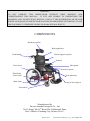
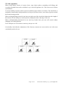
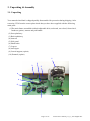
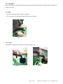
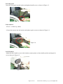
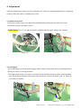
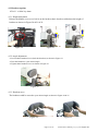
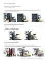
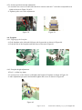
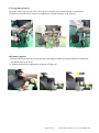
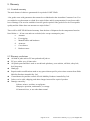
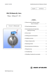
C550 Recline and Tilt Wheelchair Owner’s Manual Pride Mobility Products Australia Pty. Ltd. 20-24 Apollo Drive, Hallam, Victoria, Australia 3803 Page 1 of 27 C550 Owner's manual_17_11_2011 English.doc WARNING! DO NOT OPERATE THIS WHEELCHAIR WITHOUT FIRST READING AND UNDERSTANDING THIS MANUAL. IF YOU ARE UNABLE TO UNDERSTAND THE WARNINGS AND INSTRUCTIONS WHOLLY, CONTACT THE DISTRIBUTOR OR DEALER WHERE YOUR MANUAL WHEELCHAIR WAS PURCHASED BEFORE ATTEMPTING TO USE THIS EQUIPMENT. OTHERWISE INJURY OR DAMANGE MAY RESULT. COMPONENTS Headrest (option) Back upholstery Push handle Lateral support (option) Armrest Rear wheel Skirt guard Pommel (option) Hand brake (wheel lock) Seat upholstery Main frame Swing in & out legrest Front wheel Manufactured by Taiwan Armada Enterprise Co., Ltd. No.12 Kung-Yeh 14th Road, Da-Li Industrial Zone, Da-Li District, Taichung City, Taiwan, R.O.C. Page 2 of 27 C550 Owner's manual_17_11_2011 English.doc (Customer Service Support) Please contact nearest distributor (dealer) for after service. Before calling: Please fill in the following information. The details below will help us assist you faster and ensure we provide you with the best advice concerning your wheelchair. Batch Number .................................. Model ................................................ Date of purchase ............................... (Notice): The information contained in this User‟s Guide is subject to change without notice. No part of this document may be photocopied, reproduced, transmitted, transcribed, stored in a retrieval system or translated to another language or computer language, in any form or by any means, electronic, mechanical, magnetic, optical, chemical, manual or otherwise without prior written consent of Pride Mobility Products Australia Pty. Ltd. (Pride). Use Pride accessories and parts only with Pride products. Pride parts are not interchangeable with other manufacturers‟ products. Replace any worn parts immediately. All rights reserved. Page 3 of 27 C550 Owner's manual_17_11_2011 English.doc Table of Contents 1. Introduction ------------------------------------------ 5 6. Temporary Storage ---------------------------------- 24 1.2 Intended Use -------------------------------------- 5 7. Specifications ---------------------------------------- 25 1.3 Legal & General Responsibilities -------------- 5 8. Warranty ---------------------------------------------- 26 2. Safety Instruction ------------------------------------ 6 8.1 Limited warranty --------------------------------- 26 2.1 General Information ----------------------------- 6 8.2 Warranty exclusions ------------------------------ 26 2.2 Safe operation ------------------------------------ 7 3. Unpacking & Assembly ---------------------------- 8 3.1 Unpacking ----------------------------------------- 8 3.2 Assembly ------------------------------------------ 912 4. Adjustment ------------------------------------------- 13 4.1 Quick release axles ------------------------------- 13 4.2 Anti-tipper ----------------------------------------- 13 4.3 Headrest (option) --------------------------------- 14 4.4 Lateral support (option) ------------------------- 15 4.5 Armrest -------------------------------------------4.6 Footplate ------------------------------------------ 1617 17 4.7 Swing in&out legrest ---------------------------- 18 4.8 Pommel (option) --------------------------------- 18 4.9 Back recline --------------------------------------- 19 4.10 Seat tilt ------------------------------------------- 19 4.11 Seat belt ------------------------------------------ 19 4.12 Seat depth adjustment -------------------------- 20 4.13 Back height adjustment ------------------------ 21 4.14 Hand break -------------------------------------- 21 4.15 Drum Hub brake system ----------------------- 22 4.16 Tyre Pressure ------------------------------------ 22 5. Maintenance ----------------------------------------- 23 5.1 General care --------------------------------------- 23 5.2 Upholstery ----------------------------------------- 23 5.3 Paintwork of frame ------------------------------- 23 5.4 Drive wheel adjustment ------------------------- 23 5.5 Broken spokes ------------------------------------ 23 5.6 Wheel lock ---------------------------------------- 23 Page 4 of 27 C550 Owner's manual_17_11_2011 English.doc 1. Introduction We thank you for choosing the “C550”. This latest model has been designed with specific practical user needs in mind. It combines practical and durable construction with safety and performance of ergonomics. This manual contains some useful tips and information on safety, operation and maintenance. Please read it carefully to ensure that you get maximum enjoyment and benefit from your new independence and mobility. Whenever you require special advice and attention do not hesitate to contact your local Pride Mobility distributor. They have all the equipment and know-how to provide an expert service and assistance on technical and clinical applications to suit your particular needs. 1.2. Intended Use The C550 is intended to assist and improve mobility for those individuals who are less able or have walking difficulties who wish to maintain their independence and freedom. Your day to day activities will depend on your physical capabilities and your own specific circumstances. If in doubt seek medical advice first. The information is this booklet provides a general guide on how to use your wheelchair safely and correctly. Do not use the wheelchair without reading this manual first. 1.3. Legal & General Responsibilities As a wheelchair user you must be aware of the risks involved to both yourself and others. We recommend that you take out „Third Party Liability‟ insurance to cover you against any possible claims. Advice and policies are available from general insurance companies or alternatively ask Pride Mobility distributor for details. Although by law you are not required to hold a driving license you are responsible and fully liable for proper operation and use of your wheelchair. You must ensure that your chair is maintained and is in a good condition at all times. Page 5 of 27 C550 Owner's manual_17_11_2011 English.doc 2. Safety Instruction 2.1. General Information Ensure that: ● The operating manual is read by all people who drive, care for and service the manual wheelchair. ● All persons who drive, care for, service or repair the manual wheelchair have access to the operating manual at any time. Any damages resulting from nonobservance of this operating manual are excluded from the guarantee. Risk of accidents! ● Do NOT use the wheelchair if your driving capability is impaired through consumption of medicine or alcohol. ● Only use the wheelchair for its correct intended use. ● Only use the wheelchair when it is in perfect working order. ● If any breakdowns occur, stop using the wheelchair immediately and secure it against unauthorized use. ● It is imperative that you always rectify any faults which could influence the function and safety of the wheelchair immediately. ● Observe maximum loading = see Specifications ● Only use accessories and spare parts authorized by Pride Mobility Products Australia Pty. Ltd. ● The wheelchair is only authorized for transport of one person. Tipping hazard! ● Do not lean out over the armrest to the sides or over the backrest to the rear. ● Keep the wheelchair away from children. It is not intended to be used as a toy Page 6 of 27 C550 Owner's manual_17_11_2011 English.doc 2.2. Safe operation When using indoors beware of narrow doors, steps, high surfaces, protruding wall fittings and everyday household items such as children‟s toys, electrical appliances etc. Take extra care in kitchen environments. To ensure stability and safe control you must maintain proper balance at all times. The wheelchair is designed to remain stable during normal use as long as you do not move your centre of gravity outside the normal seating position. When reaching/bending forward do not lean your body out of the wheelchair further than the length of the armrests. Do not attempt to reach objects by sliding forwards to the edge of the seat. When reaching/bending backwards do not reach any further than your arm will extend without changing your seating position. Never attempt to use an escalator or stairway, always use a lift. Occasionally check that the adjustments of the footrests, armrests are secure and are set in the most comfortable position for use. Page 7 of 27 C550 Owner's manual_17_11_2011 English.doc 3. Unpacking & Assembly 3.1. Unpacking Your manual wheelchair is shipped partially disassembled for protection during shipping. After removing C550 from the carton please check that you have been supplied with the following main parts. (1)The main frame assembled with back adjustable belt, seat board, rear wheel, front wheel, headrest (option), armrest and push handle. (2) Seat upholstery (3) Back upholstery (4) Armrest (5) Side panel (6) Hand brake (7) Legrest (8) Anti-tipper (9) Lateral support (option) (10) Pommel (option) 1 5 2 3 6 4 9 10 8 7 Page 8 of 27 C550 Owner's manual_17_11_2011 English.doc 3.2. Assembly Please assemble the main parts mentioned as per the following procedure and check the assembly for normal operation. 3.2.1 Back Fold the backrest back as shown in Figure 1. Use lock pin to lock back adjustment as shown in Figure 1. Figure 1 3.2.2 Legrest Mount the swing-in & out legrest as shown in Figure 2 & 3. Figure 2 Figure 3 Page 9 of 27 C550 Owner's manual_17_11_2011 English.doc 3.2.3 Back upholstery Place the back upholstery on the wheelchair as shown in Figure 4 & 5 & 6. Figure 4 Figure 5 Figure 6 3.2.4 Seat upholstery Place the seat cushion on the wheelchair as shown in Figure 7. Figure 7 3.2.5 Pommel (option) Insert pommel unit into the bracket then tighten the knob as shown in Figure 8. Figure 8 Page 10 of 27 C550 Owner's manual_17_11_2011 English.doc 3.2.6 Lateral support (option) Insert the lateral support unit into the bracket then tighten the knobs as shown in Figure 9. Figure 9 3.2.7 Anti-tipper Tool: 1 x Allen key (4mm) & 1 x Ring Spanner (13mm) Insert the anti‐tippers into the rear frame down tube then tighten up the screw as shown in Figure 10. Figure 10 3.2.8 Hand brake (wheel lock) Tool: 1 x Allen key (4mm) & 1 x Ring Spanner (10mm) Assemble hand brake on the first and third holes of the plate and tighten up the screws as shown in Figure 11 & 12. Figure 11 Figure 12 Page 11 of 27 C550 Owner's manual_17_11_2011 English.doc 3.2.9 Side panel Insert the side panel into the bracket and tighten handle screw as shown in Figure 13. Figure 13 3.2.10 Armrest Tool: 1 x Allen key (4mm) Insert the armrest into the bracket and tighten up the screws as shown in Figure 14. Figure 14 3.2.12 Headrest Adjust the three handle screws in the headrest connect plates to the suitable position and angle for user as shown in Figure 15. Figure 15 Page 12 of 27 C550 Owner's manual_17_11_2011 English.doc 4. Adjustment After any adjustments, repair or service and before use, make sure all attaching hardware is tightened securely. Otherwise injury or damage may occur. 4.1 Quick release axles Press button in the centre of the hub whilst simultaneously pulling the rear wheel out of the wheelchair as shown in Figure 16 & 17. ATTENTION! The 16” rear wheels are also available and have quick release axle function. Figure 16 Figure 17 4.2 Anti-tipper This is anti-tipper is to prevent back tipping which ensures safety when using a reclining backrest, driving on slopes or crossing obstacles. Pull the release button (Iron spacer) and slide upward and downward to adjust wheels holding tube for the desired distance based upon the preset holes as shown in Figure 18 & 19. There are seven holes available. Figure 18 Figure 19 Page 13 of 27 C550 Owner's manual_17_11_2011 English.doc 4.3 Headrest (option) Tool: 1 x Allen key 4mm 4.3.1 Height adjustment Release the handle screw as red circle on the backrest basic bracket could adjust the height of headrest as shown in Figure 20 & 21 & 22. Figure 20 Figure 21 Figure 22 4.3.2 Angel adjustment Loosen three headrest levers (back the headrest) as shown in Figure 23. Turn the headrest to your desired angle Tighten three headrest levers as shown in Figure 23. Figure 23 4.3.3 Headrest curve The headrest could be curved to your desired angle as shown in Figure 24 & 25. Figure 24 Figure 25 Page 14 of 27 C550 Owner's manual_17_11_2011 English.doc 4.4 Lateral Support (Option) 4.4.1 Outward or inward position adjustment Tool: 1 x Allen key 5mm Loosen the knob could adjust outward or inward position as shown in Figure 26 & 27 & 28. Tighten the knob after adjustment. Figure 26 Figure 27 Figure 28 4.4.2 PU pad outward or inward position adjustment Tool: 1 x Allen key 4mm Loosen the two screws on the lateral support bracket could adjust the PU pad outward or inward position as shown in Figure 29 & 30. Tighten the screws after adjustment. Figure 29 Figure 30 4.4.3 Lateral support height adjustment Tool: 1 x Allen key 5mm Loosen two screws on the bracket in red circle and knob as shown in Figure 31. Adjust lateral support height then tighten the two screws and knob as shown in Figure 32 & 33. Figure 31 Figure 32 Page 15 of 27 Figure 33 C550 Owner's manual_17_11_2011 English.doc 4.5 Armrest 4.5.1 Armrest detachable Rotate the knob on the armrest bracket as red circle could detach the armrest as shown in Figure 34 & 35. Figure 34 Figure 35 4.5.2 Armrest height adjustment Tool: 1 x Allen key 4mm Loosen the screw on the armrest bracket could adjust the height of armrest as shown in Figure 36 & 37. Tighten the screws after adjustment as shown in Figure 37. ATTENTION!- Do not pull out the armrest beyond the marker for maximum pull-out line as shown in Figure 37. Figure 36 Figure 36 Figure 37 Figure 37 Page 16 of 27 C550 Owner's manual_17_11_2011 English.doc 4.5.3 Armrest position outward adjustment Loosen the two screws of both sides and move armrest outward 1” each side to adjustable seat width as shown in Figure 38 & 39. Tighten up the screw after adjustment. Figure 38 Figure 39 4.6. Footplate 4.6.1 Flipping up the footplate Grab footplate at the side and fold out to the legrest tube as shown in Figure 40. Grab the side of the footplate and fold down as shown in Figure 41. Figure 40 Figure 41 4.6.2 Footplate height adjustment Tool: 1 x Allen key 4mm Loosen screws on the footrest could adjust the height of footplate as shown in Figure 42. After adjustment put spacer and nut then tighten the screws as shown in Figure 42. Figure 42 Page 17 of 27 C550 Owner's manual_17_11_2011 English.doc 4.7 Swing in&out legrest Press the release lever as red circle, the legrest is released to be rotated inward or outward to facilitate access and also be removed completely as shown in Figure 43 & 44 & 45. Figure 43 Figure 44 Figure 45 4.8 Pommel (Option) Release the knob under the seat board and could adjust pommel position backward or frontward as shown in 46 & 47 & 48. Tighten the knob after adjustment as shown in Figure 46. Figure 46 Figure 47 Page 18 of 27 Figure 48 C550 Owner's manual_17_11_2011 English.doc 4.9 Back recline Adjust the angle of back recline by pressing the right side of hand brake on the push handle and press down the push handle simultaneously as shown in Figure 49 & 50. We also stick a back recline label on the brake cord. Figure 49 Figure 50 4.10 Seat tilt Adjust the angle of seat tilt by pressing the left side of hand brake on the push handle and press down the push handle simultaneously. We also stick a seat tilt label on the brake cord Figure 51 Figure 52 4.11 Seat belt Insert male side seat belt into female side and you can use seat belt. Adjust tightness of seat belt by pulling male side as shown in Figure 53 & 54. Figure 53 Figure 54 Page 19 of 27 C550 Owner's manual_17_11_2011 English.doc 4.12 Seat depth adjustment Tool: 1 x Allen key 4mm & 10mm Ring spanner Release the screws of backrest plate both side could adjust suitable seat depth then tighten up. There are four seat depths available; they are 15”, 16”, 17”, and 18” as shown in Figure 55 & 56 & 57. There are three positions for armrest position adjustment. Release the screws under the armrest bracket both side, remove the armrest and release the screws of bracket. Adjust armrest bracket to desired position then tighten up. Insert armrest into the bracket then tighten up the screws under the bracket as shown in Figure 58 & 59 & 60. Figure 55 Figure 56 Figure 57 Figure 58 Figure 59 Figure 60 Page 20 of 27 C550 Owner's manual_17_11_2011 English.doc 4.13 Back height adjustment Release the screws of 22.2mm clamp both side totally 8 screws, adjust back height then tighten it up as shown in Figure 61 & 62 & 63. Figure 61 Figure 62 Figure 63 4.14 Hand brake Hand brakes are fixed steady at both side of main frame. Hand brakes should be engaged whenever transfer is made and / or when the wheelchair is stationary, refer to Figure 64. To apply the wheel locks push hand lever downward as show in Figure 64. To release the wheel locks pull hand lever upward as show in Figure 65. ATTENTION!- DO NOT use the wheel locks to slow down wheelchair whilst descending an incline. Figure 64 Figure 65 Page 21 of 27 C550 Owner's manual_17_11_2011 English.doc 4.15 DRUM hub brake system Press right and left side hand lever of backrest you can use drum hub brake system as shown in Figure 66 & 67. Figure 66 Figure 67 4.16 Tyre pressure Rear wheel pressure 60psi as shown in Figure 68. Figure 68 Page 22 of 27 C550 Owner's manual_17_11_2011 English.doc 5. Maintenance Proper care and maintenance is important to keep your wheelchair in good working condition. 5.1. General Care Clean your wheelchair frequently, at least once a week, using a clean, dry, soft cloth. Do not use harsh abrasive materials when cleaning. Dry the chair immediately if exposed to moisture. 5.1 Upholstery Clean the upholstery with a mild soap solution, rinse and wipe dry. Worn or torn upholstery should be replaced promptly as it may not support your body weight. 5.2 Paintwork of frame Paintwork and plastic mouldings can be cleaned with a damp soft cloth of warm soapy water. Do not use any harsh abrasive cleaners, bleach base fluids or solvents. 5.3 Drive wheel adjustment Inspect the wheels and quick release axle shafts at least once a month. Correct any side play by tightening the lock nut on the axle shaft just enough to remove the side play but still allowing the wheel to turn freely. Check to see that the axle locks firmly into the axle receiver. 5.5 Broken spokes Broken spokes should be replaced immediately. 5.6 Wheel lock Ensure that the wheel locks are adjusted correctly. We recommend that the chair has at least one full service from an authorized dealer once a year. If you notice any irregular aspects of your chair, phone your nearest authorized dealer for assistance. They will advise if the chair should be returned for repairs. If the chair is to be returned, they will advise on the availability of replacement units, and the required method of packing and shipping. Page 23 of 27 C550 Owner's manual_17_11_2011 English.doc 6. Temporary storage If you are not intending to use your wheelchair for longer periods (e.g. over the winter), you should prepare it as follows: ● Remove soiling and dust. ● Check the tyre pressure and adjust if necessary. Page 24 of 27 C550 Owner's manual_17_11_2011 English.doc 7. Specifications C550 Manual Wheelchair -- Specifications Features Overall length Aluminum alloy made main frame and 1. 16” rear wheel = 1020mm components 2. 22” rear wheel = 1113mm Overall width 3. 24” rear wheel = 1136mm Back recline by EASY adjustment (Above data at rear position of 90 Seat tilt by EASY adjustment degree, Include 80 degree legrest, Seat depth adjustable Exclude anti-tip unit) Push handle height adjustable 1. 16” width + 16” wheel = 626mm Armrest detachable, height adjustable 2. 16” width + 22” wheel = 664mm Legrest swing-in/out detachable 3. 16” width + 24” wheel = 652mm Footplate height & angle adjustable 1. 24” rear wheel=1050mm 2. 22” rear wheel = 1000mm 14” (360mm), 14”~16” adjustable Overall height 16” (410mm), 16”~18” adjustable Seat width 18” (460mm), 18”~20” adjustable 20” (510mm), 20”~22” adjustable Options 14” width = 15”~18” (380~460mm) Headrest 16” width = 15”~18” (380~460mm) Trunk lateral support 18” width = 15”~18” (380~460mm) Pommel unit 20” width = 15”~18” (380~460mm) Safety (hip) belt Seat tilt 0° ~ 30° 16”x1.75” rare wheel, w/ QR type, Back recline 4° ~ 40° Pneumatic or PU tyre, Armrest Detachable, height & width adjustable w/drum brake Leg rest Swing-in/out, detachable Rear Wheels 24”x1-3/8” spoke wheel, pneumatic tire Casters 1. 200x32mm PU tyre (24” or 16” rear Seat depth 22” & 24” wheel, w/drum hub brake, wheel available) PU tyre, 22”x1-3/8” spoke wheel, pneumatic tyre, QR type 2. 6”x1-1/4” PU tyre (only 22” rear Anti-tip unit wheel available) Brake (wheel lock) BR-A550 alloy brake Turning radius 16” seat width = 840mm (33”) Weight capacity 113 kgs (250 lbs) 16"=33.5KGS 18"=35.2KGS ( exclude headrest, pommel unit, lateral support unit) Overall weight Limited Warranty One year limited warranty Colours Red Metallic gray Page 25 of 27 C550 Owner's manual_17_11_2011 English.doc 8. Warranty 8.1. Limited warranty The main frames of chair are guaranteed for a period of ONE YEAR. “Our goods come with guarantees that cannot be excluded under the Australian Consumer Law. You are entitled to a replacement or refund for a major failure and for compensation for any foreseeable loss of damage. You are also entitled to have the goods repaired if the goods fail to be of acceptable quality and the failure does not amount to a major failure/” There will be ONE YEAR limited warranty from the date of shipment for the components found as listed below a. ~ h. but wear and tear excluded, also except consumptive parts. a. Actuator b. Foot rigging c. d. e. Manual brakes and hardware Armrests Cross braces f. Backrest canes 8.2 Warranty exclusions All kind of pads such as PU arm pad and calf pad etc. PU tyre, rubber tyre, all inner tube. All plastic parts and fabric such as seat & back upholstery, seat cushion, calf belt, safety belt, heel loop strap. Hand grip Repairs and/or modifications made to any part without specific prior written consent from Pride Mobility Products Australia Pty. Ltd. Circumstances beyond the control of Pride Mobility Products Australia Pty. Ltd. Labor, service calls, shipping, and other charges incurred for repair of product. Damage caused by : Abuse, misuse, accident, or negligence Improper operation, maintenance, or storage Commercial use, or use other than normal Page 26 of 27 C550 Owner's manual_17_11_2011 English.doc NOTE: The warranty is subject to the following conditions We will not accept responsibility if the fault was caused by misuse or failure to observe the instructions of the User‟s Manual. If a fault develops, it is the responsibility of the owner to immediately notify the company or the distributor from whom the chair was purchased. All costs associated with the freight of the chair or any faulty components are the responsibility of the owner. This warranty will be invalidated if any unauthorized repair service or parts alteration has been applied. This warranty will be invalidated if the frame or any parts damaged due to exceeded the chair‟s maximum weight and working capacity. ------------------- Last page of this manual --------------------------- Page 27 of 27 C550 Owner's manual_17_11_2011 English.doc