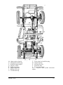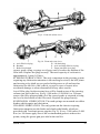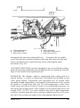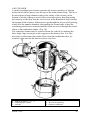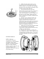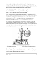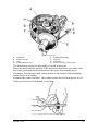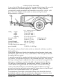
1
LAND
ROVER
OPERATION MANUAL
IMPORTANT
NOMENCLATURE
As this manual covers both Right and Left-hand Drive models, reference is
made throughout the text to the “left-hand” and “right-hand” sides of the
vehicle, rather than to the “near-side” and “off-side.” The “left-hand side”
is that to the left hand when viewed from the rear; similarly “left-hand
drive” models are those having the driving controls on the left-hand side,
again when the vehicle is viewed from the rear.
CAPACITIES
All capacities are quotes in Imperial and Metric measure; to ascertain the
U.S. equivalent, multiply the Imperial figure by 1.2.
GUARANTEE
In order to obtain the Certificate of Guarantee operative with your vehicle,
it is essential that you should, with the minimum of delay, either fill in and
post the guarantee form supplied or ask your supplier to do it for you.
Failure to do so may seriously jeopardise any claim you have on the
Company under the terms of the standard guarantee.
GEAR RATIOS
The Land-Rover is equipped with a transfer box giving a secondary series
of low gear ratios for heavy work. You are advised to consult “Gear
Changing Instructions” for full details of the operation of this transfer box.
LOCKING
To protect your Land-Rover against theft, always remove the ignition key
when parking. As an additional precaution the distributor rotor arm may
also be removed or the petrol tap on the sediment bowl turned “OFF.”
MAINTENANCE
In order to obtain maximum service and dependability from your LandRover, maintenance items listed in this manual should receive regular
attention. They are few in number and quite straightforward and will amply
repay the small amount of time which needs to be devoted to them.
OPERATION MANUAL
-- for the --
LAND ROVER
Regd. Trade Mark
1948-51 MODELS
Vehicles numbered:
R860001 to R863000
R8663001 onwards
R06100001 onwards
) Standard vehicle
) Right-hand drive.
)
L860001 to L863000
L8663001 onwards
L06100001 onwards
) Standard vehicle
) Left-hand drive.
)
R8670001 onwards
R06200001 onwards
) Station wagon
) Right-hand drive.
L8670001 onwards
L06200001 onwards
) Station wagon
) Left-hand drive.
R8680001 onwards
R06300001 onwards
) Welding outfit vehicle
) Right-hand drive.
L8680001 onwards
L06300001 onwards
) Welding outfit vehicle
) Left-hand drive.
(The prefix R is omitted from vehicles built to Home requirements, bearing serial numbers 06110348,
06200265 and 06300001 onwards).
THE ROVER CO. LTD.,
SOLIHULL, BIRMINGHAM, ENGLAND.
Telephone: SHEldon 2461.
Telegrams: Rover, Solihull.
A copy of this
operation manual is
sent out with each
SERVICE DEPT.
SOLIHULL, BIRMINGHAM, ENGLAND.
vehicle. Additional
Telephone: SHEldon 2461.
Telegrams: Rovrepair, Solihull.
copies are obtainable
London Service Station
SEAGRAVE ROAD,
FULHAM, LONDON S.W.6., ENGLAND.
from either of the
Telephone: FULham 1221.
Telegrams: Rovrepair, Wesphone, London.
PRICE – 5/-
addresses opposite.
ROVER PHONES:
Solihull (Head Office)
SHEldon
2461
Solihull Service Dept.
SHEldon
2461
London Service Station FULham
1221
APRIL, 1950.
Publication. No. TP/108/D
INDEX
A
Attachments, towing
Additives, oil
Additives, petrol
Adjustment, brake
Adjustment, clutch
Adjustment, distributor
Adjustment, fan belt
Adjustment, reverse stop
Adjustment, steering
Adjustment, tappet
Air cleaner
Anti-freezing mixture
Axles
B
Brake adjustment
Brakes
Brakes, bleeding
Battery
Box, control
Bulbs
C
Cable, high tension
Capacities (special note)
Capacities
Capacity, engine oil
Capacity, petrol
Capacity, water
Capstan winch
Carburettor
Carrier, spare wheel
Chaff guard
Chassis lubrication
Cleaner, air
Clutch
Clutch adjustment
Clutch lubrication
Coil
Controls
Control box
Control, ignition
Control, mixture
Coolant, draining
Cooler, oil
Cooling system
D
Dampers, hydraulic
Decarbonising
Description
Dimensions, vehicle
Dimensions, engine
Dipper switch, lamp
Distributor adjustment
Distributor lubrication
Distributors, Rover
91, 96
20
3
53
39
68
42
19
53
38
49
43
6, 29
53
6, 53
55
64
67
71
70
Inside front cover
7
5, 26
5, 45
5, 42
104
50
95
105
30
49
6, 39
39
27
68
10-14
67
36
11, 15
42
106
5, 40
55
35
7
7
5
10
68
27
(British Isles) 111-120
Distributors, Rover
(Overseas) 121-128
Doors
84
Draining Coolant
42
Dynamo
27, 66
E
Electrical equipment
64-76
Engine governor
105
Engine timing
36
Engine lubrication
21
Engine dimensions
5
F
Fan belt adjustment
42
Fault location
77-83
Filter, oil, external
26, 27
Foot pedals
10, 30
Foot pedal pads
95
Freewheel
6
Front axle lubrication
29
Front hub lubrication
29
Front wheel drive lock
13
Frost precautions
43
Fuel system
5, 44
Fuse
4, 67
G
Gauge, petrol level
13
Gearbox
6
Gearbox lubrication
28
Gear changing
16-19
Gear ratios
6
Governor, engine
105
Guarantee
2
H
Hand-rail, passenger
9
Heater, vehicle
93
Hoods
85-90
Horn
74
Horn button
10
Hub, front, lubrication
29
Hydraulic dampers
55
I
Ignition
5, 68-71
Ignition control
36
Ignition switch
12
Ignition warning light
12
In case of trouble
77-83
Instruments
10
Instrument panel light switch
12
Introduction
1
L
Lamps
71 –74
Lamp dipper switch
10
Lamp focussing
72
Lamp setting
72-73
Lamp switch
12
Level gauge, petrol
13
Location of faults
77-83
Location of Solihull factory
129
Lock, front wheel drive
13
Locking
Inside front cover
Lubricants, recommended
32-33
Lubrication
20-30
Lubrication, axles
29
Lubrication, chassis
30
Lubrication, clutch
27
Lubrication, distributor
27
Lubrication, engine
21
Lubrication, front hub
29
Lubrication, gearbox
28
Lubrication, propeller shaft
28
Lubrication, steering box
30
Lubrication, suspension
30
Lubrication, transfer box
28
Lubrication, upper cylinder
3
M
Maintenance points
31-35
Map of Solihull factory
129
Mixture, anti-freezing
43
Mixture control
11, 15
Nomenclature
Inside front cover
Numbers, vehicle
4
O
Oil additives
20
Oil capacity, engine
5, 26
Oil cooler
106
Oil filter, external
26, 27
Oil pressure
12, 26
Oil pressure warning light
12, 26, 76
P
Pad, foot pedal
95
Pedals, foot
10, 30
Petrol system
5, 44
Petrol additives
3
Petrol capacity
5, 45
Petrol level gauge
13
Petrol pump
46
Plugs, sparking
39
Power take-off
96-104
Precautions, frost
43
Pressure, oil
12, 26
Pressures, tyre
57
Propeller shaft lubrication
28
Pulley, rear power take-off
103
Pump, fuel
46
R
Ratios, gear
6
Rear axle lubrication
29
Recommended lubricants
32-33
Rover distributors
(British Isles) 111-120
Rover dealers
(Overseas) 121-128
Running-in period
2
S
Seats
84
Seats, rear
94
Sediment bowl
45
Setting lamps
72-73
Sidescreens
84
Spare wheel
9, 57
Sparking plugs
39
Special notes
2
Specification
5
Springs, road
55
Starter
12, 15, 68
Starter switch
12, 15
Starting
15
Station wagon
109-110
Steering
7, 52
Steering box lubrication
30
Suspension
6, 55
Suspension lubrication
30
Switch, dipper lamp
10
Switch, ignition
12
Switch, instrument panel light
12
Switch, lamp
12
Switch, starter
12, 15
Switch, windscreen wiper
13
T
Towing attachments
91, 96
Tappet adjustment
38
Technical Service
130
Timing
36
Tools
9-10
Trafficators
93
Trailer, Brockhouse
107
Transfer box
6, 13, 18
Transfer box lubrication
28
Transmission
6
Trouble finding
77-83
Tyre pressures
57
Tyres
56-63
U
Upper cylinder lubrication
3
V
Vehicle heater
93
Vehicle serial numbers
4
Ventilator, windscreen
95
W
Warning light, ignition
12, 75
Warning light, mixture
control 11, 15, 16, 75
Warning light, oil pressure
12, 26, 76
Water system
40
Water capacity
5, 42
Weights
7
Welding plant vehicle
108
Wheels
56-63
Wheel balancing
63
Wheel, spare
9, 57
Winch, capstan
104
Windscreen
9
Windscreen ventilator
95
Windscreen wiper
13, 74
Wiring diagram
Inside rear cover
INTRODUCTION
In the design of the Land-Rover every effort has been made to simplify as
far as possible the amount of attention which the owner must devote to
upkeep. For this manual we have endeavoured, by the use of illustrations, to
make the instructions for items of routine maintenance as simple and as
clear as possible. At the same time we realise that there may be occasions
when the owner finds himself in some difficulty; such cases are dealt with
by our Service Department and the
information given on Page 130 will
help you.
Operating instructions for the
standard vehicle are given on Pages
1-92, while details of extra
equipment are set out on Pages 93106; reference to the Land-Rover
Station Wagon is made on Page
109 and to the Welding Plant
version on Page 108.
“Occasions when the owner finds himself in
some difficulty”
In the event of spare parts being required, they may be obtained through the,
nearest Rover agent or in cases where difficulty ' experienced, directly from
us. A list of Rover Agents (both Home and Overseas) is given at the back of
this book.
It will be realised that from time to time, alterations in design and in the
make of various accessories occur and this operation manual, while being
kept up-to-date as far as possible, is not to be taken as a standard
specification of the Land-Rover.
We reserve the right, to alter the specification at any time and without
incurring any obligation to incorporate such alteration in vehicles already
delivered.
The purchaser is earnestly requested to fill in the Guarantee form supplied
with the vehicle, upon receipt of which we will place his name on our list of
owners and return the completed Guarantee form.
'I'HE ROVER Co. Ltd.,
SOLIHULL,
BIRMINGHAM,
ENGLAND.
APRIL 1950
1
SPECIAL NOTES
GUARANTEE.
In order to obtain the Certificate of Guarantee operative with your vehicle,
it is essential that you should, with the minimum of delay, either fill in and
post the guarantee form supplied or ask your supplier to do it for you.
Failure to do so may seriously jeopardise any claim you may have on the
Company under the terms of the standard guarantee.
COOLING SYSTEM.
The cooling system is pressurised and great care must be taken when
removing the radiator filler cap,
especially when the engine is hot, to
avoid steam which may be blown
out with considerable force.
I'HE RUNNING-IN PERIOD.
The years of good service expected
from your vehicle will depend to a
large extent upon the treatment it
receives in the early stages. It is
most important that your LandRover be properly “run-in”, that is,
it should, be given an initial period
“Avoid steam which may be blown out
of service during which it must be
with considerable force”
driven carefully at moderate speeds
so that no component is subjected to extreme loads.
We recommend a running-in period of 500 miles (750 Km.) during which
35-40 m.p.h. (55-65 k.p.h.) in high transfer ratio should not be exceeded,
but even after that the vehicle should not be driven at prolonged high speeds
until it has done 1, 000 miles (1,500 Km.); good use should be made of the
gearbox and a change-down to a lower gear made if the engine is subjected
to hard pulling in a high gear. Never race the engine when cold at any time
during the life of the vehicle.
The instructions pasted on the windscreen are only general and to get the
most lasting benefit the owner will not only obey these, but also see that he
does not, on prolonged stretches, do even 40 m.p.h. (65 k.p.h.) if it means
using full throttle during the first 500 miles (750 Km.).
APRIL 1950
2
It may well be that you desire to use the Land-Rover for other purposes
besides road-work, even when it is new; it may he required for driving,
stationary equipment or for cross-country work necessitating low transfer
ratio. In the latter case 15 m.p.h. (25 k.p.h.) should not be exceeded in top
gear whilst running-in, with correspondingly lower speeds in the
intermediate gears. For stationary work an engine speed of 2,000 r.p.m.
should be regarded as the maximum during the first five hours and this
figure can be raised to 3,000 r.p.m. for the next ten hours. As an engine
revolution indicator is not fitted to the Land-Rover, reference should be
made to the table below to ascertain the road-speed corresponding to these
figures and the hand-throttle marked to give these settings during a trial run
on the road.
ENGINE R.P.M.
2,000
3,000
ROAD SPEED
Top gear (high transfer).
Top gear (low transfer).
30 m.p.h. (50 k.p.h.).
12 m.p.h. (20 k.p.h.).
46 m.p.h. (70 k.p.h.).
17 m.p.h. (27 k.p.h.).
Your dealer will carry out a complete check-over on the vehicle after 750
miles (1.000 Km.) if used exclusively for road-work or after 30 hours when
mainly used in low transfer ratio for farming purposes. The inspection will
conform to the Free Service Card supplied with the vehicle and includes
changing the oil in the engine, gearbox, transfer box and axles. A second
check-over will be given after 1,500 miles (2.500 Km.) or 60 hours.
UPPER CYLINDER LUBRICATION.
During the early life of the vehicle we recommend the use of an upper
cylinder lubricant. It should be used in the proportion of one fluid ounce to
four gallons of petrol (three centilitres to twenty litres) and added to the
tank before filling with petrol to ensure thorough mixing.
We have tested and exclusively recommend the following lubricants:Wakefield's Castrollo.
Mobil Upperlube.
Shell Donax U.
or Energol U.C.L.
The addition of upper cylinder lubricant is not considered so essential after
the engine has been "run-in," but it can be continued without any
detrimental effect.
APRIL 1950
3
FUSE.
The single fuse fitted in the electrical
system protects the horn, windscreen
wiper, petrol tank gauge unit and rear stop
lights. It is situated under a bakelite cover
on the engine side of the scuttle panel on
the right-hand side a spare fuse is carried
under the same cover. In the event of a
failure occurring on any of the
components detailed, first examine the
fuse to make sure that it has not "blown."
“First examine the fuse”
VEHICLE SERIAL NUMBERS
The vehicle serial number will be
found on a plate fixed to the scuttle
panel. Owners are requested to quote
this number in all correspondence;
the registration number of the vehicle
is of no use whatever to us.
“The registration number . . . is of no
use whatever to us.”
Certain units also carry serial
numbers as detailed below, but they
should not be quoted unless specially
asked for, as we can identify them
from our records, providing the
vehicle number is given.
Chassis number is stamped on the top
of the left-hand front engine bearer bracket.
Engine number is stamped at the top front of the cylinder block on the lefthand side, adjacent to the water PUMP.
Gearbox number is stamped on the right-hand side of the casing at the rear.
Rear axle number is stamped on to of the axle casing on the left-hand side.
Front axle number is stamped on top of the axle casing on the left-hand
side.
APRIL 1950
4
GENERAL DATA AND DIMENSIONS
ENGINE. Four cylinders cast en bloc with detachable cylinder head.
Flexibly mounted on rubber at four points. Three crankshaft bearings; four
cam- shaft bearings. Vibration damper on crankshaft integral with fan
driving pulley. Overhead inlet valves operated by followers and push rods;
side exhaust valves by direct rockers from camshaft; camshaft is driven by
duplex chain automatically adjusted by hydraulic tensioner. Lubrication is
full pressure from gear-type oil pump to all bearings and valve gear.
External A.C. by-pass pressure filter and a gauze pump intake filter in the
sump.
Bore
Stroke
Cylinder capacity
Compression ratio
B.H.P.
R.A.C. Rating
Max. torque
Firing order
Sump capacity
69.5 mm. (2.736 in.).
105 mm. (4.133 in.).
1,595 c.c. (97.34 cu. in.)
6.8 - 1
50-55 at 4,000 R.P.M.
11.98 H.P.
80 lbs. / ft.(11 mKg.) at 2,000 R.P.M.
1, 3, 4, 2.
10 pints (5,5 litres).
COOLING. Impellor type water pump and fan driven from crankshaft.
Temperature controlled by thermostat. Pressurised system to decrease loss
of coolant under hard working conditions. Total capacity 17 pints (9,75
litres).
IGNITION SYSTEM. Battery and coil.
Distributor has both centrifugal and vacuum
advance and retard. Waterproof covers on
sparking plugs.
FUEL SYSTEM. Petrol from tank under
seat-box on right-hand side is delivered to
the Solex 32 P.B.I.2 down-draught
carburettor by electric S.U. pump. AC.
sediment filter between tank and pump. AC.
oil-bath air cleaner. Fuel capacity 10
Imperial gallons (45 litres).
“Waterproof covers on
Sparking Plugs”
APRIL 1950
5
CLUTCH. Single dry plate 9 in. (230 mm.) diameter.
MAIN GEARBOX. Single helical constant-mesh gears, with synchromesh
on top and third speeds.
TRANSFFR BOX. Two-speed reduction gears on main gearbox output.
Incorporates free-wheel unit in front axle drive.
TRANSMISSION. Hardy-Spicer open propellor shafts to front and rear
axles.
REAR AXLE. Spiral bevel pattern. Semi-floating axle shafts. Ratio 4.7-1.
(4.88-1 for axle numbers up to 861371).
FRONT AXLE. Spiral bevel differential. Drive transmitted through
enclosed constant velocity universal joints. Ratio 4.7-1. (4.88-1 for axle
numbers up to 861371).
OVERALL GEAR RATIOS. The table below gives the overall gear ratios,
i.e., total reduction obtained through main gearbox, transfer box and axles.
(Axles numbered 861372 onwards).
MAIN GEARBOX
Top gear
Third
Second
First
Reverse
TRANSFER BOX
High ratio.
Low ratio.
5.396
13.578
7.430
18.697
11.023
27.738
16.165
40.676
13.743
84.581
SUSPENSION. Semi-elliptic leaf springs with rubber bushes controlled by
telescopic hydraulic dampers.
BRAKES. Girling hydraulic brakes on all wheels. Handbrake applies
Girling mechanical brake on transfer box output shaft for parking purposes
only.
WHEELS. 16" divided or 16" well-base pattern.
TYRES. 6.00-16 or 7.00-16.
APRIL 1950
6
ELECTRICAL SYSTEM. Lucas 12-volt starting and lighting set. Battery
51 A.H. mounted at right of engine well clear ground.
STEERING. Burman worm and nut pattern.
VEHICLE DIMENSIONS.
Overall length
132 in. (3,35 m.).
Overall width
61 in. (1,55 m.).
Overall height
- hood up
70½ in. (1,79 m.).
- hood down, screen up
65½ in. (1,66 m.).
- hood down, screen down
53 in. (1,35 m).
Wheelbase
80 in. (2,03 m.).
Track
50 in. (1,27 m.).
Ground clearance
8½ in. (216 mm.).
Turning circle
(6.00-16 tyres)
35 ft. (10,5 M.).
(7.00-16 tyres)
40 ft. (12,2 m.).
Weight
- running (with water, oil and fuel)
2,604 lb. (1.136 Kg.).
- maximum approved gross loaded
4,032 lb. (1.829 Kg.).
Maximum approved pay load (in addition to passengers) 1,000 lb. (450 Kg.).
Maximum draw bar pull
(according to surface conditions).
1,200-2,000 lb. (550 to 900 Kg.).
Internal body dimensions
CAPACITIES.
Engine sump
Air cleaner
Main gearbox
Transfer box
Rear axle
Front axle
Tracta joints (each)
Fuel tank
Cooling system
- length
- width
- depth
37½ in. (952 mm.).
56½ in. (1,43 m.).
14½ in. (368 mm.)
10 pints (5,5 litres).
2 pints (1,0 litre).
4 pints (2,25 litres).
6 pints (3,5 litres).
3 pints (1,75 litre).
3 pints (1,75'Iitre).
1 pint (0,5 litre).
10 Imp. gallons (45 litres)
17 pints (9,15 litres).
DESCRIPTION
The main characteristics of the Land-Rover are brought out in Figs. 1 and 2;
there are, however, a few small points which may not be too clear from the
illustrations and which require explanation to ensure your obtaining the
maximum utility from the vehicle.
The front bumper (A) is retained by bolts and hence readily detachable to
facilitate straightening should it become damaged in service.
APRIL 1950
7
Fig. 1. (Three-quarter front view).
Fig. 2. (Three-quarter rear view).
A-Detachable front bumper.
B-3-pin socket.
C-Tailboard.
D-Tailboard key.
E-Tailboard chain.
F-Bonnet fastener.
G-Radiator grille panel.
APRIL 1950
H-Grille clamp.
J-Grille bracket.
K-Windscreen clamp.
L-Windscreen support.
M-Windscreen fastener.
N-Jack handle clips.
8
When towing a trailer, connection for the trailer tail and stop lamps are provided
by the three-pin-socket (B) fitted in the right-hand side of the rear chassis crossmember. (See "Towing Attachments").
The tailboard (C) can be lowered to its horizontal position by withdrawing the
keys (D). To remove the tailboard from the vehicle, unhook the two chains (E),
lower it as far as possible and slide off the hinges to the left.
Two spring fasteners (F) secure the bonnet top panel in the closed position; it
can be held in the open position by means of the stay rod clipped under the
panel on the left-hand side. The panel can be removed from the vehicle by
raising it to a vertical position and sliding off its hinges to the left.
The headlamps and horn are protected by the radiator grille (G) which is readily
removed by detaching the two bolts and clamps (H), and lifting out from the
brackets (J).
The hand-rail mounted on the dash is fitted for the convenience of front seat
passengers when traversing rough ground.
Provision is made for folding the windscreen down on to the bonnet (Fig. 2). To
do this, release the two clamps (K) from the dash panel and lower the
windscreen on to the supports (L); secure in this position by means of the spring
fasteners (M). To prevent rattles when not in use, these fasteners are normally
clipped to the bonnet panel (Fig. 1).
The spare wheel is stowed in the depression in the body floor (Fig. 2) and
retained by means of a clamp and wing-nut. When it is desired to utilise the
entire body space for load-carrying the spare wheel can be carried in the
alternative position on the bonnet top (Fig. 1). The mounting plate for this
purpose is supplied as an extra component. With the spare wheel carried in this
way, it is not possible to fold the windscreen into the horizontal position.
The hinged flap in the gearbox cover just to the rear of the main gear change
lever affords access to the gearbox oil filler and dip-stick, whilst that in the
centre of the seat-box covers the power take-off engagement lever. The locker
lid on the right-hand side of the seat-box, encloses the petrol tank and filler (see
Fuel System) and the brake fluid reservoir (see Brake System).
TOOLS. The small tools are carried in the locker under the seat-box on the lefthand side. Clips for the starting handle are fitted on the rear of the seat back-rest
panel and those (N) for the jack handle on the inside of the left-hand side panel
(Fig. 2). When certain items of special equipment are installed, the jack handle
is stowed in clips along the dash above the instrument panel.
APRIL 1950
9
The standard tool-kit supplied with each vehicle comprises:
Wheel brace
Lifting jack
Tyre pump
Oil gun
*Pliers
*Screwdriver
*Open-ended spanner (3/16 in.
x 1/4 in.)
*Open-ended spanner (5/16 in.
x 7/16 in.)
*Adjustable spanner
*Distributor screwdriver and feeler
gauge
*Spanner (3/8 in.)
*Sparking plug spanner
*Box spanner
*Tommy bar
*Tyre pressure gauge
Items marked * are contained in a leather tool roll.
CONTROLS AND INSTRUMENTS
The principal controls and instruments are illustrated on the opposite page,
where it will be seen that the layout is very similar to that on a normal car,
with the addition of gearbox transfer and front wheel drive lock controls.
Except for the positions of the steering column, foot-pedals and handbrake
lever, the layout is the same for both left-hand and right-hand drive
vehicles.
FOOT PEDALS. The three foot-pedals are normal in position and
operation, i.e., the left-hand pedal controls the clutch, the centre pedal the
foot brake and the right-hand pedal the accelerator.
HAND-BRAKE. The hand-brake lever protrudes through the front of the
seat-box, to the driver's left hand on a R.H.D. vehicle, and to his right hand
on a L.H.D. vehicle. In the "off" position it is parallel with the floor; to
apply the brake pull the lever upwards; to release, pull up slightly, depress
the small knob in the end of the lever and push downwards as far as
possible.
STEERING COLUMN. This is positioned either to the right or left-hand
side; in both cases, the horn push-button is fitted in the centre of the steering
wheel, with the headlamp dipper switch on the wheel boss.
Operation of this switch replaces the primary filaments in both lamps by
secondary "out-of-focus" filaments.
APRIL 1950
10
MIXTURE CONTROL. The mixture control is situated on the dash to the
right, below the instrument panel. It is marked “COLD START”
and its operation and also the action of the mixture control warning light are
fully described on Page 15. This light is amber in colour and is located in
the centre of the instrument panel at the top.
Fig. 3. Controls and instruments.
A-Clutch pedal.
B-Brake pedal.
C-Accelerator pedal.
D-Hand-brake.
E-Horn button.
F-Headlamp dipper switch.
G-Mixture control.
H-Mixture control warning light.
J-Ignition switch.
K-Starter switch.
L-Slow-running control.
M-Lamp switch.
N-Instrument panel light switch.
P-Lead lamp socket.
Q-Charging warning light.
APRIL 1950
R-Ammeter.
S-Oil pressure warning light.
T-Petrol level gauge.
U-Speedometer.
V-Access to petrol filler and brake fluid reservoir.
W-Windscreen wiper.
X-Main gear-change lever.
Y-Transfer box change lever.
Z-Front wheel drive lock.
AA-Access cover for gear-box filler.
BB-Location hole for seat.
CC-Access cover for power take-off control.
DD-Tool-box.
EE-Windscreen clamp.
11
IGNITION SWITCH. This takes the form of a barrel lock controlled by a
small yale-type key, situated in the centre of the main lamp switch on the
instrument panel. When the ignition is switched off, the key can be
withdrawn.
STARTER SWITCH. The switch operating the starter motor is located on
the dash to the left below the instrument panel. To operate, press the knob
and release as soon as the engine fires.
SLOW-RUNNING CONTROL. Situated to the right of the starter switch is
a slow-running control; by pulling out this control, the engine idling speed
may be increased when desired for stationary work. Prior to road Usage, the
idling speed should always be returned to normal to facilitate gear changing.
LAMP SWITCH. A rotary type lamp switch is located on the instrument
panel; turn the handle until the pointer registers with the required position:"OFF," "S" (side and tail) or "H" (side, tail and, headlamps).
INSTRUMENT PANEL LIGHT SWITCH. The " push-pull " switch
controlling the panel lights is situated at the top left-hand corner of the
instrument panel. It is only operative when the ignition is “ON.”
LEAD LAMP SOCKET. Below the panel light switch are a pair of sockets
which can be used either for a lead lamp or a trickle battery charger. The
electrical system being of the "positive earth" variety, the red socket is
earthed.
CHARGING WARNING LIGHT. The red warning light at the bottom
centre of the instrument panel glows when the dynamo fails to charge, or
when the charging rate is lower than the voltage of the battery; in the latter
case it will go out when the engine speed is increased above normal idling.
AMMETER. The ammeter is located to the right of the charging warning
light.
OIL PRESSURE WARNING LIGHT. The oil pressure warning light to the
right of the ammeter glows when, for any reason, the engine oil pressure
falls below a safe figure. Should this light, appear during normal operation,
stop the vehicle at once and ascertain the cause - usually low oil level in the
sump. Never operate the vehicle with low oil pressure as serious damage to
the engine will result.
APRIL 1950
12
PETROL LEVEL GAUGE. The petrol level gauge will always show ZERO
when the ignition is switched off. It must be stressed that, while the gauge
will always give a reliable indication of the petrol level, it is not a precision
instrument and therefore cannot be employed to derive accurate petrol
consumption figures. Such tests should always be made with an auxiliary
tank of known size.
PETROL FILLER. The petrol filler cap is located beneath the locker lid on
the right-hand side of the seat-box; when the cap is removed, a telescopic
tube may be drawn out of the tank neck to facilitate filling. The tank
capacity is 10 Imperial gallons (45 litres).
WINDSCREEN WIPER. A windscreen wiper is fitted on the driver's side
only. To set the wiper in operation, pull out the horizontal lever a short way
and turn it to clear the vertical lever; turn the latter to the right. To park the
blade, reverse the operations.
MAIN GEARBOX CONTROL. The main gear-change lever is situated in
the centre of the gearbox cover; it has five positions - four forward speeds
and reverse. For gear-changing instructions see Pages 16-19.
TRANSFER BOX CONTROL. The transfer box which gives two ratios in
the output from the main gearbox (i.e., making eight forward and two
reverse speeds in all) is controlled by the lever to the right of the gearbox
cover. Push the lever right forward for high ratio and pull right back for low
ratio. The lever should be left in the neutral (central) position when using
the power take-off pulley for stationary work. On no account must low ratio
be selected unless the vehicle is stationary with the clutch depressed. Full
instructions for the use of the transfer box are given on Pages 18-19.
FRONT WHEEL DRIVE LOCK. Four-wheel drive is fitted as standard on
the Land-Rover. The drive to the front wheels incorporates an over-run
freewheel unit which eliminates any undue tyre wear on the front wheels or
excessive strain on the transmission when travelling on hard surfaces.
The inclusion of this freewheel means that all four wheels are driving only
when the engine is pulling and the vehicle is travelling in a forward
direction. When reversing or the engine is coasting with the vehicle
travelling forward, the drive is to the rear wheels only. There may be
occasions when four-wheel traction is necessary in reverse while operating
on soft surfaces or in a forward gear when descending a steep, muddy
gradient and provision has therefore been made to "lock" the freewheel unit
and so obtain four-wheel drive under such conditions.
APRIL 1950
13
The control for this operation (known as the "FRONT WHEFL DRIVE
LOCK") takes the form of a knob on the gearbox cover. It is so arranged
that the freewheel can only be locked by pressing this knob downwards,
when the transfer lever is in 'LOW ratio; the unit is automatically returned
to its normal free condition when the transfer lever is returned to the HIGH
position on resuming hard surface travelling.
The control must only he operated when the vehicle is stationary.
Note:- On approximately the first 14,000 vehicles, the control takes the
form of a key ring in the right-hand floor board, instead of the knob. Its
operation is identical with the later version, except that the ring must be
pulled upward about ¼ in. (7 mm.) to lock the freewheel unit.
APRIL 1950
14
STARTING PROCEDURE
Before attempting to start the engine, read the special notes which follow.
SPECIAL NOTE MIXTURE CONTROL. The mixture control has three
positions and there is no graduation between them. The mixture is
NORMAL when the control is right in as far as it will go. The WARMINGUP position can be found by pulling out the control until a light click is felt;
it is a little more than half-way out. The RICH or STARTING position is
with the control right out. On no account leave the control in any position
between those indicated above and do not forget to push the control right in
as soon as the engine temperature will permit. The appearance of the
AMBER WARNING LIGHT on the instrument panel will indicate that the
control has been left out inadvertently and must be pushed right in.
SPECIAL NOTE ACCELERATOR. The carburettor is fitted with an
accelerator pump, the action of which is such that if the throttle is fully
depressed, an extra rich mixture is provided to assist acceleration. As this is
not wanted when starting the engine, except under abnormal starting
conditions, DO NOT TOUCH THE ACCELERATOR PEDAL at all if the
engine is COLD. It may assist starting a hot engine if the throttle is opened
half-way and released as soon as the engine fires. Never pump the
accelerator pedal under any circumstances.
Having read the special notes above, ensure that:1.
2.
The MAIN GEAR-CHANGE LEVER is in the NEUTRAL position,
that is to say, in the midway position between the gears. When in this
position it can be moved sideways the full width of the "gate."
The TRANSFER LEVER is in the HIGH gear position i.e., right
forward.
Then set the MIXTURE CONTROL to suit:(a) right out if the engine is cold.
(b) in the mid-way position if the engine is warm.
(c) right in if the engine is hot.
Finally, switch on the IGNITION; press the STARTER BUTTON and the
engine should start up after a turn or two.
APRIL 1950
15
FALSE START. If the engine makes
a false start when operating the
starter button, i.e., fires and does not
continue to run, but throws the starter
pinion out of mesh, it is imperative
to wait until the pinion and flywheel
comes to rest before again pressing
the starter button; failure to observe
this precaution may jam and bend the
“Should the engine fail to start . . .
shaft of the starter motor. Should the
ascertain why.”
engine fail to start after two or three
attempts, ascertain why it will not start, or the battery will run down
needlessly.
WHEN THE ENGINE STARTS. Except under conditions of extreme Cold,
the mixture control should be pushed in from the RICH (right out) position
to the WARM-UP (mid-way) position within a few seconds of the engine
starting. This period may have to be extended if conditions are severe, but
should never exceed a minute or so.
Do not race the engine, but it is permissible to drive away at moderate
speed, immediately after starting. This, or opening to about quarter-throttle
by means of the slow running control if the vehicle is to be used stationary,
is definitely advised, as lubrication of the cylinder walls by oil-fling is
thereby stimulated as the engine warms up. Continue with the mixture
control in the mid- way position until the engine temperature has risen
sufficiently to allow the knob to be pushed right in to the NORMAL
position. The appearance of the AMBER WARNING LIGHT on the
instrument panel will indicate that the control has been left out inadvertently
and must be pushed right in at once.
SPECIAL NOTE WARNING LIGHT. Like all mechanical devices the
mixture control warning system is not completely fool-proof and the
responsibility for pushing the mixture control to the normal position rests
with the driver, especially as the warning light may never appear owing to
bulb failure. As a guide the engine should always run satisfactorily in the
normal position within 1 mile (1 Km.) from starting away.
GEAR CHANGING INSTRUCTIONS
The positions of the main gear change lever are marked on the lever knob. It
should be noted that the only reverse stop is a spring in the selector
mechanism which tends to hold the lever away from the reverse selector
slot.
APRIL 1950
16
Throughout the instructions which follow, approximate speeds are quoted at
which the various gear-changes should be made. These are given only to
serve as a guide to owners who are unaccustomed to the Land-Rover;
naturally they can be modified considerably as experience is gained under
various operating conditions. At all times care should be taken against
"racing" the engine and a "change-up" should be made well before the
engine revolutions reach their peak.
Do not drive with the foot resting on the clutch pedal. To 'ride" the clutch in
this way causes excessive wear of the withdrawal mechanism.
GEAR CHANGING. (Transfer box in high gear).
CHANGING UP. Assuming, that the engine is running, to start the vehicle
from rest proceed as follows:Depress the clutch pedal fully, pause for a moment to allow the clutch shaft
to stop spinning and then move the gear lever into the first gear position.
Release the handbrake by pulling the lever slightly upwards, release the
catch by pressing down the knob on top of the brake lever and let the lever
go downwards. Accelerate slightly and at the same time allow the clutch
pedal to come back until you feel the clutch just gripping. Further gentle
pressure of the accelerator will be necessary as the clutch takes up the drive
and by this time the clutch should be right in.
After having set the vehicle in motion continue in first gear, speeding up the
engine until 5-8 m.p.h. (8-15 k.p.h.) is attained, when second gear should be
selected as follows:(i)
(ii)
Depress the clutch pedal fully, at the same time taking the foot off
the accelerator pedal.
Move the gear lever into neutral.
(iii)
(iv)
Pause (count " one, two ").
Move the gear lever gently into the second 'gear position.
(v)
Release the clutch pedal, at the same time pressing the accelerator
pedal gently down.
To change up from second to third speed, continue in second gear until
about 15 m.p.h. (25 k.p.h.) is reached. Then depress the clutch pedal fully,
at the same time releasing the accelerator, and move the gear lever towards
third gear position. It will be found to dwell for a moment, due to the
engagement of the synchromesh cones; do not force the lever, but maintain
a light pressure on it, and at the correct moment it will slip into third gear,
ensuring a silent and easy change. Release the clutch pedal and continue
with the acceleration.
APRIL 1950
17
Repeat these operations for changing from third to top gear speed of
approximately 20-25 m.p.h. (35-40 k.p.h.).
CHANGING DOWN. To change down from top to third gear, depress the
clutch pedal and ease the foot off the accelerator; move the gear lever gently
but firmly towards third gear position, when the same "dwell" will be felt
before third gear engages. Accelerate and let in the clutch.
When changing from third to second and from second to first gear, the
double de-clutch method should be used, as the synchromesh mechanism
does not operate on these two gears. Proceed as follows:(i)
Depress the clutch pedal and move the gear lever into neutral.
(ii)
Let in the clutch and accelerate until the engine speed is judged to
correspond with the vehicle speed in the gear to be selected.
(iii)
Again de-clutch and move the gear lever into the required position.
(iv)
Let in the clutch.
Do not snatch or force the gear lever; if the engine speed has been judged
correctly, the gear will engage quietly and smoothly.
REVERSE. To reverse the vehicle from a standstill, depress the clutch
pedal fully, engage reverse gear position and slowly release the clutch
pedal, at the same time gently speeding up the engine by means of the
accelerator pedal.
STARTING THE VEHICLE ON AN UPGRADE. When starting on an
upgrade is necessary, hold the vehicle with the handbrake and select first
gear; depress the accelerator in the normal way whilst simultaneously
releasing the handbrake and letting in the clutch.
USE OF THE TRANSFER BOX. The transfer box gives two ratios in the
output from the main gearbox, termed "high" and "low," thus giving a total
of eight forward and two reverse speeds in all. It is controlled by the lever to
the right of the gearbox cover; this has three positions - right forward for
high ratio, mid-way for neutral and right back for low ratio.
For normal usage and road work the lever should be in the high position and
the foregoing instructions for gear changing apply to this condition.
APRIL 1950
18
Low ratio is used when the
vehicle is to be operated on
heavy ground and for heavy
pulling. When low ratio is
employed
the
same
instructions for gear changing
should be followed except
that all the changes must be
“Low ratio is used . . . on heavy ground and
made at much lower vehicle
for heavy pulling.”
speeds, i.e., First to second within two or three vehicle lengths of starting.
Second to third - 6 m.p.h. (10 k.p.h.).
Third to top - 10 m.p.h. (15 k.p.h.).
The neutral position mid-way between "high" and "low" is quite definite
and is used with the power take-off pulley for stationary work; the vehicle
cannot be driven with this lever in neutral.
TRANSFER GEAR CHANGING. Changing from HIGH to LOW transfer
ratio should only be attempted when the vehicle is stationary. The engine
may be left running, but the main gear lever must be in the neutral position.
Depress the clutch pedal and pull the transfer change lever right back;
release the clutch. Should there be any hesitation in the gear engaging, do
not force the lever; either rock the vehicle backwards and forwards or, with
the engine running, engage a gear in the main gearbox and let in the clutch
momentarily; then return the main gear lever to neutral and try the transfer
control again.
Changing from LOW to HIGH transfer ratio may be accomplished at any
time, regardless of vehicle speed. Release the accelerator pedal, depress the
clutch pedal and push the transfer box lever right forward, pausing slightly
in the neutral position; let in the clutch.
REVERSE STOP ADJUSTMENT. The reverse stop is accessible after
removing the inspection cover from the right-hand side of the gearbox
cover. In the case of vehicles fitted with a control knob for the front wheel
drive lock, it is also necessary to remove the knob and control rod.
When the stop requires adjustment it should be set by means of the screw
and locknut on the stop hinge so that:(i)
the hinge rides easily up the gear lever when reverse gear is
selected and
(ii)
appreciable resistance is felt on moving the gear lever to the
reverse position.
APRIL 1950
19
LUBRICATION
GENERAL INSTRIFCTIONS. One of the, most important factors in the
performance and durability of any vehicle is its lubrication. This is
especially true of the Land-Rover because of the diverse conditions under
which it may be called upon to perform. We are in your hands; not being
able to stand over you and see that you put the right lubricant in the right
place at the right time, we can only lay down instructions and hope that they
will be carried out. You are earnestly advised, however, that the maximum
amount of trouble-free
service which you have a
right to expect from your
Land- Rover will only be
obtained if due and regular
attention is given to the
vital subject of lubrication.
The
lubricants
recommended for use on
the Land-Rover will be
found on Page 32, as well as on a plate attached to the radiator baffle. They
have been selected only after experimental work on our part in conjunction
with the oil refiners; as a result of the tests to which they have been
subjected, we find that the oils listed are pre-eminently suitable for the
Land-Rover and you are advised to use no other.
In cold weather, starting the engine may prove to be a serious problem if
oils heavier than those indicated are used and they would also affect fuel
economy and engine life, so when ordering your oil be careful to state the
GRADE as well as the MAKE.
We would advise you that we cannot hold ourselves responsible for damage
arising from the use of any additive to our recommended lubricants. The
oils we have selected are complete in themselves and afford every
protection in use. A warning is necessary against the addition of any oils or
other products, as these may materially impair the character of the lubricant
in use by dilution and so reduce its viscosity to danger point.
The pages which follow give complete instructions regarding the grade and
quantity of lubricant required for all parts of the vehicle; it should be
realised, however, that the intervals at which lubrication is carried out must
depend largely on the conditions of service under which any individual
vehicle is operated. The mileage intervals indicated should be adhered to
when your Land-Rover is mainly used for road work, but it is difficult to
APRIL 1950
20
quote accurate equivalent time intervals when the vehicle is employed on
field work or as a mobile power plant, owing to. the diversity of such
applications. An attempt has been made to give average intervals in terms of
operation hours and these should be followed as a general guide, but in
many cases this will largely be a matter that must be left to the good
judgement of the operator; obviously in dry dusty weather, certain
operations must be carried out much more frequently than during rainy
spells.
It should be constantly borne in mind that “over-lubrication," i.e.,
lubrication attention at comparatively short intervals, cannot do the slightest
harm to the vehicle, whereas the converse certainly can (and very often
will), seriously shorten its effective service life.
For convenience, the main lubrication points are shown on the plan views at
Figs. 4 and 5 and the more important attentions repeated in the "summary of
points requiring regular attention." on Pages 31, 34, 35.
ENGINE LUBRICATION
OIL LEVEL
It is necessary that the quantity of oil in the system be kept within specified
limits. Since a certain amount of oil is used up in the proper operation of the
engine, the supply must be replenished from time to time, this requirement
being additional to periodic changing of the oil. The amount of oil used will
depend largely, amongst other things, on the speed at which the vehicle is
driven.
A dip-stick is provided on the right-hand side of the engine and access to it
is gained by lifting the bonnet top panel
(Fig. 6). This stick carries two marks, H
(High) and L (Low) and the oil level
should always be maintained as near the H
mark as possible; on no account should it
fall below the L mark, in fact it is
desirable that this point is not even
approached.
Before taking a reading of the oil-level by
means of the dip-stick, the vehicle must
“On no account should it fall below
be placed on level ground and the engine
the ‘L’ mark.”
should be stationary long enough to allow
the oil to drain back into the sump from
the cylinder walls and overhead rocker gear, etc., a process which normally
takes about 30 minutes. Remove the dip-stick by pulling it straight upwards
out of its socket, making sure that no dirt drops into the sump; wipe the rod
clean, re-insert to its full depth and remove a second time to take the
reading.
APRIL 1950
21
Fig. 4. Upper plan view.
A – Rear axle filler.
B – Rear axle drain plug.
C – Rear axle breather.
D – Propellor shaft sleeve lubrication nipple.
E – Brake fluid reservoir.
APRIL 1950
F – Petrol filler cap.
G – Petrol tank drain plug.
H – Transmission brake adjuster.
J – Transfer box filler.
K – Transfer box drain plug.
L – Main gearbox filler.
22
M – Main gearbox dipstick.
N – Main gearbox drain plug.
P – Pedal lubricating nipples.
Q – Engine oil filter.
R – Engine drain plug.
S – Engine sump filter.
T – Radiator filler cap.
U – Coolant drain tap.
APRIL 1950
Fig. 5. Lower plan view.
V – Tracta joint level and filler plug.
W – Engine dipstick.
X – Steering box filler.
Y – Front axle filler.
Z – Front axle drain plug.
AA – Propellor shaft journal lubrication
nipples.
23
Fig. 6. Engine unit (right hand side).
A – Engine oil filler.
B – Oil level dipstick.
C – Oil drain plug.
D – Gauze Suction oil filter.
E – By-pass pressure oil filter.
F – Dynamo lubricator.
APRIL 1950
G – Fan belt adjustment.
H – Cylinder block drain tap.
J – Timing inspection cover.
K – Main gearbox oil filler.
L – Gearbox oil level dipstick
M – Transfer box oil filler.
24
Fig. 7. Engine unit (left hand side).
N – Transfer box oil level plug.
P – Oil pressure warning switch.
Q – Ignition control.
R – Thermostat housing.
S – Power take-off control.
T – Power take-off output.
U – Transmission brake (hand brake)
APRIL 1950
V – Clutch operation lever.
W – Mixture control warning light switch.
X – Main gearbox inspection cover.
Y – Main gear change lever.
Z – Transfer box change lever.
AA – Front wheel drive lock.
BB – Reverse stop adjustment.
25
Do not fill beyond the H mark, otherwise you may experience trouble with
sooted plugs and the engine may require more frequent decarbonisation than
is really necessary.
The engine oil-level should be checked daily in this way and topped up as
found necessary.
The oil pressure warning light on the instrument panel will glow when, for
any reason, the oil pressure drops below 10 to 12 lb. per sq. in. (0,7 to 0,8
Kg.). It will, therefore, light up when the engine is stationary and will go out
when the engine has started and the oil pressure has built up to exceed this
figure. Should the warning light appear at any time during normal vehicle
operation, the engine must be stopped immediately and the cause
ascertained; usually it will be due to low oil level in the sump.
ENGINE OIL CHANGES
Except under tropical or severe winter conditions, it is recommended that
the oil placed in the crankcase by the manufacturer be used for the first 750
miles (1.000 Km.) or 25 hours. Under such conditions, the engine oil should
be changed immediately upon receipt of the vehicle to the appropriate grade
as shown in this manual. At 750 miles (1.000. Km.), or 25 hours the oil
should be changed.
Thereafter, under good ROAD conditions, the engine oil need only be
changed at intervals of 3,000 miles (5.000 Km.) provided that the
EXTERNAL OIL FILTER is changed at every 9,000 miles (15.000 Km.).
When the vehicle is used primarily for industrial or dusty FIELD work, the
oil should be changed at each 75 hours, provided that the EXTERNAL OIL
FILTER is changed at every 300 hours.
It cannot be too strongly emphasised that, should the oil filter not be
replaced at these intervals, the engine oil must he changed more frequently.
DRAINING THE SUMP.
The engine oil is drained by removing the plug in the bottom of the sump on
the right-hand side. First run the engine to get the oil well warmed up,
remove the plug and allow plenty of time for the dirty oil to drain
completely away. Replace the plug and refill the engine by adding oil of the
correct grade through the filler cap on the left-hand side. The sump capacity
is 10 pints (5,5 litres).
At the same time it is advisable to inspect the gauze intake filter in the sump
and if necessary, clean it by washing in petrol.
APRIL 1950
26
The filter can be detached without removing the sump by unscrewing the
large brass plug on the right-hand side of the sump (Fig.6).
EXTERNAL OIL FILTER.
In addition to the coarse gauze suction filter in the sump, the oil is cleaned
by means of an AC. type ZS1 pressure filter mounted externally on the
engine. This filter continually cleans a proportion of the oil drawn from the
front end of the bearing gallery pipe, the return being direct to the sump by
external pipeline (Fig. 7).
It should be renewed at intervals not exceeding 9,000 miles (15.000 Km.) if
the vehicle is used primarily on the road and at every 300 hours if it is used
mainly for field work.
WATER PUMP.
The water pump bearings are pre-packed with grease and require no further
lubrication.
DYNAMO.
At about every 18,000 miles (30.000 Km.) or 500 hours, unscrew the
lubricator at the end of the dynamo (Fig. 6), lift out the felt pad and spring
and about half fill the lubricator with high melting-point grease. Replace the
spring and felt pad.
DISTRIBUTOR.
Every 3,000 miles (5.000 Km.) or 100 hours, lubricate the distributor as
follows:
(i) Lightly smear the cam with clean engine oil.
(ii) Lift off the rotor and add a few drops of thin machine oil to lubricate the
cam bearing and distributor shaft. Replace the rotor and push it on to the
shaft as far as possible.
(iii) Add a few drops of thin machine oil through the hole marked "OIL
HERE" in the contact-breaker base plate, to lubricate the automatic timing
control.
(iv) Place a small amount of clean engine oil on the contact breaker lever
pivot. Do not allow oil to get on to the contacts.
CLUTCH LUBRICATION.
The clutch withdrawal mechanism is lubricated from the gearbox; hence no
individual attention is required.
APRIL 1950
27
MAIN GEARB0X LUBRICATION.
Under extreme winter conditions, the oil should be changed on receipt of
the vehicle to the appropriate grade.
Every 1,000 miles (1.500Km.) or 30 hours, the main gearbox oil level
should be checked and replenished as necessary. The dip-stick and filler cap
on top of the gearbox are accessible through the cover plate on the gearbox
cover in front of the seat-box; the level should be kept up to the “H” mark
on the stick (Fig. 7).
The oil should be drained off after the first 750 miles (1.000 Km) or 25
hours and thereafter at each 3,000 miles (5.000 Km.) or 100 hours, by
removing the plug in the bottom of the gearbox casing (Fig. 5). Refill with
the correct grade; the capacity is approximately 4 pints (2,25 litres).
It is advisable to drain off the oil after a run when the unit is warm, as
draining will then be faster and more complete.
TRANSFER BOX LUBRICATION.
The transfer box, transfer case and freewheel are lubricated as one unit,
through a filler plug situated on the top panel of the transfer box (Fig. 6).
Under extreme winter conditions, the oil should be changed on receipt of
the vehicle to the appropriate grade.
Check the oil level every l,000miles,(1.500Km.) or 30 hours by removing
the level plug on the right-hand side of the box; this should be done
immediately after a run when the unit is warm; if any oil runs out of the
plug hole, allow it to do so, but if the level is low, add oil of the correct
grade through the filler hole until it reaches the bottom of the level hole.
Replace both plugs securely.
The oil should be completely drained after the first 750 miles (1.000 Km.).
or 25 hours and thereafter at every 3,000 miles (5.000 Km.) or 100 hours by
removing the plug in the bottom of the transfer box housing (Fig. 5). Refill
with new oil to the bottom of the level hole; the total. capacity of the unit is
6 pints (3,5 litres).
FRONT AND REAR PROPELLER SHAFT LUBRICATION.
Lubrication nipples are provided on the sliding portions of the front and rear
propeller shafts (Fig. 5). Every 1,000 miles (1.500 Km.) or 30 hours apply
one of the recommended oils at these two points, using the oil gun provided
in the tool kit.
Lubrication nipples are also fitted to the propeller shaft universal joints.
Every 3,000 miles (5.000 Km.) or 100 hours, apply the correct grade of oil
at these four points, preferably using the oil gun provided in the tool kit. If
high pressure greasing equipment is used, great care must be taken not to
damage the seals in the joints.
APRIL 1950
28
A – Oil filler/level plug.
B – Breather.
Fig. 8 Rear axle.
C – Brake bleed nipple.
D – Oil drain plug.
FRONT AND REAR AXLE LUBRICATION.
Under extreme winter conditions, the oil should be changed on receipt of
the vehicle to the appropriate grade.
While it is necessary to make sure that the axles receive sufficient
lubrication, it is important to avoid an excess of oil. This is especially so in
the case of the rear axle, where the oil may reach the brake shoes and cause
a serious loss in braking efficiency.
The oil levels should be checked at each 1,000 miles (1.500 Km.) or 30
hours, immediately after a run when the axles are warm. Remove the
combined level and filler plug from the axle casing banjo (on the right-hand
side on the rear axle and at the front on the front axle - Figs. 8 and 9); if any
oil runs out, allow it to do so, but if the level is low, add oil of the correct
grade, using a syringe or suitable funnel, until it reaches the bottom of the
filler hole. Replace the plug securely.
The oil should be completely drained after the first 750 miles (1.000 Km.)
or 25 hours and thereafter at every 3,000 miles (5.000 Km.) or 100 hours by
removing the plug in the bottom of the axle casing. Refill with new oil to
the bottom of the filler hole; the total capacity of each unit is approximately
3 pints (1,75 litre).
NOTE:- A second oil filler/level plug is provided on the front axle at the
rear of the differential casing; this is rather inaccessible on the vehicle, so
that usually the front plug will always be used.
TRACTA JOINT, SWIVEL PIN AND FRONT HUB LUBRICATION.
The Tracta joints, swivel pins and front hubs receive their lubrication from
common housings, the combined level and filler plugs being located at the
rear of the joint housings on the centreline of the axle (Fig.10).
Check the oil level in each joint at every 1,000 miles (1.500 Km.) or 30
hours by removing the plug immediately after a run when the unit is warm;
if any oil runs out, allow it to do so, but if the level is low, add oil of the
APRIL 1950
29
Fig. 9. Front axle (front view).
A – Axle filler/level plug.
B – Breather.
C – Brake bleed nipple.
Fig. 10. Front axle (rear view).
D – Oil drain plug.
E – Axle secondary filler/level plug.
F – Tracta joint filler/level plug.
correct grade, using a syringe or oil-gun, until it reaches the bottom of the
filler hole. Replace the plug securely. The total capacity of each unit is
approximately 1 pint (0,5 litre).
STEERING LUBRICATION. The only component in the steering system
requiring any lubrication attention is the steering box itself; the ball-joints
and steering relay shaft are pre-packed with grease or oil and need no
lubrication for the life of the vehicle, except in cases of repair after
accidental damage or when dismantled for any other reason.
An oil filler plug for the steering box will be found on top of the steering
column just above the box. Every 1,000 miles (1.500 Km.) or 30 hours,
remove the filler plug and add oil of the correct grade as required to bring
the level to the bottom of the filler neck. Replace the plug securely.
SUSPENSION LUBRICATION. The road springs are mounted on rubber
bushes which require no lubrication.
CHASSIS LUBRICATION. The only points on the chassis requiring
lubrication attention are the brake and clutch pedal shafts, which are
provided with Tecalemit grease nipples (Fig. 4). Every 3,000 miles (5.000
Km.) or 100 hours apply one of the recommended greases at these two
points, using the grease gun provided in the tool kit.
APRIL 1950
30
SUMMARY OF POINTS REQUIRING REGULAR ATTENTION
Use only the recommended lubricants listed on the two following pages.
These maintenance items are listed for the main part on a mileage basis, but
it will be appreciated that in many cases the necessity for attention is also
related to running hours, especially where the vehicle is used largely for
driving stationary equipment or slow-speed agricultural work.
Throughout the summary, page references are given on which the item
concerned is dealt with at length and, where applicable, some indication of
time interval is given. It is therefore most important that attention be
transferred to these pages at appropriate points.
DAILY:
Before starting the engine, check:
1. Level of oil in the engine sump. (Page 21)
2. Level of water in radiator. (Page 43).
WEEKLY:
1. TYRES. Check pressure and inflate if necessary (Page 57).
Examine tyres, for cuts and damage and remove any embedded flints,
etc.
2. WHFELS. Check wheel nuts for tightness.
3. BRAKES. Check the level of fluid in the hydraulic reservoir and
replenish if necessary. (Page 54).
AT FIRST 750 MILES (1.000 Km.):
1. Your dealer will carry out the first service check-over as detailed on the
Free Service Card supplied with the vehicle.
EVERY 1,000 MILES (1.500 Km.):
1. BATTERY. Check the acid level and replenish as necessary. (Page 64).
2. GEARBOX AND TRANSFER BOX. Inspect the oil levels and
replenish as necessary. (Page 28).
3. FRONT AND REAR AXLES. Inspect the oil levels and replenish as
necessary. (Page 29).
4. TRACTA JOINTS. Inspect the oil levels and replenish as necessary.
(Page 29).
Continued on Pages 34-35.
APRIL 1950
31
RECOMMENDED LUBRICANTS – I
Components and Conditions
ENGINE
AIR CLEANER
AND
GOVERNOR
UPPER CYLINDER
LUBRICANT
GEARBOX AND
TRANSFER CASE
Extreme Winter (below 10° F.)
DIFFERENTIALS
AND
TRACTA JOINTS
STEERING BOX
AND
LUBRICATION
NIPPLES
Normal (above 10° F.)
STEERING RELAY
LEVER (SEALED)
REAR POWER TAKEOFF AND PULLY UNIT
CAPSTAN WINCH
VACUUM
Agricultural
Car
-
Mobiloil Arctic
Special
Mobiloil Arctic
Mobiloil A
Mobiloil AF
Mobil
Upperlube
WAKEFIELD
Agricultural
Car
Car
Classification
Agricastrol Z
Castrol Z
Essolube 10
Essolube 10
S.A.E. 10W
Agricastrol LT
Agricastrol Medium
Agricastrol Heavy
Castrollo
Castrolite
Castrol XL
Castrol XXL
Castrollo
Essolube 20
Essolube 30
Essolube 40
-
Essolube 20
Essolube 30
Essolube 40
-
S.A.E. 20W
S.A.E. 30
S.A.E. 40
-
Castrol XXL
Castrol XL
Essolube 50
Gear Oil 80
Essolube 50
Gear Oil 80
Castrol ST
Gear Oil 80
Gear Oil 80
Winter (10° F. to 32 ° F.)
Summer (32° F. to 90° F.)
Tropical (above 90° F.)
Tractor Oil 620
Tractor Oil 630
Tractor Oil 640
Mobil
Upperlube
Normal (above 10° F.)
Extreme Winter (below 10° F.)
Tractor Oil 650
-
Mobiloil D
Mobiloil CW
Special
Agricastrol Heavy
Agricastrol Medium
Tractor EP
Gear Oil
-
Mobilube GX90 or
Mobilube EPW
Mobilube GX80
Agricastrol Gear
Oil EP
Agricastrol Gear
Oil EP
Agricastrol Gear
Oil Medium
Agricastrol Gear
Oil Medium
Extreme Winter (below 10° F.)
Normal (above 10° F.)
Extreme Winter (below 10° F.)
Tractor Gear Oil
140
-
Mobilube C
Mobilube CW
Special
ESSO
Agricultural
S.A.E. 50
S.A.E. 80
Gear Oil or
S.A.E. 30
Engine Oil
Castrol Hi-press Expee Compound Expee Compound S.A.E. 90EP
90
90
Castrol Hypoy 80 Expee Compound Expee Compound S.A.E. 80EP
80
80
Castrol D
Gear Oil 140 Heavy Gear Oil 140 Heavy S.A.E. 140
S.A.E. 80
Gear Oil or
S.A.E. 30
Engine Oil
Gear Oil 140 Heavy Gear Oil 140 Heavy S.A.E. 140
Tractor Gear Oil
140
Mobilube C
Agricastrol Gear
Oil Medium
Castrol D
Tractor Oil 620
Mobilube Arctic
Agricastrol
Light
Castrolite
Essolube 20
Essolube 20
S.A.E. 20W
Tractor Oil 640
Mobilube AF
Agricastrol
Heavy
Castrol XXL
Essolube 40
Essolube 40
S.A.E.40
NOTE: 10° F. = -12° C.; 32° F. = 0° C.; 90° F. = 32° C.
Wherever possible, the “Agricultural” grades of lubricant should be used; the corresponding “Car” grades are shown as alternatives when they
are not obtainable. If neither of these grades is available, good quality oils corresponding to the S.A.E. numbers may be used.
APRIL 1950
32
RECOMMENDED LUBRICANTS – II
Components and Conditions
ENGINE
AIR CLEANER
AND
GOVERNOR
UPPER CYLINDER
LUBRICANT
GEARBOX AND
TRANSFER CASE
DIFFERENTIALS
AND
TRACTA JOINTS
STEERING BOX
AND
LUBRICATION
NIPPLES
STEERING RELAY
LEVER (SEALED)
REAR POWER TAKEOFF AND PULLY UNIT
CAPSTAN WINCH
PRICE’S
SHELL
Agricultural
Car
Agricultural
Car
Classification
Extreme Winter (below 10° F.)
Olympia 10
Energol S.A.E. 10
-
S.A.E. 10W
Winter (10° F. to 32 ° F.)
Olympia F
Energol S.A.E. 20
Tractor Oil 20
Summer (32° F. to 90° F.)
Olympia M
Energol S.A.E. 30
Tractor Oil 20
Tropical (above 90° F.)
Olympia Y
Energol S.A.E. 40
Tractor Oil 20
Energol U.C.L.
Energol U.C.L.
Donax U
X.100-S.A.E. 10 or
Silver Shell
X.100-S.A.E. 20 or
Single Shell
X.100-S.A.E.30 or
Double Shell
X.100-S.A.E. 40 or
Double Extra Shell
Donax U
Normal (above 10° F.)
Olympia O
Energol S.A.E. 60
Tractor Oil 50
Olympia Y
Energol S.A.E. 40
Tractor Oil 30
X.100-S.A.E. 50 or
Triple Shell
X.100-S.A.E. 30 or
Double Shell
S.A.E. 50
Extreme Winter (below 10° F.)
Normal (above 10° F.)
Olympia EP
Energol EP S.A.E. 90
EP Tractor Gear Oil
S.A.E. 90 EP
-
Spirax 90 EP
S.A.E. 80
Gear Oil or
S.A.E. 30
Engine Oil
S.A.E. 90EP
Spirax 80 EP
S.A.E. 80EP
Tractor Gear Oil
S.A.E. 140
Tractor Oil 30
Spirax C-S.A.E. 140 or
Dentax 140
X.100-S.A.E. 30 or
Double Shell
S.A.E. 140
Extreme Winter (below 10° F.)
Normal (above 10° F.)
Extreme Winter (below 10° F.)
S.A.E. 20W
S.A.E. 30
S.A.E. 40
-
-
Energol EP S.A.E. 80
Olympia Gear D.K.
Energol S.A.E. 140
Olympia Amber
Energol S.A.E. 90
Olympia Gear D.K.
Energol S.A.E. 140
Tractor Gear Oil
S.A.E. 140
Spirax C-S.A.E. 140 or
Dentax 140
Olympia F
Energol S.A.E. 20
Tractor Oil 20
X.100-S.A.E. 20 or
Single Shell
S.A.E. 20W
Olympia Y
Energol S.A.E. 40
Tractor Oil 40
X.100-S.A.E. 40 or
Double Extra Shell
S.A.E.40
S.A.E. 80
Gear Oil or
S.A.E. 30
Engine Oil
S.A.E. 140
NOTE: 10° F. = -12° C.; 32° F. = 0° C.; 90° F. = 32° C.
Wherever possible, the “Agricultural” grades of lubricant should be used; the corresponding “Car” grades are shown as alternatives when they
are not obtainable. If neither of these grades is available, good quality oils corresponding to the S.A.E. numbers may be used.
APRIL 1950
33
5.
6.
7.
STEERING BOX. Remove the filler plug and top up with oil as
required (Page 30).
PROPELLER SHAFTS. Lubricate the nipples on the sliding joints
(Page 28).
BRAKES. Adjust as necessary. (Pages 53-55).
AT FIRST 1,500 MILES (2.500 Km.):
1. Your dealer will carry out the second service cheek-over as detailed on
the Free Service Card supplied with the vehicle.
EVERY 3,000 MILES (5.000 Km.):
1. ENGINE. Drain the sump, clean the gauze intake and refill with fresh
oil. (Page 26).
Clean and refill the air cleaner. (Page 50).
2. SPARKING PLUGS. Inspect and re-set gaps to .023-.026 in. (0,600,65 mm.) if necessary.
3. TAPPETS. Cheek tappet adjustment. (Page 38).
4. DISTRIBUTOR. Lubricate as described on Page 27.
5. DYNAMO AND FAN BELT. Check tension and adjust as required.
(Page 42).
6. CLUTCH. It is important to see that correct free movement is
maintained at the pedal pad. Adjust as required. (Page 39).
7. GEARBOX AND TRANSFER BOX. Drain off the oil and refill with
fresh lubricant. (Page 28).
8. FRONT AND REAR AXLES. Drain off the oil and refill with fresh
lubricant. (Page 29).
9. FRONT AND REAR AXLES. Check tightness of U-bolts securing the
axles to the springs.
10. PEDALS. Lubricate the nipples or the pedal spindles. (Page 30).
11. WHEELS. Change round all wheels to give them equal spells of duty.
(Page.57).
12. PROPELLER SHAFTS. Lubricate the journal nipples (Page 28).
EVERY 6,000 MILES (10.000 Km.):
1. FUEL SYSTEM. Clean sediment bowl and fuel pump filter. (Pages 45
and 46).
2. DISTRIBUTOR. Clean and cheek as described on Page 68.
3. BRAKES. If the brakes have been harshly used, relining may be
desirable.
APRIL 1950
34
EVERY 9,000 MILES (15.000 Km.).
1. ENGINE. Replace the AC. external oil filter. (Page 27).
EVERY 18,000 MILES (30.000 Km.):
1. DYNAMO. Lubricate as described on Page 27.
GENERAL. A few spots of oil should be applied to all exposed joints, such
as throttle joints, brake joints, door locks and hinges, etc., as frequently as
possible - at least once every month. At the same time it is a sound practice
to look over such points as wiring (where this is exposed), brake pipes and
control rods for signs of chafing which might cause "shorts" or leaks.
DECARBONISING
It is not possible to lay down any hard and fast rule concerning the mileage
intervals at which the engine should be decarbonised and the valves ground
in, for it is not actually necessary to carry out the operation until there is a "
fall-off " in performance. As that condition is not always readily detected
under varying conditions of service, your nearest Rover dealer will always
be pleased to advise you on the matter. If you are in any doubt at all, it is far
better to depend upon mileage as your guide and decarbonise and grind in
the valves every 9,000 miles (15.000 Km.). In cases where the vehicle is
used almost exclusively for 'stationary work, decarbonising should be
carried out at intervals of 300-500 hours.
APRIL 1950
35
ENGINE TIMING
OCTANE SELECTOR.
The timing of the ignition is controlled automatically by mechanism in the
distributor. In addition, an octane selector is fitted. This is a vernier
adjustment attached to the distributor (Fig. 7) fitted with a sliding portion
controlled by an adjusting screw and a calibrated scale marked R (retard)
and A (advance) with a number of divisions between. The standard setting
for the ignition is with the long line of the scale on the sliding portion
against the mark on the selector body, thus leaving one division further
possible advance and four divisions retard.
This setting is correct for any normal fuel and with a clean engine, but
should pinking develop as a result of the need for decarbonising, the control
can be retarded a little by turning the screw in an anti-clockwise direction.
Do not forget to return it to the original position after decarbonising.
In certain countries very low grade fuel is supplied, in which case it may be
necessary to adjust the octane selector to avoid pinking, even with a clean
engine.
FLYWHEEL MARKINGS.
The flywheel markings and timing pointer are visible when the inspection
cover on the right-hand side of the flywheel housing is removed. (Fig. 6).
The markings and their meanings are as follows:(1) The line against which the letters T.D.C. are stamped, when brought
dead opposite the pointer, means that No. 1 piston is on Top Dead
Centre, i.e., at the top of its stroke.
(2) The line against which the letters F.A.15° are stamped, when set
opposite the pointer, indicates the firing-point of No. 1 cylinder when
the octane selector is set in the standard position on the sliding scale
(i.e., the point at which the distributor points should be just opening,
with the rotor in the firing position for No. 1 or No. 4 cylinder). It is
15° before T.D.C. (4 flywheel teeth). Disregard the other F.A. marks
at 7°, 8°, and 11° on certain flywheels.
(3) The line against which the letters E.P. are stamped, when set opposite
the pointer, indicates the point at which No. 1 exhaust valve should be
at the peak of its lift (fully open). It is 114° before T.D.C. (31 flywheel
teeth).
APRIL 1950
36
VALVE TIMING.
If the timing chain and hydraulic tensioner should have been removed, the
procedure to re-time the engine is as follows (See Fig. 11).
(1) Set the exhaust tappets as instructed on Page 38 and slacken the inlet
tappet adjusting screws as far as possible.
(2) Rotate the camshaft in the running direction until No. 1 exhaust valve
is fully open.
The use of a dial indicator is the only reliable method of determining this
point. It should be mounted on a stud adjacent to No. 1 exhaust rocker and
with its aid the possibility of an error in determining the exhaust peak is
eliminated. It is possible to
Fig. 11 Timing Gears
A – Camshaft chainwheel
B – Crankshaft chainwheel
C – Jockey pulley
D – Hydraulic tensioner
APRIL 1950
E – Pawl
F – Ratchet
G – Timing chain (driving side)
H – Jockey pulley arm
37
do the job correctly without a dial indicator, but much time is wasted and
the possibilities of an error very much magnified.
(3) Rotate the engine in the running direction until the E.P. mark oil the
flywheel is in line with the pointer.
(4) Fit the timing chain, ensuring that there is no slack on the driving side
(G).
(5) Hold the ratchet pawl (E) clear and replace the complete pulley (C, F
and H), meshing the pulley with the chain.
(6) Check the timing and correct if necessary. The camshaft chainwheel
(A) is made with three irregularly spaced keyways, so that if the timing
will not come correct in the first position tried, alternatives are
provided.
(7) Replace the hydraulic tensioner (D), comprising cylinder, piston and
spring; these items must be assembled dry to prevent the formation of
an air lock. Retain at its upper end with a split pin. Fit the circlip at (H),
retaining the jockey pulley assembly. Engage the ratchet (E, F).
(8) Set the inlet tappets as instructed below.
IGNITION TIMING.
(1) Check the contact breaker clearance and adjust if necessary using the
combined feeler gauge and screwdriver supplied in the tool kit. The
correct gap with the points fully open is .012 in. (0,30 mm).
(2) Rotate the engine in the running direction until the FA15° mark on the
flywheel is in line with the pointer, with both valves on No. 1 cylinder
closed.
(3) The rotor of the distributor will now correspond with No. 1 cylinder
high tension lead terminal.
(4) Set the octane selector to the standard position on the sliding scale.
(5) Set the distributor points just breaking by slackening the ¼ in. pinch
bolt at the base of the distributor head and rotate the distributor bodily
in the required direction. Do not forget to re-tighten the pinch bolt.
TAPPET ADJUSTMENT.
The firing order is 1, 3, 4, 2. The correct tappet clearance is .010 in.
(0,25mm.) on the inlet valves and .012 in. (0,30 mm.) on the exhaust valves,
with the engine either cold or at running temperature. Adjustment for this
clearance is provided by a set-screw and. lock-nut on the rocker. (See Figs.
12 and 13). When adjustment is required, slacken the lock-nut and rotate the
APRIL 1950
38
set-screw to give the correct clearance by means of a screw- driver. The
lock-nut should be securely tightened after adjustment, great care being
taken to ensure that this operation does not upset the clearance.
Fig. 12. Inlet tappet adjustment
Fig. 13. Exhaust tappet adjustment
A – Tappet adjusting screw B – Lock nut C – Feeler gauge
The tappet clearance should be set with the engine either cold or at running
temperature and it is essential to ensure that the valve to be adjusted is
really closed. To do this, set the valve receiving attention fully open and
then move the engine one complete turn to bring the tappet on to the back of
the cam. It cannot be urged too strongly that the clearance must be correct if
the best results are to be obtained.
SPARKING PLUGS.
Lodge HLNR sparking plugs are fitted as standard equipment. Every 3,000
miles (5.000 Km.) or 100 hours, the plugs should be removed and cleaned
and the electrode gaps re-set to .023-.026 in. (0,60-0,65 mm.) if necessary.
CLUTCH
The clutch should be used purely for starting the car from rest and when
changing gear. It is bad driving and detrimental to any clutch to "coast" hills
with the clutch pedal depressed, or to make a habit of slipping the clutch
when rounding corners, etc.
The clutch pedal adjustment is correct when there is ¾ in. (20 mm.) free
movement measured at the pedal pad and the linkage should be re-set when
the movement falls below this figure. Adjustment is provided by a nut on
the end of the rod connecting the pedal to the clutch operating lever on the
bell-housing; this nut is machined so that it locks itself at every half-
APRIL 1950
39
Fig. 14. Clutch adjustment
A – Clutch adjustment nut
B – Clutch pedal shaft
C – Brake master cylinder
D – Brake pedal shaft
E – Stop-light actuating spring
F – Brake pull-off spring
turn against the joint-pin in the pedal lever. To increase the free pedal
travel, turn the nut in an anti-clockwise direction half a turn at a time and
make sure that the nut is against the pin, before checking the pedal
movement. (Fig. 14).
COOLING SYSTEM The system is designed to give very efficient cooling
under all operating conditions, provided that the service attentions listed on
Page 43 are carried out at regular intervals.
RADIATOR. The radiator, which is constructed with cooling gills of a
special design, is cowled to shroud the four-bladed fan mounted on the
water pump spindle. Evaporation and consequent loss of coolant when
operating at high temperature is prevented by pressurisation of the system
by means of a sealed type filler cap. The cap incorporates a relief valve
which opens and allows steam to escape at a predetermined pressure; by
this means the boiling-point of the coolant is raised appreciably above the
normal 100'C. (212'F.). It is most unlikely that such a high temperature
would be reached under the most exacting conditions and even if it were,
the relief valve permits the engine to be kept running without risk of
APRIL 1950
40
Fig. 15. Radiator filler cap
A – Pressure relief valve (steam escape → → →)
B – Depression relief valve
damage. A vacuum valve is also fitted to the filler cap to relieve the
depression resulting when the engine has cooled down after running at
extremely high temperatures.
The standard radiator cap incorporates a relief valve which opens at
approximately 5 lb. per sq. in. (0,35 Kg/cm2.). A special cap is available as
an item of extra equipment for use when the vehicle is employed under very
hot conditions or for prolonged periods of stationary work; the relief valve
in this pattern opens at approximately 15 lb. per sq. in. (1,05 Kg/cm2.).
When removing the filler cap, first turn it anti-clockwise to the stop and
allow all pressure to escape before pressing it down and turning further in
the same direction to lift it off.
The radiator block drain tap is situated at the bottom on the right-hand side.
WATER PUMP.
The centrifugal pattern water pump is designed to give maximum service
between overhauls and no adjustment is provided or necessary. It is
mounted on the front of the cylinder block and, together with the fan, is
driven by a pulley and "V" type belt from the crankshaft. (The belt also
drives the dynamo). The sealed double-row ball bearing, integral with the
pump spindle, is pre-packed with high melting point grease and requires no
further lubrication throughout its life.
THERMOSTAT.
The thermostat is fitted in the housing at the front of the cylinder head
above the water pump casing, to which it is connected by a tube and rubber
APRIL 1950
41
joint ring. Its purpose is to provide rapid warming-up by causing the coolant
to circulate only round the engine until a predetermined temperature is
reached, when it opens to allow full circulation through the radiator. The
unit operates at 167 – 190 F. (75 – 88 C.) and this setting cannot be altered
in any way.
If overheating of the engine should occur, check that the thermostat is
functioning correctly; to do this, remove the thermostat from its housing
and run the engine; if the overheating is eliminated the unit is faulty and
must be replaced.
FAN BELT.
As the belt is of the "V" type, the drive is on the sides of the belt and it is
not therefore necessary to adjust it tightly and so put an excessive load on
the water pump and dynamo bearings. The tension is correct when it is
possible to depress the belt by thumb pressure approximately ½ in. to 1 in.
(12 mm. to 25 mm.), at a point midway between the fan and crankshaft
pulleys. Adjustment of the belt tension is provided by slackening off the
two nuts on the dynamo pivot bolts and the set-bolt retaining the adjusting
link to the dynamo, moving the dynamo outwards until the setting is correct
and re-tightening the nuts and set-bolt.
DRAINING THE COOLING SYSTEM.
The cooling system should be flushed out at least twice each year. It can be
completely drained by opening the taps on the radiator block and on the
right-hand side of the cylinder block at the rear; remove-the radiator filler
cap to prevent a vacuum which may impede thorough draining. When the
water has ceased to flow, a piece of wire should be inserted in each tap to
make sure that a blockage has not been caused by rust or scale from the
system. Place a hose in the radiator filler neck and adjust the flow of water
to equal that draining from the two taps; start the engine and allow it to run
until the whole cooling system has been thoroughly washed out. Switch off
the engine, close the taps, refill the radiator with clean water to the bottom
of the filler neck and replace the filler cap. When filling, use soft water for
preference (rain water will do), as this prevents to a great extent furring up
of the inside of the radiator, cylinder jackets and pipes. The capacity of the
system is 17 pints (9,5 litres)
CLEANING RADIATOR.
In the event of the cooling gills of the radiator becoming blocked with dirt,
straw, etc., they should be cleaned by means of compressed air or water
pressure applied from the rear, so forcing the foreign matter out through the
front of the radiator. Never use a metal implement for this purpose or
serious damage may result to the radiator core.
APRIL 1950
42
SERVICE ATTENTION.
It is a good plan to always inspect the cooling system at the same time as
the engine oil level is checked, i.e., daily under normal conditions. This care
would largely prevent the possibility of a sudden and costly delay due to
coolant loss and consequent engine failure. The inspection need only take a
few moments and should include the following points:(i)
Water level in radiator – should be to the bottom of the filler neck.
(ii)
Condition of all water hoses – freedom from cracks and hose clips
tight.
(iii)
Fan belt tension – a loose belt will lower the efficiency of the
pump and fan and cause overheating.
(iv)
Check for water leaks.
FROST PRECAUTIONS.
In cold weather, when the temperature may drop below freezing point,
precautions must be taken to prevent freezing of the water in the cooling
system.
As a thermostat is fitted to the Land-Rover, it must be appreciated that it is
possible for the radiator block to freeze when running in cold weather, even
though the engine temperature is quite high; for this reason the use of an
anti-freezing mixture is absolutely essential. As some anti-freezing
solutions have a corrosive effect upon the thermostat and other portions of
the cooling system, we have found it necessary to recommend only pure
ethylene glycol or good glycol-base solutions such as "Bluecol"; for your
own protection we advise you, wherever possible, to use nothing else.
Anti-freezing solutions are far more "searching" at joints than water; before
using them in your Land-Rover, it is therefore important to ensure that the
cooling system is leak-proof. If any doubt exists regarding the condition of
hoses, etc., they should be replaced. The table below gives the percentage
volume of Bluecol required to safeguard against temperatures down to
-40°F. (-40°C.).
Temperature Range
Above 32 °F (0 °C)
To 12 °F (-11 °C)
To –4 °F (-20 °C)
To –20 °F (-29 °C)
APRIL 1950
Coolant Strength
100% water
86% water
14% Bluecol
80% water
20% Bluecol
76% water
24% Bluecol
70% water
30% Bluecol
Quantity
17 pints (9,5 litres)
14.5 pints (8,0 litres)
2.5 pints (1,5 litres)
13.5 pints (7,5 litres)
3.5 pints (2,0 litres)
13.0 pints (7,0 litres)
4.0 pints (2,5 litres)
11.75 pints (6,5 litres)
5.25 pints (3,0 litres)
43
The anti-freezing mixture should be well mixed to the required strength in a
separate container and added after thoroughly flushing out the system (do
not simply add the correct amount of glycol through the radiator filler); run
the engine for a short while to assist good circulation.
It is important when the winter is over, that steps be taken not only to drain
off the mixture, but to flush the system through several times with very hot
soda water in order to remove all traces. Failure to take this precaution may
eventually, after a season or two of neglect, lead to the complaint of boiling.
If the vehicle is to be stored, in cold weather, unless it is kept in a wellheated garage or anti-freezing solution has been added to the coolant, the
system must be completely drained as instructed under "DRAINING THE
COOLING SYSTEM" above. After the water has drained out, it is well to
run the engine at a fast idling speed for not more than half a minute, so as to
dry out any water that may have been retained in the bottom of the
jacketing.
THE FUEL SYSTEM
The fuel system comprises the tank, pipe lines, sediment bowl, pump,
carburettor and air cleaner. It is most important that the system be kept
clean and free from water; periodically inspect for leaks.
Should the vehicle be stored for an extended period, it is well to completely
drain the system to prevent the formation of gum which may cause trouble
in the pump and carburettor. To effect complete draining, remove the drain
plug in the bottom of, the tank and replace when the tank is empty (Fig. 5);
then run the engine until the petrol in the pipes and carburettor is used up.
FUEL TANK.
Petrol is carried in a tank below the front seat-box on the right-hand side. It
rests in a stout steel cradle which forms a double bottom and protects the
tank proper from damage by stones thrown up from the wheels or contact
with any obstacle. The cradle is carried up both in front of and behind the
tank, lipped over and bolted to the brackets on the chassis frame, thus
relieving the tank of any strain due to possible slight distortion of the
chassis frame under extreme conditions of use.
APRIL 1950
44
The filler is readily accessible by lifting the lid in the top of the seat-box on
the right-hand side
(Fig 4). Except on a
few early vehicles, a
strap is provided on
the back-rest panel
to hold the lid in the
open position. Turn
the cap in an anticlockwise direction
to lift it off, which
action will reveal a
filler tube which can
be drawn out and
locked by a slight
movement to the
left, to facilitate
filling. Care should
be taken to prevent
“Care should be taken to prevent the entry of water.”
the entry of water or
foreign matter. The capacity of the tank is 10 Imperial gallons (45 litres).
The filler tube may be completely withdrawn to clean the gauze filter in its
lower end; a drain plug is provided in the bottom of the tank. The petrol
level unit is mounted in the top of the tank and requires no attention.
Immediately in front of the filler is the petrol feed pipe extending
downwards to the bottom of the tank, the lower end is shrouded with fine
mesh wire gauze to form a second filter, which being surrounded by petrol
is most unlikely to become choked.
SEDIMENT BOWL. Inserted in the feed pipe from the tank to the pump is
a sediment bowl mounted on the right-hand side of the scuttle. Any foreign
matter in the fuel settles in the glass bowl which can be removed for
cleaning in petrol by slackening the thumbscrew below the bowl and
swinging aside the wire holder. A fine gauze will be found in the body of
the unit; this should also be removed and washed in petrol. When reassembling, take care to replace the gauze correctly over the square inlet
nozzle, and also ensure that the cork sealing washer for the bowl is in good
condition.
The sediment bowl should be inspected and cleaned if necessary at the same
intervals as the petrol pump filter, i.e., at every 6,000 miles (10.000 Km.).
APRIL 1950
45
Fig. 16. Sediment bowl
A – Thumbscrew
B – Glass bowl
C – Joint washer
D – Filter gauze (fuel outlet)
E – Fuel inlet
F – Shut-off tap
A screw-down petrol supply shut-off tap is incorporated in the top of the
sediment bowl and this will normally be left in the "ON" position; it is not
necessary to close the tap when parking the vehicle, but this action would
serve as a precaution against theft.
FUEL PUMP. The S.U. electric fuel pump is mounted on the scuttle; it is
wired through the ignition and hence will only operate when the ignition
switch is "ON.” Easy starting of the engine is assured, as the pump fills the
carburettor float chamber immediately the ignition is switched on.
The pump is of the diaphragm type and will give prolonged service with the
minimum of attention.
A gauze filter (A) is incorporated which can be easily withdrawn by
unscrewing the hexagon brass plug (B) in the bottom of the pump body.
The only maintenance normally required is the cleaning of this filter at
every 6,000 miles (10.000 Km.) clean thoroughly in petrol using a stiff
brush, never use rag.
Should fuel pump trouble be suspected, first disconnect the union at the
pump end of the pipe from the pump to the carburettor and switch on the
ignition. Satisfactory performance of the pump will then indicate that the
fuel shortage is due either to blockage of the flexible pipe to the carburettor,
APRIL 1950
46
or more possibly to the carburettor float needle sticking up. If the pump will
not function proceed as follows:(i)
(ii)
(iii)
(iv)
(v)
(vi)
Check that the pump filter is clear.
Detach the sediment bowl and clean if necessary.
Check that the pipe from the pump to the sediment bowl is clear by
blowing down it with a tyre pump from the fuel pump end.
Check that the pipe from the sediment bowl to the tank .is clear by
blowing from the bowl end.
Reconnect the pipes and replace the sediment bowl.
Test the system for correct functioning.
Should the pump still not work satisfactorily, it may be due to a poor
electrical connection or dirty contact points, which should he checked as
follows:(i)
(ii)
Disconnect the feed wire from the terminal (D) on the bakelite
cover and strike it against the scuttle; the appearance of sparks will
indicate that the current supply is in order.
Remove the bakelite cover and touch the terminal with the lead. If
the pump does not operate when the points are in contact and a
spark cannot be struck off the terminal, it is probable that there is
some dirt on the points (F). These may be cleaned by inserting a
piece of card between them, pinching them together and sliding the
card backwards and forwards.
Failure to rectify the trouble with this treatment will indicate that the pump
itself is at fault, due to there being too much tension on the diaphragm. To
release this tension, remove the body from the base of the pump by undoing
the small screws which hold these two parts together. (The pump earth wire
will be released from one of these screws). The diaphragm (G) will he
adhered to the body of the pump and must be separated with the aid of a
knife; care should be taken to prevent the diaphragm support rollers (H)
from falling out during this operation. Replace the body on the pump base
and assemble the screws loosely; before finally tightening it is advisable to
stretch the diaphragm to its highest possible position by switching on the
pump and holding the contact points together whilst tightening the screws.
APRIL 1950
47
Fig. 17. Fuel pump.
A – Gauze filter
B – Filter plug
C – Earthing terminal
D – Feed terminal
E – Bakelite cover
F – Contact points
G – Diaphragm
H – Diaphragm rollers
J – Inlet union
K – Outlet union
L – Valve cage
M – Thick orange washer
N – Thin red washer
If at any time the pump becomes noisy in. operation an air leak on the
suction side is indicated. The simplest way to check this point is to
disconnect the flexible pipe from the carburettor and allow the pump to
deliver into a can. If the end of the pipe is then submerged in the petrol and
bubbles appear, it indicates an air leak which must be found and cured.
If the pump keeps on beating without delivering any petrol, it is possible
that a piece of dirt is lodged under one of the valves. To locate and remove
such an obstruction, unscrew the top union (K) and lift out the valve cage
(L) When replacing it see that the thin hard red fibre washer (N) is below
the valve cage and the thick orange-coloured one (M) above. A choked
filter or an obstruction on the suction side will make the pump get very hot
and eventually cause a failure.
The operations outlined above should effectively remedy any trouble likely
to occur; if difficulty is still experienced, your local agent should be
consulted.
APRIL 1950
48
AIR CLEANER.
A small centrifugal pre-cleaner separates the coarser particles of foreign
matter before the air passes into the top of the main cleaner body. The air is
diverted down a large diameter tube in the centre of the cleaner, at the
bottom of which a sharp reversal of direction takes place, thus depositing
the majority of the dust into the oil reservoir in the detachable tray forming
the bottom of the cleaner. It then passes up through the woven steel packing
which fills the annular chamber surrounding the central tube, where the
remaining particles are extracted and the clean air travels through the outlet
elbow to the carburettor intake. (Fig. 18).
The complete cleaner may be removed from the vehicle by undoing the
three large clips securing it to the support on the battery box. It is also
necessary to disconnect the outlet elbow from the carburettor duct, by
rotating a cam ring on the duct to release two clips.
A – Path of air shown → → →
B – Centrifugal pre-cleaner
C – Oil bath
APRIL 1950
Fig. 18. Air cleaner
D – Oil level
E – Woven steel packing
F – Outlet to carburettor
49
The oil bowl forming the bottom of the cleaner is secured to the body by
means of three further (small) clips; when replacing the bowl, align the
white marks on the cleaner body and bowl to ensure correct location of the
clips. The correct oil level in the bowl is indicated by. a ring formed in the
pressing; the capacity is approximately 2 pints (1 litre).
Two engine breather pipes from the crankcase and top rocker cover are led
into the carburettor duct.
Attention to the air cleaner is extremely important, especially under dusty
conditions, as it plays a very important part in preventing engine. wear
generally and cylinder bore wear in particular. If the vehicle is used mainly
for road work, the oil bowl should be emptied, cleaned and refilled to the
level mark with engine oil at each engine oil change; at the same time clean
the filter gauze by swilling the cleaner body in petrol. When the vehicle is
used for field work, clean and change the oil in the cleaner much more
frequently, under extremely dusty conditions, such as harrowing or
scuffling, daily oil changes may be required.
CARBURETI'OR.
The Solex carburettor, type 32 PB12, is fitted with a bi-starter and a twophase acceleration and economy device, the operation of the bi-starter being
fully described in the “STARTING PROCEDURE" section.. No adjustment
is normally required to the carburettor and the only manual setting provided
is that to obtain smooth engine idling.
Slow-running adjustment.
Prior to making this adjustment it is important to ensure that the engine is in
good mechanical condition; the compressions should be equal, the ignition
system in order and the inlet manifold free from air leaks. The throttle "pulloff" spring must pull the throttle right back to its stop, i.e., closed position;
also make sure that the volume control screw (W) has not been broken or
distorted by over-tightening, in which case a replacement must be obtained.
(Fig. 19).
Then proceed with the adjustment as follows:1.
2.
Run the engine until it is hot – never set the idling with a cold engine.
Set the slow-running screw (A) until the idling is on the high side.
3. Slacken the volume screw (W) until the engine begins to hunt.
APRIL 1950
50
Fig. 19. Carburettor
A – Slow-running screw
D – Main jet
G – Pilot jet
Gp – Pump jet
Gu – Economy jet
4.
5.
6.
Gs – Starter jet
L – Accelerator pump operating lever
Q – Accelerator pump operating rod
W – Volume screw
Screw it in very gradually until the hunting just disappears.
If the engine speed is too high, reset the slow-running screw to slow it
down to an idling speed of about 500 R.P.M.
This may cause a resumption of slight hunting. If so, turn the volume
control screw gently in a clockwise direction until the idling is perfect.
Carburettor jet cleaning.
Reference is made in the "IN CASE OF TROUBLE” section on Pages 77
and 83 to carburettor jet cleaning.
It is most unlikely that trouble will be experienced with blocked jets, but
Fig. 19 will help you to locate and remove the jets which may need
cleaning. These are:(i)
Main petrol jet, the jet proper is screwed in to the inner end of the
carrier (D), which must be removed to gain access to the jet.
APRIL 1950
51
(ii)
(iii)
(iv)
(v)
Pilot jet (g) has a screwdriver slot in the hexagon head.
Accelerator pump jet (Gp) is located between the main and pilot
jets.
Economy jet (Gu) is located at the side of the accelerator pump
housing, opposite the pump jet.
Starter petrol jet (Gs) is a plain hexagon-headed unit at the rear of
the carburettor.
STEERING
The Burman steering gear fitted to this vehicle is of the worm and nut type,
the inner column having a multi-start thread on which operates a cylindrical
nut made of a special bronze alloy. The nut is free to move longitudinally in
the main steering box housing, while in the side of the nut is a hardened
steel bush in which operates a ball-headed extension of the rocker shaft.
This latter is set at right-angles to the nut and carries the drop arm at the
other end.
All end thrusts are taken by a three-piece fully adjustable ball bearing
situated at the top of the steering column immediately under the steering
wheel.
Fig. 20. Steering gear
A – Oil filler plug
B – Lock nut
APRIL 1950
C – Adjusting nut
D – Felt washer
52
STEERING COLUMN ADJUSTMENT.
The only adjustment provided is to the top journal bearing. This consists of
a cup secured by a lock-ring in the top of the outer column and two races,
the lower one being fitted to the inner column before assembly, after which
the balls are put in place and the top race adjusted by a hexagon nut and
lock-nut.
Wear or end play on the inner column can therefore be taken up by first
partially drawing away the steering wheel to allow access to the lock-nuts;
then unscrew the top nut, pull down the lower nut until end play disappears
and finally screw down the lock-nut absolutely tight.
The adjustment just described should rarely need attention and no other part
of the gear calls for adjustment. Should the occasion arise to remove the
drop arm, care should be taken not to damage the felt washer; if it becomes
damaged a replacement should be obtained.
BRAKING SYSTEM DESCRIPTION.
The wheel brakes, operated by the foot pedal, are of the Girling hydraulic
type, while the hand-brake operates a Girling mechanical brake unit
mounted on the output shaft from the transfer box.
WHEEL BRAKE ADJUSTMENT. When lining wear has reached the point
where the pedal travel becomes excessive, it is necessary to adjust the brake
shoes in closer relation to the drum. Proceed as follows:-
Fig. 21. Wheel brake adjustment
A – Brake adjuster
B – Bleed nipple
APRIL 1950
53
Jack up each wheel in turn. On the back face of the brake anchor plate, will
be found a hexagon adjustment bolt (A), which operates a snail cam bearing
on the leading shoe. Only one of these is fitted to each wheel brake unit,
thereby providing single-point adjustment. Spin the wheel and rotate the
adjuster bolt until the brake shoe contacts the drum, then ease the adjuster
until the wheel again rotates freely. Repeat for the other three wheels.
NOTE. – No adjustment is required or provided on the type of wheel brakes
fitted to early vehicles, the design being such that the brake shoes are
always in the correct position relative to the drum. It is well to check which
type of brake is fitted to any particular vehicle.
TRANSMISSION BRAKE ADJUSTMENT. Periodic adjustment of the
transmission brake unit will be required; proceed as follows (see Fig. 22):Release the hand-brake. Adjustment is made by means of the adjuster
wedge spindle, protruding from the front of the brake back-plate; during
rotation of the adjuster a click will be felt and heard at each quarter
revolution. Rotate the spindle as far as possible in a clockwise direction,
i.e., until the brake shoes contact the drum. Then unscrew the adjuster two
clicks, and give the brake a firm application to centralise the shoes; the
brake drum should now be quite free to rotate. No other adjustment to the
handbrake system is necessary to compensate for lining wear.
Fig. 22. Transmission brake adjustment
A – Transmission brake adjuster
B – Propellor shaft sleeve lubrication nipple
C – Transfer box oil drain plug
D – Petrol tank drain plug
HYDRAULIC RESERVOIR.
The fluid reservoir for the hydraulic wheel brake system is fitted under the
seat box on the right-hand side and is accessible when the locker lid is
raised. (The reservoir was fitted on the front of the dash panel on a few
APRIL 1950
54
early vehicles). The fluid level should be inspected weekly and topped-up
as necessary until the reservoir is three-quarters full. Use only genuine
Girling Crimson Brake Fluid, which can be obtained from any Rover Dealer
or Girling Agent.
BLEEDING THE BRAKE SYSTEM.
If the level of the fluid in the reservoir is allowed to fall too low, or if any
section of the brake pipe-line is disconnected, the brakes will feel “spongy”
due to air having been absorbed into the system. It will be necessary to
remove this air-lock by “bleeding” the brake system at the wheel cylinders.
Bleeding must always be carried out at all four wheels, irrespective of
which portion of the pipeline is affected. Proceed as follows:Attach a suitable length of rubber tubing to the bleed nipple on the brake
back-plate (Figs. 8, 9 and 10) and place the lower end of. the tube in a glass
jar. Slacken the bleed screw behind the nipple and pump the brake pedal
slowly up and down, pausing at each end of each stroke, until the fluid
issuing from the tube shows no sign of air bubbles when the tube is held
below the surface of the fluid in the jar. Then tighten the bleed screw before
removing the tube from the fluid in the jar.
Repeat these operations for the three other wheels in turn. It is well to
continually replenish the fluid in the reservoir while pumping, to ensure that
the level does not fall too low and cause another air-lock to be formed.
SUSPENSION
The semi-elliptic leaf springs and the spring shackles are fitted with rubber
bushes, which need no lubrication attention; the front road springs are
interchangeable while the rear ones are handed. As a safeguard in the event
of main spring leaf fracture, the ends of the second leaf are curled over the
bushes, to afford some measure of support until the defect can be rectified.
Spring control is by Woodhead-Monroe hydraulic dampers, mounted on
rubber bushes at top and bottom. This pattern damper is a double-acting
control unit which ensures a smooth damping of the spring oscillations on
both bump and rebound. By means of a special seal in the damper, the
hydraulic fluid is kept in circulation in such a manner that leakage is not
possible and therefore no topping-up is required at any time.
Should the dampers require attention as a result of accidental damage, they
cannot be repaired by garages or service stations and should therefore be
returned to your Rover agent, who will be able to supply replacement units.
APRIL 1950
55
WHEELS AND TYRES
Your Land-Rover is equipped with Dunlop tyres.
Dunlop 6.00-16 Trakgrip T28 pattern tyres are fitted as standard equipment
and are ideal for general cross-country work, towing, etc.; they are also
serviceable on road or track.
Fig. 23. Dunlop 6.00 – 16 Trakgrip T28 Tyre
Fig. 24. Dunlop 7.00 – 16 Trakgrip T25 Tyre
As alternative equipment, Dunlop 7.00-16 Trakgrip T25 pattern tyres are
available, to obtain maximum wheel grip and driving power when operating
over soft mud, ploughland and all unprepared surfaces. Although this
"tractor" type tyre can be used for short distances on the road, it is
essentially an "off the road" tyre and is not recommended for road work.
The tread form makes both types of tyre "unidirectional." They must be
fitted with the “V” or "arrow" in the tread pattern pointing forwards at the
top of the wheel to ensure maximum grip and efficient tread cleaning when
operating on soft ground.
Two types of road wheel are available for the Land-Rover, a well-base type
or a divided type; the divided wheel may readily be identified by the ring of
bolts securing the two halves together. Either pattern wheel may be used
with 6.00-16 or 7.00-16 tyres. Rubber protection flaps must be fitted when
divided wheels are used.
APRIL 1950
56
TYRE PRESSURES.
If maximum tyre life and performance are to he obtained then careful
attention must he given to the question of correct tyre pressures.
For NORMAL ROAD AND CROSS-COUNTRY work, tyre pressures
must be maintained at:Front.
20 lb. per sq. in.
1,4 Kg. /cm2.
Rear.
26 lb. per sq. in.
118 Kg. /cm2
When LOADS IN EXCESS OF 55OLB. (250KG.) are carried in the rear of
the vehicle, pressures in the REAR TYRES ONLY must be raised to 30 lb.
per sq. in. (2,1 Kg. /cm2.).
Should it be desired to traverse EXCEPTIONALLY SOFT GROUND, the
tyre pressures may be REDUCED to
Front.
6.00-16: 15 lb. per sq. in.
7.00-16: 13 lb. per sq. in.
Rear.
6.00-16: 20 lb. per sq. in.
7.00-16: 18 lb. per sq. in.
(1,05 Kg. /cm2.).
(0,9 Kg. /cm2.).
(1,4 Kg. /cm2.).
(1,25 Kg. /cm2.).
These reduced pressures must only be employed when absolutely essential
and the pressures MUST BE RETURNED TO NORMAL immediately after
the soft ground has been negotiated.
Pressures should be checked weekly, using the pressure gauge included in
the tool kit; at the same time it is advisable to cheek the wheel nuts for
tightness. In order to obtain accurate pressure readings, the check should be
made when the tyres are cold, with the gauge held horizontally.
Any unusual pressure loss should be investigated; after making sure that the
valve is not at fault, the inner tube should be removed and subjected to a
water test.
FITTING THE SPARE WHEEL. Owing to the unidirectional treads of the
tyres, it may be necessary to reverse the spare tyre on its wheel (depending
on which side of the vehicle it is to be fitted) to ensure efficient tread
cleaning.
CHANGING TYRE POSITIONS. In the interests of tyre mileage and even
wear, it is desirable to change the position of the tyres on the vehicle
(including the spare) at intervals of 3,000 miles (5.000 Km.). The front and
rear wheels should be interchanged on each side of the vehicle; at the same
APRIL 1950
57
time, the spare wheel should be fitted to give it a spell of duty and one of
the other wheels removed to become the spare.
TYRE EXAMINATION. Examine the tyres frequently for flints, nails, etc.,
which may be embedded. in the tread and also for cuts, penetrations and oil.
Flints and sharp objects should be removed with a penknife or similar tool;
if neglected, the foreign body may work through the cover and puncture the
tube.
Oil and grease should not be allowed to get on the tyres. If any should
accidentally do so, clean off by using petrol sparingly. Do not use paraffin,
which has a very detrimental effect on rubber.
Ensure that valve caps are fitted and screwed down firmly by hand; do not
use tools as the rubber seating may become damaged if the cap is screwed
down too tightly. The valve cap prevents the entry of dirt to the valve
mechanism and forms a positive seal on the valve, so preventing, leakage
even if the valve core is damaged.
IMPACT TYRE FRACTURES. Excessive and sudden local distortion of
the tyre, such as might result from striking a kerb or loose brick, etc., may
cause the casing cords to fracture.
Every effort should be made to avoid obstacles, particularly when drawing
up to a kerb or parking against one. Extra precaution should be taken when
driving after dark.
REPAIRS. Minor injuries confined to the tread rubber, such as from nails,
tacks and small pieces of road dressing material require no attention other
than the removal of the object. More severe tread cuts or wall rubber
damage require vulcanised repairs, so preventing any extension of the
injury. The use of gaiters or liners for the repair of casing injuries should be
regarded as a temporary emergency measure and not as a satisfactory
substitute for vulcanised repairs.
Inner tube injuries up to ¼ in. (7 mm.) can be repaired with patches; more
extensive damage needs a proper vulcanised repair.
FACTORS AFFECTING TYRE WEAR. The main factors which influence
tyre wear are as follows:1. INCORRECT TYRE PRESSURES.
2. SPEED. The rate of tyre wear is increased rapidly if high average
speeds are maintained habitually.
3. ACCELERATION. During wheel slippage, caused by rapid
acceleration, excessive tread wear takes place through abrasion of the
tyre against the road surface.
4. HARSH BRAKING.
APRIL 1950
58
5.
6.
7.
CLIMATIC CONDITIONS. In the British Isles, the rate of tread wear
on the warm, dry roads in summer can be twice as fast as on the cold,
wet surfaces common in winter. In certain overseas territories the
difference may be even more marked.
ROAD SURFACE. Road surfaces vary enormously in their effect upon
tyre wear.
WHEEL ALIGNMENT. It is most important that correct front wheel
alignment be maintained, otherwise the tyre treads will be worn off
laterally. The wheel alignment should be checked periodically by your
dealer and adjusted if necessary.
TYRE REMOVAL AND FITTING.
WELL-BASE WHEELS.
NOTE.-Inextensible wires are incorporated in the tyre beads and no attempt
must be made to stretch the beads over
the rim flanges; excessive force is
unnecessary as it merely tends to damage
the beads.
The operation will be more easily carried
out if the cover beads are lubricated
liberally with water, preferably with a
little soap added. Tyre levers should be
dipped before each insertion.
Fig. 25. Well-base rim wheel
REMOVAL.
1. Remove the valve cap and core and
place them clear of dirt and grit.
2. Press each bead in turn off its bead
seat, using tyre levers, and working
round the tyre in small steps. Two or
three circuits of the tyre may be
necessary to free the beads
completely.
APRIL 1950
59
3. Insert a lever at the valve position, and
while pulling on this lever, press the head into
the well of the rim diametrically opposite the
valve position.
Insert a second lever close to the first and prise
the bead over the rim flange, holding the
removed portion of the bead with the first
lever.
4. Remove one lever and re-insert a little
further away from the first lever. Continue
round the bead, proceeding in small steps,
until the bead, is completely removed.
Remove the inner tube.
5. Stand the wheel upright and insert a lever
between the remaining bead and the rim
flange; pull the cover back over the flange. If
it is difficult to remove, maintain the pressure
on the lever and tap the bead with a rubber
mallet where it passes over the top of the
flange.
FITTING
1. Thoroughly examine the cover for nails, flints, etc., and ensure that no
loose objects have been left inside. Clean the
wheel rim flanges and seatings. Always use
the correct size of inner tube, which should
bear the same description as the outer cover.
2. Place the cover eccentrically over the rim,
positioned so that when the cover and tube are
fitted, the white spots near the cover bead will
coincide with the black spots on the tube;
press the lower bead by hand as much as
possible into the well of the rim.
3. Insert a lever as closely as possible to the
point where the bead passes over the flange
and lever the bead over the flange. Repeat
until the bead is completely over the flange.
APRIL 1950
60
4. Inflate the inner tube until it is just
rounded out, dust with French chalk and
insert it in the cover with the valve through
the hole in the rim, taking care that the valve
is on the correct side of the rim.
5. Press the bead into the rim well
diametrically opposite the Valve and insert a
lever as closely as possible to the point
where the bead passes over the flange; lever
the bead over the flange. Repeat until the
bead is in position all round, finishing at the
valve position.
6. Push the valve inwards to make sure
that the tube adjacent to the valve is not
trapped. under the bead. Pull the valve
firmly back into position and see it protrudes
squarely from the rim during inflation. If
not, deflate the tyre and adjust the positions
of the cover and tube on the rim.
7. Inflate the tyre and ensure that the beads
are seated properly by checking the
concentricity of the fitting line on the cover
with the top of the flange.
8. Remove the valve core to deflate the
tube completely, replace and re-inflate to the
recommended working pressure. The object
of double inflation is to relieve any strain in
the tube.
DIVIDED WHEELS.
NOTE.-Under no
circumstances must the
clamping nuts, which hold the
two halves of the wheel
together, be slackened unless
the tyre is fully deflated.
Failure to observe this rule may
result in damage to the
equipment and involve the risk
of personal injury.
Fig. 26. Divided wheel
APRIL 1950
61
REMOVAL
1. Remove the valve cap and core to
deflate the tyre and place them clear of dirt
or grit.
2. Press each bead in turn away from the
flange, using levers and working round the
tyre in small steps. Two or three circuits of
the tyre may be necessary to free the beads
completely.
3. Slacken and remove the clamping nuts.
Remove the upper half of the wheel. Push
the valve through the lower half of the wheel
and remove the cover and tube.
FITTING
1. Thoroughly examine the cover for nails,
flints, etc., and ensure that no loose objects
have been left inside. Clean the wheel rim
flanges and seatings. Always use the correct
size of inner tube, which should bear the
same description as the outer cover.
2. Inflate the inner tube until it is just
rounded out, dust with French chalk and
insert it in the cover with the white spots
near the cover bead coinciding with the
black spots on the tube.
3. Fit the protection flap, starting at the
valve position. Make sure that the edges of
the flap are not turned over inside the cover
and that it lies centrally between the beads.
See that the flap fits closely against the tube
round the valve.
4. Lay the studded half of the wheel on the
floor or bench with the studs pointing
upwards. Fit the cover over the wheel and
thread the valve through the hole, making
sure that it points downwards.
APRIL 1950
62
5. Fit the other half of the wheel and tighten
the clamping nuts lightly. Finally tighten the
nuts in the sequence illustrated. Check that the
valve is free and inflate the tyre to the
recommended pressure.
TYRE AND WHEEL BALANCE.
In the interests of smooth riding, precise steering and the avoidance of high
speed reaction, Dunlop tyres are balanced to close limits. During assembly
of the vehicle, small balance weights are then used to attain an even higher
degree of balance on wheel and tyre units.
When refitting a tyre after repair, the white spots on the cover bead should
be positioned to coincide with the black spots on the inner tube. Should it be
desired to regain the original fine degree of balance, your dealer will be able
to balance the wheel and tyre assembly.
If inner tubes without the black balancing spots are used for replacement
purposes, it is advantageous to fit the covers so that the white spots are at
the valve position.
DUNLOP TYRE SERVICE.
Owners are urged to take full advantage of the facilities offered by the
Dunlop tyre service organisation, with its many depots and agencies
throughout the world.
When replacement tyres are required, orders should specify Dunlop 6.00 –
16 Trakgrip T28 or Dunlop 7.00 – 16 Trakgrip T25 pattern.
APRIL 1950
63
ELECTRICAL EQUIIPMENT
BATTERY.
The battery is carried under the bonnet on the right of the engine.
The electrolyte level should be checked at intervals of 1,000 miles (1.500
KM.) in the following manner:-
Fig. 27. Topping-up battery, using a hydrometer
Remove the filler plug from each cell of the battery and examine the level
of the electrolyte in each cell. If necessary, add sufficient distilled water to
bring the electrolyte level with the tops of the separators. A hydrometer will
be found useful for topping up as it prevents the distilled water from being
spilled on top of the battery. Do not use tap water and do not use a naked
light when examining the condition of the cells. Examine the terminals and
if they are corroded, scrape them clean and coat with petroleum jelly.
Wipe away all dirt and moisture from the top of the battery and make sure
that the connections are clean and tight.
NOTE: -In hot climates it will be necessary to top-up the battery at more
frequent intervals.
In very cold weather it is essential that the vehicle be used immediately
after topping-up, to ensure that the distilled water is thoroughly mixed with
the electrolyte. Neglect of this precaution may result in the distilled water
freezing and causing damage to the battery.
APRIL 1950
64
Occasionally check the condition of the battery by taking hydrometer
readings of the specific gravity of the electrolyte in each of the cells.
Readings should not be taken immediately after "topping-up" the cells. The
specific gravity readings and their indications are as follows:1.280-1.300 (32° - 34° Baume) Battery fully charged.
About 1.210 (25° Baume) Battery about half discharged.
Below 1.150 (19° Baume) Battery fully discharged.
These figures are given assuming the temperature of the solution is 60°F.
(15.5°C.). If the electrolyte temperature exceeds this, 0.002 must be added
to hydrometer readings for each 5°F. (3°C.) rise to give the true specific
gravity at 60°F. (15.5°C.). Similarly 0.002 must be subtracted from
hydrometer readings for every 5°F. (3°C.) below 60°F. (15.5°C.).
The readings for all cells should be approximately the same. If one cell
gives a reading very different from the rest, it may be that acid has been
spilled or has leaked from this particular cell or there may be a short circuit
between the plates. In this case the battery should be examined by a Lucas
Service Depot or Agent.
Fig. 28. Taking hydrometer readings
A – Hold tube vertical
B – Take readings at eye level
C – Float must be free
D – Do not draw in too much electrolyte
When taking specific gravity readings, examine the condition of the
electrolyte in the hydrometer; it should be fairly clear. If it is very dirty, it is
possible that the plates are in a bad condition
APRIL 1950
65
and the battery should be sent to a Lucas Service Depot or Agent for
overhaul.
NOTE:- If the vehicle is to be left in the open in very cold weather, care
must be taken to ensure that the battery is in a good state of charge,
otherwise there is danger of the electrolyte freezing and consequent damage
to the battery.
DYNAMO. The dynamo is of the compensated voltage type and operates in
conjunction with the regulator unit which is housed along with the cut-out
in the control box.
The regulator causes the dynamo to give an output which varies according
to the load on the battery and its state of charge. When the battery is
discharged, the dynamo gives a high output so that the battery receives a
quick recharge which brings it back to its normal state in the minimum
possible time.
On the other hand, if the battery is fully charged,. the dynamo is arranged to
give only a trickle charge which is sufficient to keep it in good condition
without any possibility of causing damage to the battery by overcharging.
The regulator also causes the dynamo to give a controlled boosting charge
at the beginning of a run which quickly restores to the battery the energy
taken from it when starting. After about 30 minutes running, the output of
the dynamo falls to a steady rate, best suited to the particular state of charge
of the battery.
At about every 18,000 miles (30.000 Km.) or 500 hours, unscrew the
lubricator at the end of the dynamo, lift out the felt pad and spring and
about half fill the lubricator with high melting-point grease. Replace the
spring and felt pad.
When the vehicle is under-going a general overhaul, say after about 50,000
miles (80.000 Km.), it is advisable to have the dynamo checked for brush or
commutator wear by a Lucas Service Depot or Agent.
Occasionally inspect the dynamo driving belt and adjust if necessary to take
up any undue slackness by turning the dynamo on its mounting (see "FAN
BELT"). Care should be taken to avoid over-tightening the belt and to see
that the machine is properly aligned, otherwise undue strain will be thrown
on the dynamo bearings
Ammeter Readings.
When noting ammeter readings, it must be remembered that during daytime
running when the battery is in good condition, the dynamo gives a trickle
charge, so that the charge reading will seldom be more than three or four
amperes.
APRIL 1950
66
A discharge reading may be given immediately after switching on the
headlamps. This usually happens after a long run, when the voltage of the
battery is high. After a short time, the battery voltage will fall, and the
regulator will respond, causing the dynamo output to balance the load.
When starting from cold, the charging current will rise until it reaches a
steady maximum at a speed of say, 20 m.p.h. (35 k.p.h.) after which it will
remain fairly high for about 10 .minutes and then fall to a steady charge
which is most suitable for the particular state of charge of the battery.
It will be noticed from the ammeter readings that the dynamo does not
charge at very low engine speeds. This is because it is not rotating fast
enough to generate sufficient energy to charge the battery. The cut-out,
which is an automatic switch connected between the dynamo and the
battery, allows the flow of current from the dynamo, to the battery only. It
closes when the dynamo is running fast enough to charge the battery and
opens when the speed is low, or the engine is stationary, thus preventing
current flowing from the battery through the dynamo windings.
CONTROL BOX.
This unit is mounted on the scuttle and houses the cut-out and dynamo
voltage regulator.
The cut-out and regulator are accurately set before leaving the works and
they must not be tampered with. The cover protecting them is sealed.
FUSE.
The single fuse is located, together with a spare, under a separate cover
alongside the control box on the scuttle. It protects the horn, windscreen
wiper, fuel tank level unit and the stop lights.
A blown fuse is indicated by the failure of all the units protected by it, and
is confirmed by examination of the fuse, which can easily be withdrawn
from the spring clips in which it fits. If it has blown, the broken ends of the
wire will be visible inside the glass tube.
Before replacing, a blown fuse, inspect the
wiring of the units, that have failed for evidence
of a short circuit or other fault which may have
caused the fuse to blow and remedy the cause
of the trouble first.
It is important to use replacement fuses of the
Fig. 29. Blown fuse.
correct value; the fusing value is marked on a
coloured paper slip inside the glass tube of the fuse.
If the new fuse blows immediately and the cause of the trouble cannot be
found, have the equipment examined at a Lucas Service Depot.
APRIL 1950
67
STARTER.
When starting, observe the following points:1. See that the controls are properly set. (See Page 15).
2. Operate the starter switch firmly and release it as soon as the engine
fires.
3. Do not operate the starter when the engine is running. If the engine will
not fire at once, allow it to come to rest before operating the switch
again. (See Page 16).
4. Do not run the battery down by keeping the starter on when the engine
will not start.
In the event of the starter pinion becoming jammed in mesh with the
flywheel, it can usually, be freed by turning the starter armature by means
of a spanner applied to the shaft extension at the commutator end. This is
accessible by pulling off the small cap which is secured by two screws.
If any difficulty is experienced with the starter not meshing correctly with
the flywheel, it is probable that the presence of dirt on the starter drive is
preventing the free movement of the pinion on its sleeve and the sleeve and
pinion should be washed with paraffin. Alternatively, the drive may have
been damaged owing to misuse.
As in the case of the dynamo, the starter brush gear and commutator will
not normally require attention by the owner, but should be checked by a
Lucas Service Depot or Agent when the car is undergoing a general
overhaul.
COIL.
The coil requires no Attention beyond keeping its exterior clean,
particularly between the terminals, and occasionally checking that the
terminal connections are quite tight.
DISTRIBUTOR.
The contact breaker clearance should be checked and adjusted in the
following manner:- Remove the moulded distributor cap and turn over the
engine by hand until the contacts in the distributor are fully opened. Check
the gap with the gauge on the screwdriver supplied in the tool kit. This
gauge has a thickness of .012 in. (0,30 mm.) and if the setting is correct the
gauge should be a sliding fit. If the gap varies appreciably from the gauge
the contact breaker must be adjusted. To adjust, keep the engine in position
to give the maximum opening of the contacts and slacken the two screws
which secure the contact plate. Move the plate until the gap is set to the
thickness of the gauge and then fully tighten the locking screws.
APRIL 1950
68
Fig. 30. Contact Breaker
A – Condenser
B – Octane selector
C – Cam
D – Contact breaker pivot
E – Diaphragm housing
F – Contacts
G – Lubricator
H – Screws securing contact plate
The distributor should be thoroughly cleaned at intervals.
Wipe the inside and the outside of the moulded distributor cap with a soft,
dry cloth, paying particular attention to the space between the metal
electrodes. See that the small carbon brush on the inside of the moulding
works freely in its holder.
Examine the contact breaker. The contacts must be free from grease or oil.
If they are burned or blackened, clean them
Fig. 31. Cleaning contacts, with moving contact removed
APRIL 1950
69
with a fine carborundum stone or with very fine emery cloth. Afterwards
wipe away any trace of dirt or metal dust with a petrol-moistened cloth.
Cleaning of the contacts is made easier if the contact breaker lever carrying
the moving contact is removed. To do this, slacken the nut on the terminal
post and lift off the end of the contact breaker spring which is slotted to
facilitate removal.. The lever can then be lifted off its pivot pin. After
cleaning and replacing, check the contact breaker setting.
If the contacts are badly burned, they should be replaced. Replacement
contacts must only be fitted in pairs. To remove the moving contact, follow
the procedure outlined in the previous paragraph. To remove the plate
carrying the fixed contact take out the two screws complete with spring and
plain washers. Fit the replacement contacts by reversing these instructions
and set the contact breaker gap to .012 in., (0,30 mm.) by means, of the
gauge supplied in the tool kit.
HIGH TENSION CABLES. The high tension cables are those connecting
the coil to the distributor and the distributor to the sparking plugs. When
these cables show signs of perishing or cracking they must be replaced by 7
mm. rubber-covered ignition cable.
The method of connecting H.T. cable to the coil is to thread the knurled
moulded nut over the cable, bare the end of the cable for about 1 in. (7
mm.), thread the wire through the washer removed from the end of the
original cable and bend back the wire strands. Screw the nut into its
terminal.
A – H.T. cable
B – Washer
C – Cable strands
D – Moulded terminal
Fig. 32. Fitting H.T. cable to ignition coil.
APRIL 1950
70
Fig. 33. Connecting H.T. cable to distributor
A – Carbon brush
B – Screws securing cable
To connect cables to the distributor, unscrew the pointed fixing screws on
the inside of the moulding and push the cables, which should not be bared
but cut off flush to the required length, well home into their respective
terminals and tighten the fixing screws. The screw securing the centre cable
is accessible when the carbon brush is removed.
REPLACEMENT BULBS. Instructions for replacing most of the bulbs
listed here are given in the following pages; in other cases your dealer will
be able to help you.
LUCAS
VOLT
WATT
Headlamps
Vehicles numbered prior to 06112001
No. 171
12
36/36
Double filament
(straight dip).
Vehicles numbered 06112001 1 onwards:Home models, R.H headlamp
Home models, L.H. headlamp
No. 162
No. 300
12
12
36
36/36
R.H.D. Export models
No. 300
12
36/36
L.H.D. Export models
No. 301
12
36/36
No. 207
No. 207
No. 207
No. 970
—
12
12
12
2.5
12
6
6
6
5
2.4
Single filament.
Double filament.
(dip to left).
Double filament.
(dip to left).
Double filament.
(dip to right).
Single pole
Single pole
Single pole
M.E.S.
M.E.S.
Sidelamp
Stop and tail lamps
Instrument panel lights
Ignition and mixture control warning lights
Oil pressure warning light
APRIL 1950
71
HEADLAMPS.
(Vehicles numbered prior to 06112001).
The setting of the headlamp should be checked by placing the vehicle in
front of a blank wall at the greatest possible distance, taking care that the
surface on which the vehicle is standing is not sloping relative to the wall.
The lamps are fitted with dual-filament bulbs and must be set so that the
main beams of light are parallel with the road and with each other. If
adjustment is necessary, slacken the fixing nut at the top of the lamp and
move the lamp on its adjustable mounting to the required position. Finally,
tighten the locking nut. The mounting is accessible when the bonnet top
panel is raised.
To enable the best light to be obtained from the headlamps the bulb
filaments must be as near as possible to the focal points of the reflectors. If
a bulb is out of focus, the lamps will have a poor range and will cause
dazzle to approaching traffic. Before lamps leave the Works, the bulbs are
focussed to give the best results and provided that Lucas Genuine Spare
Bulbs are fitted as replacements, it should not be necessary to alter the
setting. If, however, an ordinary bulb has to be fitted, it may be necessary to
re-focus by slackening the screw on the clamping clip and moving the bulb
backwards and forwards until the best lighting is obtained. When focussing,
it is an advantage to cover one lamp while testing the other. If the lamp does
not give a uniform long range beam without a dark centre, the bulb needs
adjusting. Tighten the clamping clip after the best position for the bulb has
been found.
To remove the lamp front, slacken the fixing screw at the top of the lamp
and swing it upwards. Remove the front from the top of the lamp first. The
reflector is secured to the lamp body by means of a rubber bead and can be
withdrawn when this is removed. When replacing, the projection on the
reflector rim must be fitted into the location at the bottom of the lamp body
and the reflector must be secured by refitting the rubber bead, the thicker lip
of which must be located between the reflector rim and the lamp body.
When refitting the lamp front, locate the bottom of the rim first, then press
at the top and secure by means of the fixing screw.
APRIL 1950
72
HEADLAMPS. (Vehicles numbered 06112001 onwards). To remove the
light unit for bulb replacement, first slacken the securing screw and lift off
the rim. Remove the dust-excluding rubber, when three spring-loaded
adjustment screws will be visible. Press in the light unit against the tension
of the screw springs and turn it in an anti-clockwise direction until the heads
of the screws can be disengaged through the slotted holes in the light unit
rim. Twist the back shell in an anti-clockwise direction and pull it off; the
bulb can then be removed.
Fig. 34. Headlamp bulb replacement.
A – Light unit.
B – Vertical setting adjusting screw.
C – Back shell.
D – Horizontal setting adjusting screw.
E – Bulb holder.
F – Dust excluding rubber
Fit the replacement bulb in the holder, taking care to locate it correctly and
replace the back shell. Position the light unit so that the heads of the
adjusting screws protrude through the slotted holes in the flange, press the
unit in and turn in a clockwise direction. Replace the dust excluder and
front rim.
The headlamps should be set so that the main driving beams are parallel
with the road surface. If adjustment is required, remove the rim as described
above. The vertical setting may then be made by turning the screw at the top
of the lamp and horizontal adjustment can be altered by the screw at each
side of the light unit.
SIDE LAMPS. Slacken the screw at the top of the lamp locating it in the
scuttle panel and turn the lamp in a clockwise direction until the tongue at
the bottom is disengaged from the scuttle. The lamp front and reflector can
then be withdrawn.
The bulb is accessible when the holder which is clipped to the back of the
reflector is turned to the left and pulled off.
APRIL 1950
73
When refitting, the front and reflector, locate the tongue on the lamp in the
slot in the scuttle and turn the lamp in an anti-clockwise direction. Finally
secure by means of the locating screw.
STOP AND TAIL LAMPS. To effect bulb replacement, slacken the
securing screw and swing open the cover; the bulbs are then accessible in
the lamp body.
CLEANING LAMP REFLECTORS. The reflectors are protected by a
transparent and colourless covering which enables any accidental finger
marks to be removed with chamois leather or a soft cloth without affecting
the surface of the reflector; metal polish must not be used
for cleaning
reflectors.
HORN. All horns before being passed out of the Works are adjusted to give
their best performance and will give a long period of service without any
attention; no subsequent adjustment is required.
If the horn fails or becomes uncertain in its
action, it does not follow that the horn has
broken down. First ascertain that the trouble is
not due to some outside sources e.g., a loose
connection, short circuit in the wiring of the
horn, discharged battery or blown fuse. If the
fuse has blown, examine the wiring for the fault
and then replace the fuse.
“If the horn becomes
uncertain in its
action.”
It is also possible that the performance of a horn
may be upset by the fixing bolt working loose,
or by some component near the horn being
loose. If after carrying out the above
examination the trouble is not rectified, do not
attempt to dismantle the horn, but return it to a
Lucas Service Depot or Agent.
WINDSCREEN WIPER. To start the wiper, pull out the handle to
disengage it from the switch. Then move the switch lever to the left to the
"on" position.
APRIL 1950
74
To stop the unit, move the switch downwards to the off position, pull out
the handle and turn the end into the top of the switch control.
No adjustment or lubrication is necessary, as the gears are fully lubricated
before leaving the Works.
To remove the arm and blade assembly, slacken the fixing nut and tap
sharply to release the collet which clamps the arm on to the spindle. Then
remove the complete assembly.
When fitting the replacement arm and blade, slacken the securing nut and
push the arm fixing brush over the end of the spindle as far as it will go.
Secure by tightening the nut.
To fit a new blade only, take out the rubber bush securing the old blade to
the arm. Insert the tongue on the replacement blade through the slot in the
arm and secure it by fitting the rubber bush through the hole in the tongue.
IGNITION WARNING LIGHT. The ignition switch, besides forming a
means of stopping the engine, is provided for the purpose of preventing the
battery being discharged by the current flowing through the coil windings
when the engine is stopped. A red warning light on the instrument panel
appears when the ignition is switched on and the engine is running very
slowly or is stationary.
Should the warning lamp bulb burn out, this will not in any way affect the
ignition system, but it should be replaced as soon as possible in order to
safeguard the battery.
MIXTURE CONTROL WARNING LIGHT. The appearance of the amber
mixture control warning light on the instrument panel indicates that the
"COLD START" control has been left out inadvertently and must be pushed
right in at once.
If the warning lamp bulb burns out, it will not affect the operation of the
mixture control, but it should be replaced as soon as possible to ensure that
the control is pushed "home" at the earliest possible moment, and so
safeguard against unconscious driving with the mixture control in an
intermediate position, with consequent high petrol consumption and dilution
of the engine oil.
APRIL 1950
75
OIL PRESSURE WARNING LIGHT.
The oil pressure warning light on the instrument panel glows when, for any
reason, the engine oil pressure drops below 10 to 12 lb. per sq. in. (0,7 to
0,8 Kg./cm2.). It will, therefore, light up when the engine is stationary and
will go out when the engine has started and the oil pressure has built up to
exceed this figure. Should the warning, light appear at any time during
normal vehicle operation, the engine must be stopped immediately and the
cause ascertained; usually it will be due to low oil level in the sump.
Should the warning lamp bulb burn out, it should be replaced as soon as
possible to safeguard the engine.
APRIL 1950
76
IN CASE OF TROUBLE
LOCATION AND REMEDY OF FAULTS
Although every precaution is taken to eliminate all possible causes of
trouble, failure may
occasionally develop through
lack of attention to the
equipment, or damage to the
wiring. The following pages
set out the recommended
procedure for a systematic
examination to locate and
remedy the causes of some of
the more probable faults
which may occur during the
“Failure may develop through
life of the vehicle.
damage to the wiring”
All the checks listed can be readily carried out without special equipment; if
the fault is not located in this way, consult your local Rover agent who will
be able to investigate the defect more closely.
ENGINE FAILS TO START
1. Check that the ignition is switched ON.
2. Check visually that there is sufficient petrol in the tank. (Page 45).
3. Check that the cold start control is set correctly for starting. (Page 15).
(i) Engine HOT – Control right IN. Accelerator DEPRESSED.
(ii) Engine COLD – control right OUT. Foot clear of accelerator.
4. Check that the engine is being turned at an adequate speed by the
starter motor; this speed will be recognised after some experience with
the vehicle.
If the cranking speed is too low:(i) Check the battery connections for tightness and cleanliness.
(ii) Check the state of charge of the battery by switching on the
headlamps and pressing the starter button; if the headlamps go out or
very dim when the starter is operated, the battery requires recharging
from an independent electrical supply.
It should be possible to start the engine by cranking with the starting
handle.
APRIL 1950
77
5.
(i)
(ii)
(iii)
(iv)
6.
(i)
(ii)
(iii)
(iv)
Remove the cable from each sparking plug terminal in turn and hold it
so that the end is about ¼ in. (7 mm.) away from some metal part of the
chassis, while the engine is turned over; if sparks jump the gap
regularly, the coil and distributor are functioning correctly.
If the sparks are strong and regular, remove and clean the sparking
plugs and re-set the electrode gaps to .023-.026 in. (0,60-0,65
mm.).
If the sparks, are NOT regular:(a) Check that the distributor rotor is in position.
(b) Check that the L.T. connections on the coil and distributor are
clean and tight.
(c) Check that the distributor points are:1. Clean.
2. Opening and closing correctly.
3. Correctly set when open – gap .012 in. (0,30 mm.). See
Page 68.
(d) Check that current is present at the S.W. terminal on the coil,
by disconnecting the wire at the coil end and touching it against
the S.W. terminal, with the ignition switch “ON” and the
distributor contact-breaker points closed. If sparks occur, low
tension current is flowing through the coil correctly; if there is NO
SPARK, either the coil or the low tension wiring is defective and
your Agent should be consulted.
If the sparks are weak and in addition there is a flashing at the
distributor contact breaker points, a faulty distributor condenser is
indicated.
If the sparks are present on some leads, but not on others, check
the distributor cap for cracks and the plug leads for faulty
insulation.
Disconnect the petrol pipe from the carburettor and check that petrol is
delivered to the carburettor when the ignition is switched “ON.” If
petrol is not delivered from the pipe.Check that the pump “ticks” when the ignition is ON with the pipe
still disconnected. If not, the fault is probably in the pump wiring.
(Page 46).
Check that the petrol shut-off tap on the sediment bowl is “ON.”
(Page 46).
Check that the petrol pipes and filters are clear. (Pages 44-47).
Check that there are no air leaks in the suction line to the pump, in
particular at the sediment bowl. (Page 46).
APRIL 1950
78
7.
Check that the manifold drain pipe (below the carburettor) is not
blocked, by depressing the accelerator pedal fully two or three times
and noting that a few drops of petrol run out of the drain pipe. If not,
remove and clean the pipe.
ENGINE STARTS BUT SOON STOPS.
1.
2.
(i)
(ii)
(iii)
(iv)
(v)
3.
(i)
(ii)
(iii)
4.
5.
Check that the controls are set correctly. (Page 15).
Check the petrol feed to the carburettor, by disconnecting the pipe from
the carburettor and noting the petrol flow with the ignition switched
“ON.”
If there is little or no flow:Check the petrol level in. the tank.
Check that the air vent in the filler cap is clear.
Check the petrol pump for correct operation. (Page 46).
Check that the petrol filters are clear. (Pages 44 47).
Check that the petrol pipes are clear. (Pages 44-47).
Check that the carburettor jets are clear, in the following order.
(Page 51).
Starter petrol jet
Main Jet.
Pilot jet.
Check for a fault in the ignition circuit by connecting a wire between
the “A” connection on the voltage regulator box and the “SW”
connection on the coil, thus bypassing the ignition switch. At the same
time, the wire from the ignition switch must be disconnected from the
coil.
Remove the carburettor top cover and check that there is no water in
the float chamber.
APRIL 1950
79
ENGINE MISFIRES
Engine running on less than four cylinders, either intermittently or
continually.
1.
2.
Stop the engine and endeavour to re-start with the starter motor to
check the state of the battery and connections. If the battery is in a low
state of charge, it will need recharging from an independent electrical
supply, and the charging circuit should be checked as directed on Pages
81-82.
Remove the lead from each sparking plug in turn and check:(i)
By holding the end of the lead about ¼ in. (7 mm.) away from
a metal part of the engine with the engine running. Sparks
should jump the gap regularly.
If NO SPARK is present on one or more cylinders:(a) Check for moisture on the H.T. leads or distributor.
(b) Check, clean and re-set the distributor contact-breaker points
to .012 in. (0,30 mm.) as necessary. (Page 68).
(c) Check the distributor cap for cracks and the plug leads for
faulty insulation.
If the SPARK is IRREGULAR on all cylinders:(a) Check for moisture as in (i) (a).
(b) Check the distributor points as in (i) (b).
(c) Check the cap and leads as in (i) (c).
(d) Check the L.T. connections for tightness and cleanliness.
(e) Check for flashing or “blueing” of the contact-breaker points.
If present, the distributor condenser should be replaced.
(f) Check for a fault in the ignition circuit by connecting a wire
between the “A” connection on the voltage regulator box and
the “SW” connection on the coil, thus bypassing the ignition
switch. At the same time, the wire from the ignition switch
must be disconnected from the coil.
(ii)
For any audible alteration in the running of the engine, as each
lead is removed. No alteration will indicate that the sparking
plug in question is at fault:(a) Remove and clean the plug; re-set the gap to .023--.026 in.
(0,60-0,65 mm.) as necessary.
(b) If still faulty, fit a new sparking plug.
APRIL 1950
80
3.
If the “missing” is accompanied by “spitting back” through the
carburettor, a valve may be sticking. This can often be cured by slowly
dropping oil or upper cylinder lubricant into the carburettor intake,
while the engine is running.
LACK OF ENGINE POWER.
1.
2.
3.
4.
5.
6.
7.
Check that the carburettor throttle is opening fully.
Check that the brakes are not binding and that the tyre pressures are
correct. (Page 57).
Check that the carburettor jets are not blocked (in the following order).
See Page 51:(i) Main jet.
(ii) Pump jet.
(iii) Economy jet.
Check that the carburettor accelerator pump it opening correctly by
depressing the accelerator pedal two or three times with the engine
stationary and noting that there is a petrol discharge from the manifold
drain pipe.
Check the ignition timing. (Page 38).
Check tappet adjustment. (Page 38).
If items 1-6 are satisfactory, it is probable that the engine needs
decarbonising and your Rover agent should be consulted.
CHARGING CIRCUIT.
1.
Battery in Low State of Charge.
(a) This state will be shown by lack of power when starting, poor light
from the lamps and hydrometer readings below 1.200, and may be
due to the dynamo either not charging or giving low or intermittent
output. Check the ammeter reading when the vehicle is running
steadily in top gear with no lights in use; a definite steady charge
should be indicated. The ignition warning light will not go out if
the dynamo fails to charge, or will flicker on and off in the event of
intermittent output.
(b) Examine the charging and field circuit wiring, tightening any loose
connections, or replacing broken cables. Pay particular attention to
the battery connections.
(b) Examine the dynamo driving belt, take up any undue slackness by
turning the dynamo on its mounting. (See Page 42).
(c) If the cause of the trouble is not apparent, have the equipment
examined by a Lucas Service Depot or Agent.
APRIL 1950
81
2.
Battery Overcharged.
This will be indicated by burnt-out bulbs, very frequent need for
topping-up of battery and high hydrometer readings. Check the
ammeter reading when the vehicle is running steadily – with a fully
charged battery and no lights or accessories in use, the charge reading
should be of the order of only 3-4 amperes. If the ammeter reading is in
excess of this value, it is advisable to have the regulator setting tested
and adjusted if necessary by a Service Depot or Agent.
STARTER MOTOR
1. Starter Motor Lacks Power or Fails to Turn Engine.
(a) See if the engine can be turned over by hand. If not, the cause of the
stiffness of the engine must be located and remedied.
(b) If the engine can be turned by hand, first check that the trouble is not
due to a discharged battery.
(c) Examine the connections to battery, starter and starter switch, making
sure that they are tight and that the cables connecting these units are not
damaged.
(d) It is all possible that the starter pinion may have so jammed in mesh
with the flywheel, although this is by no means a common occurrence.
To disengage the pinion, rotate the squared end of the starter shaft by
means of a spanner in the opposite direction to normal rotation.
2.
Starter Operates, but Does Not Crank Engine.
This fault will occur if the pinion of the starter drive is not allowed to
move along the screwed sleeve into engagement with the flywheel, due
to dirt having collected on the screwed sleeve. Clean the sleeve
carefully with paraffin.
APRIL 1950
82
3.
Starter Pinion Will Not Disengage from Flywheel When Engine is
Running.
Stop the engine, and see if the starter pinion is jammed in mesh with
the flywheel, releasing it if necessary by rotation of the squared end of
the starter shaft in the opposite direction to normal rotation. If the
pinion persists in sticking in mesh, have the equipment examined at a
Service Depot. Serious damage may result to the starter if it is driven
by the flywheel.
LIGHTING CIRCUITS.
1.
Lamps Give Insufficient Illumination.
(a) Test the state of charge of the battery, recharging it if necessary
either by a long period of day-time running or from an independent
electrical supply.
(b) Check the setting of the lamps, and that the headlamp bulbs are in
focus. (See Page 72).
(c) If the bulbs are discoloured as a result of long service, they should
be replaced. On lamps in which the reflector surface is accessible,
see that it is clean.
2.
Lamps Light When Switched On, but Gradually Fade Out.
As para. 1.(a).
3. Brilliance Varies with Speed of Vehicle.
(a) As, para. 1. (a)
(b) Examine the battery connections, making sure that they are tight, and
replace faulty Cables.
4.
Lights Flicker.
Examine the circuits of the lamps for loose connections.
5. Failure of Lights.
(a) As para 1. (a).
(b) Examine the wiring for a loose or broken connection, and remedy.
APRIL 1950
83
STANDARD BODY FITTINGS.
SEATS. Each front seat cushion is fitted with two rubber plugs which locate
in holes in the seat-box, thus making it readily detachable, but at the same
time ensuring that it will not move when in use.
DOORS. The doors may be removed or replaced as shown in Fig. 35, with
the sidescreen detached and the door panel swung forward parallel with the
front wing.
Fig. 35. Door fitting.
SIDESCREENS. The method of fitting the sidescreens is shown in Fig. 36;
secure with nuts and washers on the fixing pins to prevent rattles.
APRIL 1950
84
Fig. 36. Sidescreen fitting
HOODS. Two types of hood are available for the Land-Rover, known as the
“driver's” pattern (Fig. 43) which covers the front seat only and the “fulllength” which encloses the complete vehicle (Fig. 37); a detachable rear
curtain is supplied with the “driver's” type. In conjunction with the doors
and sidescreens, complete all-weather protection is thereby ensured.
FITTING THE FULL-LENGTH HOOD. Select the two U-shaped tubular
hood sticks. Slacken off the thumbscrews (C) below the sockets inside the
rear corners of the body, insert the rear hood-stick (B) in the sockets and
tighten the screws. Fit the front hood-stick (A) in a similar manner. (Fig.
39).
Next select the four thin cranked tubular stays which are fitted between the
windscreen and hood-sticks. The two shorter stays (D) with thumbscrews at
one end should be fitted between the windscreen and front hood-stick so
that the cranks throw the stays outwards; at each end the slot slips down
under the thumbscrew on the bracket. Fit the longer stays (E) in a similar
way between the front and rear hood-sticks and tighten the four
thumbscrews (F). (Fig. 39).
APRIL 1950
85
Fig. 37. Full-length hood fitted.
Fig. 38. Full-length hood.
A – Front hood stick
B – Rear hood stick
C – Sockets
D – Front hood stays
APRIL 1950
E – Rear hood stays
F – Thumbscrews securing stays
G – Front hood eyes
H – Windscreen sockets
86
Fig. 39. Hood sticks
Fig. 40. Front hood straps.
J – Rear hood straps
K – Side rope hooks.
L – Side ropes.
M – Side rope retainers.
N – Rear rope hooks.
P – Rear hood retaining rope.
Q – Rear hood retaining flaps.
R – Front hood straps.
S – Side curtain straps.
APRIL 1950
T – Side curtain pockets.
U – Rear curtain bottom rope.
W – Rear curtain retainers.
X – Rear curtain straps.
Y – Rear curtain buckles.
Z – Rear curtain side flap straps.
AA – Rear curtain side flaps.
BB – Rear curtain side flap buckles.
87
Fig. 41. Full-length hood (rear curtain lowered).
Fig. 42. Full-length hood (rear curtain raised).
APRIL 1950
88
Place the hood over the hood-sticks and engage the front hood eyes (G)
with the retainers on the outside of the top windscreen rail. Loop the hood
straps under the front hood-stick, engage the hooks with the windscreen
sockets (H) on the inside front of the windscreen (Fig. 40) and tighten.
Pull the rear hood straps (J) tight and attach to the staples on the rear of the
body (Fig. 42).
Secure the side curtains to the front hood-stick, using the small straps (S)
sewn to the curtain.
Push the side rope hooks (K) into their holes (Fig. 40), loop the side ropes
(L) under the body side retainers (M), pull taut and attach to the rear rope
hooks (N).
Pass the rear hood retaining ropes (P) through the holes in the rear curtain,
lace them through holes in the rear hood retaining flaps (Fig. 42) and attach
to the rear rope hooks.
Attach the loop at one end of the rear curtain bottom rope (U) to the lefthand rear rope hook. Pass the rope round the hook on the left-hand side
pocket, back under the tailboard retainers (W), round the hook on the righthand side pocket and attach it to the right-hand rear rope hook.
Pass the rear curtain side flaps (M) through the side pockets (T), and secure
to the hood by means of straps (Z) and buckles (BB).
If it is desired to raise the rear curtain, undo the rear curtain bottom rope
and unstrap the side flaps. Fold the side flaps to the centre of the rear
curtain, roll the curtain into three folds (Fig. 42) and hold in position by the
curtain straps (X) and buckles (Y).
FITTING THE DRIVER'S HOOD.
Slacken off the thumbscrews below the sockets inside the front corners of
the body, insert the large U-shaped hood-stick (A) in the sockets and tighten
the screws. (Fig. 39). Then fit the two stays (D) between the windscreen and
the hood-stick, securing them at each end by means of the thumbscrews (F).
Attach the hooked ends of the two loose webbing straps to the sockets on
the windscreen top rail (open ends of the hooks downwards). Fold the edge
of the detachable rear curtain over the top member of the hood-stick, pass
the ends of the straps through the metal eyes in the curtain and buckle the
straps taut; the webbing loops on the rear curtain should be on the outside
and the straps at the top corners should not be fastened at this stage.
APRIL 1950
89
Fig. 43. Driver’s hood.
Place the hood over the hood-stick and straps and engage the eyes at the
front with the hooks on the outside of the windscreen top rail. The sides of
the hood may now be wrapped round the upright members of the hoodstick; secure them by placing the eyes over the wire loops and threading the
webbing tongues through the loops. Unhook the roof tension straps from the
windscreen, thread them through the webbing loops sewn to the inside of
the hood top, re-fasten them to the windscreen and tension.
Secure the rear valances by passing the top straps over the top member,
down through the staples and buckling them up; secure the bottom straps to
the outer staples on the seat back rest panel.
Now pass the long webbing straps, sewn to the top rear of the hood, down
through the loops on the sides of the rear curtain and secure them to the
inner staples on the seat back-rest panel.
Hook the three alloy clips at the bottom of the rear curtain under the top rail
of the seat back-rest and finally attach and tighten the straps at the top
corners of the-rear curtain.
If it is desired to raise the rear curtain without removing it completely,
detach the alloy clips from the back-rest panel rail and slide the curtain up
the straps to the top; hook the centre clip into the elongated eye in the centre
at the top and tuck up the corners neatly.
APRIL 1950
90
TOWING ATTACHMENTS. Two forms of towing attachment are supplied
as standard equipment for the Land-Rover-a towing plate and a pintle pin.
TOWING PLATE. The towing plate is designed to suit a large variety of
farm appliances and machinery, this fact being well shown by the notes
which follow regarding the different positions in which it may be fixed to
the rear of the chassis. (Fig. 44).
The rear drawbar has fixing holes at 3 in. (75 mm.) centres along its length,
whilst the towing plate is, provided with two fixing holes at 3 in. (75 mm.)
centres, so that it may be secured at any point along the drawbar.
As the plate is cranked 1 in. (25 mm.) and the standard fixings supplied
include distance pieces 1 in. (25 mm.) long, it can be fitted to give any one
of eight different heights of the towing eye, ranging from 9¾ in. (248 mm.)
above ground level, i.e., 9¼ in. (235 mm.) below the centre of the power
take-off splined output shaft, to 14½ in. (368 mm.) above ground level, i.e.,
4½ in. (114 mm.) below the take-off shaft.
The towing hole in the plate is Q in. (22,2 mm.) dia., positioned 7 in.,(178
mm.) to the rear of the fixing poles, i.e., almost exactly in line with the end
of the output shaft.
Fig. 44. Towing plate.
Fig. 45. Pintle pin.
PINTLE PIN. This item comprises a jaw-bracket bolted to the centre of the
rear chassis cross-member and a pin retained by a chain; it can be used for
towing a trailer of almost any pattern (Fig. 45). Provision is also made for
connections to stop and tail lamps at the rear of the trailer if required. A
three-pin socket, which is normally protected by a cap when not in use, is
fitted in the right-hand side of the rear chassis cross-member, and a suitable
plug is carried in the tool-
APRIL 1950
91
box. The three pins in the socket are numbered and the connections are as
follows:No.
1
2
3
Position
Top
Bottom L.H.
Bottom R.H.
APRIL 1950
Cable colour
Black
Green with purple
Red
Earth to stop, tail lamp casing
Feed to stop lamp
Feed to tail lamp
92
EXTRA EQUIPMENT.
TRAFFICATORS. Provision is made for trafficators which can either be
fitted to order on a new vehicle or supplied later as extra equipment. (Fig.
46).
Fig. 46. Trafficators.
A – Trafficator.
B – Trafficator switch.
C – Governor control quadrant.
The operation switch, mounted on the windscreen panel, should be moved
through about 45° in the direction of the proposed turn; it must be returned
by hand to the central “OFF” position when the turn has been completed.
VEHICLE HEATER. A vehicle interior heater can be supplied as extra
equipment; it is mounted above and to the left of the gearbox cover and
controlled by a rheostat switch on the dash.
Two shutters on the heater casing control the direction of the warm air from
the unit.
Normally the heater delivers air warmed by contact with water circulated
through the heater from the engine cooling system, but the fan may also be
used to supply cool air, after cutting off the water supply by means of a tap
fitted in the water circuit.
APRIL 1950
93
Fig. 47. Vehicle heater.
REAR SEATS. (EXPORT ONLY). Seats to fit over the rear wheel arches
can be supplied as extra equipment if required. The seats, each to take two
persons, are of the bench type.
Fig. 48. Rear seat installation.
When not in use, the seats with cushions ran be folded up to allow
maximum storage space, a strap being provided to hold the seat base up
against the back rest.
APRIL 1950
94
The seat cushions can also be removed, if desired, being held solely by
tapes to the seat frame.
WINDSCREEN VENTILATOR. In warm weather, extra ventilation may
be obtained by fitting a hinged flap in place of the metal panel across the
lower portion of the windscreen.
The ventilator is secured in the closed position, by means of three clips and
wing nuts, against a rubber strip to prevent draughts; when opened it
provides a current of cool air across the full width of the vehicle.
Fig. 49. Windscreen ventilator.
The ventilator is also advantageous when traversing dusty roads, as it
greatly reduces the amount of dust blown into the vehicle from the rear by
eddy currents of air.
RUBBER PEDAL PADS. Rubber pads are available for the clutch and
brake pedals. The fitting of such pads is not advised if the vehicle is
operating' under continuous wet or muddy conditions, owing to the danger
of the feet slipping off the pedals.
SPARE WHEEL CARRIER. The spare wheel is normally stowed in the,
depression in the body floor as shown in Fig. 2, being retained by means of
a clamp and wing-nut. When it is desired to utilise the entire body space for
load-carrying, an alternative carrier for mounting the spare wheel on the
bonnet top can be supplied for either 6 in. or 7 in. tyres. (Fig. 1).
The mounting plate is secured to the bonnet panel with nine rivets and
includes two clamps and captive bolts which clamp
APRIL 1950
95
over the inner edge of the wheel. To ensure even weight distribution, four
rubber support blocks are supplied which should be bolted to the panel so
that the weight is taken on the tyre wall; the two thick blocks should be used
at the sides and the thin ones at front and rear.
With the spare wheel carried on the bonnet in this way, it is not possible to
fold the windscreen into the horizontal position.
COMBINE HARVESTER TOWING PLATE. A special towing plate, can
also be way to supplied to order, to suit combine-harvester equipment. It is
secured to the rear drawbar in a similar way to the standard towing plate.
ANCHOR BRACKET FOR PINTLE PIN. A special anchor bracket can be
supplied as extra equipment, to enable the standard pintle pin to be used
with the rear power take-off unit in position.
ALTERNATIVE TOWING JAW. An
alternative pattern towing jaw, secured to
the rear chassis cross member by means
of four bolts, can be supplied in place of
the standard type.
POWER TAKE-OFF UNITS. The lay-out
of the Land-Rover transmission has been
arranged so that power take-off drive for
auxiliary equipment can be taken from
two points. A pulley drive fitted
immediately behind the gearbox (called
the centre power take-off) can be used for
driving appliances such as an arc welder
Fig. 50. Alternative towing jaw.
or compressor mounted on the vehicle,
while the take-off unit at the rear, with spline and pulley drive, is for the
purpose of driving all kinds of farm machinery, both stationary and towed.
Either or both of these drives may be readily installed at any time and their
presence in no way affects normal operation of the vehicle.
The drive is taken through a dog-clutch on the rear of the gearbox mainshaft
and incorporates a flanged output shaft (Fig. 6). Selector mechanism is
bolted to the top of the transfer casing, the selector lever being accessible
through the hinged cover plate in the centre of the seat-box (Fig. 3). To
engage the power take-off drive, the selector knob must be pushed forward.
APRIL 1950
96
No maintenance attention is required at this point as lubrication is provided
by the oil in the transfer casing.
An engine governor must be fitted when either the centre or rear pulley
drive is in use.
The procedure for fitting the power take-off drive and selector units to the
gearbox is as follows:Remove the centre inspection panel from the seat box.
Remove the four nuts and spring washers securing the top cover-plate on
the transfer casing and lift off the cover complete with joint washer.
Remove the mainshaft rear bearing housing assembly and joint washer from
the rear of the transfer casing, by removing six nuts and spring washers.
Fit the power take-off drive unit assembly and joint washer to the rear of the
transfer casing and secure with the six nuts and spring washers.
Fit the power take-off selector assembly and joint washer to the top face of
the transfer casing and secure with the four nuts and spring washers; ensure
that the selector fork engages with the dog clutch on the drive shaft.
Replace the seat box inspection panel.
CENTRE POWER TAKE-OFF. The driving pulley, usually of the multibelt pattern, bolts directly on to the flanged output shaft. Appropriate
operating instructions will be given by the equipment manufacturer, but
mention must be made here of one important maintenance point. When
multiple drive belts are used, it is essential that each belt carry an equal
share of the load. Some stretching of the belts will occur in services so that
should one break or become damaged, all must be replaced. In the event of
the belts being removed at any time, they should be marked and replaced in
the same pulley grooves as originally fitted.
With belts of the “V” type, the drive is taken on the sides and it is not
therefore necessary to adjust them tightly and so put an excessive load on
the pulley bearings. The tension is correct when it is possible to depress the
belts by thumb pressure approximately 1 in. to 1 in. (12 mm. to 25 mm.)
at a point mid-way between the pulleys.
As the pulley drive is taken from the rear of the gearbox, it follows that the
pulley speed will vary with the ratio selected in the main gearbox and a
wide speed range is thus obtainable. The table below gives the pulley speed
in each gear for each position of the governor control; reference should
always be made to this chart to enable the operating speed of the equipment
to be set as nearly as possible to that recommended by the manufacturer.
APRIL 1950
97
CENTRE POWIER TAKE-OFF PULLIEY R.P.M.
Governor
position
1
2
3
4
5
6
7
8
9
10
11
Engine
R.P.M.
1500
1650
1800
1950
2100
2250
2400
2550
2700
2850
3000
MAIN GEAR CHANGE LEVER IN
First
Second
Third
Top
500
735
1090
1500
550
810
1205
1650
600
880
1310
1800
650
955
1415
1950
700
1030
1525
2100
750
1100
1630
2250
800
1175
1740
2400
850
1250
1850
2550
900
1320
1955
2700
950
1395
2065
2850
1000
1470
2175
3000
When it is desired to use the power take-off with the vehicle stationary, the
transfer change lever must be set in the neutral (central) position. To engage
the drive, set the engine at idling speed, depress the clutch pedal, engage the
required gear in the main gearbox and with the clutch pedal still depressed,
engage the take-off drive by pushing the selector lever forward, easing the
clutch as necessary to obtain engagement; release the clutch pedal and move
the governor quadrant control to the required position.
To disengage the drive, move the governor control to the lowest position,
depress the clutch pedal, disengage the take-off drive and return the main
gear change lever to neutral. Before re-engaging the drive, always allow the
driven equipment to “coast” to a stand-still, to prevent undue strain on the
drive
When selecting governor and gear-change lever positions to arrive at the
correct speed for driving any particular item of equipment (with the vehicle
stationary) the aim should always be to choose as high a gear ratio as
possible, provided that the throttle is not fully open when working under
load. The use of a high gear will keep the engine speed down to a minimum
and so result in economical fuel consumption.
In cases where the equipment is to be driven with the vehicle on the move,
the gear and governor positions selected will of course be dictated to a large
extent by the vehicle speed required, but an endeavour should be made to
keep the main gearbox
APRIL 1950
98
ratio as high as possible. The vehicle speeds in all combinations of gears
and governor positions are given in the chart on Page 101.
REAR POWER TAKE-OFF. The rear power take-off unit, mounted on the
rear chassis cross-member, is driven by a propeller shaft from the flanged
output shaft at the rear of the gearbox; the standard six-splined output shaft
(ten-splined on a few early vehicles) is on the centre-line of the vehicle and
provides power for towed equipment, such as a mower, binder, etc. (Fig.
51).
Fig. 51. Rear power take-off
A – 6-splined output shaft.
B – Drain plug (under casing).
C – Oil level/filler plug.
D – Shield for output shaft.
E – Breather.
F – Three attachment bolts.
Assuming the gearbox drive and selector units to be already installed, the
procedure for fitting the rear power take-off unit is as follows:Secure the propeller shaft to the input flange of the rear take-off unit by
means of four self-locking nuts, with the sliding joint at the front.
Pass the sliding joint end of the propeller shaft forward through the holes
provided in the rear and centre chassis cross members. Secure the power
take-off unit to the rear cross member by means of two long and one short
bolts, three spring washers and nuts.
Secure the front end of the propeller shaft to the flanged drive shaft on the
gearbox by means of the four bolts and self-locking nuts.
APRIL 1950
99
Lubrication nipples are provided at the sliding joint and both universal
joints on the propeller shaft; they should be lubricated at intervals of 500
hours, using the correct grade of oil.
The power take-off housing is provided with a drain plug and a combined
oi1 level/filler plug at the side. Check the oil level every 30 hours by
removing the level plug; if any oil runs out, allow it to do so, but if the level
is low add oil of the correct grade until it reaches the bottom of the level
hole. Replace the plug securely.
The oil should be completely drained after the first 25 hours’ running and
thereafter at every 100 hours, by removing the drain plug in the bottom of
the housing. Refill with new oil to the bottom of the level hole; the capacity
of the unit is approximately 1 pint (0,5 litre).
Selection of the most satisfactory positions for the governor quadrant
control, main gear-change lever and transfer gear-change lever will depend
on various factors:(i)
(ii)
(iii)
(iv)
Type of ground to be negotiated.
Power required to pull any particular item of equipment.
Crop conditions.
Recommended speed for the equipment to be used.
The table below gives the vehicle and output shaft speeds for all positions
of the governor control and in all gears; this should be used to arrive at the
correct relationship between the vehicle and take-off shaft speeds for the
particular job in hand.
When the rear power take-off is to be used with the vehicle stationary, the
transfer lever must be placed in the neutral position; for all other work, the
correct transfer ratio must be used, as shown in the chart. The procedure for
engaging and disengaging the drive is identical with that for the centre
power take-off (Page 98); certain farm machines will be damaged, if driven
in reverse and care must be taken in such cases to disengage the take-off
drive when it is desired to reverse the vehicle.
A guard is provided for the splined output shaft and this should always be
fitted to ensure the safety of the operator.
APRIL 1950
100
REAR POWER TAKF-OFF
Shaft Speeds (R.P.M.) and Vehicle Speeds (M.P.H.) with 4.7-1 Axle Ratio
and 6.00-16 Tyres.
Governor
Position
1
2
3
4
5
6
7
8
9
10
11
Transfer
Box
In
MAIN GEARCHANCE LEVER IN:
FIRST
SECOND
THIRD
TOP
Low
415
Vehicle
Speed
M.P.H
3.0
610
Vehicle
Speed
M.P.H
4.4
910
Vehicle
Speed
M.P.H
6.5
1250
Vehicle
Speed
M.P.H
8.9
High
415
7.5
610
11.0
910
16.0
1250
22.5
Low
460
3.3
670
4.8
1000
7.2
1375
9.8
High
460
8.3
670
12.0
1000
18.0
1375
25.0
Take-Off
R.P.M
Take-Off
R.P.M
Take-Off
R.P.M
Take-Off
R.P.M
Low
500
3.6
735
5.3
1090
7.8
1500
10.5
High
500
9.0
735
13.0
1090
19.5
1500
27.0
Low
540
3.9
795
5.7
1180
8.4
1625
11.5
High
540
9.8
795
14.5
1180
21.0
1625
29.0
Low
585
4.2
855
6.1
1270
9.1
1750
12.5
High
585
10.5
855
15.5
1270
23.0
1750
31.5
Low
625
4.5
920
6.6
1360
9.7
1875
13.5
High
625
11.5
920
16.5
1360
25.0
1875
34.0
Low
670
4.8
980
7.0
1450
10.4
2000
14.5
High
670
12.0
980
17.5
1450
26.0
2000
36.0
Low
710
5.1
1040
7.4
1540
11.0
2125
15.0
High
710
13.0
1040
19.0
1540
27.5
2125
38.0
Low
750
5.4
1100
7.9
1630
12.0
2250
16.0
High
750
13.5
1100
20.0
1630
29.0
2250
40.5
Low
790
5.7
1160
8.3
1720
12.5
2375
17.0
High
790
14.0
1160
21.0
1720
31.0
2375
42.5
Low
835
6.0
1225
8.8
1820
13.0
2500
18.0
High
835
15.0
1225
22.0
1820
32.5
2500
45.0
Engine
Speed
1500
1650
1800
1950
2100
2250
2400
2550
2700
2850
3000
NOTE.-The 20 and 24 teeth gears in the rear power take-off unit are
normally arranged to give a 5:.6 reduction in speed between the gearbox
output and power take-off output shafts; the above chart applies to this
condition.
Occasion may arise when this standard relationship between vehicle speed
and power take-off R.P.M. is unsuitable for some particular item of
equipment which the Land-Rover is called upon to operate. For this reason,
provision has been made to transpose the take-off unit gears, so giving a 6:5
step-up in take-off output speed against gearbox output speed.
APRIL 1950
101
With the gears interchanged, the take-off output shaft R.P.M. at any given
engine speed are increased by 36/25 over the R.P.M. shown in the table.
For example:At governor position 1, i.e., engine speed 1,500 R.P.M., with top gear
engaged in the main gearbox, the chart shows that take-off speed is 1,250
R.P.M. with the standard 5:6 reduction. Under the same conditions, but with
the gears transposed, take- off speed would be increased to 1,800 R.P.M.
Conversely, an equivalent decrease in vehicle speed at any given take-off
speed can be achieved by transposing the gears.
For example: Again with top gear engaged in the main gearbox and low transfer ratio
employed, the governor setting to give a take-off speed of approximately
1,800 R.P.M. (i.e., governor position 5) results in a vehicle speed of 12.5
M.P.H. with the standard 5:6 reduction. Under the same conditions, but
with the take-off gears transposed, the same take-off speed of 1,800 R.P.M.
would be achieved at governor position 1, when the vehicle speed would be
reduced to 8.9 M.P.H.
The procedure to be followed to transpose the gears is as follows:Remove the rear pulley unit (if fitted).
Drain off the oil from the take-off unit.
Disconnect the take-off propeller shaft from the gearbox output
flange.
Remove the take-off unit from the chassis frame.
Disconnect the propeller shaft from the take-off input flange.
Remove the input shaft cover plate.
Remove the split pin, castle nut and plain washer from the end of
the input shaft.
Remove the input shaft bearing housing complete with bearing.
Remove and preserve the shims from the input shaft and withdraw
the 20-teeth gear.
Withdraw the 24-teeth gear from the output shaft in a similar
manner.
Transpose the gears and reassemble the unit by reversing the
sequence of stripping operations.
It is most important that the two sets of shims removed be replaced
on their original shafts.
Re-fill the unit with one of the oils listed in the lubrication section.
APRIL 1950
102
REAR PULLEY DRIVE. The 8in. (200 mm.) rear pulley unit (Fig. 52) is
so designed that it may be attached to the rear drive unit in place of the
guard by means of four spring washers and nuts, thus making for easy
installation and removal.
A combined oil level/filler plug is provided at the side of the housing.
Check the oil level every 30 hours by removing the plug; if any oil runs out,
allow it to do so, but if the level is low add oil of the correct grade, until it
reaches the bottom of the level hole. Replace the plug.
Fig. 52. Rear pulley drive.
A – Oil level/filler plug.
B – Breather.
C – Four attachment points.
The oil should be completely drained after the first 25 hours' running and
thereafter at every 100 hours; refill with new oil to the bottom of the level
hole; the capacity of the unit is approximately 1 pint (0,5 litre).
It is most important to ensure alignment of the belt in the centre of the
pulley and also to obtain the correct tension on the belt; the belt tension is
correct when the hand-brake will hold the vehicle and the two sides of the
belt cannot be compressed completely together by hand at a point midway
between the vehicle and the driven machine.
The table below gives the pulley speed in each gear for each position of the
governor control; reference should always be made to this chart so that the
operating speed can be set as nearly as possible to that recommended by the
equipment manufacturer. When selecting governor and gear-change lever
positions to arrive at the correct driving speed, the aim should always be to
choose as high a gear ratio as possible, provided that the throttle is not fully
open when working under load. The use of a high gear will keep the engine
speed down to a minimum and so result in economical fuel consumption.
APRIL 1950
103
REAR POWER TAKE-OFF PULLEY R.P.M.
Governor
Position
Engine
Speed
1
2
3
4
5
6
7
8
9
10
11
1500
1650
1800
1950
2100
2250
2400
2550
2700
2850
3000
MAIN GEAR CHANGE LEVER IN:
First
360
390
430
465
500
540
570
610
645
680
715
Second
525
575
630
680
735
785
840
890
945
995
1050
Third
785
865
940
1020
1105
1180
1250
1340
1420
1490
1570
Top
1070
1180
1285
1390
1500
1610
1715
1820
1930
2035
2145
CAPSTAN WINCH. A capstan winch is available for use in conjunction
with the rear power take-off; it is mounted on the splined drive unit in place
of either the rear pulley or shaft guard.
The winch is designed for 2,500 lb. (1.135 Kg.) pull. It should be used with
the engine running at 600 R.P.M., i.e., a fast idling speed. The ratio of the
worm drive in the winch is 25:1, so providing the range of rope speeds
detailed below:CAPSTAN WINCH ROPE SPEEDS
REAR POWER
TAKE-OFF
RATIO
5:6
6:5
First
Ft./
Metre
min.
/min.
8.0
2,5
11.5
3,5
MAIN GEAR CHANGE LEVER IN:
Second
Third
Ft./
Metre
Ft./
Metre
min.
/min.
min.
/min.
11.8
3,6
17.5
5,3
14.4
4,4
25.1
7,6
Ft./
min.
24.0
34.5
Top
Metre
/min.
7,3
10,5
The drive should be engaged by means of the standard power take-off lever
on the gearbox with the engine at normal idling speed and without any load
on the rope.
A shear pin is used as the only connection between the bollard and the
winch drive shaft; this pin will break at the maximum permissible load on
the unit and so prevent over-loading.
APRIL 1950
104
Two spare pins are supplied with the winch; the correct part must always be
used for replacement purposes, as the transmission would be liable to
damage if a stronger pin were fitted.
Lubrication attention to this unit is most important. The filler plug on the
left of the winch casing is combined with a dipstick, and a drain plug is
fitted in the bottom of the casing. The oil level should be inspected at
intervals and topped up as necessary to the level mark on the dipstick. At
intervals of six months the unit should be completely drained and refilled
with fresh oil; the capacity is 3 pints (2 litres).
A grease nipple is provided for lubrication of the bollard shaft, access to
this being gained by turning the bollard until the hole provided is in line
with the nipple.
CHAFF GUARD. A fine-mesh chaff guard can be supplied as an extra
component to prevent the radiator becoming clogged when the vehicle is
used for farm work such as reaping, etc.
The guard is clamped behind the existing radiator grille by means of the
grille securing bolts.
ENGINE GOVERNOR. An engine governor can be supplied as extra
equipment; its use is essential when either the centre pulley or rear power
take-off pulley is utilised and it would also be found convenient for many
jobs necessitating use of the rear splined output shaft.
It is mounted on a bracket (B) affixed to the front of the thermostat housing
(Fig. 53) and is belt-driven from the front groove of the water pump and fan
pulley.
The two lower fixing holes (C) in the mounting bracket are slotted to allow
for belt adjustment; the tension is correct when it is possible to depress the
belt by thumb pressure approximately 1 in. (12 mm.) at a point midway
between the fan and governor pulley. Connection to the throttle linkage is
by rod (E) which is provided with a length adjustment (F) at the bell-crank
end. The link (D) connects the governor to the operating lever and quadrant
mounted on the scuttle panel below the instrument board. (Fig. 46).
The oil level in the governor should be checked occasionally by removing
the level plug from the right-hand front and the filler plug from the top front
of the casing; the correct level is to the bottom of the level hole.
Replenish as necessary by pouring in engine oil through the filler hole until
the level is correct; replace both plugs securely.
The quadrant has notches giving 12 positions for the operating lever. The
notch to the extreme right is for use when the governor is not required and
with the lever in this position the throttle opening is not influenced by the
governor mechanism. In order to bring the governor into operation, the
control lever must be moved into one of the remaining 11 notches; with
APRIL 1950
105
Fig. 53. Engine governor.
A –Governor.
B – Mounting bracket.
C – Adjustment slots.
D – Linkage to quadrant control
E – Linkage to throttle.
F – Adjustment on throttle linkage.
G – Carburettor bell-crank
H – Driving belt.
the lever in the first operating notch, the throttle is opened until the engine
speed is 1500 R.P.M. and the governor will then allow for variations in load
applied at the power take-off, so controlling the engine speed at that figure.
Each succeeding notch represents an increase in engine speed of
approximately 150 R.P.M. so that the eleventh and last notch on the
extreme left of the quadrant will provide an engine speed of 3000 R.P.M.
Instructions for selecting the correct governor control position are given in
the “POWER TAKE-OFF UNITS” section.
OIL COOLER. In cases where the Land-Rover is to be used to drive
stationary equipment, such as a threshing machine, for extended periods, an
engine oil cooler should be fitted.
Such a cooler is available as an extra item of equipment. It incorporates a
cooling radiator inserted in the engine oil system and mounted just in front
of the radiator; a gauge on the dash panel gives continuous indication of the
oil temperature.
The oil temperature should never exceed 90°C. and the engine must be
switched off and the oil allowed to cool down if the temperature is reached
under operating conditions.
APRIL 1950
106
LAND-ROVER TRAILER.
A two-wheeled Brockhouse trailer has been specially designed for use with
the Land-Rover; its normal capacity is 1680 lb. (760 Kg.), but over
exceptionally rough ground the load should be restricted to 1440 lb. (650
Kg.). The main features of this trailer are shown at Fig. 54; chief
dimensions are as follows:-
Fig. 54. Brockhouse Land-Rover trailer.
Body
length
72 in. (1,82 m).
width
36 in. (914 mm.).
depth
18 in. (457 mm.).
capacity
27 cu. ft. (0,76 m3 .).
Overall width
61 in. (1,55 m.).
) Identical with
Track
50 in. (1,27 m.).
) Land-Rover.
Overall length
108 in. (2,74 m.).
Weight (unladen)
620 lb. (280 Kg.).
Weight (maximum approved
gross loaded)
2,300 lb. (1.040 Kg.).
The wheels and tyres fitted to this trailer are identical with those used for
the Land-Rover.
Lubrication nipples are fitted to the drawbar pull pin housing, brake cams
and shackle pins (10 in all). Every 1,000 miles (1.500 Km.) grease should
be applied at these points.
A special towing ball is supplied with the trailer; this bolts directly on to the
rear chassis cross member in place of the standard pintle pin. The towing
ball cup on the pull pin is adjustable to allow wear on the towing ball to be
taken up, so enabling a snug fit of the ball to be maintained at all times.
The pull pin is interconnected. with the brake linkage, so that when the
vehicle brakes are applied and the trailer tends to over-run the towing
vehicle, the trailer brakes are automatically applied. When reversing, a
pivoted catch on the pull pin housing must be swung down to limit the pull
pin travel, to keep the brakes in the “off” position.
An adjustment is provided on the brake linkage; this should be checked
periodically and set so that the trailer brakes commence to function when
the pull pin is pushed in approximately 1 in. (25 mm.).
APRIL 1950
107
LAND-ROVER MOBILE WELDING PLANT.
The Land-Rover when converted into a mobile welding plant, can be fitted
with both gas and electric welding equipment.
The Lincoln “Shield Arc Junior” welding generator is fitted on the centreline of the vehicle, mounted partly in place of the centre seat and partly in
the rear body compartment. It is driven from the centre power take-off by
means of three Vee belts.
Fig. 55. Land-Rover Welding Plant.
Regulation of the engine speed during welding operations is effected in two
ways. Whilst making a welding run, it is necessary for the engine speed to
be constant and this requirement is satisfied by means of a standard engine
governor. It is undesirable for the engine to run at this speed when not
actually welding and an engine speed control is therefore fitted on the inlet
manifold, to over-ride the governor under such conditions.
Generator voltage and current output can be varied independently, making
the equipment suitable for welding all metals and alloys of any gauge.
Additional equipment such as electrodes, masks, etc., is carried in lockers
provided over the rear wheels arches.
Apart from the normal maintenance necessary for any welding generator,
the only attention required is periodic checking of the drive belt tension (see
“CENTRE POWER TAKE-OFF”).
In addition to the electric welding plant, gas welding equipment may also be
incorporated. A bridge piece and ramps fitted across the tailboard enable the
gas cylinders to be carried alongside the electric generator, while pressure
gauges and other items are stored in the lockers and a separate carrying
case.
APRIL 1950
108
LAND-ROVER STATION WAGON.
The Station Wagon version of the Land-Rover is illustrated below. It is built
on the standard chassis and as far as maintenance is concerned, differs from
the standard vehicle only in the lighting equipment fitted.
Fig. 56. Land-Rover Station Wagon (side view).
Fig. 57. Land-Rover Station Wagon (rear view).
APRIL 1950
109
The passenger's door can be locked by pulling the inner door handle
backwards as far as possible; this can be done before the door is shut, or
from the inside after the door is shut. The driver's door and tailboard are
fitted with locking handles which can be locked using the ignition key. The
rear window may be opened from either inside or outside the vehicle,
irrespective of whether the tailboard is up or down; it is fitted with springloaded 1inkage which retains it in the fully open position. Finger nuts on the
linkage provide means of securing the window in the fully open and closed
positions.
The left-hand front seat can be pushed forward to allow entry into the rear
of the vehicle through the front door. Four loose seat cushions are fitted in
the rear, these can be placed vertically and retained by straps when full
stowage space is required.
Hand tools are carried in two lockers at the rear of the rear wheel arches,
while the starting handle is clipped to the dash panel.
EXPORT MODELS ONLY.
The lighting equipment differs from that fitted to the standard vehicle in the
following respects:A trafficator control on the steering column causes the side and tail lamps to
flash, thus indicating the direction of the proposed turn. On R.H.D. models,
to indicate a turn to the right, the control should be pressed down, while on
L.H.D. models, to indicate a similar turn, the control must be pressed up. A
warning light on the dash panel flashes in sympathy with whichever lamps
are in operation, to serve as a warning should the trafficator control not
return automatically after negotiating a slight bend.
A second warning light on the dash panel is connected in series with the
headlamps, to prevent their being inadvertently left on in brightly-lit areas.
The central number plate is mounted on the tailboard and can be swung
down when the vehicle is used with the tailboard horizontal. Its illumination
lamp also incorporates a stop lamp which operates automatically, when the
brakes are applied.
The twin windscreen wipers are controlled by the push-pull switch on the
dash panel, adjacent to the trafficator and head-lamp warning lamps.
Parking of the blades is effected by switching off at the end of the stroke.
An interior light is fitted in the roof and controlled by a switch on the lamp
body.
APRIL 1950
110
LAND-ROVER DISTRIBUTORS AND DEALERS
BRITISH ISLES
DISTRIBUTORS ARE SHOWN IN BLOCK CAPITALS.
ABERDEEN
ABERYSTWYTH
ACCRINGTON
ALCESTER
ALFRETON
ALTON
ALTRINCHAM
ANDOVER
ARUNDEL
ASHFORD
ATHERSTONE
AYLESBURY
AYR
BALA
BALLATER
BANBURY
BANFF
BARMOUTH
BARNET
BARNSTAPLE
BASINGSTOKE
BATH
BATTLE
BEDFORD
BELFAST
BEXHILL-ON-SEA
BICESTER
BIDEFORD
APRIL 1950
Olympia Garage, Kittybrewster.
ROSSLEIGH LTD., 58, HUNTLY STREET. Tel. No.
3481.
G. & N. Sellar Ltd., The Station Garage, Rennie Wynd.
G & G. Thomson, The Square, Cults.
West Wales Garages Ltd., North Parade.
Auto Services (Accrington) Ltd., Clock Garage, Whalley
Road.
G. Clarke & Son (Arrow) Ltd., Arrow.
Rennings Ltd., King Street.
F. W. Kerridge Ltd.
Aiden & Bull, 18, Old Market Place.
Anna Valley Motors (Andover) Ltd.
Hare & Sons (Arundel) Ltd., High Street.
Stanhay Ltd.
ATHERSTONE GARAGE & ELECTRICAL CO. LTD.,
LONG STREET. Tel. No. 3169.
The Aylesbury Motor Co. Ltd., Kingsbury Square.
James Tweedie Ltd., Holmston Road.
Jones Bros.
Lewis Gillies, Victoria Garage.
THE COUNTY GARAGE, THE CROSS. Tel. No. 2458.
J. A. Gordon & Co., Central Garage.
D. E. DAVIES LTD., THE GREEN GARAGE. Tel. No. 4.
Burden &.Miles, Westpole Avenue, Cockfosters.
Odeon Motors Ltd., Great North Road.
The County Garage, Bontport Street.
Basingstoke Motors Co. Ltd., By-Pass Road.
Watson's Motors (Basingstoke) Ltd., Wote Street,
Basingstoke.
Wellsway Garage, Wellsway.
Vicarys Ltd., 32, High Street.
MURKETT BROS., 8, HIGH STREET. Tel. No. 2022 and
2732.
CHARLES HURST LTD., MONTGOMERY STREET.
Tel. No. 23848.
B. Crossinggum, Devonshire Garage.
F. DODSON, LTD., SACKVILLE GARAGE,
MIDDLESEX ROAD. Tel. No. 238213.
LAYTON & SONS, LONDON ROAD. @ Tel. No. 35.
ELLIOT & SONS (MOTORS) LTD., KINGSLEY
GARAGE. Tel. No. 132.
111
BIRMINGHAM
17
13
11
29
29
BLACKBURN
BLACKPOOL
BLACKWOOD, Mon.
BLAIRGOWRIE
BOGNOR REGIS
BOURNE
BOURNEMOUTH
BRADFORD
BRECON
BRENTWOOD
BRIDGNORTH
BRIDGIEWATER
BRIGHOUSE
BRIGHTON
BRISTOL, 8
BROMLEY
BROMSGROVE
BUCKINGHAM
BUDE
BURNLEY
APRIL 1950
P. Bryant & Sons, Sutton Coldfield.
R. H. COLLIER & CO. LTD., COVENTRY ROAD,
SOUTH YARDLEY. Tel. No. Acocks Green 1681 (3
lines).
Cranmore Bros., 4, Anderson Road, Edgbaston.
Ferrington & Clews Ltd., 307/9, Walsall Road, Perry Barr.
Henry Garner Ltd., Moseley Motor Works.
Arnold Genders & Co. Ltd., 38/46, Alcester Road South.
J. W. Gethin, The Grange Garage, Warwick Road,
Tyseley.
Hunts (Birmingham) Ltd., 197-198, Hagley Road.
Leslie Matthews & Co., 717, Pershore Road, Selly Oak.
Mists Garage, Hamstead Road & Soho Hill. Handsworth.
Patrick Motors Ltd., 479/81, Bristol Read.
Premier Motor Co. (Birmingham) Ltd., Aston Road.
Reeve & Stedeford Ltd., Berkeley Street, off Broad Street
T. Mitchell, Drill Hall Motor Works, 50, King Street.
Brown and Mallalieu. Ltd., Metropole Garage, General
Street.
J. Alfred Chaston.
Prain Bros., Bridgend.
WILMOTTS GARAGE, ALDWICK ROAD. Tel. No. 87.
Raymond Mays & Partner, Spalding Road.
EWENS MOTORS LTD., 1-7, LANSDOWNE ROAD,
Tel. No. 850.
Claremont Garage (Bradford) Ltd., Morsley Street.
ALBERT FARNELL LTD., 75, MANNINGHAM LANE.
Tel. No. 8827-8.
Rippon Bros. Ltd., 36, North Parade.
BRECON MOTORS LTD., 41, THE WATTON. Tel. No.
23.
Rippon Bros. Ltd., 26-28, High Street.
The Bridgnorth Garages Ltd., West Castle Street.
Bridgewater Motor Co. Ltd., Eastover.
Ernest Dews Ltd., Bradford Road, Bailiffe Bridge.
A. S. TILLEY (GARAGE) LTD., DAVIGDOR ROAD,
HOVE 2. Tel. No. 6232 (3 lines).
WINDMILL & LEWIS LTD., 11/15, MERCHANTS
ROAD, CLIFTON. Tel. No. 33021.
K. J. Motors Ltd., 137-149, Widmore Road.
JOHN BRYANT & SONS LTD., 120-123, HIGH
STREET. Tel. No. 2212/3.
Phillips & Sons, Motor Engineers.
Cann, Medland & Co., The Garage.
Hebden Bros. Ltd., 221-7, Accrington Road.
112
BUXTON
CAMBERLEY
CAMBORNE
CAMBRIDGE
CANNOCK
CANTERBURY
CARDIFF
CARLISLE
CARMARTHEN
CHELMSFORD
CHELTENHAM
CHESTER
CHESTERFIELD
CHICHESTER
CHIPPENHAM
CHISLEHURST
CIRENCESTER
CLAY CROSS
CLECKHEATON
CLEVEDON
COCKERMOUTH
COLCHESTER
COLERAINE, Co.
Derry
COUPAR ANGUS
COVENTRY
CROYDON
DARTFORD
DERBY
DEWSBURY
DONCASTER
DORKING
DORCHESTER
APRIL 1950
W. R. Sanders Ltd.
Herman Soloman & Sons, High street.
Williamsons Motors, Church Street.
KING & HARPER, 6 & 7, BRIDGE STREET. Tel. No.
3201.
Bird & Yates Ltd., Walsall Road.
BARRETT'S OF CANTERBURY LTD., 28/30, ST.
PETER'S STREET. Tel. No. 2288 (2 lines).
MORSMITII MOTORS LTD., FREDERICK STREET.
Tel. No. 6266/7.
Yapps Garages, Llanishen.
STANWIX GARAGES LTD., SCOTLAND ROAD. Tel.
No. 56.
W. EDWARDS & SON, TOWY GARAGE. Tel. No. 682.
Pollards Garages Ltd., Broomfield Road.
STEELS GARAGES LTD., HIGH. STREET. Tel. No.
3033.
Dee Motor Co. Ltd., 64-66, Broughton.
CAVENDISH MOTORS LTD., HOLYWELL STREET.
Tel. No. 2468.
Masons Garage (Chichester) Ltd., 19, Southgate.
BURRIDGES MOTOR WORKS, STATION HILL. Tel.
No 2215/6.
G. Hyde, High Street.
Steels (Cirencester) Ltd., Dyer Street.
Kennings Ltd.
Cleckheaton Eng. & Motor Co., 179-197, Bradford Road.
Willcocks (Clevedon) Ltd., West End Motors.
R. Wild and Son, Royal Garage.
SPURLING MOTOR BODIES LTD, 103, NORTH
STATION ROAD. Tel. No. 2437.
Stuart Co. (Motor. Works). Bridge Street.
Lamb & Gardener.
GUYVERS (COVENTRY) LTD., GREYFRIARS LANE.
Tel. No. 63224.
Leatherwoods Garage Ltd., 203, St. James' Road.
B. & S. Gelston & Co. Ltd., 27-29, Lowfield Street.
ANDREWS GARAGE (DERBY) LTD., BECKETT
STREET. Tel. No. 45868.
GEORGE BOX LTD., ALDANS ROAD. Tel. No. 653 (2
lines).
Bailey & Law, Highfield Road Garage.
Dorking Motor Co. Ltd., Reigate Road.
TILLEY'S, 45, SOUTH STREET. Tel. No. 414/5.
113
DUDLEY
DUMFRIES
Westleys (Dudley Garage) Ltd., Castle Hill.
DUMFRIES MOTOR CO., 85, ENGLISH STREET. Tel.
No. 1128/9.
DUNDEE
ROSSLEIGH LTD., NETHERGATE. Tel. No. 2064/5.
DUNS, Berwick
Aitchison & Sons Ltd., 15, Murray Street.
EASTBOURNE
CLARK & LAMBERT LTD., TRINITY PLACE
GARAGE. Tel. No. 4660 (2 lines).
EDINBURGH
J. Forrest, 4, Ratcliffe Terrace.
M. C. Hutchinson, Ardmillan Motor Works.
Leggate & Co., 70, Slateford Road.
ROSSLEIGH LTD., ANNADALE STREET. Tel. No.
24043 and 30001.
J. M. Sloane & Co Ltd., Bedford Road.
ELGIN
Elgin Motors Ltd., South College Street.
ELLON
Neil Ross, Ellon Motor Works.
ENFIELD
C. F. Shepherd & Co. (Enfield) Ltd., Montjoy Works,
Enfield Highway.
EPSOM
Page Motors Ltd., 78, High Street.
ETCHINGHAM, Sussex Covell & Foord, London Road, Hurst Green.
EVESHAM
H. Goodall & Sons Ltd., High Street.
EXETER
THE BEDFORD GARAGE, BEDFORD CIRCUS. Tel.
No. 3633.
FAREHAM
Cedar Service Station Ltd., East Street.
FALFIELD, Glos.
H. G. Sams & Son, Whitefield Garage.
FALKIRK
Blackadder Motor Co. Ltd., Garrison Garage.
J. M. Millar Ltd., Callender Road.
FARNHAM
Swain & Jones, East Street.
The Tourist Trophy Garage Ltd., East Street.
FERNHURST
Burrows and Paine.
FLEET
STEVENS BROS. (FLEET) LTD., FLEET ROAD., Tel.
No. 65
FOLKESTONE
Auto Pilots Ltd., Cheriton Gardens.
GALASHIELS
Purvis & Sons Ltd., Market Street.
GATESHEAD-ONBensham Motor Co., Bensham Road.
TYNE
GILLINGHAM
BALL OF GILLINGHAM, BROADWAY GARAGE,
LONDON ROAD. Tel. No. 5543.
GLASGOW, S.4
Diack & Lambie Ltd., Lime Park Garage.
JAS. GIBBON (MOTORS) LTD., 104, WEST NILE
STREET. Tel. No. Doug. 3452 and 4505.
GLOUCESTER
Barnes Garage, Longsmith Street.
GOODMAYES, Essex F. G. Smith Motors Ltd., High Road.
GRANTHAM
NORTH ROAD GARAGES (GREAT PONTON) LTD.,
GREAT PONTON. Tel. No. Gt. Ponton 202.
GRAVESEND
Spooner Motors Ltd., The Grove.
APRIL 1950
114
GRIMSBY
GUERNSEY
GUILDFORD
HALIFAX
HARPONDEN
HARROGATE
HARROW
HAVERFORDWEST
HAWICK
HAYWARDS HEATH
HEREFORD
HERTFORD
HEXHAM
HITCHIN
HOCKLEY HEATH,
Warks.
HORSHAM
HUDDERSFIELD
HULL
HUNSTANTON
HUNTINGDON
INVERURIE
INVERNESS
IPSWICH
JERSEY
KEIGHLEY
KELSO, Roxhurgh
KENDAL
KENTON, Middx.
KESWICK
KIDDERMINSTER
KILMARNOCK
APRIL 1950
D. H. & A. H. BLOOMER, WEST ST. MARY'S GATE.
Tel. No. 5488.
LE LACHEURS GARAGE, DOYLE ROAD, ST .PETER
PORT. Tel. No. 923.
Coombs & Son (Guildford) Ltd., Portsmouth Road.
Hoffmans Ltd., Huddersfield Road.
Putterill Bros., High Street.
GLOVERS OF RIPON, 1, LEEDS ROAD SOUTH. Tel.
No. 81263/5.
Middlesex Motors (Harrow) Ltd., Station Road.
GREENS MOTORS LTD., JUBILEE GARDENS. Tel.
No. 741 (3 lines).
A. & J. Guthrie, 61, High Street.
E. R. Morris, Franklin Garage.
W. HOLLOWAY & SONS, 14-15, COMMERCIAL
ROAD. Tel. No. Not to hand.
The Hertford Motor Co. Ltd., 143, Parliament Square.
Wilson & Vass Ltd., Station Garage.
Ralph E. Sanders & Sons Ltd.
Charles Hull Ltd.
RICE BROS. (HORSHAM) LTD., 4, SPRINGFIELD
ROAD.. Tel. No. 500 (3 lines).
W. H. ATKINSON & CO. LTD., 4, ST. JOHNS ROAD,
Tel No. 4505/6.
Rippon Bros. Ltd., Viaduct Street.
G. Sykes & Son, Crossland Moor Mills.
GORDON ARMSTRONG (HULL) LTD., ANLABY
ROAD. Tel. No. 32882 (2 lines).
W. H. Johnson & Sons Ltd., Westgate.
MURKETT BROS., MARKET PLACE. Tel. No. 298/9.
W. J. Wallace, 72, Market Place.
MACRAE & NICK LTD., 36, ACADEMY STREET. Tel.
No. 1000.
BOTWOODS LTD., MAJORS CORNER. Tel. No. 2271
(4 lines).
PARAGON GARAGES (JERSEY) LTD., 95, HALKETT
PLACE, ST. HELIER. Tel. No. Cen. 55.
Francis E. Cox (Keighley) Ltd., Bradford Road.
T. A. Watson, Crawford Street, Kelso.
H. J. CROFT LTD., 84/92, HIGHGATE. Tel. No. 188.
Dry's Garages Ltd., 85, Kenton Road.
Keswick Motor Co. Ltd.
Laughton Goodwin, George Street.
The Princes Street Motor Co. Ltd.
115
KING'S LYNN
KINGSTON-ONTHAMIES
KIRKCALDY
KIRKCUDBRIGHT
W. H. JOHNSON & SONS LTD., ST. JAMES STREET.
Tel. No. 2281.
H. Beart & Co. Ltd., 102, London Road.
ROSSLEIGH LTD., PARK PLACE. Tel. No. 2671.
James McMurray & Son.
LANCASTER
Barton Townley, Penny Street.
LEAMINGTON SPA
MIDLAND AUTOCAR (LEAMINGTON) LTD., 14/24,
RUSSELL STREET. Tel. No. 105.
Sandfords Motors, Woodbridge Corner Garage.
C. Hopkins & Sons, New Street.
Adams Motor Service, 101, Stoney Rock Lane.
Rippon Bros. Ltd., 73, Albion Street.
ARNOLD G. WILSON LTD., 232, HARROGATE
ROAD, CHAPEL ALLERTON. Tel. No. 41014/5.
Clulow & Orton Ltd., Charles Street.
W. E. STURGESS & SONS LTD., BRAUNSTONE
GATE. Tel. No. 22047 (2 lines).
Victoria Garage (Leigh, Lancs.) Ltd., Chapel Street.
Belwatt, 11/15, Assembly Street.
James Fryer Ltd., Borough Garage.
Ruggs Ltd., Station Garage.
KENNINGS LTD., ST. JOHN STREET. Tel. No. 3113/4.
A. R. Hill Ltd.
J. Blake & Co. Ltd., 10, Bold Street.
The Griffiths Garage, Rhosmaen Street.
Coombs Garage, Bates Green.
Jack Barclay Ltd., 12/13, St. George Street, Hanover
Square.
Boon & Porter Ltd., Castleman, Barnes.
British & Colonial Motors Ltd., 140, Long Acre.
Car Mart Ltd., Stanhope House, 320, Euston Road.
Evans (Wimbledon) Ltd., Alexander Road, Wimbledon.
Furlongs Ltd., 160 Powis, Street, Woolwich.
R. Garwood & Sons Ltd., 45, Stamford Hill.
Gladwell & Kell (1932) Ltd., Ampton Street Works) Grays
Inn Road.
Hale Garage, Buckingham Chambers, 45, Vivian Avenue.
Harvey Hudson & Co. Ltd., 45, High Road, Woodford.
HENLYS LTD., HENLYS' HOUSE, 885, EUSTON
ROAD. Tel. No. Euston 4444.
Holmes & McCarthy, 39, Chase Side, South Gate.
Kevill, Davies & March Ltd., 41/42, Hates Mews,
Berkeley Square.
Gordon Lovett Ltd., 45, The Mall, Ealing.
LEATHERHEAD
LEDBURY
LEEDS, 9
7
LEICESTER
LEIGH, Lancs.
LEITH
LEOMINSTER
LEWES
LICHFIELD
LINCOLN
LIVERPOOL
LLANDILO
LOCKERLEY, Hants.
LONDON, W.1
S.W.13
W.C.2
N.W.1
S.W.19
S.E.18
N.16
W.C.1
N.W.4
E.18
N.W.1
N.14
W.1
W.5
APRIL 1950
116
LONDON, W.1
N.W.1
N.22
S.W.1
N.W.1
S.W.6
W.1
N.W.1
E.7
W.1
N.W.2
S.W.16
S.E.5
W.1
LOUGHBOROUGH
LUDLOW
LUTON
MACCLESFIELD
MAIDSTONE
MALVERN
MANCHESTER
MANSFIELD
MARKET
HARBOROUGH
MAYFIELD, Sussex
MELTON MOWBRAY
MIDHURST
NELSON
NEW BRIGHTON
NEWBURY
APRIL 1950
Mann, Egerton & Co. Ltd., 68, York Way.
Marylebone Garage Ltd., 6/11, Dorset Close.
Meakers Garage Ltd., Whymark Avenue, Wood Green.
H. C. Nelson (1942) Ltd., 11, Appletree Yard.
George Newman & Co., 369, Euston Road.
Newnhams Ltd., 235-7-9, Hammersmith Road.
Jack Olding & Co. Ltd., 8/10, North Dudley Street, Oxford
Street.
Pass & Joyce Ltd., c/o Henleys' House, 385/7, Euston
Road.
R. P. Powell (Motors) Ltd., 321, Romford Road, Forest
Gate.
Lionel H. Pugh, 13/14, Brooks Mews.
G. T. Shaffer & Co. Ltd., 82-106, Cricklewood Lane.
South London Motors Ltd., 512-522, Streatham High Road
Steel, Griffiths & Co. Ltd., 295, Camberwell New Road.
University Motors Ltd., 7, Hertford Street.
Archie E. Moss Ltd.
The Ludlow Motor Co., Corve Street.
DUNHAM & HAINES, 46, CASTLE.STREET. Tel. No.
2100/1.
Plowmans Ltd., Hitchin Road.
T. Simister, Station Street Garage.
CAFFYNS LTD., ASHFORD ROAD. Tel. No. 4049 (2
lines).
Bowman & Acock Ltd., Pickersleigh Garage, Worcester
Road.
Lockwood & Greenwood Ltd., Audenshaw Road,
Audenshaw.
A. Freeman Ltd., Grosvenor Garage, Burnage Lane,
Levenshulme.
Henlys Ltd., 1/5, Peters Street.
DAVID ROSENFIELD LTD., CHEETHAM HILL
ROAD. Tel. No. Blackfriars 2302.
NORTH NOTTS. MOTORS, NOTTINGHAM ROAD.
Tel. No. 1366.
St. Marys Motor Co. Ltd.
R A. Pither Ltd.
Melton Car & Eng. Co. Ltd., Burton Street.
T. H. Russell Ltd., The Garage, Petersfield Road.
Ratcliffe & Thornton Bros. Ltd., Lomeshaye Garage,
Manchester Road.
F. W. Apperley & Sons, Pickering Road.
GREEN & WHINCUP, WEST STREET GARAGE. Tel.
No. 251.
117
NEWCASTLE-ONTYNE
NEWMARKET
ROSSLEIGH LTD., OLYMPIA GARAGE, 1,
NORTHUMBERLAND ROAD. Tel. No. 62211.
CRISSWELLS GARAGE (1944) LTD., HIGH STREET.
Tel. No. 46617.
NEW MILTON,
Hants.
Coopers Garages (New Milton) Ltd.
NEWPORT, Mon.
BOULDS (MOTORS) LTD., 53-57, CLARENCE PLACE.
Tel. No. 3805.
Frank Cheverton Ltd.
A & B Motors (Newton-le-Willows) Ltd., Mill Lane.
NEWPORT, I.O.W.
NEWTON-LEWILLOWS
NORTHALLERTON
NORTHAMPTON
NORWICH
NOTTINGHAM
OLDHAM
OLD HILL
OMAGH, N.I.
OXFORD
OXTED
PAIGNTON
PAISLEY
PENRITH
PENRYN
PENZANCE
PERSHORE, Worcs.
PERTH
PETERBOROUGH
PETERHEAD
PLYMOUTH
PORTADOWN, N.I.
PORTSMOUTH
PORT ST. MARY,
I.O.M.
PRESTON
RAMSGATE
READING
REDDITCH
APRIL 1950
Lancashire Car Distributors Ltd.
Kellet & Pick, High Street.
GROSE LTD., MAREFAIR. Tel. No. 2111/2.
MANN, EGERTON & CO. LTD., 5, PRINCE OF
WALES ROAD. Tel. No. 20481 (6 lines).
C. H. TRUMAN & CO). LTD., 61a, MANSFIELD
ROAD. Tel. No. 43087/9.
Paragon Motor Co. (Oldham) Ltd., King Street.
Old Hill Motors Ltd., Halesowen Road.
Charleton & Sons, Derry Road.
J. COXETER & CO. LTD., 40/41, PARK END STREET.
Tel. No. 2275.
Spark & Co. Ltd., Raleigh Chambers.
George Perry, Preston.
John McFayden & Co. (Paisley) Ltd., Shuttle Street.
Armstrong & Fleming, King Street.
T. H. Nicholls Ltd., Penryn Garage.
TAYLORS (GARAGE) LTD., GREEN MARKET. Tel.
No. 198.
The Abbey Garage.
Stirton & Co., 55/57, Caledonian Road.
MURKETT BROS., BRIDGE STREET. Tel. No. 3481.
Simpson & Son (Peterhead) Ltd., 14, Prince Street.
R. HUMM & CO. LTD., ALEXANDRA ROAD. Tel. No,
5055.
Edwin May, 128, Bridge Street.
LININGTON BROS. (1946) LTD., Swan Street. Tel. No.
74102.
CHRISTOPHER J. CONNAL, SHORE GARAGE, THE
SMELT. Tel. No. 9.
Merigolds Ltd., 147, Church Street.
A & B Garages Ltd., Grange Road.
T. BAKER & SONS, FRIAR STREET. Tel. No. 3976.
G. W. Horton & Sons, George Street.
118
RHYL
ROSS-ON-WYE
ROTHERHAM
RUGBY
SALISBURY
SANDBACH
SCUNTHORPE
SELBY
SEVENOAKS
SHEFFIELD
SHERBORNE
SHREWSBURY
SLOUGH
SOUTHAMPTON
SOUTH MOLTON
SOUTHPORT
SPALDING
SPILSBY
STAFFORD
STAINES
ST. ALBANS
ST. AUSTELL
ST. HELENS
STAMFORD
STANSTEAD, Essex
STIRLING
ST. LEONARDS-ONSEA
STOCKPORT
STOCKTON-ONTRENT
STOKE-ON-TRENT
STOURBRIDGE
APRIL 1950
THE GROSVENOR MOTOR CO., 8, BODFOR STREET.
Tel. No. 929.
T. C. Longford Ltd., Ross Motor Works.
Rotherham Motor Co. Ltd., Corporation Street.
SAM ROBBINS LTD., BILTON ROAD. Tel. No. 2063.
ANNA VALLEY MOTORS (SALISBURY) LTD.,
86/106, CASTLE STREET. Tel. No. 2207.
Cookes Garages, Crewe Road.
Pavilion Garage, 24a, Normanby Road.
F. E. Sanderson, James Street.
Caffyns Ltd., 166, High Street.
CRABTREE & NICOL. CITY GARAGE,, PINSTONE
STREET. Tel. No. 27551 (3 lines).
E. Childs & Sons, Long Street.
VINCENT GREENHOUS, GREYFRIARS MOTOR
WORKS. Tel. No. 3051 (5 lines).
LEIGH PARK MOTORS LTD., HOUGHTON ROAD,
DATCHET. Tel. No. 54/55.
SOIJTH WESTERN GARAGES (SOUTHAMPTON)
LTD., MARSH LANE, CENTRAL BRIDGE. Tel. No,
2313/4.
Moor's Garage (South Molton) Ltd., 56, South Street.
R. Bamber & Co. Ltd., Scarisbrick.
H. LEVERTON & CO. LTD., BROAD STREET. Tel. No.
2306.
Leslie S. Dodds (1936) Ltd., Old Town Hall.
ATTWOODS GARAGE LTD., LICHFIELD STREET.
Tel. No. 479.
Dobsons (Staines) Ltd.
W. M. Couper Ltd., Catherine Street.
Hill & Phillips (1939) Ltd., Gover Road.
Barlow Motor Co. Ltd., Prescot Road, Toll Bar.
Wheatleys Garage, Scotgate.
N. E. & T. A. Mayhew Bros., Cambridge Road and Station
Garage.
F. B. Motors Ltd., Bull's Corner.
ROSSLEIGIH LTD., WALLACE STREET. Tel. No. 635.
Coombs' Motors Ltd., 19, Norman Road.
Drakeson Motor Co. Ltd., Wellington Road South.
DINSDALES SERVICE GARAGE, 29, YARM LANE.
Tel. No. 66013.
LONGTON GARAGES, STAFFORD STREET,
LONGTON, Tel. No. 3253.
Richard Taylor (Garages) Ltd., Victoria Street.
119
STRANRAER
STRATFORD-ONAVON
SUNDERLAND
SUTTON, Surrey
SWANSEA
TADCASTER
TAUNTON
McHarris (Stranraer) Ltd., County Garage.
F. Guyver & Sons Ltd., Guild Street.
Binns Ltd., Union Street.
Surrey Motors Ltd., High Street.
MORSMITH MOTORS LTD., CLARENCE TERRACE.
Tel. No. 2101.
Walkers Garage (Tadcaster) Ltd., Westgate.
C. ALLEN & SONS LTD. Tel. No 2055/6.
Hale: & Bryant Ltd., 30131, East Reach.
TONBRIDGE, Sussex Tonbridge Motor Services Ltd., Speedway House.
TORQUAY
TRING
TRURO
South Devon Garages Ltd., 5, Market Street.
Wright & Wright.
TAYLORS (TRURO) LTD., LEMON QUAY. Tel. No.
2374.
TUNBRIDGE WELLS CAFFYNS LTD., 88, GROSVENOR ROAD. Tel. No.
1085/6.
TWICKENHAM
Grand Garages (Richmond) Ltd., 383, Richmond Road.
VIRGINIA WATER
Gavin Fairfax Ltd.
WALMER
County Motors, Dover Road.
WALSALL
W. V. Weston, Lichfield Street.
WALTHAM ABBEY
Hazelmere Motor Co. Ltd., Highbridge Street.
WARRINGTON
E. Garland & Son Ltd., Bridge Street.
WATFORD
Harris Mayes & Co., The "Act of Herts" Garage, St.
Albans Road.
WELLINGBOROUGH York, Ward & Rowlatt Ltd., Oxford Street.
WELLINGTON
Vincent Greenhous (Wellington) Ltd., Holyhead Road,
Ketley.
WELLS
Gunnings Garages Ltd.
WETHERBY
F. Snape, 62, North Street.
WEYBRIDGE
Woods Garage Ltd., 22, High Street.
WEYMOUTH
Tilleys, Victoria Street.
WEST BROMWICH
Whitehouse & Oldham, Ltd., Lewisham Garage.
WESTON-SUPERJack Pruen Ltd., 37, Oxford Street.
MARE
WHITEHAVEN
STOUTS GARAGES LTD., 2, LOWTHER STREET. Tel.
No. 243.
WINCHESTER
Reliance Motor Works (Winchester) Ltd., St. Cross Road.
WINSCOMBIE, Som.
Passey & Porter.
WIGAN
H. H. Timberlake Ltd., Library Street.
WISBUCH
W. H. Johnson & Sons Ltd., Church Terrace.
WOKING
L. F. Dove Ltd., Guildford Road.
WOLVERHAMPTON CHARLES , ATTWOOD & SON LTD., STAFFORD
STREET. Tel. No. 20634.
WORCESTER
W. HOLLOWAY & SONS, 26130, SIDBURY, Tel. No.
4050.
APRIL 1950
120
WORKSOP
WORTHING
WREXHAM
YEOVIL
YORK
Central Garage (Worksop) Ltd., Victoria Square.
W. Wade, 30, Chapel Road.
Wrexham Motor & Electrical Eng. Co. Ltd., 37-38,
Chester Street.
MALES GARAGE LTD., HENDFORD GROVE
GARAGE. Tel. No. 68.
CITY GARAGE CO., BLAKE STREET. Tel. No. 3181.
North Riding Motors Ltd., Clarence Street.
OVERSEAS
Mitchell Cotts &- Co. (Middle East) Ltd., 28/86, The Crescent,
STEAMER POINT, Aden.
Telephone: Not to hand.
Cables: Mitcotts.
AFRICA – BRITISH The Cooper Motor Corporation, Ltd., Private Bag, Jackson Road,
NAIROBI, Kenya, British East Africa.
EAST
Telephone: 3813.
Cables: Farmot.
Halls Garage, Ltd., P.O. Box 69, BLANTYRE, Nyasaland, British
East Africa.
Telephone: 21.
Cables: Hallmark.
AFRICA – BRITISH British West Africa Corporation, Ltd.,. 57, Marine and P.O. Box 520,
LAGOS, British West Africa.
WEST
Telephone: Not to hand.
Cables: Bewac.
The United Africa Co., Ltd., Motor Dept., P.O. Box 306, ACCRA,
Gold Coast, British West Africa.
Telephone. Not to hand.
Cables: Not to hand.
Agencias Modernas Lda., P.O. Box 1066, LOURENCO MARQUES,
AFRICA –
PORTUGUESE EAST Portuguese East Africa.
Telephone: Not to hand.
Cables: Autocar, Beira.
Uniao Comercial De Automoveis Ltda., Caixa Postal No. 1236,
AFRICA –
PORTUGUESE WEST LUANDA, Portuguese West Africa.
Telephone: Not to hand.
Cables: Uniao.
Fisher & Simmons, Ltd., 12 Albert Street, JOHANNESBURG, South
AFRICA – SOUTH
Africa.
Telephone: 33-1126.
Cables: Smallarms.
Maxwell Campbell Pty, Ltd., 199 Smith Street, DURBAN, South
Africa.
Telephone: Not to hand.
Cables: Not to hand.
Robb Motors, Ltd., 102 Strand Street, CAPETOWN, South Africa.
Telephone: 2-1581.
Cables: Robbmotors.
ADEN
APRIL 1950
121
Terry's Motors, Ltd., P.O. Box 784, WINDHOEK, South West Africa.
Telephone: 005-0025.
Cables: Terry's.
The Cavalla River Co., Ltd., MONROVIA, Liberia, West Africa.
AFRICA – WEST
Telephone: Not to hand.
Cables: Not to hand.
Compagnie Algerienne de Tracteurs, Rue Marecau, Maison Carree,
ALGERIA
ALGIERS, Algeria.
Telephone: Not to hand.
Cables: Cadet, Algiers.
Mitchell Cotts & Co. (Sharqieh), Ltd., P.O. Box 31, JEDDA, Saudi
ARABIA (Saudi)
Arabia.
Telephone. Not to hand.
Cables: Mitcotts.
ARABIA (Persian Gulf) Yusuf A. Alghanim, Automobile Engineers, KUWAIT, Arabia.
Telephone. Not to hand.
Cables: Cat, Kuwait.
Alberto Fehling Ltda., S.R.L., Laprida 2150, BUENOS AIRES,
ARGENTINA
Argentina.
Telephone: 41-3767.
Cables: Afehico.
Annand & Thompson, Breakfast Creek Road, Newstead, N.1,
AUSTRALIA
BRISBANE, Queensland, Australia.
Telephone: L.1031, L.1032.
Cables: Automotive.
Champions, Ltd., Currie Street, ADELAIDE, Australia.
Telephone: Not to hand.
Cables: Champmotor.
Faulls. Ltd., A.M.P. Chambers (Fourth Floor), PERTH, Australia.
Telephone: B.3560.
Cables: Faulls.
Grenville Motors, Ltd., 177-185 William Street, SYDNEY, N.S.W.,
Australia.
Telephone: F.A. 7001.
Cables: Larkneve.
Regent Motors Pty., Ltd., 86-92 Sturt Street MELBOURNE S.C.4,
Australia.
Telephone: MX.2157, MX.2158.
Cables. Regent.
O. J. Aulchia, Marxergasse 618 VIENNA 111 Austria.
AUSTRIA
Telephone. Not to hand.
Cables: Not to hand.
Redman & Taylor's Garages, Ltd., Church Street, BRIDGETOWN,
BARBADOS
Barbados.
Telephone: 2335.
Cables: Autoredlor.
Anciens Ets. Pilette, S.A., 510 Chaussee de Louvain, BRUSSELS,
BELGIUM
Belgium.
Telephone. 34 31 89.
Cables: Pilettauto, Brussels.
Masters, Ltd., Front Street, HAMILTON, Bermuda.
BERMUDA
Telephone. 1078, 1192-1193.
Cables: Mastand.
AFRICA – SOUTH
WEST
APRIL 1950
122
BOLIVIA
BRAZIL
BRITISH WEST
INDIES
BURMA
CANADA
CANARY ISLES
CEYLON
CHILE
CHINA
COLOMBIA
COSTA RICA
APRIL 1950
MacDonald & Co., P.O. Box 879, LE PAZ, Bolivia.
Telephone: Not to hand.
Cables: Not to hand.
Goodwin Cocozza, Sociedade Anonima, Edificio d'A Noite-Sala 1721,
RIO DE JANEIRO, Brazil.
Telephone: 23..5850.
Cables. Cocozza.
Mario Barros Do Amaral, Rua Senador Querioz 163, SAO PAULO,
Brazil.
Telephone. 6-2825.
Cables: Mabaral.
Corea & Co., Ltd., ST. VINCENT, British West Indies.
Telephone: Not to hand.
Cables: George, St. Vincent, B.W.1.
Steel Brothers & Co., Ltd., 622 Merchant Street, RANGOON, Burma.
Telephone: South 616 and 591.
Cables: Steelautos.
Plimley Automobile Co., Ltd., 654 Burrard Street, VANCOUVER,
B.C., Canada.
Telephone. Pacific 0264.
Cables: Plimley.
Weir's Motor Sales, Ltd., 1115 Mansfield, MONTREAL, Canada.
Telephone: Plateau 4623.
Cables: Weirauto.
Yorktown Motors, Ltd., 637 Yonge Strect,T0RONTO, Ontario,
Canada.
Telephone: Not to hand.
Cables: Not to hand.
Hermandez Hermanos Cia., Ltda., Blanco 10, Puerto de la Cruz,
TENERIFE, Canary Isles.
Telephone: 28 y 103.
Cables: Autolectro.
Colonial Motors, Ltd., Union Place, COLOMBO, Ceylon.
Telephone.. 3342/44.
Cables: Menco.
Importadora Fisk S.A.C. Avenue O’Higgins No. 1464, SANTIAGO,
Chile.
Telephone: 64581 - Casilla 8036.
Cables: Ifsac.
Reiss Bradley & Co., Ltd., National City Bank of New York Bldgs., 2
Queen's Road, C, HONG KONG.
Telephone: 28006-7.
Cables. Josstree.
Jaime Duran & Cia., Ltda., Carrera 14+|-16-35, Apartardo Aereo 4111,
BOGOTA, Colombia, South America.
Telephone: Not to hand.
Cables: Jaiduran, Bogota.
Almacen Electra S.A., Calle S. Avenidas 5 & 8, P.O. Box 730, SAN
JOSE, Costa Rica.
Telephone: 2334.
Cables: Alesa.
123
CYPRUS
CYRENAICA
DENMARK
DIOMNICAN
REPUBLIC
ECUADOR
EGYPT
EIRE
ERITREA
ETHIOPIA
FIJI ISLANDS
FINLAND
FRANCE
GIBRALTAR
GREECE
APRIL 1950
Savvas. J. Demades, P.O., Box No. 4, NICOSIA Cyprus.
Telephone. Not to hand.
Cables: Samades.
Mitchell Cotts & Co. (Middle East), Ltd., 16 Via Semaforo, (P.O. Box
47), BENGHAZI, Cyrenaica.
Telephone: Not to hand.
Cables: Mitcotts.
Skandinavisk Motor Co., A/S, Strandvej 25, COPENHAGEN,
Denmark.
Telephone. Central 8411.
Cables: Semjac.
Reid & Pelleran C. & A., Apartado 1103, Edificio Copello, CUIDAD
TRUJILLO, Republica Dominica.
Telephone: Not to hand.
Cables: Not to hand.
B. Aviles Aflaro & Cia., Apartado Postal No. 2760, QUITO, Ecuador.
Telephone. Not to hand.
Cables: Not to hand.
The Pyramids Trading Co., S.A.E., 10 Sharia Kantaret el Dekka Str.,
CAIRO, Egypt.
Telephone: 58027. P.O. Box 2185.
Cables: Pramicot
Lincoln & Nolan, Ltd., 57-58 Lower Baggot Street, DUBLIN, C.18,
Eire.
Telephone: DUBLIN 61943.
Cables: Lincolan.
Mitchell Cotts & Co. (Middle East), Ltd., Via F. Martini Nos. 21/23,
(P.O. Box 1212), ASMARA, Eritrea.
Telephone. Not to hand.
Cables: Mitcotts.
Mitchell Cotts & Co., (Middle East) Ltd., (P.O. Box 527), ADDIS
ABABA, Ethiopia.
Telephone: Not to hand.
Cables: Mitcotts.
Millers, Ltd., P.O. Box 296, SUVA, Fiji Islands.
Telephone: Not to hand.
Cables: Millers, Suva.
Oy Soumen Autoeollisuus A.B., Fleningsgatan 27, HELSINGFORS,
Finland.
Telephone: 70 101.
Cables: Autoteollisuus.
Franco Britannic Autos, 25, Rue Paul-Valliant Couturier, LevalloisPerret, PARIS (Seine), France.
Telephone: Pereire 31-04, 38-68.
Cables. Francobrit-Levallois-Perret.
Motor Industries, Ltd., 21 John Mackintosh Square, GIBRALTAR.
Telephone. A.228.
Cables: Rover.
John Phostiropoulo, 39 Stournara, ATHENS, Greece.
Telephone. 28-281.
Cables: Jophostir.
124
GUIANA (BRITISH)
HOLLAND
HONDURAS
(BRITISH)
Hong Kong
ICELAND
INDIA
INDO-CHINA
INDONESIA
IRAN
IRAQ
ISRAEL
JAMAICA
JAPAN
LEBANON
LIBYA
APRIL 1950
S. Davson & Co., Ltd., 17 Water Street, GEORGETOWN, British
Guiana.
Telephone: Not to hand.
Cables.. Not to hand.
N/V.H. Engleberts Automobielhandel, Theresiastraat 145, THE
HAGUE, Holland.
Telephone: 772085.
Cables: Emar.
British Honduras Distributors, Ltd., BELIZE, British Honduras.
Telephone: Not to hand.
Cables: Not to hand.
(As China.)
Heildverzlunin Hekla Ltd., P.O. Box 512, Hafnarstraeti, 10-12
REYKJAVIK, Iceland.
Telephone: 1275-8.
Cables: Helka, Reykjavik.
Dewars Garage & Engineering Works, 4 Council House Street,
CALCUTTA, India.
Telephone: City 3226-7.
Cables: Jondew.
Landis Bros., 74 Boulevard Charnier, SAIGON, Indo-China.
Telephone: Not to hand.
Cables: Lambrocant.
Java Motor Import Corp., N.V., (Hvn. Gutwirth & Zonen N.V.),
Kramat 17, DJAKARTA, Indonesia.
Telephone: Not to hand.
Cables: Not to hand.
The Trading Firm Y. Bidar, 68 Avenue Shah Reza, TEHERAN, Iran.
Telephone: 84-53.
Cables: Bidar.
The Anglo-Iraqi Trading Co., Rashdid Street, BAGHDAD.
Telephone: 7741.
Cables: Siller.
Michael Schwartz, P.O.B. 1715, TEL AVIV, Israel.
Telephone: 5455.
Cables: Dogoor, Tel Aviv.
H. E. Robinson & Co. (Jamaica), Ltd., 81 Hanover Street,
KINGSTON, Jamaica.
Telephone: Not to hand.
Cables: Harvest.
Japan Engineering Co., Ltd., No. 2 Nihonbashi Muromachi, 2-Chome
Chuo-Ku, TOKYO, Japan.
Telephone. Not to hand.
Cables: Japameng.
Michel Andraos, P.O. Box 447, BEIRUT, Lebanon.
Telephone. 67-11.
Cables: Micandros.
Mitchell Cotts & Co. (Middle East), Ltd., 3 Piazza d'Italia, (P.O. Box
393), TRIPOLI, Libya.
Telephone: Not to hand.
Cables: Mitcotts.
125
MADIERA
MALAYA
MALTA & GOZO
MAURITIUS
MEXICO
MOROCCO
(SPANISH)
NEW GUINEA
(BRITISH)
NEW HEBRIDES
NEW ZEALAND
NORWAY
PAKISTAN – EAST
PAKISTAN – WEST
APRIL 1950
Madeira Electra Mecanica, Largo Do Pelourinho 26 A 36, FUNCHAL,
Madeira.
Telephone: 793.
Cables: Mem.
Champion Motors, Lt d., 304 Orchard Road, SINGAPORE, Malaya.
Telephone: Not to hand.
Cables: Champmotors.
John N. Cassat & Sons, Ltd., 164/165 Pieta Wharf, PIETA, Malta.
Telephone. Central 4178.
Cables: Sarcas.
H. L. Rouillard, 6 Intendance Street, PORT LOUIS, Mauritius.
Telephone. Not to hand.
Cables: Rover.
Auto-Repuestos de Mexico S.A., Ignacio Ramirez 20, MEXICO D.F.,
Mexico.
Telephone: 13-70-04.
Cables: Hart Studebob.
Ste. d'Exploitation du Garage, Vulcain, Boulevard Antee et Rue
Washington, TANGIER, Spanish Morocco.
Telephone. Urbain 1261.
Cables: Garage Vulcain.
Burns, Philp & Co., Ltd., Port Moresby, PAPUA, New Guinea.
Telephone: Not to hand.
Cables: Not to hand.
Burns, Philp & Co., Ltd., VILA, New Hebrides, South Pacific.
Telephone: Not to hand.
Cables: Not to hand.
Broadway Parking & Petrol Station, Ltd., P,O. Box 446, DUNEDIN,
New Zealand.
Telephone:
Sales 10-814.
Service 11-198.
Cables: Broadpark.
Christchurch Car Exchange Ltd., 190 St. Asaph Street,
CHRISTCHURCH, New Zealand.
Telephone: 31-091.
Cables: Not to hand.
Khyber Pass Motors, Ltd., 42 Kitchener Street, AUCKLAND C.1,
New Zealand.
Telephone: 44-663.
Cables: Kypan.
Wellington Motors, Ltd., 189 Willis Street, WELLINGTON, C.2, New
Zealand.
Telephone. 52-389.
Cables: Not to hand.
Norsk Italiensk Auto A/S., Postboks 610, OSLO, Norway.
Telephone: Centralbord 58985.
Cables: Fiat.
(As India.)
Mandviwalla Motor Car Co., 4 Grant Road, P.O. Box 893, KARACHI,
Pakistan.
Telephone: 2756.
Cables: Rosebud.
126
PARAGUAY
PERSIAN GULF
PERU
PORTUGAL
REUNION (Island of)
RHODESIA (North.)
RHODESIA (South)
SIAM
SOMALILAND
(British)
SPAIN
SUDAN (AngloEgyptian)
SWEDEN
SWITZERLAND
SYRIA
APRIL 1950
The Agroindustrial Y. Commercial Espinoza, Ltda., S.A., Casilla de
Correos No. 651, ASUNCION, Paraguay.
Telephone: Not to hand.
Cables: Not to hand.
A. A. ZAYANI & Sons, BAHRAIN, Persian Gulf.
Telephone: Not to hand.
Cables: Zayani.
Buchanan International S.A., P.O. Box 96, LIMA, Peru.
Telephone. Not to hand.
Cables: Not to hand.
Soc: Electro-Mecanica de Automoveis, Ltda., Garagem Victoria,
Travessa de S. Maniede 3, 5 E 9, LISBON, Portugal.
Telephone: 63467.
Cables: Victorgar.
As MAURITIUS.
Northern Rhodesia Aviation Services, Ltd., P.O. Box 221, LUSAKA,
Northern Rhodesia.
Telephone: Not to hand.
Cables: Not to hand.
Puzey & Payne, Kingsway, SALISBURY, Southern Rhodesia.
Telephone: 2392.
Cables: Dodge.
Edgar Bros., BANGKOK, Siam.
Telephone: Not to hand.
Cables: Edgar.
Mitchell Cotts &- Go. (Middle East), Ltd., Street No. 8, BERBERA,
British Somaliland.
Telephone: Not to hand.
Cables. Mitcotts.
Romagosa Y. Cornpania, Valencia 295, BARCELONA, 9, Spain.
Telephone: 80181.
Cables: Carbauto.
Mitchell Cotts & Co. (Middle East), Ltd., Wingate Avenue, Block 3A
West, (P.O. Box 221), KHARTOUM, Sudan.
Telephone: Not to hand.
Cables.. Mitcotts.
A. B. A. Wiklund, Styrmansgatan 4, STOCKHOLM 14, Sweden.
Telephone: Wiklunds.
Cables: Wikmanlund.
Titan A. G., Stauffacherstrasse 45, ZURICH, Switzerland.
Telephone: (051) 25 86 33.
Cables. Titan.
Automotive & Industrial Equipment Co., Inc., Sultan Salim Street,
DAMASCUS, Syria.
Telephone: Not to hand.
Cables: Not to hand.
127
TRANSJORDAN
TRINIDAD
TUNISIA
TURKEY
URUGUAY
VENEZUELA
YEMEN
APRIL 1950
Malhas & Halaby Go., Ltd., P.O. Box 177, AMMAN, Transjordan.
Telephone. Not to hand.
Cables: Said.
C. A. Darmanie & Co., Ltd., 12 Richmond Street, PORT OF SPAIN,
Trinidad.
Telephone: 7949.
Cables: Darmanie.
Le Moteur, 54 Avenue de Carthage, TUNIS, Tunisia.
Telephone: Not to hand.
Cables: Somoteur, Tunis.
Matas Trading Corporation, Galata, Tahir Han 13-17, ISTANBUL,
Turkey.
Telephone. 44996.
Cables. Matasan.
Horacio Torrendell S.A. Cuareum 2052, MONTEVIDEO, Uruguay.
Telephone: 26886-23378.
Cables: Horatorsa
Corporation Venezolana Dei Motor, Apartado de Correo No. 74,
CARACAS, Venezuela.
Telephone. Not to hand.
Cables: Not to hand.
See ARABIA (Saudi).
128
Fig. 58. Map showing location of our Solihull Works
APRIL 1950
129
TECHNICAL SERVICE
Instructions are given in this book for items of routine maintenance to
which due attention should be paid if smooth and efficient running of your
Land-Rover is to be ensured.
In addition, however, there may be times when you desire additional
information, either on repair work beyond the scope of this manual or when
some difficulty is experienced.
We are always pleased to give such cases our special attention and to reply
as fully as possible to any queries you may raise by letter or when you visit
either of our Service Depots at Solihull and London. The map on Page 129
should assist you in finding our Solihull factory.
Complete instructions can be supplied for any operation which you may
desire to carry out on your Land-Rover.
Should you contemplate taking your Land-Rover overseas, we can give
assistance both from the point of view of the location of our dealers
throughout the world as well as advice on spare parts, etc.
Please address enquiries under all these headings to:THE ROVER CO. LTD.,
TECHNICAL SERVICE DEPT.,
SOLIHULL,
BIRMINGHAM,
ENGLAND.
Telephone: SHELDON 2461.
Telegrams: Rovrepair, Solihull.
APRIL 1950
130
APRIL 1950
131