1
LASER PRINTER
ML-1200 Series
ML-1210 / ML-1250 / ML-1220M
SERVICE
LASER PRINTER
Manual
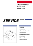
CONTENTS
1. Precautions
2. Specifications
3. Disassembly and Reassembly
4. Troubleshooting
5. Exploded Views and Parts List
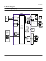
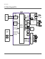
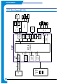
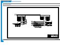
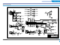
6. Block Diagram
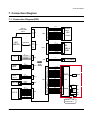
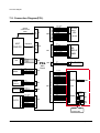
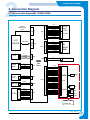
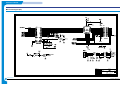
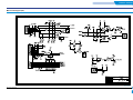
7. Connection Diagram
This service manual is also provided on the web,
the ITSELF system Samsung Electronics Co., Ltd.
http://itself.sec.samsung.co.kr
© Samsung Electronics Co.,Ltd. October. 2001
Printed in Korea.
VERSION NO. : 2.03
CODE : JC-0051A
This manual is stated and
provided for service description.
All rights reserved. Any parts of the
information in this manual are prohibited
from free duplication, use or translation
without prior written approval except in
cases allowed by the Copyright Act.
Specifications are subject to change without
prior notice.
Samsung Electronics Digital Printing CS Group
Copyright (c) 2001. 5.
Precautions
1. Precautions
Please read the following carefully to prevent any accidents and not to damage the unit during service.
1-1 Safety Precautions
1. Safety Precautions
There are some electric or machinery parts with
safety related property. If the parts replaced are different from the original, the safety may not function.
Even if the part could allow higher voltage than that
of the part used, do not replace it and use a regular
product clarified in specifications.
2. Be careful not to leave a switch, a cover or a safety
device out when reinstalling or assembling the product after repair.
3. Replacing Precautions
Do not change or add parts as you like. You cannot
benefit from such a remodeled product at your will
during the term of guarantee.
4. You must replace overheated or damaged parts or
cords with regular products. Please solve the problem causing any damage or overheating and troubles
beforehand.
Especially mind the safety on the part with
this mark.
You must use regular parts described in specifications for the parts inflammable and where the
current can be flown. Otherwise any hazard
such as an electric shock or a fire could occur.
LASER STATEMENT (LASERTURVALLISUUS)
WARNING : NEVER OPERATE AND SERVICE THE PRINTER
WITH THE PROTECTIVE COVER REMOVED
FROM LASER/SCANNER ASSEMBLY. THE
REFLECTIVE BEAM, ALTHOUGH INVISIBLE, CAN
DAMAGE YOUR EYES.
Class 1 laser product
Luokan 1 laserlaite
Klass 1 laser apparat
Allonpituus 770-795nm
Teho 0.3mW±0.03mW
CAUTION
INVISIBLE LASER RADIATION WHEN
THIS COVER OPEN. DO NOT OPEN
THIS COVER.
VORSICHT
UNSICHTBARE LASERSTRAHLUNG,
WENN ABDECKUNG GEOFFNET.
NIGHT DEM STRAHL AUSSETZEN.
ATTENTION
REYONNEMENT LASER INVISIBLE EN CAS
D’OUVERTURE. EXPOSITION DANGERUSE AU
FAISCEAU.
ATTENZIONE
RADIAZIONE LASER INVISIBLE IN CASO DI
APERTURA. EVITARE L’ESPOSIZONE LA FASCIO.
PRECAUCION
REDIACION LASER INVISIBLE CUANDO SE
ABRE. EVITAR EXPONERSE AL RAYO.
CAUTION : Avoid exposure to invisible laser radiation when the
development unit is not installed.
1-2 Precautions on Disassembly and Reassembly
Very careful precautions should be taken when replacing
parts. Before replacing, please check cables because
you cannot put the cables that you removed for replacing
parts into the proper place if you would not make sure of
where they were connected and in which condition.
7. When disassembling, assembling, also observe small
components are located in place.
8. If you uncover and turn the machine over to replace
some parts, toner or paper particles may contaminate
the LSU window. Protect the LSU window with clean
paper.
Please do the following before disassembling for a repair
or replacement of parts.
Releasing Plastic Latches
1. Pull out paper cassette, printer cartridge installed.
Especially careful not to be scratched by the surface of
developer or not to expose them to light.
2. Turn the power switch off.
3. Take out the power plug, printer cable from the printer.
4. Use only the same type of part as original when replacing parts.
5. Do not force to open or fasten plastic material components.
6. Be careful that small parts such as screws should not
get in the printer.
Samsung Electronics
Many of parts are held in
place with plastic latches.
The latches break easily :
release them carefully.
To remove such parts,
press the hook end of the
latch away from the part to
which it is latched.
1-1
Precautions
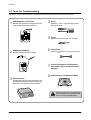
1-3 Tools for Troubleshooting
The following tools are recommended for safe and smooth troubleshooting described in this service manual.
1 DCU(Diagnostic Control Unit)
Standard: Test equipment to diagnose the Laser
printer supplied by Samsung Electronics.
4 Driver
Standard: "-" type, "+" type (M3 long, M3 short,
M2 long, M2 short).
5 Pinset
Standard: For general home use, small type.
2
DVM(Digital Volt Meter)
Standard: Indicates more than 3 digits.
6 Cotton Swab
Standard: For general home use, for medical service.
Ground
Equipments a IPA(Isopropyl
7 Cleaning
Alcohol)dry cloth or a soft stuff neutral
detergent.
3 Electronic Scale
8 Software(Driver) installation CD ROM
Standard: Equipment to check the weight of consumables(toner cartridge) supplied by Samsung
Electronics. (The gram unit can be measured.)
Note
1-2
Mind your hands not to be touched when
you disassemble and reassemble PBA ASS'Y,
such as the main board, SMPS, HVPS.
Samsung Electronics
Specifications
2. Specifications
ML-1210 (ML-1220M)
Engine
Speed
Resolution
12ppm
600 x 600 dpi
1200 x 600 dpi
FROP(Fist Power On Time)
Under 12.5 sec
Warm-Up Time
Power Consumption
Dimension
Weight
Controller
ML-1250
30 sec
25W (Print), 10W (Sleep)
329 x 355 x 231 mm (13” x 14” x 9.1”)
Max 6.5Kg (With Toner Cartridge)
Processor
Jupiter 366MHz
61200 66MHz
Memory
8MB Equivalent
4MB
SmartGDI
PCL6
Emulation
Interface
OS Support
IEEE1284, USB (ML-1220M : USB ONLY)
Windows 95/98/2000/Me/NT,
Linux(Radhat 6.0), iMac(Mac OS 8.0)
Paper
N/W
External
Input
150 sheets
Output
100 sheets
Manual
1 sheet
Media Type
A4, Letter. Legal, Executive, B5, A5, Folio,
7 3/4(Monarch), #10, DL, C5, C6, B5
Toner
Type
Single Cartridge
Life
2,500 sheets
Cartridge
User interface
Pick up Roller
60,000
Feed Roller
60,000
Transfer Roller
60,000
Fuser
40,000
Key & LED
LCD
Samsung Electronics
2,500 (Initial : 1,000)
3Key, 4LEDs
No
Toner Save
YES
Reprint
YES
2-1
Disassembly and Reassembly
3. Disassembly and Reassembly
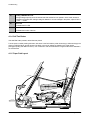
3-1 Cover Assembly
3-1-1 Front Cover
1. Pull the both side of the cover to open.
4. Remove a screw of the front cover PCB and remove
the connector, then remove the cover.
2. Remove a screw and remove the stopper that holds
the printer cover.
3-1-2 Other Covers
1. Before you remove other covers, you should remove the
Front cover in advance.
2. Rear Cover : Remove the cover in the direction of a .
3. Top Cover : Remove the cover in the direction of b .
4. Side Cover L, R : Remove the cover in the direction of c .
3. Loosen the right lower part of the cover, then push the
cover in the direction of arrow to loosen the left lower
part.
Samsung Electronics
3-1
Disassembly and Reassembly
3-2 LED Panel PBA
1. Before you remove other covers, you should remove.
3. Remove two screws, and remove LED panel.
• Front Cover (see [3-1 Main Cover])
2. Remove two screws of PCB cover, and widen the
hooks( a b c ) to remove.
4. Remove PCB from the PCB cover.
3-3 LSU(Laser Scanning Unit)
1. Before you remove LSU, you should remove front
cover, rear cover and top cover.
3. Remove two connectors from the LSU, then remove
the LSU.
• Main Cover (see [3-1 Main Cover])
2. Remove three screws securing the LSU.
3-2
Samsung Electronics
Disassembly and Reassembly
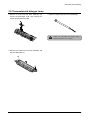
3-4 Transfer Roller
1. Open the front cover.
2. Use a proper tool("-" type screwdriver) to pull the one
end of the roller slightly, then take it out.
3-5 Motor Assembly
1. Before you remove the motor assembly, you should
remove:
• Main Cover (see [3-1 Main Cover])
• Shield Engine Assembly
2. Remove five screws securing the motor assembly
and remove a connector from engine board(Engine
board and SMPS board are integrated), then take the
motor assembly out.
Samsung Electronics
3-3
Disassembly and Reassembly
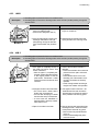
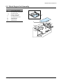
3-6 HVPS Board
1. Before you remove HVPS board, you should remove:
•Main Cover (see [3-1 Main Cover])
2. Remove four screws and a connector from HVPS
board, then take the board out.
Note
When you reassemble the HVPS board, make
sure that five terminals should be put in place.
Terminal
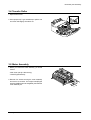
3-7 Fuser Assembly
1. Before remove fuser assembly, you should remove:
• Main Cover (see [3-1 Main Cover])
3. Remove two screws and unplug a fuser assembly
harness. Then use a " - " screwdriver to unlatch the
fuser assembly to remove.
2. Remove two ground screws and a connector as illustrated.
3-4
Samsung Electronics
Disassembly and Reassembly
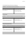
3-8 Thermostat and Halogen Lamp
1. Remove a screw from the fuser assembly and
remove the thermostat cover, then remove two
screws securing the thermostat.
3. Take the halogen lamp out from the Heat Roller.
Note
When you reassemble the halogen lamp,
handle it with care as it is fragile.
2. Remove two screws from the fuser assembly, and
take the Heat Roller out.
Samsung Electronics
3-5
Disassembly and Reassembly
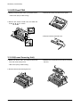
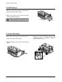
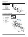
3-9 SMPS Board
1. Before you remove the SMPS board, you should
remove:
• Main Cover (see [3-1 Main Cover])
3. Unplug connectors from the main board and connectors from SMPS, then remove the SMPS. Remove
four screws from SMPS and remove the SMPS
board.
2. Remove screws in the order of a b then remove
the shield engine assembly.
a
b
3-6
Note
The Engine board and SMPS board are
integrated in a body.
Samsung Electronics
Disassembly and Reassembly
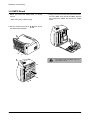
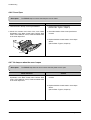
3-10 Main Board and Sensor Board
1. Before you remove the main board, you should
remove:
3. Release four snap-fits securing the insulator engine
board and then remove the insulator.
• Main Cover (see [3-1 Main Cover])
• SMPS board (see [3-9 SMPS Board])
2. Remove two screws from the main board and unplug
all of connectors, then remove the board.
Main B’d
4. Release four snap-fits securing the sensor board and
then remove the sensor board.
Samsung Electronics
3-7
Troubleshooting
4. Troubleshooting
4-1 How to use DCU
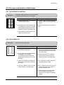
4-4 The cause and solution of the malfunction
4-1-1 DCU Setup ......................................Page(4-2)
4-4-1 All LEDs blinking (Fuser Error)........Page(4-16)
4-1-2 Code ................................................Page(4-2)
4-4-2 All LEDs blinking (SCAN ERROR) .Page(4-16)
4-1-3 Self Diagnostic Mode......................Page(4-3)
4-1-4 Self Test Button ................................Page(4-4)
4-4-3 Not function of the gear of the fuser due to
melting away.....................................Page(4-17)
4-1-5 Paper Path Layout ...........................Page(4-4)
4-4-4 Paper Empty.....................................Page(4-17)
4-4-5 Paper Empty without indication.......Page(4-17)
4-4-6 Cover Open ......................................Page(4-18)
4-2 The cause and solution of Bad image
4-2-1 Vertical Black Line and Band ..........Page(4-5)
4-2-2 Vertical White Line ...........................Page(4-5)
4-2-3 Horizontal Black Band .....................Page(4-6)
4-2-4 Black/White Spot..............................Page(4-6)
4-4-7 No lamp on when the cover is open
...........................................................Page(4-18)
4-4-8 Defective motor operation ...............Page(4-19)
4-4-9 No Power..........................................Page(4-19)
4-4-10 Vertical Line Getting Curved .........Page(4-20)
4-2-5 Light Image.......................................Page(4-7)
4-2-6 Dark Image or a Black.....................Page(4-7)
4-2-7 Uneven Density................................Page(4-8)
4-2-8 Background ......................................Page(4-8)
4-2-9 Ghost (1)...........................................Page(4-9)
4-2-10 Ghost (2)..........................................Page(4-9)
4-2-11 Ghost (3) ..........................................Page(4-10)
4-2-12 Ghost (4) .........................................Page(4-10)
4-2-13 Satins on the Face of Page............Page(4-10)
4-5 Toner Cartridge Service
4-5-1 Precautions on Safe-keeping of Toner Cartridge
..........................................................Page(4-21)
4-5-2 Service for the Life of Toner Cartridge
..........................................................Page(4-21)
4-5-3 Service for Judgement of Inferior Expendables
and the Standard of Guarantee .....Page(4-21)
4-5-4 Signs and Measures at Poor toner cartridge
..........................................................Page(4-22)
4-2-14 Satins on Back of Page..................Page(4-11)
4-2-15 Blank Page Print out (1) .................Page(4-11)
4-2-16 Blank Page Print out (2) .................Page(4-11)
4-6 The cause and solutions of bad environment
of the software
4-6-1 The printer is not working (1)...........Page(4-25)
4-3 The cause and solution of the bad discharge
4-6-2 The printer is not working (2) .........Page(4-26)
4-3-1 Wrong Print Position .......................Page(4-12)
4-6-3 Abnormal Printing.............................Page(4-27)
4-3-2 JAM 0...............................................Page(4-12)
4-6-4 SPOOL Error ...................................Page(4-28)
4-3-3 JAM 1...............................................Page(4-13)
4-3-4 JAM 2...............................................Page(4-13)
4-3-5 Multi-Feeding...................................Page(4-14)
4-3-6 Paper rolled in the fuser .................Page(4-14)
4-3-7 OPC .................................................Page(4-15)
Samsung Electronics
4-1
Troubleshooting
4-1 How to use DCU
4-1-1 DCU Setup
You can examine the malfunction of the printer. To perform DCU, open the front discharge cover and leave the connect
the harness wire(10 pin/4 pin) to the CN10(4 pin) of the Main control board.
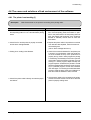
4-1-2 Code
Connect DCU to the printer and turn the power on. It show 7 LED on the panel and each code tells the function of the
printer.
Normal Code
While printing or warming up, it indicate the position of the paper
61
00-05
Warm up
Ready(kind of paper)
20
30
40
50
69
Print Start
Feed Sensor On
Feed Sensor off
Paper Out
Sleep Mode
The printer is on, the cover is open or close.
The printer is ready, the paper is detected when the first paper is printed.
00: Legal , 01: Letter , 02: A4 , 03: EXEC , 04: B5 , 05: Folio
The engine controller received the print order from the video controller.
The paper is passing out of the Feed Sensor.
The paper has passed out of the Feed Sensor.
The paper has passed out of Exit Sensor.
The fuser power turned off to minimize the power consumption.
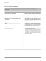
Error Code
When detecting the malfunction, the printing is stopped to indicate error code.
60, 62, 68
Fuser Error
64
70
71
72
73
95
Cover Open
No Paper
Paper Jam 0
Paper Jam 1
Paper Jam 2
LSU Not Ready
4-2
The error in the fuser occurred. There is a short circuit in the thermistor and the
thermostat while printing, Low Temperature Error occurs.
• 60: Open Fuser Error
• 62: Low Heat Error
• 68: Over Heat Error
The Printer Cover is open or Toner Cartridge not installed.
No paper in the paper cassette.
The front part of paper is jammed between pickup unit and Feed sensor.
The front part of paper is jammed between the Discharge sensor and Feed sensor.
The front part of paper is jammed just after passing through the discharge sensor.
LSU Scanner Motor not ready or Hsync signal not output.
Samsung Electronics
Troubleshooting
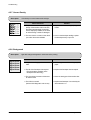
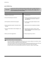
4-1-3 Self Diagnostic Mode
If Error code occurs due to malfunction of the printer, perform Self Diagnostic Mode to solve the problem.
The printer works only in the self-test mode to solve the malfunction problem.
To enter the self-test mode, turn the power on pressing the buttons of [Down], [Shift] and [Stop] at the same time.
Release the button within 2 or 3 seconds if 78 shows in the DCU. If 00 shows in the DCU, press the button [Up] or [Shift]
to select the self+test , and press the button of [Enter] to operate. To stop, press the button of [shift] and [Enter] together.
00
Main Motor Operating System
Only the main motor is in operation.
01
Main High Voltage On(THV-)
-1550 voltage output by MHV terminal.
02
Transfer High Voltage(-)On(THV-)
-1300 voltage output by MHV terminal.
03
Caution : High voltage probe should be used.
Transfer High Voltage (+)Reference on (THV +)
1300 voltage output by MHV terminal.
04
Caution : High voltage probe should be used.
Caution : High voltage probe should be used.
DEV/supply High Voltage : DEV/Supply High Voltage Test.
The left one of the three LEDs in the self-test panel is on when DEV high voltage Supply high voltage output
by each HV terminal. Press the [Up] button to switch the voltage. The middle and right one of the three LEDs
are on and -530 voltage output by DEV HV terminal.
Caution : High voltage probe should be used.
05
LSU Operating System
The scanning motor of LSU is in operation, the right LED of the three buttons on. Press the [Up] button to
Check LD. LD is functioning and the middle button is on. If the LD is normal, all LEDs are on.
06
Pickup clutch on
The Solenoid in the printer is in operation. To stop the operation, Press the button [shift] and [Enter] together.
07
Pempty/PWIDTH/New CRU Sensor Test : Pempty/PWIDTH.HEW CRU sensor test.
If activate the Actuator of the PEMPTY/PWIDTH Sensor, the left and right of the three LEDs are on.
If you install new toner Cartridge in this mode, the right LED is on.
08
Feed & Exit Sensor Test
Test the Feed sensor and Discharge sensor in the same way as '06'.
09
Cover Open Sensor Test
The same way as code '06'.
10
Fuser Test
If the [Enter] button pressed, the right LED is on and temperature of the fuser is up to READY Mode. If the
[Up] button pressed, the middle LED is on and temperature of the fuser is up to Printing Mode.
If you press the button once more, the left LED is on and temperature of the fuser is up to overheat Mode.
11
Hot Burn Test
If the [enter] button pressed, the printer is continuously printing without detection. Turn the power off to stop
operation.
12.
Cleaning Mode Print Mode
Print the paper to clean the OPC Drum in the Cartridge.
Samsung Electronics
4-3
Troubleshooting
13.
THV(+) TRIGGER. ALL HV
All high voltage output by each HV terminal and LSU and the fan is in operation. In this mode, electronic
resistance of transfer roller and high voltage is detected. If no toner cartridge in the printer, output of THV is
+199V ~ + 2100V.
14.
PTL Test
Indicates the PTL LED.
15.
Fan Test
Indicates the function of the fan.
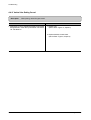
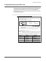
4-1-4 Self Test Button
If the Self-Test button pressed, vertical lines are printed.
Turn the power on while pressing this button, '89' shows in the DCU and the printer is warming up. After warming-up the
printer is in READY Mode, and '88' shows in the DCU. In this mode, without any detection, the printer begins
printing(trial printing and data from the PC). It is convenient to use this mode when the engine malfunction is detected in
the control board.
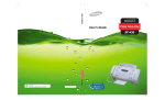
FACE DOWN
PAP
ER
(150
SHE
ETS
)
REC
ORD
ED
MANUA
L 1 SHE
ET
RE
CO
RD
ED
PAP
ER
(10
0S
HE
ETS
)
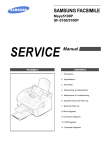
4-1-5 Paper Path Layout
LSU
KNOCK UP
EXIT 2
PICK UP
CARTRIDGE
CR
DR
FUSER
H R/L
SR
OPC
IDLE
FEED
FACE UP
TR
PTL
EXIT 1
SENSOR BOARD
MAIN BOARD
Pr R/L
EXIT SENSOR
SMPS
SHIELD
4-4
EMPTY SEN
FEED SEN
SHIELD
Samsung Electronics
Troubleshooting
4-2 The cause and solution of Bad image
4-2-1 Vertical Black Line and Band
• Description
Digital Printer
Digital Printer
Digital Printer
Digital Printer
Digital Printer
1. Straight thin black vertical line occurs in the printing.
2. Dark black vertical band occur in the printing.
Check and Cause
Solution
1. Damaged develop roller in the Developer
or deformed Doctor-blade.
1. If causes 1 and 2 occur in the developer
cartridge, replace the developer and try to
print out.
2. Scratched surface of the discharge roller
in the developer, or heavily accumulated
foreign matters between the discharge
roller and fur transfer roller/ charge roller.
2. Replace the transfer roller if occurred as
No. 3.
3. Partly depression or deformation on the
surface of the transfer roller.
4-2-2 Vertical White Line
• Description
Digital Printer
Digital Printer
Digital Printer
Digital Printer
Digital Printer
White vertical voids in the image.
Check and Cause
1. Foreign matter stuck onto the window of
internal lenses of LSU mirror.
2. Foreign matter or toner particles between
the developer roller and blade.
(In case the life of the developer has
been expired, white lines occur in front of
the image.)
Solution
1. Foreign matter stuck onto the window :
Clean the LSU window with recommended cleaner(IPA) Clean the window with a
clean cotton swab.
2. Foreign matter in the LSU : Open the
cover of LSU and clean with a cotton
swab on the surface of the reflex mirror.
3. It may occur when Burr and foreign substances are on the window of the developer frame.
3. No 3. : Remove the foreign matter and
burr of the exposure window.
4. If the fuser is defective, voids occur periodically at the top of a black image.
4. No. 4. : Open the front cover and check
ribs that corresponds to the position of
the voids. Remove if found.
5. If the problems are not solved, check to
see if the weight of the developer is
below 670g. If so, replace the developer
cartridge.
Samsung Electronics
4-5
Troubleshooting
4-2-3 Horizontal Black Band
• Description
Digital Printer
Digital Printer
Digital Printer
Digital Printer
Digital Printer
1. Dark or blurry horizontal stripes occur in the printing periodically.
(They may not occur periodically.)
Check and Cause
Solution
1. Bad contacts of the voltage terminals to
developer.
1. Clean each voltage terminal of the Charge,
Supply, Develop and Transfer roller.
(remove the toner particles and paper particles)
2. The rollers of developer may be stained.
Charge roller = 37 mm
Supply roller = 27 mm
Develop roller = 32 mm
Transfer roller = 47 mm
2. Clean the right Gear that has relatively
small gap of the teeth in the OPC.
3. If the malfunction persists, replace the
developer.
4-2-4 Black/White Spot
• Description
Digital Printer
Digital Printer
Digital Printer
Digital Printer
Digital Printer
1. Dark or blurry black spots occur periodically in the printing.
2. White spots occur periodically in the printing.
Check and Cause
Solution
1. If dark or blurry black spots occur periodically, the rollers in the Developer may be
contaminated with foreign matte or paper
particles.
( Charge roller : 37 mm interval
OPC drum : 75mm interval)
1. Run OPC cleaning Mode Print and run the
Self-test 2 or 3 times.
2. If faded areas or voids occur in a black
image at intervals of 75 mm, or black
spots occur elsewhere, the OPC drum
surface is damaged.
2. In case of 75mm interval unremovable in 1,
cleanly remove foreign substances stuck on
the OPC location equivalent to black spots
and white spots with a dry duster.
3. If a black image is partially broken, the
transfer voltage is abnormal or the transfer roller's life has expired.
3. The transfer roller guarantees 50,000
sheets printing. If the roller's life is expired,
replace it.
4. In case of 37mm interval unremovable in 1,
take measures as to replace the developer
cartridge and try to print out.
5. Clean the inside of the set against the paper
particles and foreign matter in order not to
cause the trouble.
4-6
Samsung Electronics
Troubleshooting
4-2-5 Light Image
• Description
Digital Printer
Digital Printer
Digital Printer
Digital Printer
Digital Printer
The printed image is light, with no ghost.
Check and Cause
Solution
1. Develop roller is stained when the toner
of developer cartridge is almost consumed.
1. Check if the Toner Save mode is off.
2. Ambient temperature is below than 10°C.
2. Replace the developer cartridge and try to
print out.
3. Wait 30 minutes after printer is powered on
before you start printing.
3. Bad contact caused by the toner stains
between the high voltage terminal in the
HVPS and the one in the set.
4. Clean up the contaminated area by the
toner.
4. Abnormal output from the HVPS.
(Run self-test and check 1~4)
5. Replace the HVPS if the problems are not
solved by the above four directions.
( Service parts : Figure 11, Chapter 5)
4-2-6 Dark Image or a Black
• Description
Digital Printer
Digital Printer
Digital Printer
Digital Printer
Digital Printer
The printed image is dark.
Check and Cause
Solution
1. No charge voltage in the engine board.
( Perform DCU diagnostic code 01)
1. Clean the high voltage charge terminal.
2. Charge voltage is not turned on due to
the bad contacts between power supply
in the side of the Developer and charge
terminal of HVPS.
2. Check the state of the connector which
connects the engine board and HVPS.
3. Replace the HVPS if not solved by the
above direction 1 and 2.
Samsung Electronics
4-7
Troubleshooting
4-2-7 Uneven Density
• Description
Print density is uneven between left and right.
Check and Cause
Solution
1. The pressure force on the left and right
springs of the transfer roller is not even,
the springs are damaged, the transfer
roller is improperly installed, or the transfer roller bushing or holder is damaged.
1. Replace both the left and right Spring
Holder.
2. The toner level is not even on the developer roller due to the bad blade.
2. Occur in the developer cartridge, replace
the developer and try to print out.
4-2-8 Background
• Description
Digital Printer
Digital Printer
Digital Printer
Digital Printer
Digital Printer
4-8
Light dark background appears in whole area of the printing.
Check and Cause
Solution
1. Recycled recording paper has been
used.
1. B/S is not guaranteed when using recycled
paper.
2. The life of the Developer has expired.
(The weight at the expiration of the
developer's life: 800 ± 20g)
2. Replace the Developer that has expired.
3. The up-to-down movement of the transfer roller is swift?
3. Clean the busing part of the transfer roller.
4. The HVPS is normal?
(Perform DCU diagnostic code 01~04)
4. Replace the Developer if not solved by the
above direction 1~3.
Samsung Electronics
Troubleshooting
4-2-9 Ghost (1)
• Description
75mm
Digital Printer
Digital Printer
Digital Printer
Digital Printer
Digital Printer
Digital Printer
Ghost occurs at 75 mm intervals of the OPC drum in the whole printing.
Check and Cause
Solution
1. Bad contacts caused by contamination
from toner particles between high voltage
terminal in the main body and the electrode of the Developer.
1. Clean the terminals when contaminated by
toner particles.
2. Bad contacts caused by contamination
from toner particles between high voltage
terminal in the main body and the one in
the HVPS board.
2. Occur in the developer cartridge, replace
the developer and try to print out.
3. The life of developer is expired.
3. Replace the engine board if not solved by
the above directions 1-2.
(Service Parts : Figure 9 , chapter 5)
4. Transfer roller lifetime(50,000 sheets) has
expired.
4. If not solved by the direction 3, check the
transfer roller lifetime and replace it.
(Service Parts : Figure 8-2 , chapter 5)
5. Abnormal low temperature(below 10°C).
5. Wait about 1 hour after power on before
using printer.
4-2-10 Ghost (2)
• Description
Samsung Electronics
75mm
Digital Printer
Digital Printer
Digital Printer
Digital Printer
Digital Printer
Digital Printer
Ghost occurs at 75 mm intervals of the OPC drum in the whole printing.
(When printing on card stock or transparencies using manual feeder)
Check and Cause
Solution
When printing on card stock thicker than normal paper or transparencies such as OHP,
higher transfer voltage is required.
Select 'Thick Mode' on paper type menu from
the software application and after using returning to the original mode is recommended.
4-9
Troubleshooting
4-2-11 Ghost (3)
• Description
Check and Cause
Digital
Digital Printer
Printer
Solution
1. The life of the developer may be expired.
1. Occur in the developer cartridge, replace
the developer and try to print out.
2. The abnormal voltage and bad contact of
the terminal of the supply roller
roller.
2. Check the approved voltage of the supply
roller and contact of the terminal and adjust
if necessary.
32mm
Digital
Digital Printer
Printer
Digital
Digital Printer
Printer
White ghost occurs in the black image printing at 32mm intervals.
4-2-12 Ghost (4)
• Description
Check and Cause
47mm
Digital Printer
Digital Printer
Digital Printer
Digital Printer
Digital Printer
Digital Printer
Ghost occurs at 47mm intervals.
The temperature of the fuser is maintained
high.
Solution
1. Disassemble the fuser and remove the
contaminated toner particles on the roller
and clean the foreign matter between
Thermistor and Heat roller.
(
Caution: can be deformed)
4-2-13 Satins on the Face of Page
• Description
Digital Printer
Digital Printer
Digital Printer
Digital Printer
Digital Printer
4-10
The background on the face of the printed page is stained.
Check and Cause
Solution
1. Toner leakage due to improperly sealed
developer.
1. Replace the developer cartridge.
2. If the transfer roller is contaminated, satins
on the face of page will occur.
2. If the transfer roller is contaminated, run PC
Cleaning Mode Print 2 or 3 times.
And perform Self-Test 2 or 3 times to
remove contamination.
Samsung Electronics
Troubleshooting
4-2-14 Satins on Back of Page
• Description
Digital
Digital Pri
Digital Printer
Digital Printer
Digital Printer
The back of the page is stained at 47mm intervals.
Check and Cause
Solution
1. Transfer roller is contaminated.
1. Perform the OPC Cleaning Mode Print 2 or
3 times. Run Self-Test to remove the contamination of the transfer roller.
2. Pressure roller is contaminated.
2. Replace the transfer roller if contaminated
severely.
3. Disassemble the fuser and clean the
H/R(Heat Roller) and P/R(Pressure roller).
And check the area between H/R and
Thermistor. If contaminated, clean the area
not to be deformed.
4-2-15 Blank Page Print out (1)
• Description
Digital Printer
Digital Printer
Digital Printer
Digital Printer
Digital Printer
Blank page is printed.
Check and Cause
Bad ground contacts in OPC and/or developer.
Solution
Remove contamination of the terminals of the
developer and the unit.
4-2-16 Blank Page Print out (2)
• Description
1. Blank page is printed.
2. One or several blank pages are printed.
3. When the printer turns on, several blank pages print.
Check and Cause
Solution
1. Bad ground contacts in OPC and/or
developer.
1. Remove contamination of the terminals of
the developer.
2. Abnormal solenoid.
2. Perform the engine self test using DCU to check
if the Solenoid is normal.(refer to code 06)
3. If not solved by the above directions 1-2,
Replace the engine board.
(Service Parts : Figure 9 , chapter 5)
4. Turn the power off, delete the data of PC
and try printing again.
Samsung Electronics
4-11
Troubleshooting
4-3 The cause and solution of the bad discharge
4-3-1
Wrong Print Position
• Description
Printing begins at wrong position on the paper.
Check and Cause
Solution
Wrong sense time caused by defective feed sensor
actuator.
Replace the defective actuator
(Service Parts : Figure 8-16 , chapter 5)
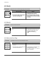
4-3-2 JAM 0
1. Paper is not exited from the cassette.
2. Jam-0 occurs if the paper feeds into the printer.
• Description
Check and Cause
Solution
1. Check the Solenoid by using DCU
diagnostic mode 06.
1. Replace the solenoid. (Service Parts :
Figure 8-11 , chapter 5)
2. Check if the pad is loose due to bad
sealing of the side-pad.
2. Replace the side-pad Assembly L or
R, if necessary.
(Service Parts : Figure 8-13 , 8-14,
chapter 5)
LSU
EXIT 2
PICK UP
CARTRIDGE
FEED SEN
EXIT 1
EXIT SENSOR
JAM 0
3. Check the surface of the roller-pickup for foreign matter.
4. If continuous clusters occur, check
whether the assembly slot between
shaft-pickup and housing-pickup
become open or is broken away.
3. Clean with soft cloth dampened with
IPA(Isopropyl Alcohol) or water.
4. Replace the Housing-Pickup and/or
Shaft-Pickup.
(Service Parts : Figure 8-135, 8-12, chapter 5)
5. If the paper feeds into the printer
rand Jam 0 occurs, perform DCU to
check feed-sensor of the sensor
board.
4-12
Samsung Electronics
Troubleshooting
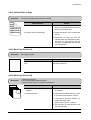
4-3-3
JAM 1
1. Recording paper is jammed in front of or inside the fuser.
2. Recording paper is stuck in the discharge roller and in the fuser just after passing through the
Actuator-Feed.
• Description
Check and Cause
LSU
EXIT 2
Solution
1. If the recording paper is jammed in
front of or inside the fuser.
(Perform DCU diagnostic code of)
1. Replace the SMPS. (Service Parts :
Figure 10, chapter 5)
2. If the recording paper is stuck in the
discharge roller and the fuser just
after passing through the ActuatorFeed, Feed Actuator may be defective.
2. Reassemble the Actuator-Feed and
Spring-Actuator if the returning is bad.
PICK UP
CARTRIDGE
FEED SEN
FEED
EXIT 1
EXIT SENSOR
JAM 1
4-3-4 JAM 2
1. Recording paper is jammed in front of or inside the fuser.
2. Recording paper is stuck in the discharge roller and in the fuser just after passing through the
Actuator-Feed.
• Description
LSU
EXIT 2
PICK UP
CARTRIDGE
FEED SEN
EXIT 1
EXIT SENSOR
JAM 2
Samsung Electronics
Check and Cause
Solution
1. If the paper is completely fed out of
the printer, but Jam 2 occurs : Exit
sensor is defective.
• After the paper is completely discharged, actuator Exit should return
to the original position to shut the
photo-sensor. Sometimes it takes
longer hour than it should and does
not return.
1. Check if the exit sensor actuator is
defective.
• Check if the actuator exit is unformed
(Check if the lever part is unformed
in shape).
• Check whether burrs occur in the
assembly part of the actuator exit or
not and if the actuator is smoothly
operated.
• Check if foreign matters and wire get
caught in the actuator exit's operation.
2. If the paper is rolled in the Fuser Roller:
• This occurs when a Guide claw is
broken away or transformed.
• It occurs when the Spring of a Guide
claw is broken away or transformed.
• It occurs when the Heat-Roller or
Pressure-Roller is seriously contaminated with the toner.
2. If the paper is stuck in the fuser : disassemble the fuser and remove the
jammed paper, and clean the surface
of the pressure roller with dry gauze.
3. Paper is accordion in the fuser.
3. Remove the jammed paper after disassembling the fuser : Clean the surface
of the pressure roller with dry gauze.
• Remove the toner particles stained
on the rib.
• Check the assemblage and performance of the exit.
4-13
Troubleshooting
4-3-5 Multi-Feeding
• Description
Multiple sheets of paper are fed at once.
Check and Cause
Solution
1. Solenoid malfunction(the solenoid does not work
properly): Perform DCU mode : solenoid check 06.
1. Replace the solenoid if necessary.
(Service Parts : Figure 13, chapter 5)
2. Pad-Friction is contaminated with foreign matter.(oil...)
2. Clean the pad friction with soft clothe dampened
with IPA(Isopropyl Alcohol).
3. The face of paper is blended.
3. Use the smooth paper.
4-3-6 Paper rolled in the fuser
• Description
If contaminated at intervals of 57mm on the back of a paper.
Check and Cause
1. Contamination of the pressure roller.
(Background, Hot off set)
Solution
1. Disassemble the fuser, clean the area between the
Heat-roller and Thermistor and remove the foreign
matter of the pressure roller.
2. If background appears badly in the printing, fix it by
referring to the solutions for background.
(See 4-2-8 Background)
4-14
Samsung Electronics
Troubleshooting
4-3-7
OPC
• Description
Paper is rolled up in the OPC.
Check and Cause
Solution
1. Paper is too much thin.
1. Recommend to use normal paper.
2. The face of paper is curled.
2. How to remove the rolled paper in the OPC.
• Remove the paper while turning the OPC against
the ongoing direction.
• Clean fingerprints on the OPC softly with soft
cloth dampened with IPA(Isopropyl Alcohol) or tissue.
Samsung Electronics
4-15
Troubleshooting
4-4 The cause and solution of the malfunction
4-4-1 All LEDs blinking (Fuser Error)
• Description
1. All the lamps on the operator panel blink.
2. Gear of the fuser does not work and breaks away melt away.
When printing, motor breaks away from its place due to defective fuser gear.
Check and Cause
Solution
1. Check if the thermostat, AC wire and Heat Lamp is
open.
1. If the thermostat is open replace the fuser and
check following items.
2. Check if the thermistor sensor is in place.
2. If the thermistor sensor device is located deep in the
sponge, replace the fuser.
3. Check if the heat lamp works properly.
3. Check if the circuit of overheat mode works properly.
4. Check if the overheat circuit works properly.
4. Run DCU mode : Perform DCU diagnostic code 10.
5. The fuser gear is defective due to melting away.
4-4-2 All LEDs blinking (Scan Error)
• Description
1. All lamps on the operator panel blink.
Check and Cause
DCU Mode : Perform DCU diagnostic code 05. If the DCU
error code 95 is displayed, replace LSU.
Solution
Replace LSU.
(Service Parts : Figure 13, chapter 5)
If you cannot solve the problem after you replace LSU,
replace the main board.
4-16
Samsung Electronics
Troubleshooting
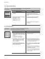
4-4-3 Not function of the gear of the fuser due to melting away
• Description
The motor breaks away from its place due to gear melting away.
Check and Cause
DCU Mode : Check if the Error States '60' '62' '68' occur.
Check the operation of Fuser Erasing Lamp On/Off with
the Error Code Check -10-.
Solution
1. Replace the Fuser.
(Service Parts : Figure 8-4, Chapter 5)
2. Replace the Main Control board.
(Service Parts : Figure 9, Chapter 5)
4-4-4 Paper Empty
• Description
The paper lamp on the operator panel is on even when paper is loaded in the cassette.
Check and Cause
Solution
1. Bending or deformation of the actuator of the paper sensor.
1. Replace the defective actuator.
(Service Parts : Figure 8-17, Chapter 5)
2. The function of the sensor board is defective Perform
DCU mode: Perform DCU diagnostic code 8.
2. Replace the sensor board.
(Service Parts : Figure 8-10, Chapter 5)
4-4-5 Paper Empty without indication
• Description
The paper lamp on the operator panel does not come on when the paper cassette is empty.
Check and Cause
Solution
1. Bending or deformation of the actuator of the paper sensor.
1. Replace the defective actuator.
(Service Parts : Figure 8-17, chapter 5)
2. The function of the sensor board is defective Perform.
DCU mode : Perform DCU diagnostic code 8.
2. Replace the sensor board.
(Service Parts : Figure 8-10, chapter 5)
Samsung Electronics
4-17
Troubleshooting
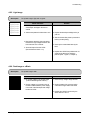
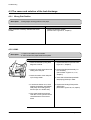
4-4-6 Cover Open
• Description
The ERROR lamp is on even when the print cover is closed.
Check and Cause
Solution
1. The hook lever in the top cover may be defective.
1. Replace the hook lever, if defective.
(Service Parts : Figure 1, chapter 5)
2. Check the connector and circuit of the cover switch
department in the Main Control board. Perform DCU
mode : If Error state '64' occurs, Check the related codes
of the Cover Open Error.
2. Check the insertion of the Cover Open Sensor
Connect.
3. Replace the Main Control board or Cover Open
Sensor.
(Service Parts : Figure 9, chapter 5)
Hook Lever
4-4-7 No lamp on when the cover is open
• Description
The ERROR lamp does not come on even when the printer cover is open
Check and Cause
1. Check the connector(CN8) and circuit of the cover switch
department in the Main Control board. Perform DCU
mode : If Error state '64' occurs, Check the related codes
of the Cover Open Error
Solution
1. Check the insertion of the Cover Open Sensor
Connect.
2. Replace the Main Control board or Cover Open
Sensor.
(Service Parts : Figure 9, chapter 5)
4-18
Samsung Electronics
Troubleshooting
4-4-9 Defective motor operation
• Description
Main motor is not driving when printing, and paper does not feed into the printer, resulting 'Jam 0'.
Check and Cause
Solution
1. Motor harness or sub PCB may be defective.
1. Check the motor harness, replace it, if defective.
(Service Parts : Figure 12, chapter 5)
2. Perform DCU diagnostic code 00 and Check the motor
operation.
2. Replace the SMPS, if necessary.
(Service Parts : Figure 10, chapter 5)
4-4-10 No Power
• Description
When system power is turned on, all lamps on the operator panel do not come on.
Check and Cause
Solution
1. Check if the power input and SMPS output are normal.
1. Replace the power supply cord or SMPS.
(Service Parts : Figure 10, chapter 5)
2. Check the inferiority of LED-Panel on the front-cover if
the LED of Panel does not appear after normal warmingup.
2. Replace the control board.
(Service Parts : Figure 9, chapter 5)
3. Replace the LED-panel.
(Service Parts : Figure 1-1, chapter 5)
Samsung Electronics
4-19
Troubleshooting
4-4-11 Vertical Line Getting Curved
• Description
When printing, vertical line gets curved.
Check and Cause
1. If the supply of +24v is unstable in the Main Control board
linking with LSU, check drive by DCU Mode: LSU Check
-05- LSU Motor on.
Solution
1. Replace LSU.
(Service Parts : Figure 13, chapter 5)
2. Replace the Main Control board.
(Service Parts : Figure 9, chapter 5)
4-20
Samsung Electronics
Troubleshooting
4-5 Toner Cartridge Service
It is not guaranteed for the default caused by using other toner cartridge other than the cartridge supplied by the
Samsung Electronic or caused by non-licensed refill production.
4-5-1 Precautions on Safe-keeping of Toner Cartridge
Excessive exposure to direct light more than a few minutes may cause damage to the cartridge.
4-5-2 Service for the Life of Toner Cartridge
If the printed image is light due to the life of the toner, you can temporarily improve the print quality by redistributing the
toner(Shake the toner cartridge), however, you should replace the toner cartridge to solve the problem thoroughly.
4-5-3 Service for Judgement of Inferior Expendables and the Standard of Guarantee
Please refer to User's Manual or Instructions on Fax/Printer Expendables SVC for the judgement of inferior expendables and the standard of guarantee besides this service manual.
Samsung Electronics
4-21
Troubleshooting
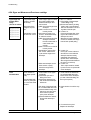
4-5-4 Signs and Measures at Poor toner cartridge
Fault
Light image and
partially blank
image
(The life is ended.)
Digital Printer
Digital Printer
Digital Printer
Digital Printer
Digital Printer
Signs
Cause & Check
• The printed image
is light or unclean
and untidy.
1. If the image is light or unclean
and untidy printed image Shake the developer and
then recheck.
• Some part of the
(1)NG: Check the weight of the
image is not printdeveloper
ed.
(2)OK: Lack of toner, so the life
is nearly closed.
• Periodically a noise 2. Some part of image is not
as "tick tick" occurs.
printed - Shake the developer and then recheck.
(1)NG: Check the weight of the
developer and clean
the LSU window with a
cotton swab, then
recheck.
(2)OK: Lack of toner, so the life
is nearly closed.
3. Periodically a noise as "tick
tick" occurs - Measure the
cycle and the weight of the
developer.
4. White vertical stripes on the
whole screen or partly :
Check the weight of the
developer.
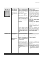
Toner
Contamination
• Toner is fallen on
the papers periodically.
• Contaminated with
toner on prints partly or over the whole
surface.
Solution
1. All of 1, 2, 3 above(1)The weight of the developer
ended: 800g ± 20g
(2)If it become better by shaking,
replace with a new developer
after 50-100 sheets in the closing state of the life span.
2. In case of 2If it becomes better after cleaning the LSU window, then the
developer is normal.
(Because of foreign substance
on the LSU window, the image
has not been printed partly.)
3. In case of 3If the cycle of noise is about 2
seconds, the toner inside the
developer has been nearly
exhausted.( Purchase and
replace with a new developer
after using about 200 sheets at
the point of occurrence)
4. In case of 3This is a phenomenon caused
by lack of toner, so replace with
a new developer.
1. Toner is fallen on the paper
periodically.
(1)Check the cycle of the
falling of the toner.
(2)Check the appearance of
both ends of the developer
OPC drum.
1. If both ends of the OPC drum
are contaminated with toner:
Check the life of the developer.
(In case of less than 820g, the
life may be expired.)
2.The center of the printed matter is contaminated with toner.
(1)Check whether foreign substances or toner are stuck
to the terminal (contact
point) of the developer.
(2)Check whether the state of
the terminal assembly is
normal.
2. Check whether it could be recycled.
3. If it cannot be recycled:
Replace the developer.
4-22
Samsung Electronics
Troubleshooting
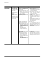
Fault
White Black spot
Digital Printer
Digital Printer
Digital Printer
Digital Printer
Digital Printer
Signs
Cause & Check
1. If light or dark periodical black
dots occur, this is because the
developer rollers are contaminated with foreign substance
or paper particles.
• White spots occur
in the image period- (1)35mm interval : Charged
roller
ically.
(2)75mm interval : OPC cycle
• Light or dark black
dots on the image
occur periodically.
2. If white spots occur in a black
image at intervals of 75mm, or
black spots occur elsewhere,
the OPC drum is damaged or
foreign substance is stuck to
the surface.
Recycled product
Samsung Electronics
Solution
1. In case of 1 above Run OPC Cleaning Mode Print
4-5 times repeatedly to remove.
Especially check foreign substance on the OPC surface, then
remove them with a clean gauze
moistened with IPA(Isopropyl
Alcohol) not to damage OPC if
necessary.
Never use usual alcohol.
2. In case of 2
If they are not disappeared by
running OPC Cleaning Mode
Print 4-5 times.
: at intervals of 37mm - Replace
the developer.
: at intervals of 75mm - Remove
foreign substance.
: Broken image - Replace the
developer according to carelessness.
3. If a black and white or graphic
image is partially broken at
irregular intervals, the transfer
roller's life has been expired or
the transfer voltage is abnormal.
3. In case of 3 - Exchange the
transfer roller because the life of
the transfer roller in use has been
expired. (Check the transfer voltage and readjust if different.)
• Poor appearance of 1. Poor appearance of the develthe developer.
oper.
(1)Check the damage to label
• Unclean and rough
and whether different materiprintouts.
als are used.
(2)Check the appearance of
• Bad background in
parts of the developer, such
the image.
as frame, hopper.
1. In case of 1 (1)If there is an evidence of disassembling the developer.
(2)If materials other than normal
parts of the developer are
added or substituted.
2. Unclean and rough printouts.
(1)Check whether foreign substance or toner are stuck to
the terminal (contact point) of
the developer.
(2)Check whether the state of
the terminal assembly is normal.
2. In case of 2 - If there are any
abnormals in connection with the
situation of 1.
(1)It occurs when the developer
is recycled over 2 times.
(2)If toner nearly being expired
are collected to use, it is
judged as the recycled developer.
4-23
Troubleshooting
Fault
Ghost & Image
Contamination
Signs
Cause & Check
Solution
• The printed image
is too light or dark,
or partially contaminated black.
1. The printed image is too light
or dark, or partially contaminated black.
(1)Check whether foreign substance or toner are stuck to
the terminal(point of contact)
of the developer.
(2)Check whether the terminal
assembly is normal.
1. All of 1, 2, 3 above
(1)Remove toner and foreign substances adhered to the contact
point of the developer.
(2)The contact point of the unit
facing that of the developer
also must be cleaned.
(3)If the terminal assembly is
unsafe:
• Fully stick the terminal to or
reassemble it after disassembling.
• Disassemble the side plate and
push the terminal to be stuck,
then reassemble it.
2. Totally contaminated black.
(Black image printed out)
(1)Check whether foreign substances are stuck to the terminal(point of contact) of the
developer and the state of
assembly.
(Especially check the
charged roller terminal.)
2. In case of 2
It is a phenomenon when the
OPC drum of the developer is not
electrically charged. Clean the
terminals of the charged roller,
then recheck it.
3. The printed image is dark and
ghost occurs.
(1)Check foreign substance
attached to the terminal
(point of contact) of the
developer and the state of
assembly.
(Especially check the developing roller terminal.)
3. In case of 3
It is a phenomenon as the developing bias voltage of the developer. Clean the terminals of the
developing roller, then recheck it.
• Totally contaminatedblack.
(Black image printed out)
• The density of printouts is too dark and
ghost occurs.
4-24
Samsung Electronics
Troubleshooting
4-6 The cause and solutions of bad environment of the software
4-6-1 The printer is not working (1)
• Description
While Power turned on, the printer is not working in the printing mode.
Check and Cause
Solution
1. Run Self-Test Mode: Turn the power on while pressing
the test printing button for 2 or 3 seconds before printing
works.
1.Check the power of the printer and perform the SelfTest. If the test printing works, that means no problems in the printer itself. If the test printing does not
work, that means bad functioning of the printer(not
because of software). Perform DCU to check the
Error Status.
2. Check if the PC and the printer is properly connected
and the toner cartridge installed.
2. Replace the printer cable. If the problems not solved
even after the cable replaced, check the amount of
the remaining tone.
(refer to Toner Cartridge Service 4-5)
3. Printing is nor working in the Windows.
3. Check if the connection between PC and printer port
is proper. If you use windows, check if the printer driver in the controller is set up. If the printer driver is
properly set up, check in which program the printing
is not working. The best way to find out is to open the
memo pad to check the function of printing. If it is not
working in a certain program, adjust the setup the
program requires. Sometimes, the printout is normal
within the Windows basic programs, but it's not working in a particular program. In such case, install the
new driver again. If not working in the Windows basic
program, Check the setup of the port of CMOS is on
ECP. And check the address of IRQ 7 and 378
4. Check if the printer cable is directly connected to peripheral devices
Samsung Electronics
4. If the scanner needs to be connected to the printer,
first the remove the scanner from the PC to see if the
printer is properly working alone.
4-25
Troubleshooting
4-6-2 The printer is not working (2)
• Description
After receiving the printing order, no response at all or the low speed of printing
occurs due to wrong setup of the environment rather than malfunction of the printer itself.
Check and Cause
Solution
1. Secure more space of the hard disk.
1. Not working with the message 'insufficient printer
memory' means hard disk space problem rather than
the RAM problem. In this case, provide more space
for the hard disk. Secure more space using the disk
utilities program.
2. Printing error occurs even if there is enough space in
the hard disk.
2. The connection of the cable and printer port is not
proper. Check if the connection is properly done and
if the parallel port in CMOS is rightly set up.
3. Check the parallel-port-related items in the CMOS
Setup.
3. As a printer port, Select ECP or SPP among
SPP(Normal), ECP, and EPP modes(increase printing speed) SPP normal mode support 8-bit data
transfer, while ECP Mode transfer the 12-bit data.
4. Reboot the system to print.
4. If the regular font is not printing, the cable or the
printer driver may be defective.
Turn the PC and printer off, and reboot the system
to print again. If not solved, double-click the printer in
my computer If the regular fonts are not printed this
time again. the cable must be defective so replace
the cable with new one.
4-26
Samsung Electronics
Troubleshooting
4-6-3 Abnormal Printing
• Description
The printing is not working properly even when the cable has no problem.
(even after the cable is replaced)
If the printer won't work at all or the strange fonts are repeated, the printer driver may be defective or wrong setup in the CMOS Setup.
Check and Cause
Solution
1. Set up the parallel port in the CMOS SETUP.
1. Select SPP(Normal) or ECP LPT Port the among
ECP, EPP or SPP in the CMOS Setup.
2. Printer Driver Error.
2. Check the printer in My Computer.(to see if the
printer driver is compatible to the present driver or
delete the old driver, if defective and reinstall the new
driver)
3. Error message from insufficient memory.
(The printing job sometimes stops or due to insufficient
virtual memory, but it actually comes from the insufficient space of the hard disk.)
3. Delete the unnecessary files to secure enough
space of the hard disk and start printing job again.
Samsung Electronics
4-27
Troubleshooting
4-6-4 SPOOL Error
• Description
To spool which stands for "simultaneous peripheral operations online" a computer document or
task list (or "job") is to read it in and store it, usually on a hard disk or larger storage medium so
that it can be printed or otherwise processed at a more convenient time (for example, when a
printer is finished printing its current document).
Check and Cause
Solution
1. Insufficient space of the hard disk in the directory
assigned for the basic spool.
1. Delete the unnecessary files to provide more space
to start printing job.
2. If the previous printing error not solved.
2. If there are some files with the extension name of
****.jnl, Delete them and Reboot the Windows to
restart printing job.
3. When expected to collide with other program.
3. Shut down all other programs except the current
one, if possible.
4. When an application program or the printer driver is
damaged.
4. Delete the printer driver completely and reinstall it.
5. When some files related to OS are damaged or virus
infected.
5 After rebooting the computer, check for viruses,
restore the damaged files and reinstall the program
to do the printing job.
6. Memory is less than suggested one.
6. Add up enough memory to the PC.
How to delete the data in the spool manager.
In the spool manager, the installed drivers and the list of the documents waiting to be printed are shown.
Select the document to be deleted and check the delete menu.
If you intend to delete the current document being printed, the data being transferred to the printer will be put
out and then the document is removed. Before choosing the document, the menu is still inactive.
Or put the document out of the list and repeat the routine as in the above or finish the spool manager.
4-28
Samsung Electronics
Exploded Views and Parts List
5. Exploded Views and Parts List
• Deal drawings and service parts are declared for the items with higher rate
of inferiority and replaceable in the level of service description only.
• If inferiority occurs, you can replace the parts by the unit declared in deal
drawings and service items.
Way to observe Part Code & Description
Part code and Description is quoted and controlled by determined standard. Refer to this determined
standard, it will help with ordering Part.
• There ar woo kinds of Part code inscription type.
ex ) 2007-007961
R-CHIP
ex ) JB96-01268A
ELA UNIT-COVER TOP
Type 1 : Controlled by Company : It can be commonly used for all kinds of product SEC produce.
Mostly, electronics Parts.
Type 2 : Controlled by Division : It is used or one produce. Mostly, Mostly, mechanical Parts.
• A/S privately used part : It is only used for A/S .
• Ass’y part : Assembled by more than 2 Parts. If necessary part is not A/S Part, Ass’y part including
necessary par can be used. It is shown in the diagram and drawing of SVC manual.
• Ass’y part and A/S privately used Part is distinguished by part Code and Description.
The are inscription type 2. It is recognized by Part character and front side of description.
Samsung Electronics
DIVISION
A/S Private
PART CODE
**81-******
(JB81-00039A)
DESCRIPTION
AS-*****
(AS-USE)
ASS’Y Part
**75-******
(JB75-00068A)
MEC-*****
(MEC-CHUTE)
ASS’Y Part
**92-******
(JB92-01131A)
PBA ******
(PBA MAIN-CONTROLLER)
ASS’Y Part
**97-******
(JB97-01089A)
MEA ******
(MEA UNIT-PULLEY IDLE)
5-1
Exploded Views and Parts List
5-1 Exploded Views and Parts List
• Service Parts List
No.
1
1-1
1-2
1-3
1-4
1-5
1-6
1-7
2
Description
ELA UNIT-CVR FRONT
PBA SUB-LED PANEL
PMO-COVER FRONT
CBF HARNESS-FRONT PANEL
PMO-COVER PCB
PMO-GUIDE STACKER
PMO-STOPPER
PMO-COVER FRONT, SUB IMAC
PMO-STACKER RX
PMO-STACKER RX
3
PMO-COVER TOP
4
PMO-COVER REAR
5
PMO-COVER SIDE(L)
6
PMO-COVER SIDE(R)
7
MEC-TRAY(P)
MEC-TRAY(P)
8
ELA UNIT-FR LOWER
8-1
PMO-FRAME LOWER
8-2
MEC-ROLLER_TRANSFER
8-3
FAN-DC
8-4
ELA HOU-FUSER ASS’Y
ELA HOU-FUSER ASS’Y
8-4-1 LAMP-HALOGEN
LAMP-HALOGEN
8-4-2 THERMOSTAT
8-5
MEC KNOCKUP-ASS’Y
8-6
MEC UNIT HOLDER PAD
8-7
PMO-CAP_PAD
8-8
MEC GEAR-PICK UP
8-9
MEC-TERMINAL
8-10
PBA MAIN-SENSOR
8-11
SOLENOID
8-12
MEC-CAM PICK UP
8-13
MEC-SIDE PAD(L)
8-14
MEC-SIDE PAD(R)
8-15
PMO-HOUSING-PICK UP
8-16
PMO-ACTUATOR-EXIT
8-17
PMO-ACTUATOR-FEED
8-18
MEC-PLATE UPPER
8-19
ELA HOU-OPEN SENSOR
8-20
ELA HOU-PTLASS’Y
8-21
PMO-BUSHING_TR(R)
8-22
PMO-BUSHING_TR(L)
8-23
SPRING-TR, L
8-24
SPRING-TR (300)
8-25
PMO-HOLDER_EXIT
8-26
PMO-COVER PTL
8-27
PMO-BUSHING SHAFT
8-28
MEC-ROLLER FEED
8-29
EMC-HOLDER FEED
8-30
PMO-HOLDER TR
9
PBA MAIN-CONTROLLER GDI
PBA MAIN-CONTROLLER PCL
PBA MAIN-ML-1220M IMAC(SUB)
10
SMPS-ML-1210 V2
SMPS-ML-1210 V1
11
SMPS-HVPS
SMPS-HVPS
12
ELA UNIT-RX DRIVE
12-1
MOTOR-STEP 7.5
13
UNIT-LSU
UNIT-LSU
5-2
O : Service available X : Service not available
SEC.Code
Q’ty SA
*
1
X
JC92-01280A
1
O
refer to the table ⇒ 1
O
JC39-00112C
1
O
JC72-00678A
1
O
JC72-00511A
1
O
JC72-00519A
1
O
JC72-00843A
1
O
JC72-00302A
1
O
JC72-00302C
1
O
JC72-00522A
1
O
JC75-00094A
1
O
JC72-00523A
1
O
JC72-00524A
1
O
JC75-00099A
1
O
JC75-00099D
1
O
*
1
X
JC72-00533A
1
O
JC75-00129A
1
O
3103-001085
1
O
JC81-00424A
1
O
JC81-00423A
1
O
4713-001136
1
O
4713-001135
1
O
4712-000001
1
O
JC75-00053A
1
O
JC97-01486A
1
O
JC72-00124A
1
O
JC75-00056A
1
O
JC75-00049A
5
O
JC92-01197A
1
O
JC33-00002B
1
O
JC75-00072A
1
O
JC75-00050B
1
O
JC75-00051B
1
O
JC72-00109A
1
O
JC72-00130A
1
O
JC72-00119A
1
O
JC75-00111A
1
O
JC96-01584A
1
O
JC96-02037A
1
O
JC72-00101A
1
O
JC72-00102A
1
O
JC61-00458A
1
O
JC61-00024A
1
O
JC72-00532A
1
O
JC72-00534A
1
O
JC72-40849A
1
O
JC75-00054A
1
O
JC75-00055A
1
O
JC72-00100D
1
O
JC92-01316D
1
O
JC92-01333A
1
O
JC92-01316C
1
O
JC44-00026A
1
O
JC44-00025A
1
O
JC44-00024A
1
O
JC44-00036A
1
O
JC96-02125A
1
O
JC31-00005B
1
O
JC59-00015A
1
O
JC59-00015B
1
O
Remark
• PMO-COVER FRONT •
ML-1210
ML-1220M ONLY
ML-1210,1250
ML-1220M
ML-1210,1250
ML-1220M
220V
110V
220V
110V
125 / 250V
ML-1210/XAA
JC72-00677A
ML-1210/XAC
JC72-00677A
ML-1210/XAX
JC72-00677F
ML-1210/XEG
JC72-00677A
ML-1210/XEU
JC72-00677A
ML-1210/XEF
JC72-00677E
ML-1210/XET
JC72-00677A
ML-1210/XEC
JC72-00677F
ML-1210/XEO
JC72-00677A
ML-1210/XIL
JC72-00677G
ML-1210/XIP
JC72-00677A
ML-1210/XSA
JC72-00677A
ML-1210/XEV
JC72-00677V
ML-1210/XEN
JC72-00677A
ML-1250
ML-1250/XAA
JC72-00677B
ML-1250/XAC
JC72-00677B
ML-1250/XEC
JC72-00677M
ML-1250/XEG
JC72-00677B
ML-1250/XEU
JC72-00677B
ML-1250/XEF
JC72-00677L
ML-1250/XET
JC72-00677B
ML-1250/XIL
JC72-00677N
ML-1250/XAX
JC72-00677B
ML-1250/XIP
JC72-00677M
ML-1250/XSA
JC72-00677B
ML-1220M
ML-1220M/XEU
JC72-00841A
ML-1220M/XEF
JC72-00841B
ML-1220M/XIL
JC72-00841C
ML-1220M/AC
JC72-00841A
ML-1210
ML-1250
ML-1220M
220V
110V
ML-1210/1220M
ML-1250
ML-1210/1220M
ML-1250
Samsung Electronics
/1250
10
3
20M
12
ML
-
ML
-12
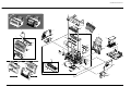
Exploded Views and Parts List
7
13
5
2
8
4
8-18
1
9
8-26
11
8-20
8-22
8-23
8-30
8-2
1-5
1-2
8-21
8-24
8-12
10
8-13
1-6
1-3
8-5
8-14
8-9
8-6
8-15
1-1
8-7
8-19
8-1
1-4
8-11
8-4
1-2
8-8
8-25
8-4-2
1-2’
8-3
8-17
8-27
8-16
8-29
8-4-1
8-28
8-10
6
1-7
ML-1210 / ML-1250
Samsung Electronics
12-1
12
ML-1220M
5-3
Exploded Views and Parts List
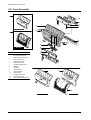
5-2 Front Assembly
0
11
SA
MS
UN
G
3
2
5
ML-1210 / ML-1250
10
0’
4
SA
MS
UN
G
10
8
ML-1220M
NO
0
6
1
12
9
DESCRIPTION
ELA HOU-COVER FRONT
7
ELA HOU-COVER FRONT
1
CBF-HARNESS-PANEL MAIN
2
PMO-COVER FRONT
3
PMO-GUIDE STACKER
4
PMO-DOOR FACE UP
5
PPR-SHEET PAPER GUIDE
6
PMO-KEY A
7
PMO-KEY B
8
PMO-LENS SED
9
PMO-COVER PCB
10
PMO-STOPPER
11
PMO-BRKT PUSH DEVE
12
PBA SUB DISP-PANEL
13
PMO-COVER FRONT, SUB IMAC
2
2’
SA
MS
UN
G
13
ML-1210 / ML-1250
5-4
ML-1220M
Samsung Electronics
Exploded Views and Parts List
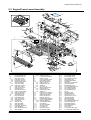
5-3 Engine/Frame Lower Assembly
2-17
2-14
2-13
2-3
3-2
3-2-2
3-2-3
3-2-1
3-2-4
1
2-3-2
2-12
2-11
2-15
2-7
3-12
3-3
3-3-1
3-2-3
3-2-1
3-4
3-6
3-5 3-6
2-16
3
2-16-2
2-16-1
2-7-3
2-7-1
2-7-2
2-9
2-9-1
2-9-2
3-10-2
2-9-3
3-45
3-25
2-9-4
2-8
3-9
3-16
3-24
3-22
3-23
3-21
2-10
3-17
3-10-1
3-10
3-41
2-3-1
3-15
3-43
3-44
3-1
2-1
2-2
2-2-1
2-2-3
2-2-2
2-6
2-5
3-8
3-7
3-26
3-11
3-22
3-23
3-21
3-28
3-19
3-13
3-14
3-32
3-38
3-27
3-39
3-30
3-29
3-18
3-26
3-31
2-4
3-34
3-42
3-33
3-20
3-35
3-36
3-40
3-37
3-46
NO
1
2
2-1
2-2
2-2-1
2-2-2
2-2-3
2-3
2-3-1
2-3-2
2-4
2-5
2-6
2-7
2-7-1
2-7-2
2-7-3
2-8
2-9
2-9-1
2-9-2
2-9-3
2-9-4
2-10
2-11
2-12
2-13
2-14
2-15
2-16
DESCRIPTION
SMPS-HVPS
ELA HOU-ENGINE ASS’Y
SOLENOID-(APOLLO)
MEC-GEAR PICKUP
PMO-GEAR_PICKUP,1
PMO-GEAR_PICKUP,2
SPRING-PICKUP,GEAR
MEC-CAM PICKUP
PMO-CAM_PICKUP
PMO-SHAFT_PICKUP
PMO-GEAR_FEED
PMO-CLUTCH_FEED
SPRING-CLUTCH
MEC-KNOCKUP ASS’Y
PMO-PLATE_KNOCKUP
PMO-CAM-KNOCKUP
IPR-BAR_KNOCKUP
SPRING-KNOCK UP
MEC-HOLDER PAD
PMO-HOLDER PAD
PMO-HOLDER_PAD
RPR-PAD FRICTION
SPRING-PAD
PMO-CAP_PAD
MEC-SIDE PAD(R)
MEC-SIDE PAD(L)
PMO-GEAR_TRANSFER
PPR-SPACER DR
MEC-TRANSFER ROLLER
MEC-TERMINAL
Samsung Electronics
NO
2-16-1
2-16-2
2-17
S-1
3
3-1
3-2
3-2-1
3-2-2
3-2-3
3-2-4
3-3
3-2-1
3-3-1
3-2-3
3-4
3-5
3-6
3-7
3-8
3-9
3-10
3-10-1
3-10-2
3-11
3-12
3-13
3-14
3-15
3-16
DESCRIPTION
TERMINAL
SPRING-HV APOLLO
PCT-INSULATOR ENG B’D
SCREW-TAPTITE
ELA HOU-FRAME LOWER
PMO-FRAME LOWER
MEA ETC-HOLDER TR L
PMO-HOLDER TR
PMO-BUSHING_TR(L)
SPRING-TR
IPR-PLATE_TR
MEA ETC-HOLDER TR R
PMO-HOLDER TR
PMO-BUSHING_TR(R)
SPRING-TR
PMO-CAP PLTE GU/DEV R
PMO-CAP PLTE GU/DEV L
SPRING-GUIDE DEVE
PMO-ACTUATOR_EXIT
PMO-HOLDER_EXIT
PMO-BUSHING_TERMINAL
ELA HOU-OPEN SENSOR
IPR-BRKT_SENSOR
CBF-HARNESS COVER
IPR-GUIDE-TR
IPR-PLATE-TERMINAL
IPR-SAW_PLATE
PCT-FILM SAW
IPR-EARTH_TRANS
IPR-GROUND_GUIDE
NO
3-17
3-18
3-19
3-20
3-21
3-22
3-23
3-24
3-25
3-26
3-27
3-28
3-29
3-30
3-31
3-32
3-33
3-34
3-35
3-36
3-37
3-38
3-39
3-40
3-41
3-42
3-43
3-44
3-45
3-46
DESCRIPTION
IPR-GROUND_HVPS
IPR-GROUND_FUSER
IPR-GROUND_DRIVE
CBF HARNESS-OPE GND
PMO-HOLDER_PR
BEARING-PRESSURE R
SPRING-PR
MEC-ROLLER_PRESSURE
PMO-GUIDE_INPUT
RMO-RUBBER_FOOT
ELA HOU-FUSER ASS’Y220V
CBF-HARNESS FUSER
ELA HOU-MOTOR GND
PMO-BUSHING SHAFT
FAN-DC
PMO-GEAR_83/35
SPRING-FUSER DR
PMO-GEAR_FU_IN 47
PMO-GEAR_FU_OUT 47
MEC-ROLLER FEED
PBA MAIN-SENSOR
EMC-HOLDER FEED
CBF HARNESS-MOTOR GND
IRP-BRKT FUSER DRV
PMO-HINGE FRONT(L)
PMO-HINGE FRONT(R)
PMO-COVER PTL
ELA HOU-PTL
PCT-COVER SHEET LAMP
PCT-INSULATOR SENSOR B’D
5-5
Exploded Views and Parts List
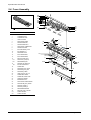
5-4 Fuser Assembly
24
30
29
27
26
28
24
23
25
17
21
0
NO
ELA HOU-FUSER ASS’Y
1
THERMISTOR-NTC
2
THERMOSTAT-150C
3
LAMP-HALOGEN
4
PMO-COVER FUSER
5
PMO-BUSHING H/R, L
6
PMO-BUSHING H/R, R
7
PMO-COVER_THERMOSTAT
8
NPR-ROLLER HEAT
9
IPR-ELECTRODE_PLATE
10
IPR-GROUND_FU
11
PMO-GUIDE CLAW
12
ELECTRODE-WIRE,1
13
ELECTRODE-WIRE,S
14
MEA ETC-SHAFT EXIT
14-1
PMO-SHAFT_EXIT(Z15)
14-2
RMO-RUBBER_EXIT
15
15-1
5-6
DESCRIPTION
0
7
S-1
13
2
9
12
20
15
15-2
15-1
4
16
1
18
S-2
14-1
14-2
22 17
PMO-ROLLER_IDLE EXIT
IPR-PIN ROLLER EXIT
16
SPRING-EXIT
17
PMO-GEAR_EXIT_DRV16
18
PMO-GEAR_EXIT_IDLE
19
PMO-GEAR_FUSER
20
LABEL (R)-CAU_HOT_FU
21
SPRING-EXIT DOWN
22
SPRING-ES, GUIDE CLAW
23
GEAR-EXIT F/DOWN
24
BEARING-EXIT FU L
25
PMO-COVER FUSER F/DOWN
26
PMO-HOLDER_EXIT_DOWN
27
PMO-EXIT_DOWN_L
28
PMO-EXIT_DOWN_S
29
RMO-RUBBER-KICKER
30
MEC-UNIT_EXIT, F_DOWN
S-1
SCREW TAPTITE
S-2
SCREW TAPTITE
10
11
14
S-1
5
3
S-1
8
19
6
Samsung Electronics
Exploded Views and Parts List
5-5 Shield Engine Unit Assembly
NO
DESCRIPTION
0
ELA HOU-SHIELD ENGINE
1
MEC-SHIELD BRKT CONTROLLER
1-1
IPR-SHIELD ENGINE
1-2
IPR-BRKT CONTROLLER
2
PCT-INSULATOR SMPS
3
CBF HARNESS-INLET ASS’Y
S-1
SCREW-MACHINE
S-2
SCREW-TAPTITE
S-3
SCREW-TAPTITE
0
2
S-1
S-2
3
S-3
1
1-1
1-2
Samsung Electronics
5-7
Exploded Views and Parts List
5-6 RX Drive Assembly
NO
DESCRIPTION
0
ELA HOU-RX DRIVE
1
MOTOR-STEP
2
PMO-GEAR_71/28
3
PMO-GEAR_73/22
4
PMO-GEAR_132/19
5
IPR-BRKT_MOTOR
6
IPR-BRKT_GEAR
7
CBF-HARNESS_MOTOR
S-7
SCREW-MACHINE
0
7
5
4
6
1
2
3
S-7
S-7
5-7 Plate-Upper Unit Assembly
NO
DESCRIPTION
0
MEC-PLATE UPPER
1
IPR-UPPER-PLATE
2
IPR-PLATE SPRING DEV
3
MEA ETC-ROLLER PICKUP
3-1
PMO-HOUSING_PICKUP
3-2
RMO-ROLLER_PICKUP
3-3
4
0
PMO-IDLE_PICKUP
MEA ETC-IDLE FEED
4-1
PMO-HOLDER_PICKUP
4-2
SPRING-FEED
4-3
6
PMO-HOLDER_IDLE,FEED
5
ICT-ROLLER_IDLE,FEED
6
CABLE CLAMP
S-1
SCREW TAPTITE
S-9
SCREW TAPTITE
4
1
3-3
4-1
4-2
3-2
3
4-3
4
3-1
4-1
3-3
2
4-2
4-3
2
5-8
5
Samsung Electronics
Block Diagram
6. Block Diagram
6-1. Block Diagram(GDI)
MAIN
USB
PC
IEEE 1284 CABLE
+5V
74LVX161284
Line
Transcei ver
Power
On
VOLTAGE Res et
DETECT OR
FLASH
MEMORY
(0 .5MB)
I N-LET
EXI T
SENSOR
POWER
CORD
MOTOR
(8MB)
Engine
SOLENOIDE
FAN
CPU
Jupiter3
DEV_FUSE
Crystal
10MHz
Mai n
Clock
LSU
FS781BZB
Video
Osci l lator Clock
44 MHz
MHV
4 LED
MHVPWM
3 KEY
SMPS
SDRAM
S3C46M0X
PANEL
B' D
+24V
POWER
SWI TCH
BIASPWM
THVPWM
OPC GND
BUFFER
HVPS
B' D
SUPPLY
DEV
TH V
Samsung Electronics
6-1
Block Diagram
6-2. Block Diagram(PCL)
MAIN
Oscillator
48 MHz
+5V
USB
PC
IEEE 1284 CABLE
USB Driver
USBN9602-28M
FLASH
MEMORY
(2MB)
VOLTAGE
DETECTOR
PANEL
B' D
Oscillator
44 MHz
Main
Clock
+24V
IN-LET
EXIT
SENSOR
POWER
CORD
MOTOR
( 4 MB)
Engine
SOLENOID
Option
Up to
68MB
FAN
DEV_FUSE
74HCT273
S3C46C0X01
74ACT273
LSU
Devided by
74HC406ON
Video
Clock
Crystal
6.7149 MHz
4 LED
MHV
OPC GND
3 KEY
MHVPWM
HVPS
BIASPWM
B' D
THVPWM
6-2
SMPS
SDRAM
Power
On
Reset
CPU
Oscillator
20 MHz
POWER
SWITCH
SUPPLY
DEV
TH V
Samsung Electronics
Connection Diagram
7. Connection Diagram
7-1. Connection Diagram(GDI)
IEEE1284
COMPATI ABLE
CABLE
HOST
COMPUTER
DCU
1
2
3
4
USB CABLE
+5V
DCU_DATA
DCU_CLK
+5V GND
SENSOR
BOARD
1
2
3
4
+5V
*PEMPTY
* FEED
+5V GND
COVER
SW ITCH
1
2
3
+24V
Not Use d
+24VS
36
PI N
J1
CN9
4PI N
CONNECTOR
f or
USB
1
2
3
4
CN13
1
2
3
4
5
6
7
8
9
CN6
1
2
+5V
PTL
1
2
CN1
1
2
3
CN7
1
THERMI STOR 2
HV PS
1
2
3
4
5
6
7
8
9
+24V_T
+24V GND
THV PW M
*THV_EA
THVRE AD
* M H VP WM
BI ASPW M
+5V
+5V GND
1
2
Main
Board
CN11
1
2
3
4
5
6
7
8
9
CN12
CN8
1
2
3
4
5
1
2
3
4
5
6
+5V
+5V GND
LED_ERROR
LED_PAPER
LED_DATA
LED_TONER
* KEY_TONER
* KEY_CANCEL
* KEY_DEMO
GDI
1
2
3
4
+24V_T
+24V GND
*PMOTOR
+3. 3V
EXT_C LK
* HSYNC
+5V
+5V GND
* LD_ON
VDO
+5V GND
1
2
3
4
5
6
7
8
9
CN3
CN5
THERM_A
THERM_B
1
2
3
4
5
6
7
8
9
10
11
1
2
3
4
5
6
7
8
9
10
11
12
13
14
15
16
17
18
19
20
21
22
23
24
+5V GND
+5V
+5V GND
+5V
+5V GND
+5V
+24V GND
+24V
+24V GND
+24V
+24V GND
+24V
EXIT
+24VS
FUSER ON
+24VS
* EGMOT_B1
CLUTCH
EGMOT_PHB
FA N
DEV_FUSE
* EGMOT _A1
* NEW_DEVE
EGMOT_PHA
1
2
3
4
5
6
7
8
9
10
11
12
13
14
15
16
17
18
19
20
21
22
23
24
POLYGON
MOTOR
LSU
LD DIODE
LED
DISPLAY
PANEL
PTL LED ARRAY
SMPS
FUSER
CN502
CN5
SOL ENOID
ENGINE
CN1
STEPPING
MOTOR
CN2
DEV_FUSE
CN3
FAN CN4
ENGI NE + SMPS
Unification B' d
Samsung Electronics
7-1
Connection Diagram
7-2. Connection Diagram(PCL)
IEEE1284
COMPATI ABLE
CABLE
HOST
COMPUTER
DCU
1
2
3
4
USB CABLE
+5V
DCU_DATA
DCU_CLK
+5V GND
SENSOR
BOARD
1
2
3
4
+5V
PEMPTY *
FEED_SENSOR*
+5V GND
COVER
SW ITCH
1
2
3
+24V
Not Use d
+24VS
36
PI N
J1
+24V_SLEEP
+24V GND
PMOTOR *
LREADY*
EXT_C LK
HSYNC *
+5V
+5V GND
LD_ON*
VDO
+5V GND
1
2
3
4
5
1
2
3
4
5
6
CN5
1
2
3
4
5
6
7
8
9
+5V
+5V GND
LED_ERROR
LED_PAPER
LED_DATA
LED_TONER
KEY_TONER*
KEY_CANCEL*
KEY_DEMO*
1
2
3
4
5
6
7
8
9
CN4
1
2
+5V
PTL
1
2
CN12
4PI N
CONNECTOR
f or
USB
1
2
3
4
1
2
3
4
1
2
3
CN7
CN9
PCL
THERMI STOR
HV PS
1
2
3
4
5
6
7
8
9
THERM_A
THERM_B
+24V_SLEEP
+24V GND
THV PW M
THV_EN*
THVRE AD
M H VP WM*
BI ASPW M
+5V
+5V GND
1
2
1
2
3
4
5
6
7
8
9
POLYGON
MOTOR
LSU
LD DIODE
LED
DISPLAY
PANEL
PTL LEDARRAY
Main
Board
CN6
CN8
CN3
1
2
1
2
3
4
5
6
7
8
9
10
11
CN11
CN2
1
2
3
4
5
6
7
8
9
10
11
12
13
14
15
16
17
18
19
20
21
22
23
24
+5V GND
+5V
+5V GND
+5V
+5V GND
+5V
+24V GND
+24V
+24V GND
+24V
+24V GND
+24V
EXIT
+24VS
FUSER ON
+24VS
MOTOR B*
CLUTCH
MOTOR_PB
FAN
DEV_FUSE
MOTOR_A*
NEW_DVE*
MOTOR_PA
1
2
3
4
5
6
7
8
9
10
11
12
13
14
15
16
17
18
19
20
21
22
23
24
SMPS
FUSER
CN502
CN5
SOL ENOID
ENGINE
CN1
STEPPING
MOTOR
CN2
DEV_FUSE
CN3
FAN CN4
ENGI NE + SMPS
Unification B' d
7-2
Samsung Electronics
Repair Manual
LASER PRINTER
ML-1200 Series
CONTENTS
1. Block Diagram
2. Connection Diagram
3. Schematic Diagrams
Samsung Electronics
3 KEY
4 L ED
P ANE L
B' D
PC
IEEE 12 84 CABLE
USB
Osci l l ator
44 MHz
VOL TAGE
DETECT OR
74LVX161284
Li ne
Transcei ver
Vi deo
Clock
Po we r
On
Re s e t
S3C46M0X
C P U
Jupiter3
MAIN
THVPWM
BI ASPW M
BUFFER
FS781BZB
MHVP WM
Mai n
Clock
Crystal
10MHz
( 8MB)
SDRAM
( 0 .5MB)
FLASH
MEMORY
B' D
HV PS
LSU
EXI T
SENSOR
+24V
+5V
Eng i ne
SMP S
TH V
DEV
SUPPL Y
OPC GND
MHV
I N- L ET
POWER
SWI TCH
DEV_FUSE
FAN
SOLENOIDE
MOTOR
POWER
CORD
1
BLOCK DIAGRAM
1. Block Diagram
1.1 GDI Block Diagram(ML-1210/ML-1220M)
Repair Manual
1-1
1-2
3 KEY
4 L ED
P ANE L
B' D
PC
IEEE 12 84 CABLE
USB
Oscillator
44 MHz
Oscillator
20 MHz
VOLTAGE
DETECTOR
Video
Clock
Main
Clock
Power
On
Reset
USB Driver
USBN9602-28M
Oscillator
48 MHz
S3C46C0X01
CPU
MAIN
B' D
BI ASPW M
THVPWM
HV PS
LSU
EXIT
SENSOR
+24V
MHVP WM
Crystal
6.7149 MHz
Devided by
74HC406ON
74ACT273
74HCT273
Option
Up to
68MB
( 4 MB)
SDRAM
(2MB)
FLASH
MEMORY
+5V
Eng i ne
SMPS
TH V
DEV
SUPPL Y
OPC GND
MHV
IN-LET
POWER
SWITCH
DEV_FUSE
FAN
SOLENOI D
MOTOR
POWER
CORD
BLOCK DIAGRAM
1.2 PCL Block Diagram(ML-1250)
Repair Manual
Samsung Electronics
2
CONNECTION DIAGRAM
2. Connection Diagram
2.1 GDI Connection Diagram(ML-1210/ML-1220M)
IEEE1284
COMPATI ABLE
CABLE
HOST
COMPUTER
DCU
1
2
3
4
USB CABLE
+5V
DCU_DATA
DCU_CLK
+5V GND
36
PI N
J1
CN9
SENSOR
BOARD
1
2
3
4
COVER
SWITCH
1
2
3
+24V
Not Use d
+24VS
CONNECTOR
f or
USB
1
2
3
4
CN3
CN13
1
THERMI STOR 2
HV PS
1
2
3
4
5
6
7
8
9
+24V_T
+24V GND
THV PWM
*THV_EA
THVRE AD
* M H VP WM
BI ASPW M
+5V
+5V GND
1
2
3
4
5
1
2
3
4
5
6
1
2
3
4
1
2
3
1
2
1
2
3
4
5
6
7
8
9
1
2
3
4
5
6
7
8
9
+5V
+5V GND
LED_ERROR
LED_PAPER
LED_DATA
LED_TONER
* KEY_TONER
* KEY_CANCEL
* KEY_DEMO
1
2
3
4
5
6
7
8
9
1
+5V
PTL
1
2
CN1
CN7
CN6 2
Main
Board
CN11
CN5
THERM_A
THERM_B
+24V_T
+24V GND
*PMOTOR
+3. 3V
EXT_C LK
* HSYNC
+5V
+5V GND
* LD_ON
VDO
+5V GND
POLYGON
MOTOR
LSU
LD DIODE
4PI N
GDI
+5V
*PEMPTY
* FEED
+5V GND
1
2
3
4
5
6
7
8
9
10
11
CN12
CN8
1
2
3
4
5
6
7
8
9
10
11
12
13
14
15
16
17
18
19
20
21
22
23
24
+5V GND
+5V
+5V GND
+5V
+5V GND
+5V
+24V GND
+24V
+24V GND
+24V
+24V GND
+24V
EXIT
+24VS
FUSER ON
+24VS
* EGMOT_B1
CLUTCH
EGMOT_PHB
FA N
DEV_FUSE
* EGMOT _A1
* NEW_DEVE
EGMOT_PHA
1
2
3
4
5
6
7
8
9
10
11
12
13
14
15
16
17
18
19
20
21
22
23
24
LED
DISPLAY
PANEL
PTL LEDARRAY
SMPS
FUSER
CN502
CN5
SOL ENOID
ENGINE
CN1
STEPPING
MOTOR
CN2
DEV_FUSE
CN3
FAN CN4
ENGI NE + SMPS
Unification B' d
Repair Manual
Samsung Electronics
2-1
CONNECTION DIAGRAM
2-2 PCL Connection Diagram(ML-1250)
IEEE1284
COMPATI ABLE
CABLE
HOST
COMPUTER
USB CABLE
36
PI N
CONNECTOR
f or
USB
1
2
3
4
SENSOR
BOARD
1
2
3
4
+5V
PEMPTY *
FEED_SENSOR*
+5V GND
1
2
3
4
COVER
SW ITCH
1
2
3
+24V
Not Use d
+24VS
1
2
3
1
2
3
4
1
2
3
4
5
1
2
3
4
5
6
CN5
1
2
3
4
5
6
7
8
9
+5V
+5V GND
LED_ERROR
LED_PAPER
LED_DATA
LED_TONER
KEY_TONER*
KEY_CANCEL*
KEY_DEMO*
1
2
3
4
5
6
7
8
9
CN4
1
2
+5V
PTL
1
2
CN12
CN7
CN9
PCL
1
THERMI STOR 2
HV PS
1
2
3
4
5
6
7
8
9
+24V_SLEEP
+24V GND
THV PWM
THV_EN*
THVRE AD
M H VP WM*
BI ASPW M
+5V
+5V GND
LSU
LD DIODE
1
2
1
2
3
4
5
6
7
8
9
LED
DISPLAY
PANEL
PTL LEDARRAY
Main
Board
CN6
CN8
CN3
THERM_A
THERM_B
POLYGON
MOTOR
4PI N
+5V
DCU_DATA
DCU_CLK
+5V GND
DCU
J1
+24V_SLEEP
+24V GND
PMOTOR *
LREADY*
EXT_C LK
HSYNC *
+5V
+5V GND
LD_ON*
VDO
+5V GND
1
2
3
4
5
6
7
8
9
10
11
CN11
CN2
1
2
3
4
5
6
7
8
9
10
11
12
13
14
15
16
17
18
19
20
21
22
23
24
+5V GND
+5V
+5V GND
+5V
+5V GND
+5V
+24V GND
+24V
+24V GND
+24V
+24V GND
+24V
EXIT
+24VS
FUSER ON
+24VS
MOTOR B*
CLUTCH
MOTOR_PB
FAN
DEV_FUSE
MOTOR_A*
NEW_DVE*
MOTOR_PA
1
2
3
4
5
6
7
8
9
10
11
12
13
14
15
16
17
18
19
20
21
22
23
24
SMPS
FUSER
CN502
CN5
SOL ENOID
ENGINE
CN1
STEPPING
MOTOR
CN2
DEV_FUSE
CN3
FAN CN4
ENGI NE + SMPS
Unification B' d
2-2
Repair Manual
Samsung Electronics
3
SCHEMATIC DIAGRAMS
3. Schematic Diagrams
3.1 GDI Main Circuit Diagram (1/5)
Repair Manual
Samsung Electronics
3-1
SCHEMATIC DIAGRAMS
Main Circuit Diagram (2/5)
3-2
Repair Manual
Samsung Electronics
SCHEMATIC DIAGRAMS
Main Circuit Diagram (3/5)
Repair Manual
Samsung Electronics
3-3
SCHEMATIC DIAGRAMS
Main Circuit Diagram (4/5)
3-4
Repair Manual
Samsung Electronics
SCHEMATIC DIAGRAMS
Main Circuit Diagram (5/5)
Repair Manual
Samsung Electronics
3-5
SCHEMATIC DIAGRAMS
3.2 PC L Main Circuit Diagram (1/9)
3-6
Repair Manual
Samsung Electronics
SCHEMATIC DIAGRAMS
PCL Main Circuit Diagram (2/9)
Repair Manual
Samsung Electronics
3-7
SCHEMATIC DIAGRAMS
PCL Main Circuit Diagram (3/9)
3-8
Repair Manual
Samsung Electronics
SCHEMATIC DIAGRAMS
PCL Main Circuit Diagram (4/9)
Repair Manual
Samsung Electronics
3-9
SCHEMATIC DIAGRAMS
PCL MainCircuit Diagram (5/9)
3-10
Repair Manual
Samsung Electronics
SCHEMATIC DIAGRAMS
PCL Main Circuit Diagram (6/9)
Repair Manual
Samsung Electronics
3-11
SCHEMATIC DIAGRAMS
PCL Main Circuit Diagram (7/9)
3-12
Repair Manual
Samsung Electronics
SCHEMATIC DIAGRAMS
PCL Ma in Circuit Diagram (8/9)
Repair Manual
Samsung Electronics
3-13
SCHEMATIC DIAGRAMS
PCL Main Circuit Diagram (9/9)
3-14
Repair Manual
Samsung Electronics
SCHEMATIC DIAGRAMS
3.3 HVPS Circuit Diagram (1/2)
5V
18V
C402
103
R401
100
R403
110KF
Q401
A708-Y
MHV-PWM
3
CN1-#6
T401
KAB-006
R405
220KF
R411
2.2K
R422
5.6K
24VS
R407
240K
R404
33K
12
+
13
4
Q402
D526-Y
14
R426
MGR1/2W 100KF
MHV
R413
MGR1/2W 6MF
6
C405
2KV 680
R408
47K
U1-D
KA324
D401
4KV
C404
3KV 471
7
5
2
-
D111
1N4148
R402
56KF
U2-B
7407
1
C406
3KV 471
D402
4KV
R414
MGR1/2W 6MF
4
R412
2K
C408
104
C401
222
R409
430
R406
2.2KF
C403
333
VR401
50K
OPC
R410
1W 3
ZD401
1W 130V
D403
1N4148
24VS
5V
T501
KAB-006
18V
R501
5.6K
R503
100
R510
47K
C503
104
R508
86.6KF
Q502
D526-Y
1
CN1-#7
2
U2-A
7407
R507
27K
R502
2.2K
R505
100KF
R506
100KF
+
8
7
5
2
6
C502
222
VR501
50K
R509
12KF
R514
MGR1/2W 15MF
R417
MGR1/2W 15MF
R516
MGR1/2W 50K
SUPPLY
C505
2KV 680
C506
3KV 471
ZD501
1W 100V
4
R511
47K
U1-C
KA324
C501
104
R504
2K
9
10
D502
4KV
1
Q501
A708-Y
BIAS-PWM
R416
MGR1/2W 15MF
C504
333
D501
1N4148
R515
MGR1/2W 15MF
R512
430
DEV
R519
MGR1/2W 50K
R517
MGR1/2W 15MF
R513
1W 3
CN1
GIL-S-9P-S2T2-EF
1
2
3
4
5
6
7
8
9
24VS
A-GND
THV-PWM
THV-EA
THV-READ
MHV-PWM
BIAS-PWM
5V
D-GND
24VS
U3
KA7818
IN
OUT
18V
+
GND
C1
104
C2
104
SAMSUNG ELECTRONICS
TITLE
SWALLOW-HVPS
DESIGNED CHECKED APPROVED DRW. NO
C3
35V 47uF
REF. NO
JC
SIZE A4
DATE 01/01/04
REV.
1.0
JH.CHO
1 OF 2
Repair Manual
Samsung Electronics
3-15
SCHEMATIC DIAGRAMS
HVPS Circuit Diagram (2/2)
T201
HVT-2A
24VS
5V
18V
1
C208
6KV 471
C206
6KV 471
7
D204
6KV
R201
10K
THV-PWM
R206
100
13
CN1-#3
12
11
10
U2-F
7407
R205
1K
U2-E
7407
24VS
+
Q204
D526-Y
D201
1N4148
R208
30KF
Q203
A708-Y
5
C201
103
R209
110KF
R207
2K
U1-B
KA324
C101
35V 47uF
VR201
50K
C202
331
6
R210
510KF
R213
2.2K
7
C209
6KV 471
C207
6KV 471
THV
R212
470K
C203
D203
472 1N4148
ZD201
5.6V
R215
430
R216
BR1/2W 30MJ
R218
MGR1/2W 100KF
C204
473
ZD202
7.5V
R217
BR1/2W 200MG
18V
R3
1/2W 560
ZD1
5.6V
18V
C7
104
R309
2.2K
14
CN1-#4
C205
6KV 101
D207
6KV
4
R211
1MF
THV-EA
6
-
R214
1.2K
D202
1N4148
5V
CN1-#8
+
5
2
D206
6KV
D205
6KV
9
T301
KAB-006
Q301
A708-Y
C307
3KV 471
1
7
5
2
6
D304
4KV
8
R315
BR1/2W 30MJ
R307
33K
7
U2-C
7407
C306
2KV 680
Q303
D526-Y
18V
D-GND
24VS
D303
4KV
C308
3KV 471
4
D301
1N4148
C4
104
R308
33K
R310
2.2K
4
THV-READ
+
1
R316
1KF
CN1-#5
-
U1-A
KA324
Q302
A708-Y
3
2
R302
33K
R303
100KF
R306
26.1KF
R304
200KF
R314
2.2KF
R311
100KF
VR302
5K
C305
333
11
C303
333
R317
2KF
R305
5.1KF
R301
470K
C302
102
D302
1N4148
VR301
10K
C301
222
C304
500V 103
SAMSUNG ELECTRONICS
TITLE
SWALLOW-HVPS
DESIGNED CHECKED APPROVED DRW. NO
REF. NO
REV.
JC
1.0
JH.CHO
SIZE A4
3-16
DATE 01/01/04
2 OF 2
Repair Manual
Samsung Electronics
SCHEMATIC DIAGRAMS
3.4 SMPS Circuit Diagram (110V)
R502
F501
1/2W
560K
125V 8A
F502
LF501
125V 3A
APOLLO12
LF502
APOLLO12
V501
SCK-054
T501
R518
C522
EER2828
22
1KV 102
CN501
R509
1W
82
3W
47K
104
C520
300uH
C504
U502
104
R513
+24VS
FB
GND
R512
330
6
10
NB
N5
2.2K-F
50V 33uF
PC501
R511
C513
1uF
C515
7 1000uF
R504
C518
K1010H
4.3K
10V
5
CN5-1,3,5
R515
U503
68K
KA431
1
R521
R520
150
47K
+5V 1.0A
C517
104
EXIT
CN5-14
R516
OP501
2.2K-F
ITR8406-S
PC501
1/2W
1.5K
+5V
2A 223K
R510
L502
D503
C510
1W
0.3
1KV 102
SB1040FCT
C509
KMOC3063
104
10uH
APOLLO12
1W 180
FUSIBLE
PC502
C514
22
3
1/4W
100
R508
R514
30
4
C507
C519
5W
500
GND
R507
ER102
5
VCC
3
BTA12-600
R503
DRAIN
OCP
U501
2
2
1
D501
B501
STRT-G6153
1
R519
CN5-8,10,12
2
333
11
3
D502
C521
UF1010
2KV 221K
R506
CN502
N24
NP
1W
47K
L501
1W 47
FUSIBLE
CN5-7,9,11
+24V 1.8A
12
1
C512
R501
D504
ER1002FCT
C511
C505
222MAD
R517
10V 470uF
FL406
C502
TNR502 C503
1W
47K
103
BD501
TNR501
R505
50V 1000uF
+
224
-
50V 1000uF
C508
222MAD
200V 470uF
N
C501
TVR 10D 561K
TVR 14D 221K
L
F.G
CN5-2,4,6
K1010H
C506
GND
222MAD
CN5-13,15
+24VS2
NO MARKING RESISTOR 1/4W-J (5%)
50V 47uF
GND
C1
U1
A2918SWH
VBB
VCC
5
2B
331
CN2
1
17
1
2
2
4
3
4
C2
RC2
E1
12 16 5
E2
2A
SENSE2
1B
VREF
1A
+ENABLE1
+ENABLE2
GND
PHASE1
PHASE2
RC1
14
7
SENSE1
13
8
+EGMOT_A1
+EGMOT_B1
+24VS
+24V
CN4
GND
11
EGMOT_PHA
EGMOT_PHB
CN5-16
C3
15 18 3 6 9
35303-0450
+5V
331
FAN
35301-0350
Q3
R13
2.2K
D3
3
2
1
1N4003
C8
1N4003
50V 47uF
FUSER_ON
1008-Y
R2
CLUTCH
R12
510
D2
CN1
2
1
35303-0250
Q1
1008-Y
R1
5.6K
5.6K
GND
GND
R7
GND
56K
1K
C7
103
R6
GND
2W 0.37
331
R11
2W 0.37
R10
C5
1.2K
R8
1K
C6
R5
103
R15
56K
C4
331
GND
R9
17.4K-F
GND
Repair Manual
Samsung Electronics
3-17
SCHEMATIC DIAGRAMS
SMPS Circuit Diagram (220V)
R502
F501
1/2W
560K
250V 5A
F502
LF501
250V 2A
APOLLO12
V501
LF502
T501
SCK-054
APOLLO12
R518
C522
22
1KV 102
EER2828
CN501
R509
1W
82
3W
47K
CN5-7,9,11
C520
1W
100K
300uH
C504
333
U502
1/4W
22
R513
FB
330
4
50V 33uF
5
R504
7
PC501
K1010H
4.3K
N5
CN5-1,3,5
R515
2.2K-F
R511
10
NB
C518
C513
1uF
C515
10V
1000uF
22K
U503
KA431
1
R521
R520
150
47K
+5V 1.0A
C517
104
EXIT
CN5-14
R516
OP501
2.2K-F
ITR8406-S
CN5-2,4,6
K1010H
C506
GND
332MAD
CN5-13,15
+24VS
R512
PC501
1/2W
1.5K
+5V
2A 223K
1W
0.6
L502
D503
C510
R510
1KV 102
SB1040FCT
C509
KMOC3063
C514
22
10uH
6
PC502
R514
30
1W 180
FUSIBLE
104
104
GND
APOLLO12
3
R508
C507
C519
5W
500
CN5-8,10,12
R507
ER102
5
VCC
OCP
BTA12-600
R503
DRAIN
GND
1
U501
2
2
1
D501
B501
STRT-G6153
R519
3
1W 47
FUSIBLE
CN502
11
3
D502
C521
UF1010
1KV 221K
R506
L501
N24
NP
10V 470uF
104
+24V 1.8A
12
1
C512
R501
D504
ER1002FCT
C511
C505
222MAD
R517
2
FL406
C502
C503
1W
100K
103
BD501
TNR501
R505
50V 1000uF
+
224
-
450V 150uF
N
C508
222MAD
50V 1000uF
C501
TVR 10D 561K
L
F.G
+24VS2
NO MARKING RESISTOR 1/4W-J (5%)
50V 47uF
5
331
1A
PHASE1
PHASE2
1B
CN2
1
17
1
2
2
4
3
4
C2
RC2
E1
12 16 5
SENSE2
2B
E2
+ENABLE2
GND
2A
VREF
+ENABLE1
RC1
+EGMOT_A1
+EGMOT_B1
14
7
SENSE1
13
8
C1
U1
A2918SWH
VBB
VCC
11
+24V
+24VS
CN4
GND
GND
EGMOT_PHA
EGMOT_PHB
CN5-16
C3
35303-0450
+5V
331
15 18 3 6 9
FAN
3
2
1
35301-0350
Q3
R13
2.2K
D3
1N4003
C8
1N4003
50V 47uF
FUSER_ON
1008-Y
R2
CLUTCH
2
1
35303-0250
Q1
R12
510
CN1
D2
1008-Y
R1
5.6K
5.6K
GND
R7
GND
3-18
56K
1K
C7
103
R8
R6
GND
1K
2W 0.37
331
R11
2W 0.37
R10
C5
1.2K
R5
C6
103
R15
56K
C4
331
R9
17.4K
GND GND
Repair Manual
Samsung Electronics
SCHEMATIC DIAGRAMS
3.5 Panel Circuit Diagram
Repair Manual
Samsung Electronics
3-19
This manual is made and
described centering around
circuit diagram
and circuit description needed
in the repair center
in the form of appendix.
Samsung Electronics Digital Printing
CS Group
Copyright (c) 2001. 10
Contents
CONTENTS
1. Precautions . . . . . . . . . . . . . . . . . . . . . . . . . . . . . . . . . . . . . . . . . .page(1-1)
1-1 Safety Precautions . . . . . . . . . . . . . . . . . . . . . . . . . . . . . . . . . . . . .page(1-1)
1-2 Precautions on Disassembly and Reassembly . . . . . . . . . . . . . . .page(1-1)
1-3 Tools for Troubleshooting . . . . . . . . . . . . . . . . . . . . . . . . . . . . . . . .page(1-2)
2. Specifications . . . . . . . . . . . . . . . . . . . . . . . . . . . . . . . . . . . . . . . . .page(2-1)
3. Disassembly and Reassembly . . . . . . . . . . . . . . . . . . . . . . . . . . .page(3-1)
3-1 Cover Assembly . . . . . . . . . . . . . . . . . . . . . . . . . . . . . . . . . . . . . . .page(3-1)
3-2 LED Panel PBA . . . . . . . . . . . . . . . . . . . . . . . . . . . . . . . . . . . . . . .page(3-2)
3-3 LSU(Laser Scanning Unit) . . . . . . . . . . . . . . . . . . . . . . . . . . . . . . .page(3-2)
3-4 Transfer Roller . . . . . . . . . . . . . . . . . . . . . . . . . . . . . . . . . . . . . . . .page(3-3)
3-5 Motor Assembly . . . . . . . . . . . . . . . . . . . . . . . . . . . . . . . . . . . . . . .page(3-3)
3-6 HVPS Board . . . . . . . . . . . . . . . . . . . . . . . . . . . . . . . . . . . . . . . . . .page(3-4)
3-7 Fuser Assembly . . . . . . . . . . . . . . . . . . . . . . . . . . . . . . . . . . . . . . .page(3-4)
3-8 Thermostat and Halogen Lamp . . . . . . . . . . . . . . . . . . . . . . . . . . .page(3-5)
3-9 SMPS Board . . . . . . . . . . . . . . . . . . . . . . . . . . . . . . . . . . . . . . . . .page(3-6)
3-10 Main Board and Sensor Board . . . . . . . . . . . . . . . . . . . . . . . . . . .page(3-7)
4. Troubleshooting . . . . . . . . . . . . . . . . . . . . . . . . . . . . . . . . . . . . . . .page(4-1)
4-1 How to use DCU . . . . . . . . . . . . . . . . . . . . . . . . . . . . . . . . . . . . . .page(4-2)
4-2 The cause and solution of Bad image . . . . . . . . . . . . . . . . . . . . . .page(4-5)
4-3 The cause and solution of the bad discharge. . . . . . . . . . . . . . . . .page(4-12)
4-4 The cause and solution of the malfunction . . . . . . . . . . . . . . . . . . .page(4-16)
4-5 Toner Cartridge Service . . . . . . . . . . . . . . . . . . . . . . . . . . . . . . . . .page(4-21)
4-6 The cause and solutions of bad environment of the software . . . .page(4-25)
5. Exploded Views and Parts List . . . . . . . . . . . . . . . . . . . . . . . . . . .page(5-1)
5-1 Expolded Views and Parts List . . . . . . . . . . . . . . . . . . . . . . . . . . . .page(5-2)
5-2 Front Assembly . . . . . . . . . . . . . . . . . . . . . . . . . . . . . . . . . . . . . . .page(5-4)
5-3 Engine/Frame Lower Assembly . . . . . . . . . . . . . . . . . . . . . . . . . . .page(5-6)
5-4 Fuser Assembly . . . . . . . . . . . . . . . . . . . . . . . . . . . . . . . . . . . . . . .page(5-8)
5-5 Shield Engine Unit Assembly . . . . . . . . . . . . . . . . . . . . . . . . . . . . .page(5-10)
5-6 RX Drive Assembly . . . . . . . . . . . . . . . . . . . . . . . . . . . . . . . . . . . .page(5-12)
5-7 Plate-Upper Unit Assembly . . . . . . . . . . . . . . . . . . . . . . . . . . . . . .page(5-14)
6. Block Diagram . . . . . . . . . . . . . . . . . . . . . . . . . . . . . . . . . . . . . . . .page(6-1)
6-1 Block Diagram(GDI) . . . . . . . . . . . . . . . . . . . . . . . . . . . . . . . . . . . .page(6-1)
6-2 Block Diagram(PCL) . . . . . . . . . . . . . . . . . . . . . . . . . . . . . . . . . . .page(6-2)
7. Connection Diagram . . . . . . . . . . . . . . . . . . . . . . . . . . . . . . . . . . .page(7-1)
7-1 Connection Diagram(GDI) . . . . . . . . . . . . . . . . . . . . . . . . . . . . . . .page(7-1)
7-2 Connection Diagram(PCL) . . . . . . . . . . . . . . . . . . . . . . . . . . . . . . .page(7-2)
Samsung Electronics