1
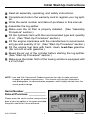
e
p on
e t-u ge
Se tar pa
l s on
tia s
ini tion
uc
tr
ins
Iron & Oak
20, 22, and 26 Ton
Vertical / Horizontal Log Splitters
Standard & DURO-GLIDE Models
Models: BHVH2209
BHVH2209FC
BHVH2609
Owner / Operator
and Safety Manual
Initial Start-Up Instructions
❏ Read all assembly, operating, and safety instructions.
❏ Complete and return the warranty card to register your log splitter.
❏ Write the serial number and date-of-purchase in this manual.
❏ Assemble the log splitter.
❏ Make sure the oil filter is properly installed. (See “Assembly
Procedure” section.)
❏ Fill the hydraulic tank with the recommended type and quantity
of oil. (See “Start-Up Procedure” section.)
❏ Fill the engine crankcase with the manufacturer’s recommended type and quantity of oil. (See “Start-Up Procedure” section.)
❏ Fill the engine fuel tank with fresh, clean, lead-free gasoline.
(Do not mix oil with gasoline.)
❏ Bleed the air out of the cylinder before starting the log splitter.
(See “Start-Up Procedure” section.)
❏ Make sure the trailer hitch of the towing vehicle is equipped with
a 2 inch ball.
NOTE: Iron and Oak Commercial Products reserves the right to make technical
changes for product improvement. This manual may contain illustrations
and photographs, for demonstration purposes, which slightly deviate from the
actual product design.
Serial Number ______________
Date-of-Purchase ___________
Please enter the serial number and purchase
date of your log splitter in the space provided.
Keep this manual for future reference.
815-672-8596
1
Iron & Oak
Contents
Introduction . . . . . . . . . . . . . . . . . . . . . . . . . . . . . . . . . . . . . . . . . . . . . . . . . . . . . . . . 4
Safety . . . . . . . . . . . . . . . . . . . . . . . . . . . . . . . . . . . . . . . . . . . . . . . . . . . . . . . . . . . . . 5
Personal Protection . . . . . . . . . . . . . . . . . . . . . . . . . . . . . . . . . . . . . . . . . . . . . . . . . 5
Worksite Safety . . . . . . . . . . . . . . . . . . . . . . . . . . . . . . . . . . . . . . . . . . . . . . . . . . . . 5
Operating Safety . . . . . . . . . . . . . . . . . . . . . . . . . . . . . . . . . . . . . . . . . . . . . . . . . . . 6
Log Splitting Safety . . . . . . . . . . . . . . . . . . . . . . . . . . . . . . . . . . . . . . . . . . . . . . . . . 7
Maintenance and Repair . . . . . . . . . . . . . . . . . . . . . . . . . . . . . . . . . . . . . . . . . . . . . 7
Towing . . . . . . . . . . . . . . . . . . . . . . . . . . . . . . . . . . . . . . . . . . . . . . . . . . . . . . . . . . . 8
Refueling . . . . . . . . . . . . . . . . . . . . . . . . . . . . . . . . . . . . . . . . . . . . . . . . . . . . . . . . . 8
Preventing Fires . . . . . . . . . . . . . . . . . . . . . . . . . . . . . . . . . . . . . . . . . . . . . . . . . . . . 9
Assembly Instructions. . . . . . . . . . . . . . . . . . . . . . . . . . . . . . . . . . . . . . . . . . . . . . . 10
Required Tools . . . . . . . . . . . . . . . . . . . . . . . . . . . . . . . . . . . . . . . . . . . . . . . . . . . . 10
Shipping List. . . . . . . . . . . . . . . . . . . . . . . . . . . . . . . . . . . . . . . . . . . . . . . . . . . . . . 10
Unpacking the Crate. . . . . . . . . . . . . . . . . . . . . . . . . . . . . . . . . . . . . . . . . . . . . . . . 11
Assembly Procedure . . . . . . . . . . . . . . . . . . . . . . . . . . . . . . . . . . . . . . . . . . . . . . . 12
Start-Up Procedure . . . . . . . . . . . . . . . . . . . . . . . . . . . . . . . . . . . . . . . . . . . . . . . . . 17
Towing . . . . . . . . . . . . . . . . . . . . . . . . . . . . . . . . . . . . . . . . . . . . . . . . . . . . . . . . . . . . 19
Operation . . . . . . . . . . . . . . . . . . . . . . . . . . . . . . . . . . . . . . . . . . . . . . . . . . . . . . . . . 21
Operation - Horizontal Position . . . . . . . . . . . . . . . . . . . . . . . . . . . . . . . . . . . . . . . 22
Operation - Vertical Position . . . . . . . . . . . . . . . . . . . . . . . . . . . . . . . . . . . . . . . . . 25
Inspection and Maintenance . . . . . . . . . . . . . . . . . . . . . . . . . . . . . . . . . . . . . . . . . . 28
General Maintenance Check (before operating) . . . . . . . . . . . . . . . . . . . . . . . . . . 28
Engine Service . . . . . . . . . . . . . . . . . . . . . . . . . . . . . . . . . . . . . . . . . . . . . . . . . . . . 28
Storage. . . . . . . . . . . . . . . . . . . . . . . . . . . . . . . . . . . . . . . . . . . . . . . . . . . . . . . . . . 28
Hydraulic Oil Change . . . . . . . . . . . . . . . . . . . . . . . . . . . . . . . . . . . . . . . . . . . . . . . 29
Specifications . . . . . . . . . . . . . . . . . . . . . . . . . . . . . . . . . . . . . . . . . . . . . . . . . . . . . . 31
Mechanical Specifications . . . . . . . . . . . . . . . . . . . . . . . . . . . . . . . . . . . . . . . . . . . 31
Hydraulic Specifications . . . . . . . . . . . . . . . . . . . . . . . . . . . . . . . . . . . . . . . . . . . . 32
Replacement Filters . . . . . . . . . . . . . . . . . . . . . . . . . . . . . . . . . . . . . . . . . . . . . . . . 32
Hydraulic Oil Specifications (non foaming) . . . . . . . . . . . . . . . . . . . . . . . . . . . . . . 32
Troubleshooting . . . . . . . . . . . . . . . . . . . . . . . . . . . . . . . . . . . . . . . . . . . . . . . . . . . . 33
Decals . . . . . . . . . . . . . . . . . . . . . . . . . . . . . . . . . . . . . . . . . . . . . . . . . . . . . . . . . . . . 34
Parts . . . . . . . . . . . . . . . . . . . . . . . . . . . . . . . . . . . . . . . . . . . . . . . . . . . . . . . . . . . . . 36
Warranty . . . . . . . . . . . . . . . . . . . . . . . . . . . . . . . . . . . . . . . . . . . . . . . . . . . . . . . . . . 44
Warranty Card. . . . . . . . . . . . . . . . . . . . . . . . . . . . . . . . . . . . . . . . . . . . . . . . . . . . . . 45
Optional Attachments . . . . . . . . . . . . . . . . . . . . . . . . . . . . . . . . . . . . . . . . . . . . . . . 47
Log Cradle . . . . . . . . . . . . . . . . . . . . . . . . . . . . . . . . . . . . . . . . . . . . . . . . . . . . . . . 47
Log Dislodger . . . . . . . . . . . . . . . . . . . . . . . . . . . . . . . . . . . . . . . . . . . . . . . . . . . . . 47
Safety Flag Kit . . . . . . . . . . . . . . . . . . . . . . . . . . . . . . . . . . . . . . . . . . . . . . . . . . . . 48
Iron & Oak
2
815-672-8596
WARNING
To avoid personal injury or death, carefully read and understand all
instructions pertaining to the Iron & Oak Commercial Products’ log
splitter.
Do not attempt to assemble, operate, or maintain our product without
fully understanding all our instructions and safety precautions. Do
not operate the log splitter unless you read and understand the
instructions and warnings in this manual. If any doubt or question
arises about the correct or safe method of performing anything found
in this or other Iron & Oak Commercial Products’ manuals, contact
your Iron & Oak Commercial Products’ dealer or call the Sales and
Service representatives at our main headquarters. Proper care is
your responsibility.
WARNING
Accidents can often be avoided by being alert and recognizing potentially hazardous situations. Any individuals operating, maintaining, or repairing products manufactured by Iron & Oak Commercial Products should have the necessary training, skills, and tools required to perform these functions properly
and safely. The safety information in this manual serves as a basic guide in an
attempt to prevent injury or death.
Iron & Oak Commercial Products cannot anticipate every possible circumstance that might involve a potential hazard. The warnings in this manual and
on the product itself are, therefore, not all inclusive. If tools, procedures, work
methods, or operating techniques that are not specifically mentioned by Iron &
Oak Commercial Products are used, you must satisfy yourself that they are safe
for you and for others. Make sure the log splitter will not be damaged or made
unsafe by any operation, lubrication, maintenance, or repair procedures that
you choose.
DO NOT proceed if any doubt arises about the correct or safe method of performing anything found in this or other Iron & Oak Commercial Products’ manuals. Seek out expert assistance from a qualified person before continuing.
WARNING
CALIFORNIA PROPOSITION 65
Engine exhaust from this product contains chemicals known to the State of California to cause cancer, birth defects, or other reproductive harm.
815-672-8596
3
Iron & Oak
Introduction
The commercial BHVH2209, BHVH2209FC, and BHVH2609 Vertical/Horizontal Log
Splitters are designed for tough applications in both vertical and horizontal positions.
With 22 tons (model BHVH2209) or 26 tons (model BHVH2609) of splitting force, a 12
second cycle time, and a 6 HP or an 9 HP engine either model will handle most of your
commercial log splitting needs. The BHVH2209FC features an 8 second cycle time, 20
tons of splitting force, and an 9 HP engine.
The DURO-GLIDE rail/wedge system, if equipped, provides the longest possible wear
life of the sliding wedge. Composite material wear pads built into the wedge provide
more efficient splitting, more splitting power, and eliminates metal-to-metal contact.
An attractive, powder-coated finish provides the finest protection available, and Iron &
Oak’s rigid, quality-control and component testing help ensure years of productive, reliable service. Since 1982, the name Iron & Oak has stood for quality and reliability when
it comes to log splitters and wood processing products.
Iron & Oak Commercial Products offers the finest commercial log splitter on the market
today!
✔ Rugged, heavy-duty construction for years of exceptional service.
✔ Ergonomic design for use in vertical and horizontal operating positions.
✔ Rigid, quality-control during manufacturing ensures greater reliability.
✔ Factory testing of all major components and hydraulic tank.
✔ Powder-coated finish for the best appearance and weather protection.
✔ Year-round manufacturing, parts, and support.
For additional information, contact us at:
Iron & Oak Commercial Products
410 W. Broadway Ave.
P.O. Box 577
Streator, Illinois 61364-0577
Phone: (815) 672-8596
Fax: (815) 672-9073
E-mail: [email protected]
Web Site: www.logsplitters-ironoak.com
Iron & Oak
4
815-672-8596
Safety
The following is a list of safety rules you must follow in order to use your log splitter safely.
Personal Protection
✔
To avoid personal injury or death, carefully read and understand all instructions pertaining to the log splitter including the engine manufacturer’s operating and maintenance instruction manual.
✔
Always wear protective gear, such as safety
goggles, tight-fitting gloves without draw
strings or loose cuffs, steel-toed shoes, and a
protective hearing device.
✔
AR N I
To prevent injury, make sure all decals are attached to the log splitter and
are legible at all times.
NG
Worksite Safety
✔
To avoid tripping, do not leave tools, logs, or other components laying around
the work area.
✘
NEVER operate your log splitter on slippery, wet, muddy, or icy surfaces. The
location you choose should be flat, dry, and free from any tall grass, brush,
or other interferences.
✘
NEVER operate the engine in an enclosed area. Exhaust fumes contain carbon monoxide that can be deadly when inhaled. Make sure the area is well
ventilated.
✘
NEVER attempt to move your log splitter over hilly or uneven terrain without a
tow vehicle.
✘
NEVER use your log splitter at night.
✔
ALWAYS operate your log splitter on dry, solid, level ground.
✔
ALWAYS block the wheels to prevent movement of the machine while in
operation.
815-672-8596
5
Iron & Oak
Safety
Operating Safety
✔
ALLOW ONLY ONE (1) PERSON TO LOAD AND OPERATE THE LOG SPLITTER.
✔
Allow only adults to operate the log splitter. No one under the age of 18 should
be allowed to operate the log splitter.
✔
Always keep bystanders, including children and pets, at least twenty-five (25)
feet away from the work area. Only the operator should stand near the equipment and only within the safe operating area prescribed in this manual (see the
photos on safe and unsafe operating zones in the “Operation” section.)
✔
When the ram of the log splitter is in the return mode, keep your hands off the
machine — the log splitter is designed to automatically stop when the cylinder
is fully retracted.
✔
ALWAYS disconnect the spark plug wire when the log splitter is not in operation.
✘
Do not allow any person to operate the log splitter until they have read and
understood the safe operating instructions contained in this manual.
✘
Do not, under any circumstances, alter your log splitter. This equipment was
designed and engineered to be used in accordance with the operating instructions. Altering the equipment, or using the equipment in such a way as to circumvent its design capabilities and capacities, could result in serious or fatal
injury and WlLL VOID THE WARRANTY.
✘
Never operate, or allow anyone else to operate, this equipment while under the
influence of medication, drugs, or alcohol.
✘
Never wear loose clothing or jewelry that may get caught or become entangled in the log splitter.
✘
NEVER place hands or feet between log and splitting wedge or between log
and ram during the forward or reverse stroke.
✘
DO NOT STRADDLE OR REACH ACROSS THE SPLITTING AREA WHEN
OPERATING THE LOG SPLITTER.
✘
Do not step over your log splitter when the engine is running, because you may
trip or accidentally engage the ram.
✘
NEVER attempt to load your log splitter while the ram is in motion.
Iron & Oak
6
815-672-8596
Safety
✘
Only use your hand to operate the control lever. NEVER use your foot, knee, a
rope, or any other extension device.
Log Splitting Safety
✔
Always keep your fingers away from any cracks that open in the log during the
splitting operation.
✔
ALWAYS make sure that both ends of the log you are splitting are cut as square
as possible. This will prevent the log from sliding out of position while under
pressure. Logs should be 24 inches or shorter in length.
✘
NEVER try to split two logs on top of each other.
✘
Never pile logs to be split in a manner that will cause you to reach across the
log splitter.
Maintenance and Repair
✔
Follow all safety rules, because most accidents involving the operation, maintenance, or repair of products occur because the assembler/owner/operator
failed to observe basic safety rules or operating instructions.
✔
ALWAYS inspect your log splitter before each use. Make sure all nuts, bolts,
screws, hydraulic fittings, hose clamps, etc. are securely tightened.
✔
ALWAYS check the oil level in the hydraulic oil tank and engine reservoir.
✘
NEVER operate your log splitter when it is in need of repair or is in poor
mechanical condition.
✘
NEVER tamper with the engine to run it at excessive speeds. The maximum
engine speed is preset and is within safety limits.
✘
NEVER make alterations to your log splitter in any manner. Such alterations
may cause the log splitter to become unsafe and WILL VOID THE WARRANTY.
✘
NEVER attach a rope or extension to the control lever or add width or height to
the splitting wedge. Such ALTERATIONS may cause the log splitter to become
UNSAFE and WILL VOID THE WARRANTY.
✘
ALWAYS clean the unit after each use. If possible, store the unit inside or cover
it completely, if stored outside.
815-672-8596
7
Iron & Oak
Safety
Towing
✔
ALWAYS check before towing to make certain your log splitter is correctly and
securely attached to the towing vehicle. Be sure that the ball hitch you are
using is the proper size for the hitch coupler on the log splitter (see “Specification” section). Be sure the safety chains are properly hooked to the vehicle
leaving enough slack for turning.
✔
ALWAYS allow for added length of the log splitter when turning, parking, crossing intersections, and in all driving situations.
✔
ALWAYS be careful when backing up. You could jackknife your log splitter if
care is not taken.
✔
ALWAYS disconnect your log splitter from your towing vehicle before attempting to use it.
✘
NEVER exceed 35 m.p.h. when towing your log splitter. Obey all state and
local regulations when towing on state and local roads and highways. Adjust
your speed for terrain and conditions, as needed. Be extra cautious when towing over rough terrain, especially over a railroad crossing.
✘
NEVER tow your log splitter when there is fuel in the engine’s tank.
✘
NEVER allow anyone to sit or ride on your log splitter.
✘
NEVER carry any cargo or wood on your log splitter.
Refueling
✔
ONLY refuel the log splitter outdoors in a clear area void of gas fumes or spilled
gasoline.
✔
ALWAYS use an approved fuel container to carry gasoline.
✔
ALWAYS replace the log splitter gas cap and the fuel container cap securely.
✔
If gasoline is spilled, move the machine away from the area of the spill and
avoid creating any source of ignition until the spilled gasoline has completely
evaporated.
✔
Take a class B fire extinguisher with you when operating the log splitter in dry
areas as a precautionary measure against possible flying sparks.
Iron & Oak
8
815-672-8596
Safety
✔
Always store gasoline in an approved, tightly sealed container. Store the container in a cool, dry place. Do not store the container in a house or near any
heating appliance.
✘
Do not smoke or have open flames when refueling the engine. Do
not spill fuel. If fuel should spill, quickly wipe up the spill and allow
the excess to evaporate before continuing. Make sure gasoline
soaked rags are properly disposed of.
✘
DO NOT fill the gas tank while the engine is hot or running. Allow time for the
engine to cool down before refueling.
Preventing Fires
✘
NEVER operate the log splitter near a flame or spark. Oil and gasoline are
flammable and can explode.
✘
NEVER smoke while operating or refueling the log splitter. Gasoline, oil, and
even gas fumes can explode.
Important Notice
The log splitter is equipped with an internal combustion engine and should not
be used on or near any unimproved forest-covered, brush-covered, or grasscovered land unless the engine’s exhaust system is equipped with a spark
arrester meeting local or state laws (if any). If a spark arrester is used, it
should be maintained in effective working order by the owner and/or operator.
815-672-8596
9
Iron & Oak
Assembly Instructions
Required Tools
•
•
•
•
•
•
•
10” crescent wrench
Flat head screwdriver
Two 1/2’’ open end wrenches
Two 3/4” open end wrenches
Funnel
Pliers
Band Cutters
Shipping List
The following chart contains the list of parts that should be shipped as part of the
BHVH2209, BHVH2209FC, or BHVH2609 Log Splitter.
Qty
1
1
1
1
2
2
2
1
1
2
2
Description
Qty
Base Unit (engine)1
Rail Unit (hydraulic cylinder)1
Oil Filter2
Hitch Assembly Parts
Hitch Assembly (2 inch)2
Bolt (1/2-13 x 3-1/2 inch)2
Locknuts (1/2-13)2
Safety Chains2
Safety Link2
Tongue and Front Leg Assembly
Tongue and Front Leg Weldment1
Bolts (1/2-13 x 3-1/2 inch)2
Locknuts (1/2-13)2
2
2
2
1
2
2
2
1
1
1
3
3
2
4
4
1
2
Description
Rail to Base Assembly
Bolts (1/2-13 x 1-1/2 inch)2
Lockwashers (1/2”)2
Nuts (1/2-13)2
Rail Latch Assembly
Rail Latch Assembly
Bolts (1/2-13 x 1-1/2 inch)2
Lockwashers (1/2 inch)2
Nuts (1/2-13)2
Valve Assembly
Control Lever (valve)2
Knob (valve lever)2
Valve Link2
Clevis Pins2
Cotter Pins2
Fender Assembly
Fenders2
Bolts (5/16-18 x 3/4 inch)2
Locknuts (5/16-18)2
On the pallet.
In cardboard box.
Iron & Oak
10
815-672-8596
Assembly Instructions
Unpacking the Crate
1. Cut the metal banding and remove the top,
sides, ends, and protective plastic covering of the packing crate. Do not remove
the base unit or the rail assembly from the
bottom pallet at this time.
2. Carefully check the larger components on
the shipping pallet for damage. If the parts
are damaged call Iron & Oak Products at
(815) 672-8596.
3. Cut the remaining banding straps, open
the cardboard box, and make sure all the
smaller parts have been shipped. The
chart in the “Shipping List” section provides a complete list of all the parts
shipped with your log splitter. If any parts
are missing call Iron & Oak Products at
(815) 672-8596.
NOTE: The contents of the cardboard box
contains the hitch assembly, two safety chains
and safety link, two fenders, valve handle
assembly, filter element, and rail rest assembly. Also, included in the box is a plastic bag
of miscellaneous hardware and a plastic bag
with the valve handle, knob, valve link, clevis
pins, and cotter pins.
815-672-8596
11
Iron & Oak
Assembly Instructions
Assembly Procedure
CAUTION
Some components are very heavy
and can be damaged if mishandled. Also, to help prevent personal injury, it is strongly recommended that two (2) people work
together to uncrate and assemble
the log splitter.
1.
Remove and read all instructions and
safety recommendations before
assembling or operating this log splitter.
2. Before removing the base unit from the
pallet, remove the tongue and front leg
assembly and install it to the base unit
using two 1/2-13 x 3-1/2 inch long hex
head bolts and locknuts. Tighten the nuts
securely. Roll the tongue/base unit off the
pallet. Lower the front leg and lock it into
position.
Iron & Oak
12
815-672-8596
Assembly Instructions
WARNING
Make sure the rail assembly is standing on
a flat, level area. Have a helper steady the
rail to prevent it from tipping over. The rail
assembly weighs approximately 300
pounds and will cause bodily injury if it
falls on someone.
3. Carefully stand the rail assembly in an
upright, vertical position.
4. Carefully align the hinge brackets in the
base unit with the third hole from the base
plate in the rail assembly.
IO-07a
NOTE: If also installing an optional
BR021180 Log Cradle, assemble it at this
time. The log cradle uses the first and third
holes.
5. Bolt the base unit to the rail assembly
using two 1/2-13 x 1-1/2 inch long hex
head bolts, lockwashers, and nuts, as
shown. Hand tighten the nuts.
815-672-8596
13
Iron & Oak
Assembly Instructions
6. Bolt the rail rest to the rail assembly using
two 1/2-13 x 1-1/2 inch long hex head
bolts, lockwashers, and nuts, as shown.
Hand tighten the nuts.
Pull the latch mechanism outward and
rotate the handle to hold the lock pin in the
unlocked position.
7. Block the wheels to prevent the base unit
from moving. Carefully lower the rail
assembly to a horizontal position. Securely tighten the nuts holding the base unit to
the rail assembly (Step 5) and the nuts
holding the rail rest assembly (Step 6).
8. Link the ends of safety chains together
with the safety quick-link and tighten the
link’s locknut securely with a wrench.
9. Place the hitch over the attachment tube,
aligning the bolt holes, and insert the rear
1/2-13 x 3-1/2 inch bolt (A). Install and
tighten the locknut.
Insert the end of quick link into front tube
of the rail assembly and insert a
1/2-13 x 3-1/2 inch bolt (B) through link
and hitch. Install and tighten the locknut.
Iron & Oak
14
815-672-8596
Assembly Instructions
10. Install the valve link onto the valve body,
as shown, using a 1/4 x 1 inch long clevis
pin. Secure the clevis pin with a cotter
pin (bend the ends of the cotter pin to
make it secure).
11. Install the valve handle onto the valve link
using a 1/4 x 3/4 inch long clevis pin.
Secure the clevis pin with a cotter pin
(bend the ends of the cotter pin to make
it secure).
12. Attach the valve handle to the valve spool
using a 1/4 x 1 inch long clevis pin.
Secure the clevis pin with a cotter pin
(bend the ends of the cotter pin to make
it secure). Attach the knob to the valve
handle, if necessary.
13. Attach the high-pressure hose from the
filter assembly to the fitting on the side of
the valve. Securely tighten the hose fitting.
NOTE: The high-pressure hose is self-sealing and does not require any type of sealing
material. Tighten the fitting with a 10 inch
crescent wrench.
815-672-8596
15
Iron & Oak
Assembly Instructions
14. Coat the threads of the fitting with a
hydraulic pipe sealant and attach the
high-pressure hose from the bottom
valve fitting to the pump, as shown.
Securely tighten the hose fitting.
15. Remove the oil filter from the plastic
cover and apply a thin coat of oil to the
rubber seal. Screw the filter onto the filter head, located near the hydraulic tank.
Once the filter makes contact with the filter head, turn it an additional 3/4 turn.
Hand-tighten only.
16. Bolt the fenders onto the fender brackets
using two 5/16-18 x 3/4 inch long hex
head bolts and locknuts. The fenders are
interchangeable (left or right). Position
the fender over the tire with equal spacing in the front and back.
17. The log splitter is now completely assembled. Follow the “Start-Up Procedure”
in the following section, which adds
oil to the engine and hydraulic tank
before trying to start the engine.
Iron & Oak
16
815-672-8596
Start-Up Procedure
Important Notice
Do not start the engine. Follow all of the instructions in the “Start-up Procedure” before operating the log splitter. Failure to follow this recommendation will result in engine and hydraulic pump damage.
If this log splitter is purchased without an engine, the customer assumes all liabilities that
might arise from an engine that is incompatible with the design of the log splitter. Also,
any unauthorized changes or modifications to the log splitter will void all warranties.
IMPORTANT: The hydraulic system oil filter, for your log splitter, is not factory installed.
Make sure the filter is installed before attempting to fill the hydraulic tank or start the
engine. (Installation instructions are provided in the “Assembly Instructions” section and
are also printed on the side of the filter).
IMPORTANT: Before starting the engine, read the engine manufacturer’s operating and
maintenance instruction manual. If an engine manual was not supplied with the log splitter, it is your responsibility to obtain a manual. Start by contacting the store where you
purchased the log splitter. If they cannot help you, contact the engine manufacturer.
1. Fill the hydraulic tank with SAE 10W tractor hydraulic oil or automatic transmission
fluid, such as Dextron III. The tank is full when the oil level is approximately one inch
from the top of the tank. Do not tighten the fill cap at this time.
NOTE: The total hydraulic system oil capacity for all units is 9.5 gallons.
2. Fill the engine’s crank case with the engine manufacturer’s recommended oil.
3. Lubricate the surface of slide rail with grease. This will help to prevent wear between
the slide plates and the slide rail.
4. Remove the spark plug wire from the engine. This prevents the engine from starting
until the hydraulic pump and cylinder are completely filled with oil. Make sure the
spark plug wire is held away from the spark plug with string or other nonconductive
material.
5. Push the valve control handle to the forward position (towards the front of the cylinder) with one hand. Pull the engine starter cord (about 15 times) with the other hand,
until the cylinder piston moves forward. (Keep everything away from the splitting
wedge during this step.)
NOTE: Extending the cylinder draws the hydraulic fluid through the system and expels
any trapped air in the cylinder.
815-672-8596
17
Iron & Oak
Start-Up Procedure
6. Check the fluid level in the hydraulic tank and add oil as needed.
WARNING
Be careful not to spill fuel when filling the engine. If fuel should spill,
quickly wipe off and allow the excess fuel to evaporate before continuing. Fuel and fuel vapors are highly flammable and can cause personal
injury or even death when ignited.
Important Notice
If your log splitter is equipped with a factory installed engine, do not mix oil
with the gasoline. Using mixed oil/gasoline in a four cycle engine can cause
engine damage.
7. Fill the engine’s fuel tank with fresh, clean, lead-free automotive gasoline.
8. Attach the spark plug wire and start the engine per the manufacturer’s instructions.
9. With the engine running, push the valve control handle to the retract position and
retract the cylinder piston. The cylinder valve will automatically stop the cylinder from
retracting when it reaches the end of its stroke. Cycle the log splitter several times.
10. Again, check the fluid level in the hydraulic tank and add oil as needed. Replace
and tighten the fill cap.
11. Your log splitter is now ready to use.
Iron & Oak
18
815-672-8596
Towing
WARNING
Maximum Speed Limit — 35 mph
Your log splitter is built on a solid, unsuspended axle. To prevent damage or
possible loss of vehicle control, use extreme caution when towing and do not
exceed a vehicle speed of 35 mph, especially when driving on a bumpy road.
1. Position the hitch coupler of the log splitter
over or onto the tow vehicle’s tow ball. In
some cases, the hitch coupler may not
totally engage with the tow ball without
raising the jack leg assembly. Pull the
latch assembly on the hitch coupler up and
into the open position.
2. Release the latch assembly on the hitch
coupler and lock the hitch coupler onto the
tow ball. Attach the towing safety chains to
the tow vehicle.
3. Raise the front leg to the towing position
by pulling the spring pin. If not already
secure, make sure the hitch coupler is
properly and securely attached to the tow
ball.
815-672-8596
19
Iron & Oak
Towing
4. Place a customer supplied lock or lock pin
into the latch assembly of the hitch coupler.
WARNING
Making sure the log splitter is securely
attached to the vehicle is the responsibility of the owner/operator.
Failure to
securely attach the log splitter can cause
loss of control of the vehicle or the log
splitter being separated from the towing
vehicle, resulting in serious injury or death.
Iron & Oak
20
815-672-8596
Operation
WARNING
Do not attempt to operate the log splitter without fully understanding
all our instructions, safety precautions, and/or warnings. If any doubt
or question arises about the correct or safe method of performing anything found in this or other Iron & Oak Products’ manuals, contact your
Iron & Oak Products’ dealer or call the Sales and Service representatives at our
main headquarters. Proper care is your responsibility.
When operating the log splitter, make sure you
are standing in the safe operating area, as
shown in these pictures. You must stay in the
safe operating area at all times when the
splitting wedge is in motion (whether extending or retracting). Never place any part of your
body into a position that causes an unsafe
operating condition.
1. Set your log splitter on flat, dry ground.
Make sure you read all the recommendations from the “Safety” section before
using the log splitter.
2. Make sure both ends of the log you are
splitting are cut as square as possible.
This will prevent the log from sliding out of
position while under pressure. All logs
should be 24 inches long or shorter.
WARNING
Never attempt to split wood across the
grain. The log splitter was not designed for
cross-grain splitting. Doing so will damage the log splitter and may cause personal injury.
815-672-8596
21
Iron & Oak
Operation
3. Start the engine using the instructions from
the engine manual. If the log splitter has
not been running (cold engine), warm up
the engine and hydraulic system by running the engine at half throttle for 3 to 4
minutes, then advance the engine throttle
control to maximum speed.
Operation – Horizontal Position
WARNING
Before loading and operating the log splitter,
always wear protective gear, such as safety
goggles, face shield, hearing protection,
tight-fitting gloves without draw strings or loose cuffs, and steel-toed shoes.
4. Use the following photos for the correct
and incorrect methods of splitting logs.
Never split a log using an incorrect or
unsafe method.
a. Place the log on the log splitter. Grasp
the log on the sides near the middle of
the block. Center the log, side-to-side,
on the rail of the log splitter, making
sure that the sawed end is against the
large plate (base plate) at the opposite
end of the hydraulic control valve control lever.
CAUTION
Do not place your hands on the
ends of the log when loading the
log splitter.
This is a very
UNSAFE method and could result in injury
to your hands.
Iron & Oak
22
815-672-8596
Operation
b. Only using your hand, push the control
lever forward (towards the log). If the
log moves, before it is contacted by
the splitting wedge, release the control
lever and then reposition the log.
Operate the log splitter only when
standing in the safe operating area,
shown in the picture.
CAUTION
Make sure you stand clear from the
engine’s exhaust. Hot exhaust is
intense and can cause serious injury.
CAUTION
If you find you must hold the log
until the wedge touches it and
holds it in place, be very careful
not to put your hand between the log and
the end plate or the log and the wedge. If
you must, hold the log on top and in the
middle. Remove your hand immediately
when the splitting wedge engages the log.
Never use your hip or any extension
device to operate the valve control handle.
WARNING
Do not operate the log splitter by
reaching across the rail. This is a
very UNSAFE method which
could cause personal injury or even death.
WARNING
Do not reach or step across the
rail while the log splitter is running. This is a very UNSAFE
method which could cause personal
injury or even death.
815-672-8596
23
Iron & Oak
Operation
c. Hold the control lever, extending the
splitting wedge, until the log is split or
the cylinder rod stops at its maximum
travel position. Stop the log splitter
(forward movement), at any point in
the splitting process, if you feel an
unsafe log splitting condition is occurring. As the log is being split, DO NOT
reach forward and attempt to catch the
split wood — let it fall to the ground.
d. Once the wedge reaches its full forward travel, pull back on the control
lever to the full retract position. The
ram of the cylinder will automatically
retract into the cylinder. It is not necessary to hold the control lever as the
cylinder retracts. Stop the wedge if the
log sticks (see caution below). When
the cylinder is fully retracted, the control valve will automatically shift to a
neutral position.
e. DO NOT load another log or remove
split pieces until the wedge has completely stopped and the control handle
automatically returns to the neutral
position.
CAUTION
Depending on the type of wood
being split, a log may not always
break into two pieces and fall to
the ground. If a log sticks to the wedge,
place the valve handle in the neutral position (stop the wedge from retracting) and
carefully remove the log from the wedge.
Allowing the log to remain attached to the
wedge when it is fully retracted could lead
to possible injury and/or damage to the log
splitter.
Iron & Oak
24
815-672-8596
Operation
Operation – Vertical Position
WARNING
Before loading and operating the log splitter,
always wear protective gear, such as safety
goggles, face shield, hearing protection,
tight-fitting gloves without draw strings or loose cuffs, and steel-toed shoes.
5. Use the following photos for the correct
and incorrect methods of splitting logs.
Never split a log using an incorrect or
unsafe method.
a. To operate the log splitter in a vertical
position, pull the spring-loaded locking
lever and twist the locking lever either
direction to lock it in the “unlocked”
position.
b. Block the wheels and stand the rail
assembly up into a vertical position.
c. Turn the spring-loaded locking lever
knob until the pin slides into the slot.
This allows the plunger to snap into
place, securing the rail assembly in a
vertical position.
815-672-8596
25
Iron & Oak
Operation
d. Move the log under the splitting wedge
keeping your hands on the sides of the
log near the middle of the block. Center the log making sure that the sawed
end is sitting on the large plate (base
plate).
CAUTION
Make sure you stand clear from the
engine’s exhaust. Hot exhaust is
intense and can cause serious injury.
CAUTION
Do not place your hands on top
of the log when loading the log
splitter. This is a very UNSAFE
method and could result in injury to your
hands.
CAUTION
If you find you must hold the log
until the wedge touches it and
holds it in place, be very careful
not to put your hand on top of the log. If
you must, hold the log in the middle of the
block. Remove your hand immediately
when the wedge engages the log. Never
use your hip or any extension device to
operate the valve control handle.
e. Only using your hand, push the control
lever down (towards the log). If the log
moves, before it is contacted by the
splitting wedge, release the control
lever and then reposition the log.
Operate the log splitter only when
standing in the safe operating area,
as shown in the picture.
Iron & Oak
26
815-672-8596
Operation
f. Hold the control lever, extending the
splitting wedge, until the log is split or
the cylinder rod stops at its maximum
travel position. Stop the log splitter
(forward movement), at any point in the
splitting process, if you feel an unsafe
log splitting condition is occurring. As
the log is being split, DO NOT reach
forward and attempt to catch the split
wood — let it fall to the ground.
g. Once the wedge reaches its full forward travel, pull back on the control
lever to the full retract position. The
ram of the cylinder will automatically
retract into the cylinder. It is not necessary to hold the control lever as the
cylinder retracts. Stop the wedge if the
log sticks (see caution below). When
the cylinder is fully retracted, the control valve will automatically shift to a
neutral position.
h. DO NOT load another log or remove
split pieces until the wedge has completely stopped and the control handle
automatically returns to the neutral
position.
CAUTION
Depending on the type of wood
being split, a log may not always
break into two pieces and fall to
the ground. If a log sticks to the wedge,
place the valve handle in the neutral position (stop the wedge from retracting) and
carefully remove the log from the wedge.
Allowing the log to remain attached to the
wedge when it is fully retracted could lead
to possible injury and/or damage to the log
splitter.
815-672-8596
27
Iron & Oak
Inspection and Maintenance
General Maintenance Check (before operating)
The hydraulic system (hoses, cylinder, and pump) should be carefully inspected before
each use. Also, inspect the mechanical parts at the same time. Make sure all clamps,
nuts, bolts, fittings, etc. are properly installed and tightened.
WARNING
Do not check for leaks with your hand. Leaks can be located by passing a piece of cardboard or wood around the suspected leak and looking for discoloration. High-pressure fluid escaping from a very small
hole can be almost invisible. Escaping fluid under pressure can have
sufficient force to penetrate skin, causing serious injury or even death.
If fluid is injected into your skin, it must be treated immediately by a doctor familiar with this type of injury.
Always replace frayed, kinked, or cracked hoses and/or other damaged hydraulic components with Iron & Oak Commercial Products authorized parts and components specified in the “Parts” section of this manual. Replacement parts from secondary suppliers
(not original Iron and Oak replacement parts) can lead to product damage and/or personal injury, and will void the warranty.
CAUTION
Do not remove the cap from the hydraulic tank or reservoir while the log
splitter is running. Hot oil, under pressure, could be expelled resulting
in serious injury.
Should it become necessary to loosen or remove any hydraulic fitting or line, be sure to
relieve all hydraulic pressure by shutting off the engine, removing spark plug wire, and
moving the valve control handle back and forth several times until no cylinder movement
is visible.
Engine Service
Refer to the engine manufacturers’ manual for engine maintenance and repair.
Storage
Between each use of the log splitter, we recommend applying a rust preventative (WD-40
or equivalent) to any bare metal areas on the top of the rail. This will assure the longest
possible service life of the wear pads.
Refer to the engine manufacturer's manual for engine storage.
Iron & Oak
28
815-672-8596
Inspection and Maintenance
Hydraulic Oil Change
Iron & Oak Commercial Products recommends an oil and filter change every 100 hours
of operation. Refer to the “Specifications” section, in this manual, for the type and quantity of oil.
Important Notice
Never run the log splitter unless the hydraulic oil tank is full.
1. Drain the head end of the cylinder.
a. Remove the spark plug wire and spark
plug to help reduce the back pressure
on the engine and to prevent it from
starting.
b. Disconnect return hose (1) from the oil
filter housing and place it in a waste oil
container. (Please properly dispose of
the waste oil per local regulations.)
c. Extend the cylinder by holding the
valve handle forward and pulling on
the engine’s pull start cord until oil from
the return line stops flowing. This step
drains the head end of the cylinder.
2. Drain the hydraulic tank.
a. Place a waste oil container under inlet
hose (2).
b. Remove the inlet hose from the pump.
c. Slightly lower the front of the log splitter
to completely drain the tank.
3. Remove and replace the oil filter.
a. Remove the existing oil filter and properly dispose of it.
b. Apply a thin coat of oil to the rubber
seal of the new oil filter.
c. Screw the filter onto the filter head.
Once the filter makes contact with the
filter head, turn it an additional 3/4
turn. Hand-tighten only.
815-672-8596
29
Iron & Oak
Inspection and Maintenance
4. Refill the hydraulic tank.
a. Reconnect inlet hose (2) to the pump.
b. Remove the hydraulic tank fill cap and
fill the tank with the recommended
type and quantity of oil. Replace the
cap.
5. Drain and refill the piston end of the
cylinder.
a. Hold the valve handle in the retract
position and pull the engine pull start
cord until the rod is fully retracted.
This step removes the old oil from the
piston end of the cylinder.
b. Reconnect return hose (1) to the oil
filter.
c. Extend the cylinder by holding the
valve handle forward and pulling on
the engine’s pull start cord until the
cylinder is completely extended. This
step refills the piston end of the cylinder.
6. Start the engine and cycle the cylinder.
a. Replace the spark plug and spark plug
wire.
b. Start the engine and cycle the
cylinder several times.
c. Retract the cylinder and shut off the
engine.
d. Recheck the hydraulic tank to make
sure oil is filled within approximately
one inch from the top of the tank.
Iron & Oak
30
815-672-8596
Specifications
Mechanical Specifications (Model BHVH2209)
Beam . . . . . . . . . . . . . . . . . . . . . . . . . . . . . . . . . 6 inch heavy-duty, formed steel beam
Wedge . . . . . . . . . . . . . . . . . . . . 6” high carbon steel, compound angle (replaceable)
Beam & wedge (DURO-GLIDE) . . . . . . . Formed steel beam with 1/2" x 6" top plate,
close-tolerance, cold rolled steel. Precision machined wedge with 12 composite
guides inset into the wedge, side guides, and retainer plates (replaceable).
Force/Tonnage . . . . . . . . . . . . . . . . . . . . . . . . . . . . . . . . . . . . . . . . . . . . . . . . . . 22 ton
Cylinder Stroke . . . . . . . . . . . . . . . . . . . . . . . . . . . . . . . . . . . . . . . . . . . . . . . . 24 inches
Log Opening . . . . . . . . . . . . . . . . . . . . . . . . . . . . . . . . . . . . . . . . . . . 25 inch maximum
Cycle Time . . . . . . . . . . . . . . . . . . . . . . . . . . . . . . . . . . . . . . . . . . 12 seconds (approx.)
Operating Positions . . . . . . . . . . . . . . . . . . . . . . . . . . . . . . . . . . . . . Vertical/Horizontal
Wheels & Tires . . . . . . . . . . . . . . . . . . . . . . . . . . . . . . High-Speed, 4.80 x 8” (Bolt-on)
Safety Chains . . . . . . . . . . . . . . . . . . . . . . . . . . . . . . . . . . . . . . . . . . . . . . . . . Standard
Hitch Coupler . . . . . . . . . . . . . . . . . . . . . . . . . . . . . . . . . . . . . 2” locking ball (Standard)
Standard Engine . . . . . . . . . . . . . . . . . . . . . . . . . . . . . . . . . . . . 6.5 HP IC Briggs & Stratton
Optional Engines . . . . . 6.5 HP std B & S, 5.5 HP Honda, 6 HP Robin, 6.5 HP Vanguard
Mechanical Specifications (Model BHVH2209FC)
Beam . . . . . . . . . . . . . . . . . . . . . . . . . . . . . . . . . 6 inch heavy-duty, formed steel beam
Wedge . . . . . . . . . . . . . . . . . . . . 6” high carbon steel, compound angle (replaceable)
Beam & wedge (DURO-GLIDE) . . . . . . . Formed steel beam with 1/2" x 6" top plate,
close-tolerance, cold rolled steel. Precision machined wedge with 12 composite
guides inset into the wedge, side guides, and retainer plates (replaceable).
Force/Tonnage . . . . . . . . . . . . . . . . . . . . . . . . . . . . . . . . . . . . . . . . . . . . . . . . . . 20 ton
Cylinder Stroke . . . . . . . . . . . . . . . . . . . . . . . . . . . . . . . . . . . . . . . . . . . . . . . . 24 inches
Log Opening . . . . . . . . . . . . . . . . . . . . . . . . . . . . . . . . . . . . . . . . . . . 25 inch maximum
Cycle Time . . . . . . . . . . . . . . . . . . . . . . . . . . . . . . . . . . . . . . . . . . . 8 seconds (approx.)
Operating Positions . . . . . . . . . . . . . . . . . . . . . . . . . . . . . . . . . . . . . Vertical/Horizontal
Wheels & Tires . . . . . . . . . . . . . . . . . . . . . . . . . High-Speed, 4.80 x 4.00 x 8” (Bolt-on)
Safety Chains . . . . . . . . . . . . . . . . . . . . . . . . . . . . . . . . . . . . . . . . . . . . . . . . . Standard
Hitch Coupler . . . . . . . . . . . . . . . . . . . . . . . . . . . . . . . . . . . . . 2” locking ball (Standard)
Standard Engine . . . . . . . . . . . . . . . . . . . . . . . . . . . . . . . . . . . . 11 HP IC Briggs & Stratton
Optional Engines . . . . . . . . . 11 HP std B & S, 9 HP Honda, 9 HP Robin, 9 HP Vanguard
Mechanical Specifications (Model BHVH2609)
Beam . . . . . . . . . . . . . . . . . . . . . . . . . . . . . . . . . 6 inch heavy-duty, formed steel beam
Wedge . . . . . . . . . . . . . . . . . . . . 6” high carbon steel, compound angle (replaceable)
Beam & wedge (DURO-GLIDE) . . . . . . . Formed steel beam with 1/2" x 6" top plate,
close-tolerance, cold rolled steel. Precision machined wedge with 12 composite
guides inset into the wedge, side guides, and retainer plates (replaceable).
Force/Tonnage . . . . . . . . . . . . . . . . . . . . . . . . . . . . . . . . . . . . . . . . . . . . . . . . . . 26 ton
Cylinder Stroke . . . . . . . . . . . . . . . . . . . . . . . . . . . . . . . . . . . . . . . . . . . . . . . . 24 inches
Log Opening . . . . . . . . . . . . . . . . . . . . . . . . . . . . . . . . . . . . . . . . . . . 25 inch maximum
Cycle Time . . . . . . . . . . . . . . . . . . . . . . . . . . . . . . . . . . . . . . . . . . 12 seconds (approx.)
Operating Positions . . . . . . . . . . . . . . . . . . . . . . . . . . . . . . . . . . . . . Vertical/Horizontal
Wheels & Tires . . . . . . . . . . . . . . . . . . . . . . . . . High-Speed, 4.80 x 4.00 x 8” (Bolt-on)
Safety Chains . . . . . . . . . . . . . . . . . . . . . . . . . . . . . . . . . . . . . . . . . . . . . . . . . Standard
Hitch Coupler . . . . . . . . . . . . . . . . . . . . . . . . . . . . . . . . . . . . . 2” locking ball (Standard)
Standard Engine . . . . . . . . . . . . . . . . . . . . . . . . . . . . . . . . . . . . 11 HP IC Briggs & Stratton
Optional Engines . . . . . . . . . 11 HP std B & S, 9 HP Honda, 9 HP Robin, 9 HP Vanguard
815-672-8596
31
Iron & Oak
Specifications
Hydraulic Specifications (Model BHVH2209)
Cylinder Size . . . . . . . . . . . . . . . . 4 x 24 inch, clevis type cylinder with 1 3/4 inch rod
Hydraulic Tank Capacity . . . . . . . . . . . . . . . . . . . . . . . . . . . . . . . . . . . . . . . 7.5 gallons
Hydraulic System Capacity (incl. cylinder, tank, hoses, and filter) . . . . . . . 9.5 gallons
Hydraulic Oil Filter . . . . . . . . . . . . . . . . . . . . . . . . . . . . . . . . . .Spin-on, 25 micron filter
Safety Release Control Valve . . . . . . . . . . . . . . . . . . . . . . . . . . . . . Detent, auto return
Gear Pump . . . . . . . . . . . . . . . . . . . . . . . . . . . . . . . . . . . . . . . . . . . . . 2-stage, 11 GPM
Shipping Weight . . . . . . . . . . . . . . . . . . . . . . . . . . . . . . . . . . . . . . . . . . 635 to 660 lbs.
Hydraulic Specifications (Model BHVH2209FC)
Cylinder Size . . . . . . . . . . . . . . . 3.5 x 24 inch, clevis type cylinder with 1 3/4 inch rod
Hydraulic Tank Capacity . . . . . . . . . . . . . . . . . . . . . . . . . . . . . . . . . . . . . . . 7.5 gallons
Hydraulic System Capacity (including cylinder, tank, hoses, and filter) . . . 9.5 gallons
Hydraulic Oil Filter . . . . . . . . . . . . . . . . . . . . . . . . . . . . . . . . . .Spin-on, 25 micron filter
Safety Release Control Valve . . . . . . . . . . . . . . . . . . . . . . . . . . . . . Detent, auto return
Gear Pump . . . . . . . . . . . . . . . . . . . . . . . . . . . . . . . . . . . . . . . . . . . . . 2-stage, 16 GPM
Shipping Weight . . . . . . . . . . . . . . . . . . . . . . . . . . . . . . . . . . . . . . . . . . 660 tos 690 lbs.
Hydraulic Specifications (Model BHVH2609)
Cylinder Size . . . . . . . . . . . . . . . . . . 4.5 x 24 inch, clevis type cylinder with 2 inch rod
Hydraulic Tank Capacity . . . . . . . . . . . . . . . . . . . . . . . . . . . . . . . . . . . . . . . 7.5 gallons
Hydraulic System Capacity (including cylinder, tank, hoses, and filter) . . . 9.5 gallons
Hydraulic Oil Filter . . . . . . . . . . . . . . . . . . . . . . . . . . . . . . . . . .Spin-on, 25 micron filter
Safety Release Control Valve . . . . . . . . . . . . . . . . . . . . . . . . . . . . . Detent, auto return
Gear Pump . . . . . . . . . . . . . . . . . . . . . . . . . . . . . . . . . . . . . . . . . . . . . 2-stage, 16 GPM
Shipping Weight . . . . . . . . . . . . . . . . . . . . . . . . . . . . . . . . . . . . . . . . . . . . . . . . 700 lbs.
Replacement Filters
Replacement Filters . . . . . . . . . . . . . . . . . . . . . . . . . . . . . . . . . . . . . . . . . . NAPA 1553
. . . . . . . . . . . . . . . . . . . . . . . . . . . . . . . . . . . . . . . FRAM PF1654
. . . . . . . . . . . . . . . . . . . . . . . . . . . . . . . . . . . . . . . . . WIX 51552
Hydraulic Oil Specifications (non foaming)
Tractor Hydraulic Oil
For extremely cold weather conditions . . . . . . . . . . . . . . . . . . . . . . . . . . . SAE 10W
For extremely warm weather conditions . . . . . . . . . . . . . . . . . . . . . . . . . . SAE 30W
Transmission Fluid . . . . . . . . . . . . . . . . . . . . . . . . . . . . . . . . . . . . . . . . . . . . Dextron Ill
Important Notice
DO NOT mix tractor hydraulic oil with transmission fluid. Use one or the other.
Iron & Oak
32
815-672-8596
Troubleshooting
The following section will detail procedures for checking your log splitter, should you
encounter a malfunction. We recommend that you do not attempt to make repairs to the
log splitter. In the long run, it is better to take your log splitter to a servicing lawn and garden dealer for repairs.
Problem: When the control handle is pushed forward (extend), the splitting wedge does
not move.
1. Check the hydraulic tank to make sure the oil level is one inch from the top
of the tank.
2. Check the engine-to-pump coupler to make sure the drive keys are in
place and there is no damage to the blue urethane spider.
3. Disconnect the splitting wedge from the cylinder. Grasp the hydraulic
cylinder shaft and try to pull it out. If the rod comes out easily, you will
need to rebuild or replace the cylinder.
4. Once you have determined that the engine-to-pump coupler is intact and
the cylinder is in good condition, you will need to replace the pump.
Problem: The engine stalls when the splitting wedge engages the wood.
1. The engine may not be properly adjusted. Take the engine to a service
center for repair and/or adjustment.
2. If all engine settings are correct, replace the pump.
Problem: The splitting wedge moves slowly, but will split wood.
1. Check the oil level in the hydraulic tank and fill if necessary.
2. Check the high-pressure hose, fittings, and valve openings for dirt and
debris that may have obstructed the openings.
3. If the ram speed is still slow, replace the pump.
Problem: The ram will not automatically retract.
1. Check the slide rail or splitting wedge for damage.
2. Push the valve handle to the retract position. If the handle will not stay in
this position, adjust valve detent, as described below.
Detent Adjustment Procedure
a.
b.
c.
d.
Locate adjustment screw on lower side of valve body.
Loosen locknuts.
Turn adjustment screw clockwise one-half turn and retighten locknuts.
Start the engine and test for detent operation. If detent does not work,
repeat Steps b and c.
3. If adjustment of detent does not correct the problem, replace the valve
assembly.
Problem: Oil squirts from the fill plug during operation.
1. The oil tank may be over-filled. Drain oil to 1 inch below the top of the tank.
2. The log splitter is not level. Make sure the log splitter is on level ground.
815-672-8596
33
Iron & Oak
Decals
WARNING
AR N I
NG
Make sure all decals are attached to the log splitter and/or engine and
are legible at all times.
(3)
Iron & Oak
34
815-672-8596
Decals
(6)
(1)
(4)
(7)
(5)
Item
Part No.
Description
Qty.
1
BR002652
Decal, Notice
1
2 (NS)
BR002627
Decal, Iron & Oak (2202)
2
BR002631
Decal, Iron & Oak (2202FC)
BR002628
Decal, Iron & Oak (2602)
3
BR002302
Decal, Operator Safety
1
4
BR002621
Decal, Flag
1
5
BR002521
Decal, Serial Number
1
6
BR002653
Decal, Maximum Speed
1
7
BR002559
Decal, Proper Machine
Loading
1
NS - not shown
815-672-8596
35
Iron & Oak
Iron & Oak
BR008317A
BR001212
BR001401
BR001402
BR001303
BR001021
BR001025
BR021251
BR001764
13
14
15
16
17
18
19
23
24
BR008303
8
BR008301E
BR008317
7
BR008301G
BR008301A
6
12
BR008301B
5
11
BR001325
4
BR008301D
BR007016
3
BR008301F
BR001209
2
10
BR021249-09
1
9
Part No.
Item
36
Clip, Hairpin, 3/32 x 2-1/2” long
Pin, Hinge
O-ring, Vented Fill Plug
Plug, Vented Fill
Nut, 5/16-18
Lockwasher, 5/16”
Washer, 5/16”
Bolt, 5/16-18 x 1-3/4” long
Nut, Lug
Nut, Spindle
Dust Cap
Key, Cotter, 1/8”
Washer, Thrust
Tire, 4.8” x 8”
Hub, Studded
Bearing, Tapered Roller
Seal, Inside
Locknut, 5/16-18
Fender
Bolt, 5/16-18 x 3/4” long
Weldment, Base Tank
Description
1
1
1
1
4
4
6
4
8
2
2
2
2
2
2
4
2
4
2
4
1
Qty
42
41
40
39
38
37
36
35
34
33
32
31
30
29
28
27
26
25
Item
BR008589
BR008587
BR001023
BR001321
BR008511
BR001201
BR008508
BR008540
BR020284-02
BR021394-09
BR001208
BR001404
BR001304
BR031102
BR008152
BR001090
BR008151
BR021396
Part No.
Jack Leg Plunger Kit
Retaining Clip
Plug Cap
Locknut, 1/2”
Safety Quick-Link
Bolt, 1/2-13 x 3-1/2” long
Chain Assembly
Coupler, Hitch, 2”
Weldment, Front Leg
Weldment, Tongue
Bolt, 1/2-13 x 1-1/2” long
Lockwasher, 1/2”
Nut, 1/2-13
Bracket, Hinge
Knob, Bar
Pin, Slotted Spring, 3/16” dia.
Spring
Pin, Plunger
Description
1
1
1
4
1
4
2
1
1
1
2
2
2
1
1
1
1
1
Qty
Parts
815-672-8596
815-672-8596
36
37
35
37
11
13
38
12
10
41
42
6
9
34
39
8
14
5
18,19
33
17
6
7
15
16
37
40
4
3
24
39
26
30
29
1
25
31
2
27
28
23
32
IO-B
Parts
Iron & Oak
Iron & Oak
38
BR004063
BR004056
BR001705
BR004057
16
BR008531A
Cylinder (BHVH2602)
BR001761
15
18
Cylinder (BHVH2202FC)
BR001765
17
Cylinder (BHVH2202)
BR021163
14
Clip, Hairpin (Cylinder)
Pin, Grooved, 1” dia.
Clip, Hairpin 3/32 x 1-5/8” long
Pin, Clevis, 1/2 x 3” long
Weldment, Slide Wedge
Bolt, Carriage, 1/2-13 x 2-1/2”
Guide, Slide
Retainer, Slide
Knob, Bar
Pin, Slotted Spring, 3/16” dia.
Spring
13
BR001090
8
BR001259
BR008151
7
Pin, Plunger
BR013103
BR021396
6
Nut, /2-13
12
BR001304
5
Lockwasher, 1/2”
Weldment, Rail Rest
11
BR001404
4
BR008152
BR021393-02
3
Bolt, 1/2-13 x 1-1/2” long
BR013104
BR001208
2
Weldment, Rail
10
BR021264-08
1
Description
9
Part No.
Item
2
1
1
1
1
1
6
2
2
1
1
1
1
8
8
1
2
1
Qty
Note 3: Hole is used to attach optional BR021180
Log Cradle and to attach rail weldment to base
unit.
Note 2: Hole is not used in this application.
Note 1: Hole is used to attach optional BR021180
Log Cradle.
Parts
Standard Rail
815-672-8596
Note 1
815-672-8596
39
12
Note 3
Note 2
10
11
5
4
13
5
4
6
7
3
14
15
2
9
8
18
16
1
17
18
Standard Rail
IO-A
Parts
Iron & Oak
Iron & Oak
BR021396
BR008151
BR008152
6
7
8
40
BR032007
BR032009
BR032006
BR032008
BR001404
BR001304
BR001765
BR001761
12
13
14
15
16
17
18
19
BR001216
BR001304
5
11
BR001404
4
BR001090
BR021393-02
3
BR032001
BR001208
2
10
BR032000
1
9
Part No.
Item
Clip, Hairpin, 3/32 x 1-5/8” long
Pin, Clevis, 1/2 x 3” long
Nut, 1/2-13
Lockwasher, 1/2”
Wear Pad, Small
Plate, Slide Guide
Wear Pad, Large
Retainer, Slide Side
Bolt, Flat Head,
1/2-13 x 2.5” long
Weldment, Slide Wedge
Pin, Slotted Spring, 3/16”
Knob, Bar
Spring
Pin, Plunger
Nut, 1/2-13
Lockwasher, 1/2”
Weldment, Rail Rest
Bolt, 1/2-13 x 1-1/2” long
Weldment, Rail
Description
1
1
6
6
8
2
4
2
6
1
1
1
1
1
2
2
1
2
1
Qty
BR004057
BR004063
BR004056
BR008531A
BR001705
21
22
Part No.
20
Item
Clip, Hairpin (Cylinder)
Pin, Grooved, 1” diameter
Cylinder (BHVH2202)
Cylinder (BHVH2202FC)
Cylinder (BHVH2602)
Description
2
1
1
Qty
Parts
DURO-GLIDE Rail
815-672-8596
815-672-8596
41
12
14
11
17
16
10
15
13
5
4
6
7
3
18
19
2
8
9
22
20
1
21
IO26DG-A
22
DURO-GLIDE Rail
Parts
Iron & Oak
Iron & Oak
42
Bolt, 5/16-24 x 1” long (2202FC, 2602)
11
Pump, Hydraulic (2202)
Pump, Hydraulic (2202FC, 2602)
Pump, Hydraulic (2202)
Pump, Hydraulic (2202FC, 2602)
BR002002B
BR002001M
BR002002M
1
30
29
BR002001H
28
27
26
BR002002MK Key (2202, 2202FC, 2602)
1
25
24
23
22
21
20
19
18
17
16
15
14
13
12
BR004119N
BR001241
BR004102
BR004002K
BR001052
BR001017
BR004999
BR005080
BR005061
BR004215
BR004102B
BR004102K
BR004154
BR004152
BR004153
BR005036
BR001113
BR001112
BR001275
BR001273
BR001266
Item Part No.
BR002002BK Key (2202FC, 2602)
BR002001BK Key (2202)
BR001265
10
2
4
Lockwasher (MTE pump)
Bolt, 5/16-24 x 3/4” lg. (2202)
BR001266
9
4
Large Flange, Engine (2202FC, 2602)
1
1
1
1
2
1
1
Qty
Lockwasher (Barnes pump)
BR001402
BR020110
Coupling, Pump (2202FC, 2602)
Small Flange, Engine (2202)
BR020010
BR006001D
Spider (2202FC, 2602)
Coupling, Pump (2202)
BR006001B
BR006002D
Spider (2202)
Coupling, Engine (2202FC, 2602)
BR006002B
BR006001C
Screw, Set, 5/16-18 (2202FC, 2602)
Coupling, Engine (2202)
BR006002C
8
7
6
5
4
BR001382
Key, 1/4 x 1” (2202FC, 2602)
BR010105
Screw, Set, 1/4-20 (2202)
BR010104
2
BR001383
Engine (refer to engine manual)
Key, 3/16 x 1” (2202)
—
1
3
Description
Item Part No.
Hose, High-Pressure
End Cap
Valve
Fitting, 90° Elbow
Fitting, Straight
Fitting, High-Pressure, 90°
Clamp, Hose, No. 16
Hose, Low-Pressure 1 x 9”
Hose, High-Pressure
Pin, Cotter, 3/32 x 1/2” long
Handle, Valve
Knob
Pin, Clevis, 1/4 x 3/4” long
Valve Link
Pin, Clevis, 1/4 x 1” long
Hose, High-Pressure
Element, Filter
Casting, Head Filter
Bolt, 5/16-24 x 6” long (2202FC, 2602)
Bolt, 5/16-24 x 5 1/2” long (2202)
Bolt, 5/16-24 x 3/4” long
Description
1
1
1
1
1
1
2
1
1
3
1
1
1
1
2
1
1
1
2
2
4
Qty
Parts
815-672-8596
815-672-8596
18
16
16
43
15
12
17
19
8
11
20
14
21
13
12
8
11
22
9
10
23
28
26
6
24
25
5
7
27
4
3
29
2
30
1
IO-C
Parts
Iron & Oak
Warranty
For one year from the date of purchase, Iron & Oak Commercial Products, Inc. will
replace for the original purchaser, or repair free of charge, all parts of the Iron & Oak
Commercial Products hydraulic log splitter, returned to our factory PREPAID and found
upon inspection by us to be faulty, due to defects in materials or workmanship.
The warranty shall not apply to any unit which has been overloaded or misused or which
has been installed, used, or operated contrary to our instructions, or which has been
repaired or altered by anyone other than our authorized representative.
We shall not be liable for any contingent liabilities arising out of the improper function of
any parts.
We make NO WARRANTY with respect to parts NOT of our manufacture, but we will
carry out the terms of the warranties of their respective manufacturers.
If a service representative cannot be found in your area, call Iron & Oak Commercial
Products at (815) 672-8596. Have your model and serial number on hand before calling.
BHVH2209FC, or
With DURO-GLIDE Feature
BHVH2209,
BHVH2609
SERIAL #: ____________
- Please Print -
Your Signature: ____________________________________________ Date: _______________
City: _______________________________________ State: _______ Zip: _________________
Street Address: _________________________________________________________________
Purchased From: _______________________________________________________________
CITY: ___________________________________ STATE: ______ ZIP: ____________________
ADDRESS: ____________________________________________________________________
OWNER’S NAME: ______________________________Phone (___)___-__________ __ __ __ _
Model:
Iron & Oak Log Splitter Warranty Information
Iron & Oak Commercial Products, Inc
P.O. Box 577, Streator, IL 61364-0577
To activate your Iron & Oak log splitter warranty, please fill out the information in the form below,
clip out the form on the dotted line, insert into an envelope, and mail to:
Important Warranty Information
Optional Attachments
Log Cradle (Part No. BR021180)
✔ Holds log in place on top of rail for faster splitting.
✔ Catches split logs - no more stooping to pick up the split pieces.
✔ Each shelf is infinitely adjustable up to 45 degrees to accommodate various sizes of
logs.
✔ Mounts easily to rail - all hardware included, requires no drilling or welding on current
model log splitters.
Log Dislodger (Part No. BR021172)
✔ Helps eject any log that sticks to the slide wedge.
✔ Protects control valve and other hydraulic components from damage.
✔ Rugged construction to last the life of your log splitter.
✔ Mounts easily to splitter rail - all hardware included, no drilling or welding required.
815-672-8596
47
Iron & Oak
Optional Attachments
Safety Flag Kit (Part No. BR012104)
✔ Improves visibility of log splitter when backing up or towing.
✔ Heavy-duty tapered fiberglass pole won't bend over at
towing speeds.
✔ Installs in minutes, no drilling required.
✔ Mounting instructions included.
Iron & Oak
48
815-672-8596
Iron & Oak Commercial Products, Inc.
410 W. Broadway Ave.
Streator, Illinois 61364-0577
Phone: 815-672-8596
Fax: 815-672-9073
E-mail: [email protected]
Web Site: www.logsplitters-ironoak.com
BHVH2209/2209FC/2609-01
12/08