1
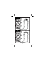
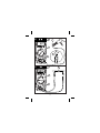
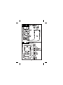
34XR-A
Professional Digital Multimeter
Users Manual
99 Washington Street
Melrose, MA 02176
Fax 781-665-0780
TestEquipmentDepot.com
34XR-A
1
5
2
MADE IN TAIWAN
PATENTS PENDING
www.amprobe.com
3
6
( )
( )
4
34XR-A
34XR-A Digital Multimeter
Safety Information ...........................................................................................2
Introduction .....................................................................................................3
Making Measurements.....................................................................................3
Verify Instrument Operation..........................................................................3
Range Selection ............................................................................................3
Correcting an Overload (o) Indication .........................................................3
Measuring DC Voltage ........................................... See Figure -1- ...............3
Measuring AC Voltage (True rms)............... See Figures -2- & -3- ...............4
Preparing for Current Measurements............................................................4
Measuring DC Current ........................................... See Figure -4- ...............4
Measuring AC Current (True rms)............... See Figures -3- & -5- ...............4
Measuring Resistance ........................................... See Figure -6- ...............5
Measuring Continuity............................................. See Figure -7- ...............5
Checking Diodes .................................................... See Figure -8- ...............5
Measuring Capacitance ......................................... See Figure -9- ...............5
Measuring Temperature ...................................... See Figure -10- ...............5
Measuring Frequency .......................................... See Figure -11- ...............6
Measuring Dutycycle .......................................... See Figure -12- ...............6
Additional Features ..........................................................................................6
Input Test Lead Warning...............................................................................6
True-rms Measurements ..............................................................................6
MIN MAX Measurements..............................................................................6
Auto Power Off .............................................................................................7
HOLD Measurements....................................................................................7
Backlight .......................................................................................................7
Product Maintenance .......................................................................................7
Battery and Fuse Replacement............................. See Figure -13- ...............7
Repair ..............................................................................................................8
WARRANTY ..................................................................................................9
Specifications ..................................................................................................9
1
Users Manual
Contents
•
•
•
•
•
•
•
•
Safety Information
The 34XR-A Digital Multimeter is UL, cUL, and EN61010-1 certified for
Installation Category III – 600V and Category II – 1000V. It is recommended for
use with local level power distribution, appliances, portable equipment, etc,
where only smaller transient overvoltages may occur, and not for primary
supply lines, overhead lines and cable systems.
Do not exceed the maximum overload limits per function (see specifications)
nor the limits marked on the instrument itself. Never apply more than 1000V
dc/750 V ac rms between the test lead and earth ground.
Inspect the DMM, test leads and accessories before every use. Do not use any
damaged part.
Never ground yourself when taking measurements. Do not touch exposed
circuit elements or test probe tips.
Do not operate the instrument in an explosive atmosphere.
Exercise extreme caution when: measuring voltage >20V // current >10mA // AC
power line with inductive loads // AC power line during electrical storms //
current, when the fuse blows in a circuit with open circuit voltage >1000 V //
servicing CRT equipment.
Always measure current in series with the load – NEVER ACROSS a voltage
source. Check fuse first. Never replace a fuse with one of a different rating.
Remove test leads before opening the Battery Cover or case.
Symbols Used in this Manual
B
T
F
B
P
I
Battery
Double insulated
Direct Current
Alternating Current
Complies with EU directives
Fuse
2
W
X
J
R
>
Refer to the manual
Dangerous Voltage
Earth Ground
Audible tone
Underwriters
Laboratories, Inc
Introduction
The 34XR-A is a True rms autoranging handheld digital multimeter for measuring
or testing the following:
• DC and AC voltage
• Temperature
• DC and AC current
• Capacitance
• Resistance
• Diodes
• Frequency
• Continuity
• Dutycycle
Additional features include: MIN MAX, HOLD, Backlight, and Range Lock
Making Measurements
Verify Instrument Operation
Before attempting to make a measurement, verify that the instrument is operational
and the battery is good. If the instrument is not operational, have it repaired before
attempting to make a measurement.
Range Selection
In addition to autoranging the 34XR-A allows you to manually select and lock a
range by pressing the RANGE button. RANGE appears on the display to indicate
that manual ranging is active. Each subsequent press of the range button steps the
meter to the next higher range. When the highest range is reached the next press
returns the meter to the lowest range. To return to autoranging press and hold the
RANGE button for 2 seconds. RANGE no longer shows on the display.
Use autorange for all initial measurements. Then, when appropriate, use the RANGE
button to select and lock a range.
Warning
To avoid electrical shock while manual ranging use the display
annunciators to identify the actual range selected.
Correcting an Overload (oor -o ) Indication W
An o indication may appear on the display to indicate that an overload condition
exists. For voltage and current measurements, an overload should be immediately
corrected by selecting a higher range. If the highest range setting does not
eliminate the overload, interrupt the measurement until the problem is identified
and eliminated. The o indication is normal for some functions; for example,
resistance, continuity, and diode test.
Measuring DC Voltage
1.
2.
3.
4.
5.
See Figure -1-
Set the Function Switch to v.
If RANGE is displayed, press the RANGE button to enable autoranging.
Connect the Test Leads: Red to E, Black to COM
Connect the Test Probes to the circuit test points.
Read the display, and, if necessary, correct any overload (o) conditions.
3
Measuring AC Voltage (True rms)
See Figures -2- & -3-
See Additional Features to find out the advantages of true rms.
1.
2.
3.
4.
5.
Set the Function Switch to V.
If RANGE is displayed, press the RANGE button to enable autoranging.
Connect the Test Leads: Red to E, Black to COM
Connect the Test Probes to the circuit test points
Read the display, and, if necessary, correct any overload (o) conditions.
Preparing for Current Measurements
•
•
•
•
•
Turn off circuit power before connecting the test probes.
Allow the meter to cool between measurements if current measurements
approach or exceeds 10 amps.
A warning tone sounds if you connect a test lead to a current input before you
select a current range.
Open circuit voltage at the measurement point must not exceed 1000 V.
Always measure current in series with the load. Never measure current across a
voltage source.
Measuring DC Current
1.
2.
3.
4.
5.
6.
7.
8.
See Figure -4-
Set the Function Switch to a A function and range.
If RANGE is displayed, press the RANGE button to enable autoranging.
Connect the Test Leads: Red to µA mA or 10A, Black to COM
Turn off power to the circuit being measured.
Open the test circuit (X) to establish measurement points.
Connect the Test Probes in series with the load.
Turn on power to the circuit being measured.
Read the display, and, if necessary, correct any overload (o) conditions.
Measuring AC Current (True rms)
See Figures -3- & -5-
See Additional Features to find out the advantages of true rms.
1. Set the Function Switch to a a function and range.
2. If RANGE is displayed, press the RANGE button to enable autoranging.
3. Connect the Test Leads: Red to µA mA or 10A, Black to COM
4. Turn off power to the circuit being measured.
5. Open the test circuit (X) to establish measurement points.
6. Connect the Test Probes in series with the load.
7. Turn on power to the circuit being measured.
8. Read the display, and, if necessary, correct any overload (o) conditions.
4
Measuring Resistance
See Figure -6-
Set the Function Switch to Ω.
If RANGE is displayed, press the RANGE button to enable autoranging.
Connect the Test Leads: Red to E, Black to COM
Turn off power to the circuit being measured. Never measure resistance across
a voltage source or on a powered circuit.
5. Discharge any capacitors that may influence the reading.
6. Connect the Test Probes across the resistance.
7. Read the display. If o appears on the highest range, the resistance is too large
to be measured.
1.
2.
3.
4.
Measuring Continuity
1.
2.
3.
4.
5.
6.
See Figure -7-
Set the Function Switch to R.
Connect the Test Leads: Red to E, Black to COM
Turn off power to the circuit being measured.
Discharge any capacitors that may influence the reading.
Connect the Test Probes across the resistance.
Listen for the tone that indicates continuity (< 35 Ω).
Checking Diodes
1.
2.
3.
4.
5.
6.
See Figure -8-
Set the Function Switch to G.
Connect the Test Leads: Red to E, Black to COM
Turn off power to the circuit being measured.
Free at least one end of the diode from the circuit.
Connect the Test Probes across the diode.
Read the display. A good diode has a forward voltage drop of about 0.6 V. An
open or reverse biased diode will read o.
Measuring Capacitance
See Figure -9-
1.
2.
3.
4.
5.
6.
Set the Function Switch to an appropriate µF function and range.
Connect the Test Leads: Red to COM, Black to µA mA P(-)
Turn off power to the circuit being measured.
Discharge the capacitor using a 100 kΩ resistor.
Free at least one end of the capacitor from the circuit.
Connect the Test Probes across the capacitor. When measuring an electrolytic
capacitor match the test lead polarity to the polarity of the capacitor.
7. Read the display.
Measuring Temperature
See Figure -10-
1. Set the Function Switch to °C or °F.
2. Connect the K-type thermocouple to a TEMP adapter (XR-TA).
Match the polarity of the adapter to the polarity of the thermocouple.
3. Connect the TEMP adapter to the E and COM inputs.
Note: The 34XR-A is compatible with all K-type thermocouples. The K-type bead
thermocouple supplied with the meter is not intended for contact with liquids or electrical
circuits.
4. Expose the thermocouple to the temperature to be measured.
5. Read the display.
5
Measuring Frequency
1.
2.
3.
4.
See Figure -11-
Set the Function Switch to Hz.
Connect the Test Leads: Red to Hz, Black to COM
Connect the Test Probes to the signal source.
Read the display. The Meter will autorange for the best resolution.
Measuring Dutycycle
1.
2.
3.
4.
See Figure -12-
Set the Function Switch to %.
Connect the Test Leads: Red to %, Black to COM
Connect the Test Probes to the signal source.
Read the display. The Meter will autorange for the best resolution.
Additional Features
Input Test Lead Warning
The meter emits a continuous tone when a test lead is placed in the µA mA or 10A
input jack and the Function/Range Switch is not set to a correct current position. (If
the meter is connected to a voltage source with leads connected for current, very
high current could result). All current ranges are protected by fast acting fuses.
True-rms Measurements
For ac measurements most DMMs average the ac input signal and display the
result as an estimated rms value. This average-responding method is accurate for
sinusoidal waveforms, but can be very inaccurate for distorted waveforms. To
ensure the most accurate measurements, always use a true-rms DMM when
measuring ac voltage or ac current on circuits for the following kinds of
applications:
• Power Supplies - diodes
• Controllers
• Power Limiting - SCR or Triac
• Starting - motors
• Florescent Lighting - ballasts
• Speed Control - motors
• Pulsed Signals
• Any non-sinusoidal ac waveform
MIN MAX Measurements
The MIN MAX function reads and updates the display to show the maximum or
minimum value measured after you press the MIN MAX button.
Pressing the MIN MAX button for less than 1 second will put the meter into a mode
of displaying the maximum, minimum, or actual readings. Each time the button is
pressed, the meter will cycle to the next display mode as shown in the table below.
Press the MIN MAX button for more than 2 seconds to exit MIN MAX.
Button
< 1 second
< 1 second
< 1 second
> 2 seconds
Display
MAX
MIN
MIN MAX (blinks)
Exit MIN MAX
Value Displayed
Maximum value after feature activated
Minimum value after feature activated
Normal measurement, actual reading
Normal measurement, actual reading
6
Auto Power Off
Auto Power Off is a battery saving feature that puts the meter into a sleep mode if
the Function/Range Switch has not changed position in the last 30 minutes. To
wake the meter turn it off and then on.
The Auto Power Off feature can be disabled to keep the meter from going to sleep.
This feature is useful when using the MIN MAX mode for extended periods. To
disable the Auto Power Off feature use the following procedure:
1. Set the Function Switch to OFF.
2. Press and hold the MIN MAX button while turning the Function Switch to the
desired function.
3. Continue to press the MIN MAX button until the display finishes this
initialization period and the reading settles.
4. Release the MIN MAX button. The Auto Power Off feature will remain disabled
until the meter is turned off and then on.
HOLD Measurements
The HOLD button causes the meter to capture and continuously display a
measurement reading. To use the HOLD feature make a measurement, and then,
after the reading has stabilized, momentarily press the HOLD button. You can
remove the test leads and the reading will remain on the display. Pressing the
HOLD button again releases the display.
Backlight
Pressing the L button illuminates the display with a blue backlight. The backlight
will automatically turn off in about 60 seconds. Frequent use of the backlight will
decrease battery life.
Product Maintenance
Cleaning
To clean the meter, use a soft cloth moistened with water. To avoid damage to the
plastic components do not use benzene, alcohol, acetone, ether, paint thinner,
lacquer thinner, ketone or other solvents to clean the meter.
Troubleshooting
If the meter appears to operate improperly, check the following items first.
1. Review the operating instructions to ensure the meter is being used properly.
2. Inspect and test the continuity of the test leads.
3. Make sure the battery is in good condition. The low battery symbol B appears
when the battery falls below the level where accuracy is guaranteed. Replace a
low-battery immediately.
4. Check the condition of the fuses if the current ranges operate incorrectly.
Battery and Fuse Replacement
See Figure -13-
XWWARNING
To avoid electrical shock remove the test leads from both the
meter and the test circuit before accessing the battery or the
fuses.
7
Specifications
General Specifications
Display: 3 ¾ digit liquid crystal display
(LCD)(3999 count) with a 41-segment
analog bar-graph.
Polarity: Automatic, positive implied,
negative polarity indication. Overrange: (0o)
or (-0o) is displayed.
Zero: Automatic.
Low battery indication: The B is
displayed when the battery voltage drops
below the operating level.
Auto power off: Approx. 30 minutes.
Measurement rate: 2 times per second,
nominal.
Operating environment: 0 °C to 50 °C at
<70 % R.H.
Storage temperature: -20 °C to 60 °C, 0
to 80 % R.H. with battery removed from
meter.
Temperature Coefficient: 0.1 ×
(specified accuracy) per °C. (0 °C to 18 °C,
28 °C to 50 °C).
Altitude: 2000 m (6562 feet)
Power: Single standard 9-volt battery,
NEDA 1604, JIS 006P, IEC 6F22.
Battery life: 100 hours typical with
carbon-zinc. 200 hours typical with alkaline.
Frequent use of the backlight will decrease
battery life.
Dimensions: 196 mm (H) × 92 mm (W) ×
60 mm (D).
Weight: Approximately 400 g including
battery.
Box contents:
The 34XR-A includes the following items:
Test leads w/ alligator clips 1 set
1
Holster
1
Magnet Strap
1
Temperature Adapter
1
K-type thermocouple
1
Users Manual
1
9 V battery (installed)
mA fuse, 0.315 A/ 1000 V 1 spare
Approvals:
>
LISTED
950Z
P
Safety: Conforms to UL1244; EN61010-1:
Cat II - 1000V / Cat III - 600V; Class 2,
Pollution degree II.
EMC: Conforms to EN61326-1, criteria B
This product complies with requirements of
the following European Community
Directives: 89/ 336/ EEC (Electromagnetic
Compatibility) and 73/ 23/ EEC (Low
Voltage) as amended by 93/ 68/ EEC (CE
Marking). However, electrical noise or
intense electromagnetic fields in the vicinity
of the equipment may disturb the
measurement circuit. Measuring
instruments will also respond to unwanted
signals that may be present within the
measurement circuit. Users should exercise
care and take appropriate precautions to
avoid misleading results when making
measurements in the presence of electronic
interference.
Electrical Specifications
(Accuracy at 23 °C ±5 °C, <75 % relative
humidity)
DC VOLTS
Ranges: 400mV, 4V, 40V, 400V, 1000V
Resolution: 100 µV in 400mV range
Accuracy: ±(0.5 % rdg + 1 dgt)
Input impedance:
400mV: >100 MΩ; 4V: 10 MΩ; 40V to
1000V: 9.1 MΩ
Overload protection: 1000 V dc /
750 Vac rms
AC VOLTS true rms (45Hz - 2kHz)
Ranges: 400m, 4V, 40V, 400V, 750V
Resolution: 100 µV
Accuracy:
±(1.2 % rdg +8 dgts) 45 Hz to 100 Hz on
400mV range
±(1.2 % rdg + 8 dgts) 45 Hz to 500 Hz
±(2.0 % rdg +8 dgts) 500 Hz to 2 kHz
±(2.0 % rdg + 8 dgts) 45 Hz to 1 kHz on
750 V range
Crest Factor: ≤ 3
Input impedance: 400mV: >100 MΩ;
4V: 10 MΩ; 40V to 1000V: 9.1 MΩ
AC coupled true rms specified from
5 % to 100 % of range
Overload protection: 1000 V dc or
750 V ac rms
DC CURRENT
Ranges: 400µA, 4000µA, 40mA, 300mA,
10A
Resolution: 0.1µA
Accuracy: ±(1.0 % rdg + 1 dgt) on 400µA to
300mA ranges
±(2.0 % rdg + 3 dgts) on 10A range
Burden voltage:
400 µA Range:
1 mV/ 1 µA
4 mA Range:
500 mV/ 1 mA
40 mA Range:
10 mV/ 1 mA
300 mA:
8 mV/ 1 mA
10A:
40 mV/ 1 A
Input protection: 0.315A/1000V fast blow
ceramic fuse 6.3×32mm on µA/mA input
10A/1000V fast blow ceramic fuse
10×38mm on 10A input
10A input: 10 A for 5 minutes maximum
followed by a 10 minute cooling period
AC CURRENT true rms (45Hz - 1kHz)
Ranges: 400µA, 4000µA, 40mA, 300mA,
10A
Resolution: 0.1 µA
Accuracy: ±(1.5 % rdg + 8 dgts) on 400µA
to 300mA ranges
±(2.5 % rdg + 10 dgts) on 10A range
Crest Factor: ≤ 3
Burden Voltage: See DC Current
Input protection: 0.315A/1000V fast blow
ceramic fuse 6.3×32mm on µA/mA input
10A/1000V fast blow ceramic fuse
10×38mm on 10A input
10A input: 10 A for 4 minutes maximum
followed by a 12 minute cooling period
10
RESISTANCE
DUTY CYCLE
Ranges: 400Ω, 4kΩ, 40kΩ, 400kΩ, 4MΩ,
40MΩ
Resolution: 100 mΩ
Accuracy: ±(1.0 % rdg + 4 dgts) on
400Ω to 4MΩ ranges
±(2.0 % rdg + 5 dgts) on 40MΩ range
Open circuit volts: -0.45 V dc typical,
(-1.2 V dc on 400Ω range)
Overload protection: 1000 V dc or
750 V ac rms
Ranges: 0 to 90 %
Resolution: 0.1 %
Pulse widh: >10 µs
Frequency range: 40 Hz to 20 kHz
Accuracy: (5V logic ) ±(2.0% rdg + 5 dgts)
Overload protection: 1000 V dc or
750 V ac rms
CONTINUITY
Audible indication: < 35 Ω
Response time: 100 ms
Overload protection:1000 V dc or
750 V ac rms
CAPACITANCE
Ranges: 4µF, 40µF, 400µF, 4000µF
Resolution: 1 nF
Accuracy:
±(5.0 % rdg + 10 dgts) on 4µF range
±(5.0 % rdg + 5 dgts) on 40µF to
400µF ranges
±(5.0 % rdg + 15 dgts) on 4000µF range
Test voltange: < 3.0 V
Test Frequency: 25Hz
Input protection: 0.315A/1000V fast blow
ceramic fuse 6.3×32mm on µA/mA input
DIODE TEST
Test current: approximately 1.2 mA
Accuracy: ±(1.5 % rdg + 3 dgts)
Resolution: 1 mV
Open circuit volts: 3.0 V dc typical
Overload protection: 1000 V dc or
750 V ac rms
ADDITIONAL FEATURES
µA mA, 10A Test Lead Connection: Beeps
TEMPERATURE
Ranges: -20 °C to 1000 °C, -4 °F to 1832 °F
Resolution: 1 °C, 1 °F
Accuracy:
±(2.0 % rdg + 4 °C) -20 °C to 10 °C
±(1.0 % rdg + 3 °C) 10 °C to 200 °C
±(3.0 % rdg + 2 °C) 200 °C to 1000 °C
±(2.0 % rdg + 8 °F) -4 °F to 50 °F
±(1.0 % rdg + 6 °F) 50 °F to 400 °F
±(3.0 % rdg + 4 °F) 400 °F to 1832 °F
Overload protection: 1000 V dc or
750 V ac rms
FREQUENCY
Ranges: 4k, 40k, 400k, 4M, 40MHz
Resolution: 1 Hz
Accuracy: ±(0.1 % rdg + 3 dgts)
Sensitivity:
10 Hz to 4 MHz: >1.5 V ac rms;
4 MHz to 40 MHz: >2 V ac rms, <5 V ac rms
Minimum pulse width: > 25 ns
Duty cycle limits: > 30 % and < 70 %
Overload protection: 1000 V dc or
750 V ac rms
11
to warn test leads are connected to
measure current while Function/Range
Switch is not set to a measure current.
MIN MAX: Displays the minimum or
maximum value detected while making a
measurement.
HOLD: Holds the latest reading on the
display.
RANGE: Manual range mode.
Backlight: Backlight auto-off
approximately 60 seconds
Auto Power off: 30 minutes, typical
REPLACEMENT PARTS
TL36 Test Lead Set with Alligator clips
FP300 mA fuse - Fuse Pack .315A/1000V
(4 each)
FP100 10A fuse - Fuse Pack 10A/1000V
(2 each)
XR-TA Input Adapter for K-type
thermocouple
TP255 K type thermocouple
®
XR-H2 Magne-Grip Holster, clip, magnet,
and strap
1
V
34XR-A
4
5
2
1
%
3
( )
( )
2
V
34XR-A
4
5
2
1
3
( )
( )
12
Input Waveform
Signal d'entrée
Eingangsschwingungsform
Forma d'onda d'ingresso
Forma de onda de entrada
Sine Wave
Sinusoïdale
Sinusschwingung
Onda sinusoidale
Onda sinusoidal
Full Wave, Sine Wave
Onde complète, Sinusoïdale
Volle Schwingung, Sinusschwingung
Onda sinusoidale, onda intera
Onda completa, Onda sinusoidal
Half-Wave, Sine Wave
Demi-onde, sinusoïdale
Halbschwingung, Sinusschwingung
Onda sinusoidale, semionda
Media onda, onda sinusoidal
Square Wave
Onde carrée
Rechteckschwingung
Onda quadra
Onda cuadrada
Square Wave
Onde carrée
Rechteckschwingung
Onda quadra
Onda cuadrada
Pulse Wave
Onde impulsionnelle
Impulsschwingung
Onda delI'impulso
Onda de impulsos
Sawtooth Wave
Onde en dent de scie
Sägezahnschwingung
Onda a denti di sega
Onda diente de sierra
13
34XR-A
4
A
34XR-A
8
4
2
7
5
1
6
3
( )
( )
5
A
34XR-A
8
4
2
7
5
1
%
3
6
( )
( )
14
6
7
34XR-A
5
4
2
6
1
3
( )
( )
7
34XR-A
5
1
3
2
( )
( )
4
6
15
8
3
6
34XR-A
4
1
5
2
( )
( )
9
7
34XR-A
1
6
3
( )
( )
4
2
5
16
10
5
4
34XR-A
1
2
K
3
( )
( )
11
4
3
34XR-A
1
2
( )
( )
17
12
4
34XR-A
1
2
( )
3
( )
13
(2)
(2)
18
(4)