1
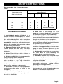
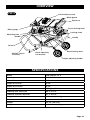
15A Jobsite Table Saw
240-0035
OPERATOR’S MANUAL
CAUTION: To Reduce The Risk Of Injury, User Must
Read And Understand Operator’s Manual. Save These
Instructions For Future Reference.
Page 1
table of contents
Safety Symbols. . . . . . . . . . . . . . . . . . . . . . . . . . . . . . . . . . . . . . . . . . . . . . . . . . . . . . . . . . Page 2
Safety Instructions. . . . . . . . . . . . . . . . . . . . . . . . . . . . . . . . . . . . . . . . . . . . . . . . . . . . . . . Page 3
Overview / Specifications . . . . . . . . . . . . . . . . . . . . . . . . . . . . . . . . . . . . . . . . . . . . . . . . Page 10
Assembly . . . . . . . . . . . . . . . . . . . . . . . . . . . . . . . . . . . . . . . . . . . . . . . . . . . . . . . . . . . . . Page 11
Operation . . . . . . . . . . . . . . . . . . . . . . . . . . . . . . . . . . . . . . . . . . . . . . . . . . . . . . . . . . . . . Page 22
Maintenance. . . . . . . . . . . . . . . . . . . . . . . . . . . . . . . . . . . . . . . . . . . . . . . . . . . . . . . . . . . Page 34
Troubleshooting. . . . . . . . . . . . . . . . . . . . . . . . . . . . . . . . . . . . . . . . . . . . . . . . . . . . . . . . Page 35
safety symbols
Some of these following symbols may be used on this tool. Please study them and learn their
meaning. Proper interpretation of these symbols will allow you to operate the tool better and
safer.
Symbol
Name
Designation / Explanation
V
Volts
Voltage
A
Amperes
Current
Hz
Hertz
Frequency (cycles per second)
W
Watts
Power
∿
Alternating current
Type of current
�
Direct current
Type of characteristic of current
no
No-load speed
Rotational speed at no load
Class II construction
Double insulated construction
Per minute
Revolutions, strokes, surface speed
orbits, etc., per minute
.../min
Wear safety goggles
WARNING: The operation of any
power tool can result in foreign objects
being thrown into your eyes, which can
result in severe eye damage. Before
beginning power tool operation, always
wear safety goggles or safety glasses
with side shields and a full-face shield
when needed. We recommend a Wide
Vision Safety Mask for use over eyeglasses or standard safety glasses with
side shields. Always use eye protection
which is marked to comply with
ANSI Z87.1.
WARNING: To ensure safety and reliability, all repairs should be performed by a
qualified service technician.
Page 2
safety INSTRUCTIONS
The purpose of safety symbols is to attract your attention to possible dangers. The
safety symbols and the explanations with them deserve your careful attention and
understanding. The symbol warnings do not, by themselves, eliminate any danger. The
instructions and warnings they give are no substitutes for proper accident prevention
measures.
WARNING: Be sure to read and understand all safety instructions in this manual,
including all safety alert symbols such as “DANGER,” ”WARNING,” and “CAUTION”
before using this tool. Failure to following all instructions listed below may result in
electric shock, fire, and/or serious personal injury.
SYMBOL MEANING
SAFETY ALERT SYMBOL: Indicates DANGER, WARNING, OR CAUTION.
May be used in conjunction with other symbols or pictographs.
DANGER: Indicates an imminently hazardous situation, which, if not avoided,
will result in death or serious injury.
WARNING: Indicates a potentially hazardous situation, which, if not avoided,
could result in death or serious injury.
CAUTION: Indicates a potentially hazardous situation, which, if not avoided,
could result in minor or moderate injury.
NOTICE: (Without Safety Alert Symbol) Indicates a situation that may result in property
damage.
SAVE THESE INSTRUCTIONS!
Page 3
safety INSTRUCTIONS
RULES FOR SAFE OPERATION
KNOW THE TOOL
To reduce the risk of injury, user must read
instruction manual.
IMPORTANT
This tool should only be serviced by a
qualified service technician. For more
information, call the toll-free helpline:
1-866-917-4374.
GENERAL SAFETY RULES
FOR BENCH TOOLS
WARNING: To reduce the risk of
injury, the user must read the Operator’s
Manual.
WARNING: Read all safety
warnings and instructions! Failure to
follow the warnings and instructions may
result in electric shock, fire and / or
serious injury. Save all warnings and
instructions for future reference.
1) Keep guards in place and in working
order.
2) Remove adjusting keys and wrenches.
Form a habit of checking to see that keys
and adjusting wrenches are removed from
the tool before turning it on.
3) Keep work area clean. Cluttered areas
and benches invite accidents.
4) Don’t use in dangerous environments.
Don’t use power tools in damp or wet
locations or expose them to rain. Keep the
work area well lighted.
5) Keep children away. All visitors should
be kept a safe distance from the work area.
6) Make the workshop childproof with
padlocks and master switches or by
removing starter keys.
7) Don’t force the tool. It will do the job
better and more safely when it is used at the
rate at which it was designed to work.
8) Use the right tool. Don’t force the tool
or attachment to do a job that it was not
designed to do.
9) Use the proper extension cord. Make
sure that your extension cord is in good
condition. When using an extension cord,
be sure to use one that is heavy enough
to carry the current that your product will
draw. An undersized cord will cause a drop
in line voltage, resulting in loss of power and
overheating. Table 1 shows the correct size
to use, depending on the cord length and
the nameplate amperage rating. If in doubt,
use the next heavier gauge. The smaller the
gauge number, the heavier the cord.
10) Wear the proper apparel. Do not wear
loose clothing, gloves, neckties, rings,
bracelets, or other jewelry that can get
caught in moving parts. Non-slip footwear
is recommended. Wear protective hair
covering to contain long hair.
11) Always use safety glasses. Also use a
facemask or dust mask if the cutting
operation is dusty. Everyday eyeglasses
only have impact-resistant lenses. They are
NOT safety glasses.
12) Secure the workpiece. Use clamps or a
vise to hold the workpiece when practical.
It’s safer than using your hand and it frees
both hands to operate the tool.
13) Don’t overreach. Keep proper footing
and balance at all times.
14) Maintain tools with care. Keep tools
sharp and clean for best and safest
performance. Follow instructions for
lubricating and changing accessories.
15) Disconnect tools before servicing and
when changing accessories, such as blades,
bits, cutters, and the like.
16) Reduce the risk of unintentional starting.
Make sure that the switch is in the OFF
position before plugging in the tool.
17) Use recommended accessories. Consult
the Operator’s Manual for recommended
accessories.
The
use
of
improper
accessories may cause a risk of injury to
persons.
18) Never stand on the tool. Serious injury
could occur if the tool is tipped or contacted
unintentionally.
Page 4
safety INSTRUCTIONS
19) Check damaged parts. Before further
use of the tool, any guard or other part that
is damaged should be carefully checked to
determine whether it will operate properly
and perform its intended function. Check
for misalignment or binding of moving parts,
broken parts or mountings, and any other
condition that may affect the operation
of the tool. A guard or other part that is
damaged should be properly repaired or
replaced.
20) Direction of feed: Always feed the
workpiece into the blade or cutter against
the direction of rotation of the blade or
cutter.
21) Never leave the tool running while
unattended. Turn the power off. Don’t leave
the tool until it comes to a complete stop.
SPECIFIC SAFETY RULES
1) Guard against kickback. Kickback
occurs when the blade stalls rapidly and
the workpiece is driven back toward the
operator. It can pull your hand into the blade,
resulting in serious personal injury. Stay out
of the blade path, and turn the switch OFF
immediately if the blade binds or stalls.
2) Use rip fence. Always use a fence or
straight edge guide when ripping.
3) Support large panels. To minimize the
risk of blade pinching and kickback, always
support large panels.
4) Always use the blade guard, spreader,
and
anti-kickback
pawls
on
all
“throughsawing” operations. Throughsawing operations are those in which the
blade cuts completely through the workpiece,
as in ripping or crosscutting. Keep the blade
guard and the anti-kick-back pawls down,
and keep the riving knife/spreader/splitter
properly aligned with the saw blade.
5) Always secure work firmly against rip
fence, miter fence, or miter gauge.
Page 5
6) Always use a push stick for ripping
narrow stock. A push stick is a device that
is used to push a workpiece through the
blade instead of using your hands. Size and
shape can vary, but the push stick must
always be narrower than the workpiece in
to prevent the push stick from contacting
the saw blade. When ripping narrow stock,
always use a push stick so that your hand
does not come within 3” (7.6 cm) of the saw
blade. Use a feather board and push blocks
for all non-through cuts.
7) Never
perform
any
operation
“freehand.” Freehand means use only
your hands to support or guide the
workpiece, which is dangerous. Always
use either the rip fence or miter fence
to position and guide the work.
8) Never stand or have any part of your
body in line with the path of the saw blade.
9) Never reach behind, over, or within
3” (7.6 cm) of the blade or cutter with
either hand for any reason.
10) Always remove the rip fence from the
saw when crosscutting.
11) Do not use the miter gauge and rip fence
during the same operation. Never use the
rip fence as cut-off gauge when
crosscutting.
12) Never attempt to free a stalled saw
blade without first turning the saw off
and disconnecting the saw from the
power source.
13) Provide adequate support to the rear
and sides of the saw table for wide or
long workpieces. Use a sturdy “outrigger”
support if an extension table of more than
24” (61 cm) long is attached to the saw.
14) Avoid kickbacks (work thrown back
toward you) by:
A) Keeping the blade sharp.
B) Keeping the rip fence parallel to the saw
blade.
C) Keeping the riving knife/spreader/
splitter, anti-kickback pawls, and blade
guard in place and operating properly.
safety INSTRUCTIONS
D) Not releasing the work before it is
pushed all the way past the saw blade
using a push stick.
E) Not ripping work that is twisted or
warped or that does not have a straight
edge to guide along the fence.
15) Avoid awkward operations and hand
positions where a sudden slip could cause
your hand to move into the cutting tool.
16) Use only recommended accessories
listed in this Operator’s Manual or
addendums. The use of accessories that
are not listed may cause a risk of personal
injury. Instructions for safe use of
accessories are included with the
accessory.
17) Make sure that the work area has
ample lighting to see the work, and that no
obstructions will interfere with safe
operation before performing any work
using the table saw.
18) Always turn the saw off before
disconnecting it to avoid accidental
starting when reconnecting to the power
supply.
WARNING: For your own safety,
read the Operator’s Manual before
operating the saw.
19) Wear eye protection.
20) Use the saw-blade guard and spreader
for every operation for which it can be
used, including all through-sawing.
21) Keep hands out of the line of the saw
blade.
22) Pay particular attention to instructions
for reducing the risk of kickback.
23) Do not perform any operation freehand.
24) Never reach around or over the saw
blade.
25) Do not expose to rain or use in a damp
location.
26) Use the saw-blade guard and spreader
for every operation for which they can be
used, including all through-sawing.
27) Keep the handle out of the line of the
saw blade.
28) Use a push-stick when required.
29) Disconnect the tool and be sure the
blade has come to a complete stop before
servicing or adjusting.
30) Save these instructions. Refer to them
frequently, and use to instruct other users. If
you lend someone this tool, lend them these
instructions also.
31) Protect your hearing. Wear hearing
protection during periods of extended
operation. Following this rule will reduce the
risk of serious personal injury.
WARNING: Some dust created by
power sanding, sawing, grinding, drilling,
and other construction activities contains
chemicals that are known to cause
cancer, birth defects or other reproductive
harm.
Some examples of these chemicals are:
• Lead from lead-based paints.
• Crystalline silica from bricks and cement
and other masonry products.
• Arsenic and chromium from chemically
treated lumber.
Your risk of exposure to these chemicals
varies depending on how often you do this
type of work. To reduce your exposure to
these chemicals, work in a well-ventilated
area, and work with approved safety
equipment, such as dust masks that are
specially designed to filter out microscopic
particles.
Page 6
safety INSTRUCTIONS
ELECTRICAL SAFETY (FIG.1)
FIG. 1
Repair or replace a damaged or worn
cord immediately.
Permanently connected tools: This tool
should be connected to a grounded metal
permanent wiring system or to a system that
has an equipment-grounding conductor.
GUIDELINES FOR
EXTENSION CORDS
Grounding pin
120V Grounded
outlet
Grounding instructions: In the event of
a malfunction or breakdown, grounding
provides the path of least resistance for
electrical current in order to reduce the risk
of electric shock. This tool is equipped with
an electric cord that has an equipmentgrounding conductor and a grounding
plug. The plug must be plugged into a
matching outlet that is properly installed
and grounded in accordance with all local
codes and ordinances.
Do not modify the plug provided. If it will
not fit into the outlet, have a proper outlet
installed by a qualified electrician.
Improper connection of the equipmentgrounding conductor can result in a risk of
electric shock. The insulated conductor that
has a green outer surface, with or without
yellow stripes, is the equipment-grounding
conductor. If repair or replacement of
the electric cord or plug is necessary, do
not connect the equipment-grounding
conductor to a live terminal. Check with a
qualified electrician or service technician
if the grounding instructions are not
completely understood, or if in doubt as
to whether the tool is properly grounded.
Use only 3-wired extension cords that have
3-pronged grounding plugs and 3-holed
receptacles that accept the tool’s plug.
Page 7
Use a proper extension cord. Make sure
extension cords are in good condition.
When using an extension cord, be sure to
use a cord that is heavy enough to carry
the drawn current needed by the saw. An
undersized cord will cause a drop in line
voltage, resulting in loss of power and
overheating. The table below shows the
correct size to use, depending on the cord
length and nameplate amperage rating. If
in doubt, use the next heavier gauge. The
smaller the gauge number, the heavier
the cord.
Be sure extension cords are properly wired
and in good condition. Always replace a
damaged extension cord or have it repaired
by a qualified technician before using it.
Protect extension cords from sharp objects,
excessive heat, and damp or wet areas.
Use a separate electrical circuit for power
tools. This circuit must not be less than
#6 wire, and should be protected with a
time-delayed fuse. Before connecting the
tool to the power line, make sure the switch
is in the OFF position and the electric current
is rated the same as the current stamped
on the motor’s nameplate. Running at a
lower voltage will damage the motor.
safety INSTRUCTIONS
Recommended size of extension cords
Table 1
Amperage rating
of tool
(120 V circuit only)
Total length of the
extension cord
25’
50’
100’
150’
More than
Not more than
Minimum Gauge for the extension cord (AWG)
0
6
18
16
16
14
6
10
18
16
14
12
10
12
16
16
14
12
12
16
14
12
Glossary of terms
1. Anti-kickback pawls: Kickback is a
hazard in which the workpiece is thrown
back toward the operator. The teeth on
the anti-kickback pawls point away from
the workpiece. If the workpiece should be
pulled back toward the operator, the teeth
dig into the wood to help prevent or reduce
the possibility of kickback.
2. Spreader/Riving Knife: A metal piece,
slightly thinner than the blade, that helps
to keep the kerf open and helps to prevent
kickback.
3. Arbor: The shaft on which a blade or
cutting tool is mounted.
4. Ripping or Rip Cut: A cutting operation
along the length of the workpiece.
5. Bevel Cut: A cutting operation made
with the blade at any angle other than
90° to the table surface.
6. Compound Cut: A crosscut made with
both a miter angle and a bevel angle.
7. Crosscut: A cutting or shaping operation
made across the grain or width of the
workpiece.
8. Miter Cut: A cutting operation made
with the workpiece at any angle other
than 90° to the blade.
Not recommended
9. Dado Cut: A non-through cut that
produces a square-sided notch or trough in
the workpiece (requires a special blade).
10. Non-Through Cut: Any cutting operation
where the blade does not extend completely
through the thickness of the workpiece.
11. Through-sawing: Any cutting operation
where the blade extends completely through
the thickness of the workpiece.
12. Freehand: Performing a cut without the
workpiece being guided by a fence, miter
gauge, or other aid. Never perform any cut
freehand with this saw.
13. Kickback: A hazard that can occur when
the blade binds or stalls, throwing the
workpiece back toward the operator.
14. Push Stick: A push stick should be used
for narrow ripping operations. These aids
help to keep the operator’s hands well
away from the blade.
15. Worktable: Surface where the workpiece
rests while performing a cutting, drilling,
planning, or sanding operation.
16. Kerf: The material removed by the blade
in a through-cut, or the slot produced by the
blade in a non-through or partial cut.
Page 8
safety INSTRUCTIONS
17. Bevel scale: The easy-to-read scale on
the front of the table saw cabinet shows the
exact blade angle.
18. Blade: For maximum performance, use
of the 10” (25.4 cm) carbide-tipped
combination blade provided with this saw
is recommended. The blade is raised and
lowered with the height-adjusting handle.
Bevel angles are locked using the bevellocking lever. Additional blade styles of the
same high quality are available for specific
operations, such as ripping.
WARNING: Do not use blades
rated less than the speed of this tool.
Failure to heed this warning could result in
personal injury.
19. Blade guard: Always keep the guard
down over the blade for through-sawing
cuts.
20. Bevel-locking lever: Located under the
worktable surface on the front of the
cabinet, this lever locks the angle setting of
the blade.
21. Height-adjusting handle: Located on the
front of the cabinet, this knob is used to
lower and raise the blade for adjustments or
blade replacement.
22. Bevel-adjusting hand wheel: Located on
the front of the cabinet, the hand wheel
makes adjusting for bevel angles easy.
23. Fence-locking lever: The lever on the
front of the rip fence releases the rip fence
or locks it in place.
24. Miter gauge: This miter gauge aligns the
wood for a crosscut. The easy-to-read
indicator shows the exact angle for a miter
cut, with positive stops at 0˚ and 45˚.
25. Miter gauge grooves: The miter gauge
rides in these grooves on either side of the
blade.
26. Rip fence: A sturdy metal fence that
guides the workpiece, and is secured with
the locking lever.
27. Scale: Located on the front rail, the
easy-to-read
scale
provides
precise
measurements for rip cuts.
Page 9
28. Sliding table extension: Located on the
right side of the saw table, this extension
table gives the operator additional support
when cutting wide workpieces.
29. On/Off switch assembly: This saw has an
easy access switch. To lock the switch in the
OFF position, remove the yellow switch key
from the switch. Place the key in a location
that is inaccessible to children and others
who are not qualified to use the tool.
overview
FIG. 2
Anti-kickback pawls
Blade guard
Rip fence
Fence-locking lever
Miter gauge
Locking knob
Mounting hole
Handle
Handle
Stand
ON/OFF switch
assembly
Bevel-adjusting
hand wheel
Bevel-locking lever
Height-adjusting handle
Specifications
Motor
120 V, 60 Hz, 15 A
Rated speed
4000 RPM
Wheel Diameter
10”
Depth of cut at 0°
3 1/4”
Depth of cut at 45°
2 1/4”
Ripping Capacity
25” right, 9” left
Tabletop with extension
34” x 21 1/2”
Tabletop without extension
27” x 21 1/2”
Weight without stand
50lbs. 2oz. (22.8kg)
Stand
Height
22 7/8” (58.1cm)
Weight
30lbs. 7oz. (13.8kg)
Page 10
assembly
Contents
Blade guard . . . . . . . . . . . . . . . . . . . . 1 pc
Anti-kickback pawls. . . . . . . . . . . . . . 1 pc
Miter gauge. . . . . . . . . . . . . . . . . . . . . 1 pc
Rip fence. . . . . . . . . . . . . . . . . . . . . . . 1 pc
Push stick. . . . . . . . . . . . . . . . . . . . . . 1 pc
Blade wrench. . . . . . . . . . . . . . . . . . . 1 pc
Dado throat insert. . . . . . . . . . . . . . . . 1 pc
Hex key (15/64” (6mm) . . . . . . . . . . . 1 pc
Hex key (3/16” (5mm). . . . . . . . . . . . . 1 pc
Hex key (5/32” (4mm) . . . . . . . . . . . . 1 pc
Bolts . . . . . . . . . . . . . . . . . . . . . . . . . 4 pcs
Nuts. . . . . . . . . . . . . . . . . . . . . . . . . . 4 pcs
Washer . . . . . . . . . . . . . . . . . . . . . . . 8 pcs
UNPACKING
This product requires assembly.
1. Carefully lift the saw from the carton
and place it on a level work surface.
2. Inspect the tool carefully to make sure
that no breakage or damage occurred
during shipping.
3. Do not discard the packing material
until you have carefully inspected and
satisfactorily operated the tool.
4. The saw is factory set for accurate
cutting. After assembling it, check for
accuracy. If shipping has influenced the
settings, refer to specific procedures
explained in this Operator’s Manual.
5. If any parts are damaged or missing,
please
call
1-800-689-9928
for
assistance.
If any parts are damaged or missing, do not
operate this tool until the parts are replaced.
WARNING: If any parts are
damaged or missing, do not operate this
tool until the parts are replaced. Failure
to heed this warning could result in
serious personal injury.
Page 11
WARNING: Do not attempt to
modify this tool or create accessories not
recommended for use with this tool. Any
such alteration or modification is misuse,
and could result in a hazardous condition
leading to possible serious personal
injury.
WARNING: Do not connect to the
power supply until assembly is complete.
Failure to comply could result in
accidental starting and possible serious
personal injury.
WARNING: Never stand directly in
line with the blade or allow hands to come
within 3” (7.6 cm) of the blade. Do not
reach over or across the blade. Failure to
heed this warning can result in serious
personal injury.
WARNING: To avoid serious
personal injury, always make sure the
table saw is securely mounted to a
workbench or an approved leg stand.
NEVER operate the saw on the floor.
STAND SET-UP
The saw can be used for cutting operations
using the stand.
assembly
OPEN THE STAND (FIG. 3, 4, 5)
FIG. 5
Keep body clear of hinge points when
opening or closing the stand.
1. Place the stand upright on floor in front
of you.
FIG. 3
CLOSE THE STAND (FIG. 6-7)
1. Rotate the release lever clockwise with
one hand to clear the locking pins, keep
the locking pin released, and pull up the
handle slightly with another hand (Fig. 6).
2. With one hand on the handle and one
foot on the kick bar, use your foot to
move the kick bar back slightly and
rotate the release lever to disengage
the locking pins (Fig. 4).
FIG. 6
FIG. 4
Release lever
2. With both hands on the handle, pull up
and push the stand forward until it locks
in the upright position; you will hear
a “click” when the stand is locked in
position (Fig. 7).
3. With both hands on the handle, pull back
and push down on the handle, and lower
the stand until you hear “click”, which
indicates that the stand is locked in
position.
Page 12
assembly
FIG. 7
STORAGE OF ACCESSORIES
The table saw has two convenient storage
areas specifically designed for accessories:
the miter gauge, wrench, and anti-kickback
pawls. Store the accessories securely when
they are not in use.
REMOVING/REPLACING THE
THROAT PLATE (FIG. 9)
FIG. 9
MOUNTING THE SAW TO THE
STAND (FIG. 8)
FIG. 8
When using the table saw on the stand
provided, the table saw must be securely
mounted to the stand before use. Four
bolt holes have been provided in the
saw’s base for this purpose. Each of the
four mounting holes should be bolted
securely to the stand using the 5/16”
(8 mm) carriage bolts, washers, and nuts
(included). Tighten all four bolts securely.
WARNING: Carefully check the
stand after mounting to make sure that
no movement can occur during use.
Page 13
1. Unplug the saw.
2. Lower the blade by turning the heightadjusting handle counter-clockwise.
3. To remove the throat plate, place your
index finger in the hole and lift the front
end, then pull the throat plate out
toward the front of the saw.
4. To reinstall the throat plate, slip the
tab into the slot at the back of the saw
and push down to secure it in place.
assembly
SPREADER/RIVING KNIFE
POSITIONS (FIG. 10-11)
Release lever
(UN-Locked)
FIG. 10
IN “UP” POSITION FOR
THROUGH CUTTING
FIG. 11
Release lever
(Locked)
IN “DOWN” POSITION FOR
NON-THROUGH CUTTING
This saw is shipped with the spreader/riving
knife placed in the non-through cutting or
“down” position (riving knife position).
NOTICE: The spreader/riving knife must be
placed in the through-cutting or “up”
position (spreader position) for all other
cutting operations.
To place the spreader/riving knife in the
spreader position (“up” position) for all
through-cutting:
1. Unplug the saw.
2. Remove the throat plate by placing your
index finger in the hole and lifting the
front end, then pull the throat plate out
toward the front of the saw (Fig. 9).
3. Raise the saw blade as high as it will go
by turning the height-adjusting handle
clockwise
and
set
the
blade
perpendicular to the table.
4. Unlock the release lever by pivoting
it to the vertical position (see Fig. 10).
5. Pull the riving knife toward the release
lever to disengage it from the slots.
6. Grasp the spreader, and pull it up until
the internal slots engage and the
spreader is above the saw blade.
7. Lock the release lever by pushing it
to the horizontal position (Fig. 11).
8. Reinstall the throat plate.
NOTICE: When raising the spreader, exert
a small amount of force from the left side.
To place the spreader/riving knife in the
riving knife position (“down” position) for
all non-through cutting:
1. Unplug the saw.
2. Remove the throat plate by placing
your index finger in the hole and lifting
the front end, then pull the throat plate
out toward the front of the saw (Fig. 9).
3. Raise the saw blade as high as it will go
by turning the height-adjusting handle
clockwise
and
set
the
blade
perpendicular to the table.
4. Unlock the release lever by pivoting
it to the vertical position (see Fig. 12).
5. Pull the riving knife toward the release
lever to disengage it from the slots.
FIG. 12
Page 14
assembly
6. Push the riving knife down until the
internal slots engage and the spreader is
below the saw blade.
7. Reinstall the throat plate.
CHECKING SAW BLADE
INSTALLATION (FIG. 13)
FIG. 13
Spindle lock
button
Blade
wrench
To work properly, the saw blade teeth must
point down toward the front of the saw.
Failure to heed this warning could cause
damage to the saw blade, the saw, or the
workpiece.
NOTICE: The arbor shaft has right-hand
threads.
1. Unplug the saw.
2. Remove the blade wrenches from
storage area by unscrewing the knob
that locks the blade wrench in place.
3. Lower the saw blade and remove the
throat plate by placing your index finger
in the hole and lifting the front end, then
pull the throat plate out toward the front
of the saw (Fig. 9).
4. Make sure that the bevel-locking lever
is securely tightened. Raise the saw
blade to its full height by turning the
height-adjusting handle clockwise.
Page 15
To loosen the blade:
1. Unplug the saw.
2. Locate and remove the blade wrench
from the storage area.
3. Depress the spindle-lock button, insert
the wrench over the hex nut, and move it
back and forth until you feel the spindlelock button lock the blade in position.
4. With the spindle-lock button firmly
depressed, pull the blade wrench toward
the front of the machine.
To tighten the blade:
1. Unplug the saw.
2. Depress the spindle-lock button, insert
the blade wrench over the hex nut, and
move it back and forth until you feel the
spindle-lock button lock the blade in
position.
3. With the spindle-lock button firmly
depressed, pull the blade wrench toward
the back of the machine. Make sure that
the blade nut is securely tightened. Do
not over tighten. Check all clearances for
free blade rotation.
assembly
INSTALLING THE
ANTI-KICKBACK PAWLS AND
BLADE GUARD ASSEMBLY
(FIG. 14-17)
NOTICE: The anti-kickback pawls should
only be installed for through cuts.
1. Unplug the saw.
2. Raise the saw blade to its highest
position. (See CHANGING BLADE
DEPTH.)
3. Place spreader/riving knife in the “up”
position (see instructions on page 15 and
Fig. 10).
2. Locate the anti-kickback pawls in the
storage compartment on the right side of
the table saw housing (Fig. 14).
3. Holding the anti-kickback pawls lever
with both hands, pivot the left lever
forward to unlock the pawls.
4. Align the slot in the pawls over the rear
hole in the spreader/riving knife.
5. Push the pawls down to snap them into
the slot and then pivot the left lever
backward.
To install the blade guard:
FIG. 16
To install the anti-kickback pawls:
FIG. 14
FIG. 17
FIG. 15
1. Unplug the saw.
1. Unplug the saw.
2. Lift each guard barrier to its “up”
locked position: Note that the “up”
position is not the same for each guard
barrier.
Page 16
assembly
3. Press and hold the yellow button on the
right side of the blade guard.
4. Lower the back of the guard into the
front hole of the spreader/riving knife,
and push the guard down horizontally
until it is fully engaged.
5. Release the button to lock the guard in
place.
CAUTION: Lift the anti-kickback
pawls and guard up to verify that they are
locked securely.
CHECKING AND ALIGNING THE
SPREADER/RIVING KNIFE AND
SAW BLADE (FIG. 18-19)
NOTICE: Place the framing square between
the carbide teeth, and measure from the
blade. This step will ensure that the framing
square is square against the blade from the
front to the back of the blade.
3. The saw blade and spreader/riving knife
are aligned when the framing square
contacts the blade and the spreader/
riving knife evenly with no gaps.
To adjust:
FIG. 19
Screws
NOTICE: Only install the spreader/riving
knife for through cuts.
If the spreader/riving knife is out of alignment
with the saw blade, adjustment is needed.
NOTICE: The spreader/riving knife alignment
can be adjusted for different blade widths.
To check the alignment of the spreader/
riving knife:
FIG. 18
1. Unplug the saw.
2. Turn the height-adjusting handle
clockwise to raise the saw blade as high
as it will go. Remove the anti-kickback
pawls and place a framing square or
straight edge against both the saw
blade and the spreader (Fig. 18).
Page 17
1. Unplug the saw.
2. Loosen the screws that hold the
mounting bracket with the 3/16” (5 mm)
hex key (included) (Fig. 19).
3. Reposition the blade guard assembly
to the left or right, as required, to align
the spreader/riving knife with the saw
blade.
4. Once properly aligned, retighten the
screws securely.
assembly
CHANGING THE BLADE
DEPTH (FIG. 20)
FIG. 20
GULLETS
1. Unplug the saw.
2. Loosen the bevel control by pulling
the bevel-locking lever out.
3. To adjust the bevel angle, turn the hand
wheel counter-clockwise to increase the
angle of the blade (bringing it closer to
45º); turn the hand wheel clockwise to
decrease the angle (bringing the blade
closer to 90º).
4. To lock, tighten the bevel control by
pushing the bevel-locking lever.
ADJUSTING THE BEVEL STOPS
(FIG. 22-23)
FIG. 22
The saw blade depth should be set so that
the outer points of the saw blade are higher
than the workpiece by approximately 1/8”
(3.2 mm) to 1/4” (6.4 mm), but the lowest
points (gullets) are below the top surface.
1. Unplug the saw.
2. Push the bevel-locking lever to tighten
it securely.
3. Raise the blade by turning the heightadjusting handle clockwise, or lower it
by turning the handle counterclockwise.
CHANGING THE BLADE
ANGLE (FIG. 21)
FIG. 21
0°
45°
1. Unplug the saw.
2. Using a square, set the blade to
exactly 0°.
3. If the blade stops bevelling before it gets
to 0°, loosen the stop set screw (located
under the left miter guide slot) with
the 5/32” (4 mm) hex key (included), and
then adjust it to 0°.
4. With the blade set at 0°, slowly turn the
zero-stop
screw
until
you
feel
resistance. Bevel the blade away from
0° a little, and then back to the stop.
5. Re-measure the angle, and repeat the
stop adjustment as necessary until the
blade stops at 0°.
6. Set the 45° stop the same way. The set
screw for the 45° stop is located under
the right miter guide slot.
Page 18
assembly
ADJUSTING THE BEVEL
INDICATOR (FIG. 23)
FIG. 23
45° Stop Screw
90° Stop Screw
Bevel indicator
If the bevel indicator is not at 0° when the
saw blade is at 90º, adjust the indicator by
loosening the screw with the 5/32” (4 mm)
hex key (included) and setting it to 0º on the
bevel scale. Retighten the screw.
4. Place the framing square beside the
blade, and move the rip fence up to the
square. Note the measurement on the
rip scale.
5. Move the fence back, and rotate the
framing square 180º to check the other
side.
6. If the two measurements are not the
same, loosen the two screws on the
fence using a Phillips screwdriver (not
included), and then align it.
7. Retighten the two screws.
8. Make two or three test cuts using scrap
wood. If the cuts are not true, repeat the
process.
SETTING THE RIP FENCE SCALE
INDICATOR TO THE
BLADE (FIG. 25)
FIG. 25
CHECKING THE ALIGNMENT
OF THE RIP FENCE TO
THE BLADE (FIG. 24)
FIG. 24
Rip fence
Blade
Screws
1. Unplug the saw.
2. Remove the blade guard assembly.
3. Raise the locking lever to allow the rip
fence to be moved.
Page 19
Begin with the blade at 0° angle (straight
up).
1. Unplug the saw.
2. Loosen the rip fence by lifting the
locking lever.
3. Place the rip fence on the saw table so
that it lightly touches the right side of
the saw blade. Lock the rip fence in place.
4. Loosen the screw using a Phillips
screwdriver (not included) and adjust the
indicator so that the red line is located
over the “0” line on the front rail of the
right-hand rip scale. Retighten the screw.
assembly
USING THE RIP FENCE (FIG. 26)
FIG. 26
1. Unplug the saw.
2. Place the front lip of the rip fence
on the front of the saw table and push
it slightly toward the back of the unit.
3. Lower the back end of the rip fence onto
the guide surfaces of the rear rail.
4. Push the locking lever down to
automatically align and secure the
fence.
USING THE MITER
GAUGE (FIG. 27)
FIG. 27
Locking knob
The miter gauge provides greater accuracy
in angled cuts. For very close tolerances,
test cuts are recommended. There are two
miter gauge channels, one on either side
of the blade. When making a 90° crosscut,
use either miter gauge channel. When
making a bevel crosscut (the blade tilted in
relation to the table), the miter gauge should
be located in the slot on the right so that
the blade is tilted away from the miter
gauge and away from your hands. The miter
gauge can be turned 60° to the right or left.
Positive stops at 0° and 45° can be located
with the stop pin.
1. Loosen the locking knob and pull out
the stop pin.
2. With the miter gauge in the miter gauge
slot, rotate the gauge until the desired
angle is reached on the scale.
3. Retighten the locking knob and push
the stop pin in.
To check the angle indicator:
Loosen the locking knob and place a 90º
square against the miter gauge rod and the
miter gauge base to verify that the angle
indicator is at 0º. If it is not, loosen the
locking screw on the rod using a Phillips
screwdriver (not included) to adjust the
angle indicator to 0º, and then retighten
the locking screw.
USING THE SLIDING EXTENSION
TABLE (FIG. 28)
FIG. 28
Extension table
Locking screw
Stop pin
Page 20
assembly
Increase the length of the saw table by using
the extension table.
1. Set the rip fence to 13-3/4” (35 cm).
2. Push the extension-table locking lever
toward the back to unlock the lever.
3. Slide the extension table to the desired
width.
NOTICE: Use the scale on the extension rail
when a specific width is desired.
4. Once the extension table is set to the
desired width, re lock the lever by pulling
the lever forward.
ALIGNING THE BLADE TO THE
MITER GAUGE GROOVE
(FIG. 29-30)
FIG. 29
Right Miter
Gauge Groove
Combination
square
FIG. 30
3 1
Page 21
2
4
WARNING: The blade must be
square so that the wood does not bind,
resulting in kickback. Failure to do so
could result in serious personal injury.
Do not loosen any screws for this
adjustment until you have checked with
a square and made test cuts to be sure
adjustments are necessary. When the
screws are loosened, these items must be
reset.
1. Unplug the saw.
2. Turn the height-adjusting handle to
raise the blade all the way.
3. Place a mark beside one of the blade
teeth at the front of the blade. Place
the body of a combination square
against the miter gauge groove, and
measure the distance from the blade
tooth to the right miter gauge groove,
as shown in Fig. 29.
4. Turn the blade so that the marked tooth
is at the back.
5. Move the combination square to the
rear, and measure the distance from the
blade tooth to the right miter gauge
groove again. If the distances are the
same, the blade and the miter gauge
groove are parallel.
If the distances are different:
1. Unplug the saw. Locate the adjusting
mechanism.
NOTICE: The adjusting bolts are located
under the saw table at the back of the saw.
2. Loosen the adjusting bolts (1) and (2)
using the 3/16” (5 mm) hex key (included)
3. Turn the adjusting eccentric bolt (3)
and (4) left or right with the 15/64”
(6 mm) hex key (included) until the blade
is square.
4. Securely retighten the adjusting bolts (1)
and (2).
operation
WARNING: Do not allow familiarity
with a tool to make you careless.
Remember that a fraction of a second of
carelessness is sufficient to cause serious
injury.
WARNING: Always wear safety
goggles or safety glasses with side
shields when operating power tools.
Failure to do so could result in objects
being thrown into your eyes, resulting in
possible serious injury.
WARNING: Do not use any
attachments or accessories that are not
recommended by the manufacturer of this
tool. The use of attachments or accessories that are not recommended can result
in serious personal injury.
WARNING: Although many of the
illustrations in this Operator’s Manual are
shown with the blade guard removed for
clarity, do not operate the saw with-out
the blade guard unless specifically
instructed to do so.
WARNING: The table saw must
be mounted to a firm, supporting, waisthigh surface, such as a workbench or leg
stand. Many illustrations in this Operator’s
Manual are shown with the saw
unmounted for clarity.
APPLICATIONS
You can use this tool for the purposes listed
below:
1. Straight-line cutting operations, such as
crosscutting, ripping, mitering, beveling,
and compound cutting.
2. Dado or molding cuts with optional
accessories.
NOTICE: This table saw is designed to cut
wood and wood composition products only.
BASIC OPERATION OF THE
TABLE SAW
The 3-pronged plug must be plugged into
a matching outlet that is properly installed
and grounded in compliance with all local
codes and ordinances. Improper connection
of the equipment can result in electric
shock. Check with an electrician or service
technician if you are unsure about proper
grounding. Do not alter the plug. If it will
not fit into the outlet, have the proper outlet
installed by a qualified electrician.
CAUSES OF KICKBACK
Kickback can occur when the blade stalls
or binds, causing the workpiece to be
kicked back toward the operator with great
force and speed. If your hands are near the
saw blade, they may be jerked loose from
the workpiece and come into contact with
the blade. Obviously, kickback can cause
serious injury, and it is well worth using
precautions to avoid the risks.
Kickback can be caused by any action that
pinches the blade in the wood, such as the
following:
• Making a cut with incorrect blade
depth.
• Sawing into knots or nails in the work
piece.
• Twisting the wood while making a cut.
• Failing to support the workpiece.
• Forcing a cut.
• Cutting warped or wet lumber.
• Using the wrong blade for the type of
cut.
• Not following correct operating
procedures.
• Misusing the saw.
• Failing to use the anti-kickback pawls.
• Cutting with a dull, gummed-up, or
improperly set blade.
Page 22
operation
AVOIDING KICKBACK
1. Always use the correct blade depth
setting. The top of the blade teeth should
clear the workpiece by 1/8” (3.2 mm) to
1/4“ (6.4 mm).
2. Inspect the workpiece for knots or nails
before beginning a cut. Knock out any
loose knots with a hammer. Never saw
into a loose knot or nail.
3. Always use the rip fence when rip
cutting and the miter gauge when
crosscutting. This helps to prevent
twisting the wood in the cut.
4. Always use clean, sharp, and properly
set blades. Never make cuts with dull
blades.
5. To avoid pinching the blade, support
the work properly before beginning a cut.
6. When making a cut, use steady, even
pressure. Never force cuts.
7. Do not cut wet or warped lumber.
8. Always hold the workpiece firmly with
both hands or with push sticks. Keep
your body in a balanced position to be
ready to resist kickback should it occur.
Never stand directly in line with the
blade.
9. Use the right type of blade for the cut
being made.
PUSH STICK AND PUSH
BLOCK (Fig. 31)
FIG. 31
Page 23
Push sticks are devices used for safely
pushing a workpiece through the blade
instead of using your hands. They can be
made from scrap wood in various sizes
and shapes to be used in a specific
project. The stick must be narrower than
the workpiece, with a 90° notch in one end
and shaped for a grip on the other end.
A push block has a handle fastened with
recessed screws from the underside. Be
sure the screws are recessed. Use it on
non-through cuts.
HOW TO MAKE A PUSH
BLOCK (FIG. 32)
FIG. 32
4-3/4
2
12
5
12
3/8
2-1/2
2-1/2
5-1/8
3/8
3/8
1
Make a push block using pieces of 3/8”
(9.5 mm) plywood (1) and 3/4” (19 mm)
hardwood (2). Position the handle in the
center of the plywood, and fasten them
together with glue and wood screws. Use a
push stick whenever the fence is 2” (5 cm)
or more from the blade. Use a push block
when the operation is too narrow to allow
for the use of a push stick. For proper use,
see “BEVEL RIPPING”. Either the push
stick or block should be used in place
of the user’s hand to guide the material
between the fence and blade. When using a
push stick or a push block, the trailing end
of the board must be square. A push stick or
block against an uneven end could slip off or
push the work away from the fence.
operation
FEATHERBOARD
A featherboard is a device used to help
control the workpiece by guiding it securely
against the table or fence. Featherboards
are especially useful when ripping small
workpieces and for completing non-through
cuts. The end is angled with a number of
short kerfs to give a friction hold on the workpiece and locked in place on the table with a
C-clamp. Test to ensure it can resist
kickback. Place the featherboard against
the uncut portion of the work-piece to
avoid kickback that could cause serious
personal injury.
HOW TO MAKE A
FEATHERBOARD (FIG. 33)
FIG. 33
4. Mark the board from the point at 6”
(15 cm), 8” (20 cm), 10” (25 cm), and 12”
(30 cm). Drill a 3/8” (9.5 mm) hole at the
8” (20 cm), 10” (25 cm), and 12” (30 cm)
marks.
5. Set the rip fence to allow an
approximately 1/4” (6.5 mm) “finger” to
be cut in the stock. Feed the stock only
to the mark previously made at 6”
(15 cm).
6. Turn the saw OFF, and allow the blade
to completely stop rotating before
removing the stock.
7. Reset the rip fence, and cut spaced rips
into
the
workpiece
to
allow
approximately 1/4” (6.5 mm) fingers with
1/8” (3 mm) spaces between the fingers.
HOW TO USE THE
FEATHERBOARD (Fig. 34)
FIG. 34
30°
3-5/8in.
1/4 in.
45°
3/4 in.
1/8 in.
1-13/16in.
6 in.
18 in.
C-Clamp
Featherboard
The featherboard is an excellent project for
the saw.
1. Select a solid piece of lumber
approximately 3/4” (19 mm) thick, 3 5/8”
(9 cm) wide and 18” (45 cm) long.
2. Mark the center of the width on one
end of the stock.
3. Miter one-half of the width to 30°, and
miter the other half of the same end to 45°
(see
“MITER
CUTS”
for
more
information).
Push stick
Unplug the saw
1. Completely lower the saw blade.
2. Position the rip fence to the desired
adjustment for the cut to be performed,
and lock the rip fence.
3. Place the workpiece against the fence
and over the saw blade area.
4. Adjust the featherboard to apply
resistance to the workpiece just forward
of the blade.
Page 24
operation
5. Attach a C-clamp (available separately)
to secure the featherboard to the edge
of the saw table.
WARNING:
Do not locate the
featherboard to the rear of the workpiece.
If positioned improperly, kickback can
result from the featherboard pinching the
workpiece and binding the blade in the
saw kerf. Failure to heed this warning can
result in serious personal injury.
AUXILIARY FENCE (FIG. 35)
3
4
2-1/4
5
4-3/4
21-1/2
5-1/2
Make an auxiliary fence using pieces of
3/8” (9.5 mm) plywood (3) and 3/4” (19 mm)
hardwood (4). Fasten them together using
glue and wood screws. For proper use,
see “BEVEL RIPPING”.
NOTICE: Since the push block is used with
the Auxiliary Fence, the 4-3/4” (12 cm)
dimensions must be identical on both
pieces.
Page 25
FIG. 36
Switch on
Switch off
FIG. 35
This face and
this edge must
be parallel.
SWITCH ASSEMBLY (FIG. 36)
SWITCH KEY
Switch in
locked position
This saw is equipped with a switch
assembly that has a built-in locking
feature. This feature is intended to prevent
unauthorized and possibly hazardous use
by children and others.
TO TURN YOUR SAW ON: With the switch
key inserted into the switch, lift the
switch to turn it ON.
TO TURN YOUR SAW OFF: Press the switch
down to turn it OFF.
TO LOCK YOUR SAW: Press the switch
down. Remove the switch key from the
switch, and store it in a safe, secure
location.
WARNING: Always remove the
switch key when the tool is not in use, and
keep the switch key in a safe place. In the
event of a power failure, turn the switch
OFF and remove the key. This action will
prevent the tool from accidentally starting
when the power returns.
operation
WARNING:
ALWAYS make sure
that your workpiece is not in contact with
the blade before operating the switch to
start the tool. Failure to heed this warning
may cause the workpiece to be kicked
back toward the operator, and may result
in serious personal injury.
To reduce the risk of accidental starting,
always make sure the switch is in the OFF
position before plugging the tool into the
power source.
OVERLOAD PROTECTION
This saw is equipped with an inner overload
protection to prevent the saw from damage.
The saw will keep slowly running when the
overload protection is engaged. Turn the
switch to the OFF position and allow the
motor to cool down for at least five
minutes. After the motor has cooled
down, turn the switch to the ON position;
the saw should now start.
4. Never store blades stacked on top of
one another. Place material such as
cardboard between them to keep the
blades from coming into contact with
one another.
There are two basic types of cuts: ripping
and crosscutting. In general, cutting with
the grain is ripping, and cutting across
the grain is crosscutting. However, this
distinction is somewhat difficult to make
with man-made materials. Therefore, cutting
a piece of wood to a different width is
ripping, and cutting across the short
dimension is crosscutting. Neither ripping
nor crosscutting can be done safely
freehand! Ripping requires the use of the
rip fence, and crosscutting requires the
miter gauge.
RIPPING (FIG. 37)
FIG. 37
SAW BLADE
CAUTION: Use only 10” (25.4 cm)
diameter blades with 5/8” (16 mm) arbor
holes rated at 4,000 RPM or higher.
1. The saw blade furnished with your new
saw is a 10” (25.4 cm) fine ripping blade,
used for ripping (with the grain) through
the material and occasional crosscuts.
The center hole to fit on the arbor is 5/8”
(16 mm) in diameter. This blade will
produce a good quality cut for many
applications.
2. Use only saw blades designed for
maximum safe operating speeds of
4,000 RPM or higher.
3. Saw blades should always be kept
sharp. It is recommended that you
locate a reputable sharpening service
to sharpen your blades when needed.
WARNING: To reduce the risk of
injury, turn the saw off and disconnect it
from the power source before installing
and removing accessories, before
adjusting or changing set-ups, or when
making repairs. An accidental start-up
can cause injury.
Page 26
operation
WARNING:
Never touch the “free
end” of the workpiece or a “free piece”
that is cut off while the power is ON and/
or the saw blade is rotating. The piece
may contact the blade, resulting in a
thrown workpiece and possible injury.
WARNING: Keep the saw blade
guard, spreader, and anti-kickback pawls
in place and operating properly. Keep
the teeth sharp. The spreader must be
in alignment with the saw blade, and the
teeth must stop a kickback once it has
started. Check their action before ripping
by pushing the wood under the antikickback teeth. The teeth must prevent
the wood from being pulled toward the
front of the saw.
WARNING: A rip fence should
ALWAYS be used for ripping operations
to prevent loss of control and personal
injury. NEVER perform a ripping operation
freehand. ALWAYS lock the fence to the
rail.
When bevel ripping, and whenever
possible, place the fence on the side of
the blade so that the blade is tilted away
from the fence and the hands. Keep your
hands clear of the blade, and use a push
stick to feed the workpiece if there is less
than 6” (15 cm) between the fence and the
blade.
NOTICE: Always use a work support when
sawing a long piece of material or a panel.
A sawhorse, rollers or an out-feed assembly
provide adequate support for this purpose.
The work support must be the same height
as the saw table.
1. Lock the rip fence by pressing down
on the locking lever.
2. Remove the miter gauge.
3. Raise the blade so that it is approximately
1/8” (3.2 mm) higher than the top of the
workpiece.
Page 27
4. Hold the workpiece flat on the table and
against the fence. Keep the workpiece
approximately 1” (25 mm) away from the
blade.
CAUTION: The workpiece must
have a straight edge against the fence,
and must not be warped, twisted or
bowed. Keep both hands away from the
blade and away from the path of the
blade.
5. Turn the saw on, and allow the blade to
come up to speed. Both hands can be
used in starting the cut. When there is
approximately 12” (30 cm) left to be
ripped, use only one hand, with your
thumb pushing the material, your index
and second fingers holding the material
down, and your other fingers hooked
over the fence. Always keep your thumb
alongside your first two fingers and near
the fence.
6. Keeping the workpiece against the table
and the fence, slowly feed the workpiece
all the way through the saw blade toward
the rear. Continue pushing the workpiece
until it is past the blade. Do not overload
the motor.
7. NEVER try to pull the workpiece back
with the blade turning. Turn the switch off,
allow the blade to stop, raise the antikickback pawls on each side of the
spreader, if necessary, and slide the
workpiece out.
operation
BEVEL RIPPING (FIG. 38)
FIG. 39
FIG. 38
WARNING: This operation is the
same as ripping, except that the bevel
angle is set to an angle other than 0°.
Before connecting the table saw to the
power source or operating the saw,
always inspect the guard and splitter for
proper alignment and clearance from the
saw blade. Check the alignment after
each change of bevel angle.
When the width of rip is narrower than 2”
(5 cm), the push stick cannot be used
because the guard will interfere. USE the
auxiliary fence and push block. Attach an
auxiliary fence (2) to the rip fence with two
“C” clamps (available separately) (Fig. 40).
FIG. 40
When bevel ripping material that is 6”
(15 cm) wide or narrower, secure the fence
on the right side of the blade only. This will
provide more space between the fence
and the saw blade for use of a push
stick. If the fence is mounted to the left,
the saw blade guard may interfere with
proper use of a push stick. When the
width of rip is 6” (15 cm) or wider, use your
right hand to feed the workpiece.
Use the left hand only to guide the workpiece.
Do not feed the workpiece using the left
hand (Fig. 38).When the width of rip is 2”
(5 cm) to 6” (15 cm), use the push stick to
feed the workpiece (Fig. 39).
Page 28
operation
Feed the workpiece by hand until the end
is approximately 1” (25 mm) from the front
edge of the table. Continue to feed using
the push block on top of auxiliary fence
until the cut is complete (Fig. 41).
CROSSCUTTING (FIG. 43)
FIG. 43
FIG. 41
AVOID RIPPING SMALL
PIECES (FIG. 42)
FIG. 42
It is not safe to rip small pieces. It is not
safe to put your hands close to the blade.
Instead, rip a larger piece in order to obtain
the desired piece. When a small width is to
be ripped and the hand cannot be safely put
between the blade and the rip fence, use one
or more push sticks. Use them to hold the
workpiece against the table and fence, and
to push the workpiece fully past the blade.
Page 29
WARNING: To reduce the risk of
injury, turn the saw off and disconnect it
from the power source before installing
and removing accessories, before
adjusting or changing set-ups, or when
making repairs. An accidental start-up
can cause injury.
WARNING: NEVER touch the “free
end” of the workpiece or a “free piece”
that is cut off, while the power is ON and/
or the saw blade is rotating. The piece
may contact the blade, resulting in a
thrown workpiece and possible injury.
To reduce the risk of injury, NEVER use
the fence as a guide or a length stop when
crosscutting.
WARNING: NEVER use a length
stop on the free end of the workpiece
when crosscutting. In short, the cut-off
piece in any through-sawing (cutting
completely through the workpiece)
operation must never be confined. It must
be allowed to move away from saw blade
to prevent contact with blade, resulting in
a thrown workpiece and possibly injury.
operation
WARNING: Use caution when
starting the cut to prevent binding of the
guard against the workpiece, resulting in
damage to saw and possible injury.
BEVEL CROSSCUTTING (FIG. 44)
FIG. 44
WARNING: When using a block
as a cut-off gauge, the block must be at
least 3/4” (19 mm) thick, and it is very
important that the rear end of the block be
positioned so that the workpiece is clear
of the block before it enters the blade, to
prevent contact with the blade, resulting
in a thrown workpiece and possibly injury.
1. Remove the rip fence and place the
miter gauge in the desired slot.
2. Adjust the blade height so that the
blade is approximately 1/8” (3.2 mm)
higher than the top of the workpiece.
3. Hold the workpiece firmly against the
miter gauge, with the path of the blade
in line with the desired cut location. Keep
the workpiece approximately 1” (25 mm)
in front of the blade. KEEP BOTH HANDS
ON THE MITER GAUGE, AWAY FROM
THE BLADE AND THE PATH OF THE
BLADE.
4. Start the saw motor, and allow the blade
to come up to speed.
5. While using both hands to keep the
workpiece against the face of the miter
gauge and holding the workpiece flat
against the table, slowly push the
workpiece through the blade.
6. NEVER try to pull the workpiece back
with the blade turning.
7. Turn the switch OFF, allow the blade to
stop, and carefully slide the workpiece
out.
WARNING: This operation is the
same as crosscutting, except that the
bevel angle is set to an angle other than
0°. Refer to Fig. 44 for proper hand
positioning.
WARNING: To reduce the risk of
injury, turn the saw off and disconnect it
from the power source before installing
and removing accessories, before
adjusting or changing set-ups, or when
making repairs. An accidental start-up
can cause injury.
WARNING: Use caution when
starting the cut to prevent binding of the
guard against the workpiece, resulting
in damage to saw and possible personal
injury.
WARNING: Before connecting the
table saw to the power source or
operating the saw, always inspect the
guard and spreader for proper operation,
alignment, and clearance from the saw
blade. Check the alignment after each
change of bevel angle.
Page 30
operation
MITERING (FIG. 45)
FIG. 45
COMPOUND MITERING
This is a combination of bevel crosscutting
and mitering. Follow the instructions for
both bevel crosscutting and mitering.
MAKING A NON-THROUGH CUT
(FIG. 46)
FIG. 46
CAUTION: Miter angles greater
than 45° may force the guard into the saw
blade, causing damage to the guard and
personal injury. Before starting the motor,
test the operation by feeding the
workpiece into the guard. If the guard
contacts the blade, place the workpiece
under the guard, not touching the blade,
before starting the motor.
Certain workpiece shapes, such as
moldings, may not lift the guard properly.
Feed the workpiece slowly to start the cut.
If the guard contacts the blade, place the
workpiece under the guard, not touching
the blade, before starting the motor. This
operation is the same as crosscutting,
except that the miter gauge is locked at
an angle other than 0°. Hold the workpiece
FIRMLY against the miter gauge, and feed
the workpiece slowly into the blade (to
pre-vent the workpiece from moving).
Miter gauge operation
To set your miter gauge, loosen the locking
handle and move the miter gauge to the
desired angle. The miter gauge has set
stops and 0° and 45° left and right.
Page 31
Non-through cuts can be made with the grain
(ripping) or across the grain (crosscutting).
The use of a non-through cut is essential for
cutting grooves, rabbets, and dadoes. This
is the only type of cut that is made without
the blade guard assembly installed. Make
sure that the blade guard assembly is
reinstalled upon completion of this type
of cut.
1. Unplug the saw.
2. Remove the blade guard, anti-kickback
pawls and spreader/riving knife.
3. Unlock the bevel-locking lever.
4. Turn the bevel-adjusting hand wheel until
the bevel indicator is at the desired
angle. Retighten the bevel-locking lever.
5. Set the blade to the correct depth for
the workpiece.
6. Plug the saw into the power source
and turn it on.
operation
7. Allow the blade to reach full speed
before moving the workpiece into the
blade.
8. After the cut is made, turn the saw off.
Wait for the blade to come to a
complete stop before removing the
workpiece.
WARNING: Always use a push
block or push sticks, and featherboards
when making non-through cuts to avoid
the risk of injury.
WARNING: When making a
non-through cut, the cutter is covered by
the workpiece during most of the cut. Be
alert to the exposed cutter at the start
and finish of every cut to avoid the risk of
personal injury.
DADO CUTTING (FIG. 47)
FIG. 47
Inner flange
Locking lever
Outer flange
Nut
The dado throat plate included is required for
this procedure. Blades and dado sets must
not be rated lower than the speed of this
tool. This saw is designed for use with an 8”
(20.32 cm) stack dado up to 3/4” (19 mm)
wide. Do not use an adjustable dado with
this saw.
1. Unplug the saw.
2. Remove the blade guard, anti-kickback
pawls, and throat plate.
3. Remove the blade nut, outer flange, and
saw blade.
4. Remove the spreader/riving knife.
5. Mount the dado blade, using the
appropriate blade and chippers for the
desired width of cut.
6. Reinstall the outer flange and the blade
nut.
NOTICE: Make sure the blade nut is fully
engaged and the arbor extends past a
securely tightened blade nut.
7. Place the release lever in the locked
position.
8. Install the dado throat plate, rotate the
blade by hand to make sure it turns
freely, and then lower the blade.
9. Plug the saw into the power source and
turn it on.
10. Position the workpiece flat on the table,
with the edge flush against the rip fence
or miter gauge.
11. Use a push block or push stick to move
the wood through the cut past the
blade. Never push a small piece of
wood into the blade using your hand.
Always use a push stick and
featherboard.
12. After the cut is made, turn the saw off.
Wait for the blade to come to a complete
stop before removing the workpiece.
NOTICE: When cutting with a dado blade, use
a dust collection system to prevent heavy
dust loads from piling up under the saw
and on the fan intake on the motor. Clean
these areas often.
WARNING: Unplug the saw to
prevent accidental starting that could
result in possible injury.
Page 32
operation
DUST COLLECTION
Your table saw is equipped with a dust
extraction port. For best results, connect a
vacuum to the port at the rear of the saw.
If the saw is operated without a vacuum
attached, some of the dust will be blown
out the dust collection port. After extended
use, the saw’s dust collection system may
become clogged.
STORING THE TABLE SAW ON
THE FOLDED STAND (FIG. 49)
FIG. 49
MOVING THE TABLE SAW
(FIG. 48)
FIG. 48
You can fold the stand when the table saw
is not use. Please see “CLOSE THE STAND”.
Lift the stand to make the table saw with
stand straight up, as shown in Fig. 49, and
then store them in a free area.
WARNING: Before moving the
table saw with the stand, make sure the
saw is securely fastened to the stand with
the bolts, nuts and washers. Please see
“MOUNTING THE SAW TO THE TABLE” in
this Operator’s Manual. Failure to do so
may result in serious personal injury.
1. Hold the handlebar (with overmold), and
lift the handle end of the stand.
2. Move the stand carefully to the desired
location, and put it down gently until the
two adjustable foot contact the ground.
Page 33
Maintenance
GENERAL MAINTENANCE
LUBRICATION
Avoid using solvents when cleaning plastic
parts. Most plastics are susceptible to
damage from various types of commercial
solvents. Use clean cloths to remove dirt,
dust, oil, grease, etc.
Do not allow brake fluid, gasoline,
petroleum-based products, penetrating oils,
etc., to come into contact with plastic parts.
Chemicals can damage, weaken or destroy
plastic, which may result in serious personal
in-jury.
1. Periodically check all clamps, nuts,
bolts, and screws for tightness and
condition. Make sure that the throat plate
is in good condition and in the proper
position.
2. Check the blade guard assembly.
3. Clean blades using a gum and pitch
remover.
4. To maintain the table surfaces and rails,
periodically apply paste wax to them and
buff them to ensure smooth functioning.
To prevent work from slipping during
cutting operations, DO NOT wax the
working face of the miter gauge.
5. Protect the saw blade by cleaning
sawdust out from under the saw table
and between the blade teeth. Use a resin
solvent on the blade teeth. Do not use
gasoline!
6. Clean plastic parts only with a soft damp
cloth. Do not use any aerosol or
petroleum solvents.
1. This saw’s motor bearings have been
packed at the factory with proper
lubrication.
2. Clean screw threads and nuts using a
solvent recommended for gum and
pitch removal.
3. Lubricate screw threads, nuts, and
bearing points (including those on the
blade guard assembly and the miter
gauge).
Page 34
troubleshooting
PROBLEM
CAUSE
SOLUTION
1. Excess vibration.
1. Blade is out of balance.
1. Replace blade.
2. Blade is damaged.
2. Replace blade.
3. Saw is not mounted securely.
3. Tighten all hardware
4. Work surface is uneven.
4. Reposition on flat
surface.
5. Blade is warped.
5. Replace blade.
1. Rip fence is not mounted
correctly.
1. Remount the rip fence.
2. Rails are dirty or sticky.
2. Clean and wax rails.
3. Clamp screw is out of
adjustment.
3. Adjust clamp screw.
3. Rip fence does not
lock at rear.
1. Clamp screw is out of
adjustment.
1. Adjust the clamp screw.
4. Saw does not make
accurate 90°or 45°
cuts.
1. Positive stops inside the
cabinet need adjusting (Bevel
cuts).
1. Adjust the positive stops.
5. Cutting binds or
burns work.
1. Blade is dull.
1. Replace or sharpen
blade.
2. Blade is heeling.
2. See the section entitled
“Aligning the blade to the
miter gauge groove”.
3. Work is fed too fast.
3. Slow the feed rate.
4. Rip fence is misaligned.
4. Align the rip fence.
5. Spreader is out of alignment.
5. See the section entitled
“Checking and aligning
the spreader/riving knife
and saw blade”.
6. Wood is warped.
6. Replace the wood.
Always cut with convex
side to table surface.
6. Wood edges away
from the rip fence
when ripping.
1. Rip fence is misaligned.
1. Check and adjust the rip
fence.
7. Height /beveladjusting hand wheel
is hard to turn.
1. Gear and screw post inside
the cabinet are clogged with
sawdust.
1. Clean the gear and screw
post.
2. Rip fence does not
move smoothly.
Page 35
troubleshooting
PROBLEM
CAUSE
SOLUTION
8. Saw does not start.
1. Power cord is not plugged in.
1. Plug in Power cord.
2. In-house circuit fuse is blown.
2. Replace the fuse.
3. In-house circuit breaker is
tripped.
3. Reset the circuit breaker.
4. In-house circuit switch is
damaged.
4. Have the cord or switch
replaced by a qualified
service technician.
5. Inner overload protection
works.
5. Refer to “OVERLOAD
PROTECTION”.
1. Blade is dull or dirty.
1. Clean, sharpen or replace
the blade.
2. Blade is the wrong type for
cut being made.
2. Replace with the proper
type.
3. Blade is mounted backwards.
3. Remount the blade.
1. Positive stops inside the
cabinet need adjusting (Bevel
cuts).
1. Adjust the positive stops.
2. Miter gauge is misaligned
(Miter cuts).
2. Adjust the miter gauge.
1. Locking lever is not at full left
position.
1. Move the locking lever to
the left.
9. Blade makes poor
cuts.
10. Saw does not make
accurate 90° or 45°
cuts.
11. Blade does not
lower when turning
the Height/
bevel-adjusting hand
wheel.
Page 36
notes
Page 37
15A Jobsite Table saw
WARRANTY
90-DAY MONEY BACK GUARANTEE:
This MASTERFORCE® brand power tool carries our 90-DAY Money Back
Guarantee. If you are not completely satisfied with your MASTERFORCE® brand
power tool for any reason within ninety (90) days from the date of purchase, return
the tool with your original receipt to any MENARDS® retail store, and we will provide
you a refund – no questions asked.
3-YEAR LIMITED WARRANTY:
This MASTERFORCE® brand power tool carries our famous No Hassle 3-Year
Limited Warranty to the original purchaser.
If, during normal use, this
MASTERFORCE® power tool breaks or fails due to a defect in material or
workmanship within three (3) years from the date of original purchase, simply bring
this tool with the original sales receipt back to your nearest MENARDS® retail store.
At its discretion, MASTERFORCE® agrees to have the tool or any defective part(s)
repaired or replaced with the same or similar MASTERFORCE® product or part
free of charge, within the stated warranty period, when returned by the original
purchaser with original sales receipt. Not withstanding the foregoing, this limited
warranty does not cover any damage that has resulted from abuse or misuse of
the Merchandise. This warranty: (1) excludes expendable parts including but not
limited to blades, brushes, belts, bits, light bulbs, and/or batteries; (2) shall be void
if this tool is used for commercial and/or rental purposes; and (3) does not cover any
losses, injuries to persons/property or costs. This warranty does give you specific
legal rights and you may have other rights, which vary from state to state. Be
careful, tools are dangerous if improperly used or maintained. Seller’s employees
are not qualified to advise you on the use of this Merchandise. Any oral
representation(s) made will not be binding on seller or its employees. The rights
under this limited warranty are to the original purchaser of the Merchandise and may
not be transferred to any subsequent owner. This limited warranty is in lieu of all
warranties, expressed or implied including warranties or merchantability and fitness
for a particular purpose. Seller shall not be liable for any special, incidental, or
consequential damages. The sole exclusive remedy against the seller will be for the
replacement of any defects as provided herein, as long as the seller is willing or
able to replace this product or is willing to refund the purchase price as provided
above. For insurance purposes, seller is not allowed to demonstrate any of these
power tools for you.
For questions / comments, technical assistance or repair parts – Please Call Toll
Free at: 1-866-917-4374. (M-F 8am – 6pm)
SAVE YOUR RECEIPTS
THIS WARRANTY IS VOID WITHOUT THEM
Page 38
© 2011 Menard, Inc., Eau Claire, WI 54703
Page 40
10/2011