1
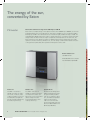
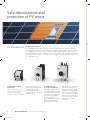
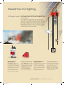
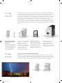
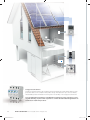
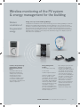
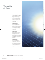
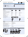
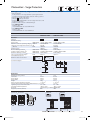
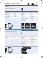
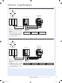
www.eaton-solar.com Catalogue 2011 Inverters and electrical systems for residential photovoltaic applications W7400-7622.indd 1 04.07.11 14:33 All about safety for solar energy Using free energy – safe for its consumers. The Sun provides 15,000 times more energy than consumed worldwide – reliably and free of charge. Modern photovoltaic installations harness this energy by using solar cells on the roof, which convert the sunlight efficiently and sustainably into electric power. The generation of renewable electricity offers great potential for the future, but means a special challenge, too. The irresistible power of the sun has to be restrained and professionally protected to prevent dangerous situations. For this reason, Eaton provides a full range of high-quality components including inverters and switchgear for residential grid-connected and grid-independent photovoltaic applications. 2 W7400-7622.indd 2 04.07.11 14:33 Eaton’s solutions Actively shape the future with safe photovoltaic systems and Eaton. Photovoltaic power plants convert sunlight directly into electrical energy. For this purpose, photovoltaic modules are used. A differentiation is made between grid-independent systems and systems coupled to the power grid. Photovoltaic systems that are coupled to the power grid feed the generated power directly into the electrical grid. There is no need for sophisticated intermediate storage. A system of this type consists of photovoltaic modules, one or more inverters and switchgear for operation, maintenance and protection in case of a fault, for example, DC string protection, DC surge protection, DC switch-disconnector, residual current device (RCD), AC surge protection and xComfort system (optional). To reach the necessary DC input voltage for the inverter, PV-modules are connected in series (as a string). To increase the power of the system, two or more strings are connected in parallel. All electrical systems need to be isolated, protected and switched to be made safe. Switchgear also need protection in the form of enclosures. Eaton provides a comprehensive range of components for all of these applications from one source. Disconnecting, switching and protecting. Inverters convert the DC current obtained from photovoltaic modules to AC current. The frequency and voltage characteristics are adapted to those of the public power grid to make solar energy useable. Reliable protection and main switches ensure a safe opera tion. Eaton offers the right solutions here: Safety grid disconnection devices, inverters from 1500 up to 4000 W for indoor solutions, as well as 4000 W & 4600 W for outdoor application. DC string protection DC fuse disconnector DC switch disconnector Ω DC surge protection PV inverter RCD RCD Metering board PV grid connection EATON CORPORATION Power inverters/DC and AC switchgear series W7400-7622.indd 3 3 04.07.11 14:33 The energy of the sun, converted by Eaton PV inverter Grid-connected inverter range from 1500 W up to 4600 W Eaton offers a complete range of monophase inverters from 1500 W up to 4600 W, to serve the individual requirements of each PV-system. This range is suitable for mono- and polycrystalline PV-arrays up to 40m². The maintenance-free inverters are highly reliable and easy to install. The embedded LCD display makes them easy to operate and service. A compact, sleek and modern design makes the Eaton inverters unique. Compared to similar products of the same size, the Eaton inverter’s power capacity is higher. The Maximum Power Point Tracking function yields optimum conversion efficiency. What’s more, a no-fan design combined with natural convection cooling assures a particularly silent operation and keeps the device clean. Further features are: Standard RS-232 Embedded ENS that complies with VDE 0126-1-1/DK5940 Indoor use Outdoor use Specifications The IP43 – ISG series is suitable for indoor use. Expo sure to rain, moisture, water or direct sunlight is not recommended (direct sunlight will increase internal temperatures, thus reducing efficiency). The IP65 – ISG series is suitable for indoor and outdoor use. Exposure to direct sunlight is also not recommended (direct sunlight increases internal temperatures, thus reducing efficiency). All inverters are designed for ambient temperatures within the specifi ed range (-20 to +55 °C). For optimum operation, an ambient temperature within the range of 0 to +40 °C is recommended. The AC grid voltage has to be between 190 and 256 V and 50 Hz (Italy 260 VAC). 4 W7400-7622.indd 4 EATON CORPORATION Power inverters/DC and AC switchgear series 04.07.11 14:33 The energy of the sun – the quality of Eaton. The total power of a photovoltaic system does not only depend on the area of installed PV-modules but also on the adjustment and slope of the modules. Also components such as the inverter greatly affect the efficiency. By using Eaton’s inverters, maximum power is ensured. 5 W7400-7622.indd 5 04.07.11 14:33 Safe disconnection and protection of PV arrays DC disconnection DC switch disconnectors Compact disconnectors for inverters customized enclosures or inverters. They are installed on 35 mm top-hat rails; their terminals facilitate the connection of all conventional conductor types. Eaton offers both enclosed and open switch-disconnectors. P-SOL open switchdisconnectors are intended for 6 W7400-7622.indd 6 The IEC 60364-7-712 standard requires the use of a switch-disconnector between the photovoltaic array and the inverter. Eaton provides enclosed and open switch-disconnectors for voltages up to 1000 V DC. They can be used to establish separate switching points as required by the standard VDI 6012, allowing for a defective inverter, for example, to be safely disconnected. All switch-disconnectors switch on two poles and are suitable for unearthed systems. All switches are certified by the TÜV. Perfectly enclosed for outdoor installation SOL switch-disconnectors in enclosures are ready to install. Connection variants for 2 and 3, or 4 strings, as well as for the most commonly available connector type, MC4 or metric cable glands, ensure problemfree integration in different system concepts. The enclosure is rated to the IP65 degree of protection and thus facilitates outdoor installation. Locking capabilities offer protection during service. A pressure equalization element prevents collection of condensation and thus any malfunctions due to flashovers. EATON CORPORATION Power inverters/DC and AC switchgear series 04.07.11 14:33 Hazard-free fire-fighting U< PV fireman’s switch A house is on fire. A fire-fighting appliance approaches. The fire fighters climb out, see a solar installation – and can do very little. The fire services can frequently do little else than rescue persons and animals and prevent neighbouring buildings from catching fire. The reason being that PV installations generate voltages up to 1000 V, which are still generated even after the power inverter is switched off. The Eaton fireman’s switch SOL30-SAFETY provides the solution, which disconnects the cable from the solar panels to the power inverters facilitating fire fighting without an electrical hazard. V 0 Small investment, large protection VDE 0100-712 stipulates a DC circuit-breaker, but not the location where it is installed: Frequently, the circuit-breaker is integrated into the inverter, so that the line between the power inverter and house connection is protected, but the modules and DC lines are still subjected to DC voltages of up to 1000 V and up to ~8A per string. Our fireman’s switch SOL30-SAFETY disconnects the cables between the solar modules and the power inverter with manageable effort at a reasonable cost. Ingeniously simple and simply ingenious The fireman’s switch is simply installed in the immediate vicinity of the PV module in the DC current line between the panel and power inverter. The PV modules are automatically switched off by Max the undervoltage release in the fireman’s switch, should the fire crew get the electrical utility company to de-energize the location of the fire or decide to locally actuate the PV-OFF switch. The SOL30SAFETY – full control instead of controlled burn out. EATON CORPORATION Power inverters/DC and AC switchgear series W7400-7622.indd 7 7 04.07.11 14:33 DC string protection String protection makes sense if the PV system has 3 or more strings and can be made with a DC fuse disconnector or a DC string circuit breaker. In addition to fuses, protection of photovoltaic strings is provided by string circuit-breakers. String protection devices protect photovoltaic modules from fault currents. They prevent reverse currents from intact modules to modules with a short circuit. The advantage of string circuit breakers, in comparison to fuses, is that they are immediately ready for use after a trip, when the cause of the trip has been remedied. Eaton offers both fuse-switch disconnectors as well as string circuit-breakers. String protective devices are not enclosed and are intended for installation in customized array junction boxes. When necessary, they can be combined with other components such as side-by-side terminals or surge protective devices. The trip currents for the string circuit breaker can be set over a wide range. Fuse disconnector with integrated short-circuit protection A version with a ”fuse blown“ indication for visualization of a blown fuse link is also available. At the same time, measurements can be made on the connected modules at the disconnection point. For service reasons, test probes are easily reachable. The fuse disconnector FCFDC10DI- SOL for cylindrical fuse-links ASFLC10-SOL of size 10 x 38 protects photovoltaic modules against short-circuit currents. DC surge protection 8 W7400-7622.indd 8 String circuit-breaker String circuit breakers PKZSOL are the fuseless alternative for the protection of photovoltaic modules against short circuits. They have a variable trip range that can be optimally adjusted to the actual short-circuit current of a string. A thermal release triggers at 1.05 … 1.3 times rated current and the magnetic release at 6 times rated current. Surge protective devices (SPD) for PV applications SPPT2PA is especially designed for photovoltaic applications and protects the system against transient overvoltages caused by indirect lightning strikes. Versions for earthed and unearthed systems are available. Thanks to spark gap technology, galvanic separation in unearthed systems is ensured! The units can be provided prewired in an enclosure, thus ready for plug & play! EATON CORPORATION Power inverters/DC and AC switchgear series 04.07.11 14:33 Safety and comfort for the building AC switchgear for buildings Miniature circuit-breakers (MCBs) and residual current devices (RCDs)) Digital residual current circuit-breakers (RCCB) Residual current breakers with overcurrent (RCBO) Miniature circuit-breakers (MCB) Distribution boards Digital technology makes it possible to achieve a new level in tripping accuracy, which helps to avoid unwanted tripping. This occurs, for example, as a result of permanent discharge currents on electrical devices or temporary disturbances during a thunderstorm. Eaton is the first company offering the digital residual current device, which significantly reduces nuisance tripping by permanently monitoring the system status to guarantee maximum systems availability. Three LEDs following the ”traffic light” principle, offer the benefit of indicating when the warning level of 30 % leakage current is reached. In this way, corrective measures can be implemented in the system, before the situation becomes more acute. This offers the end user a considerable degree of safety and comfort. The RCBO combines the advantages of a miniature circuit-breaker and a residual current device in one unit. It saves space and offers complete protection. Benefits are fire protection, protection of persons (type 30 mA) as well as fl exible and generous space for wiring. Whether it's plug-in terminals or screw connections, Eaton has the right circuit breakers for domestic as well as for industrial applications. A comprehensive range of accessories such as auxiliary switches, shunt releases, reset devices and clever busbar solutions facilitate a host of applications and automation solutions. From service distribution boards to meter cabinets, energy distribution and data network cabinets, Eaton offers a fully comprehensive product range of boards. Thus, all of your infrastructure needs can be covered for residual, commercial and industrial energy distribution applications. Eaton switchgear offers your customers maximum protection. The products of the Xpole series combine all of the function, mounting and safety benefi ts. They can be quickly and easily installed. Intelligent construction design solutions, which eliminate any mounting errors, guarantee high levels of safety during installation. The devices guarantee the end users not only protection for personnel (residual current device) but also protection of the electrical system (miniature circuit breaker). The product range is rounded off by a comprehensive range of intelligent switchgear such as remote switches, reset devices, etc. Additional features: • Contact position indicator red/green • A- and G/A-types are available • Can be sealed with leads in the ON or OFF position • Twin-purpose terminal (lift/open mouthed) above and below Surge-current protected designs prevent unwanted shutdown, selective types facilitate discriminative shutdown of the defective system section. EATON CORPORATION Power inverters/DC and AC switchgear series W7400-7622.indd 9 9 04.07.11 14:34 Surge protective devices Threats to electrical systems due to lightning and overvoltages are made safe by Eaton’s surge protective devices. The comprehensive product range offers protection up to the user. Easily fitted auxiliary switches facilitate monitoring of the functionality of the surge protective device. You can find further information regarding Eaton switchgear for disconnecting, protecting and switching of photovoltaic systems for commercial and industrial applications at www.eaton.com/moellerproducts. 10 W7400-7622.indd 10 EATON CORPORATION Power inverters/DC and AC switchgear series 04.07.11 14:34 Wireless monitoring of the PV system & energy management for the building Wireless visualization of the generated energy Energy sensor up to 16 A and Energy-Manager Comprehensive information from the xComfort Energy Sensor and Energy Manager: The Room Manager with integrated Energy-Manager Software enables the user to monitor the power generation of their photovoltaic system. By connecting the Eaton energy sensor to the inverter, the current feed to the grid can be read out. The data is transmitted wirelessly to the Room Manager with energy management function, where the user can easily and conveniently read parameters like U (voltage), I (current), P (power) and kWh (energy) on the display to get information about the output/input. Comfort, safety and energy management – wireless house automation from Eaton. Energy management benefits Automation tasks such as illumination management, shading control, monitoring and warning, as well as energy-efficient control concepts for heating, ventilation and air-conditioning are easy with Eaton products, and simple to implement. • Cost control • Consumption monitoring • Carbon footprint reduction As specifi ed by EU regulations, the actual energy consumption has to be clearly presented to the end consumer. The Eaton Energy Manager makes this possible: visualizing and controlling the energy consumption of specific electrical or gas appliances in the entire household, e.g. the washing machine, refrigerator, hot water heater, etc. By entering the price per measured unit into the system, the cost of a full bath or a washing cycle can be calculated very quickly. The history from the last 24 hours up to the last 12 months can be read out from the archive and displayed as a value or a trend. It is also possible to be immediately alerted when a user-defined limit has been exceeded. Eaton’s energy management software is a useful tool for private users to identify potential savings and to reduce their energy costs! EATON CORPORATION Power inverters/DC and AC switchgear series W7400-7622.indd 11 11 04.07.11 14:34 The safety of Eaton Safe disconnection: In case of fi re or flooding, the current grid will be shut down by the regional electricity supplier or the fire brigade. Eaton provides you with extra safety: Remote controlled switch disconnectors ensure the disconnection of the voltage producing modules from the grid. Safe maintenance: Whether the photovoltaic system has to be maintained or the panels cleaned up – Eaton’s DC switch disconnectors disconnect the panels from the system and help to avoid dangers while working on the roof. Safe protection: Even if a lightning arrester protects your home from lightning strikes, the induced overvoltages can damage the photovoltaic system. To avoid such damage, Eaton offers a solution: the DC surge protection. Safe interaction: The photovoltaic system converts solar energy into electricity. Efficiency and safety are provided by Eaton. We offer a full product range of efficient and protective components, which work together, from one source. 12 W7400-7622.indd 12 EATON CORPORATION Power inverters/DC and AC switchgear series 04.07.11 14:34 Content Inverter Selection Information Technical Data Page 14 Page 26 DC Disconnectors Selection Information Technical Data Page 15 Page 28 DC String Protectionr Selection Information Technical Data Page 17 Page 31 Surge Protection Selection Information Technical Data Page 20 Page 35 Energy Management Selection Information Technical Data Page 23 Page 41 EATON CORPORATION Power inverters/DC and AC switchgear series W7400-7622.indd 13 13 04.07.11 14:34 ± Photovoltaic - Inverter ~ PV inverter grid connected ISG • • • • • • • • Transormerless design Equipped with MC3 plugs High efficiency Fanless LCD display GFCI integrated (RCMU) Works with monitoring software ENS meets VDE 0126-1-1 AC output MC3 Type designation Article No. Units per package ISG1I-1500/1 ISG1I-2000/1 ISG1I-2800/1 ISG1I-3300/1 ISG1I-4000/1 134753 134754 134755 135522 134756 1 / 14 1 / 14 1 / 12 1 / 12 1 / 12 ISG1O-4000/1 ISG3O-4600/1 134757 134758 1 / 12 1/6 Indoor series IP43 sg00210 1500 W 2000 W 2800 W 3300 W 4000 W 1 pair 1 pair 1 pair 2 pairs 2 pairs Outdoor series IP65 sg00210 4000 W 4600 W 3 pairs 3 pairs Explanactions: MPP . . . . . . Maximum Power Point. ENS . . . . . . Two independent main monitoring units with allocated all-pole switching devices. GFCI . . . . . Ground Fault Current Interrupter. RCMU . . . . Residual Current Monitoring Unit. MC3 . . . . . . Multi Contact 3 14 EATON CORPORATION Power inverters/DC and AC switchgear series KUP0413_EAT_Katalog2010_GB.indd 14 W7400-7622.indd 14 01.06.2010 9:53:2914:34 Uhr 04.07.11 KUP04 3:29 Uhr Photovoltaic - DC Disconnection DC DC switch-disconnector DC switch-disconnector P-SOL 2-poles • Rated operational voltage 1000 VDC • Utilization category DC-21A Rated op. current Ie Type designation Article No. Units per package 20A 30A 63A P-SOL20 P-SOL30 P-SOL60 120934 120935 120936 1 1 1 wa_sg05409, wa_sg04709 Connection diagrams: PV array Unearthed system Earthed system PV inverter DC switch-disconnector DC switch-disconnector SOL 2-poles as pre-wired unit with protection class II, degree of protection IP65 • • • • • Rated operational voltage 1000 VDC Utilization category DC-21A Rated operational current Ie of 20 or 30 A Several versions – plugs MC4 or cable glands available Versions for 2, 3, and 4 strings (INPUT) available Ie INPUT OUTPUT Type designation Article No. Units per package 1xMC4 1xMC4 1xMC4 1xMC4 SOL20/2MC4 SOL20/4MC4 SOL30/2MC4 SOL30/4MC4 120915 120916 120922 120923 1 1 1 1 120919 120926 1 1 wa_sg00110 MC4 version 20A 20A 30A 30A 2xMC4 4xMC4 2xMC4 4xMC4 Version with metric cable glands 20A 30A 2xM12 2xM12 1xM16 1xM16 SOL20/2MV SOL30/2MV SOL20/2MC4 SOL30/2MC4 SOL20/2MV SOL30/2MV SOL20/4MC4 SOL30/4MC4 EATON CORPORATION Power inverters/DC and AC switchgear series KUP0413_EAT_Katalog2010_GB.indd 15 W7400-7622.indd 15 15 01.06.2010 9:53:3014:34 Uhr 04.07.11 Photovoltaic - PV Off Switch, PV fireman's switch PV Off Switch • • • • Degree of protection IP 65 Tamper-proof to ISO 13850/EN 418 Reset by pulling or turning Red enclosure upper section Description Type designation Article No. Units per package Complete with guard ring, 1 NO, 1 NC M22-SOL-PVT45PMPI11Q 150644 1 Complete with guard ring 2 NC M22-SOL-PVT45PMPI02Q 150645 1 Surface mount enclosure, black/red cover M22-SOL-IR1Q 150646 1 Guard ring, red, laser etched with SOLAR M22-SOL-XGPVQ 150647 1 Guard ring, red 1 M22-XGPVQ 150648 1 Pushbutton laser etched with SOLAR M22-SOL-PVT45P-MPIQ 150673 1 Complete 1 NO, 1 NC, can be sealed M22-SOL-PVLPL11-230Q 152627 1 PV fireman's switch SOL30-SAFETY DC switch-disconnector • • • • • • Rated operational voltage 1000V Utilization category DC-21A Rated operational current Ie 30A Remote release by undervoltage release 230V, 50Hz Feedback of the switching status by auxiliary contacts 1NO and 1NC Several versions - plugs MC3, MC4 or metric glands available Ie INPUT OUTPUT Type designation Article No. Units per package 30A 30A 30A 2xMC3 2xMC4 2xM12 1xMC3 1xMC4 1M16 SOL30-SAFETY/2MC3-U(230V50HZ) SOL30-SAFETY/2MC4-U(230V50HZ) SOL30-SAFETY/2MV-U(230V50HZ) 144121 144122 144123 SOL30-SAFETY_HPL 1 1 1 Connection diagrams: 16 W7400-7622.indd 16 EATON CORPORATION Power inverters/DC and AC switchgear series 04.07.11 14:34 Photovoltaic - DC String Protection DC DC string circuit-breaker DC string circuit-breaker PKZ-SOL 2-poles • Rated operational voltage 900 VDC • Rated current In 4, 6, 12, 20 and 30 A • For permissible string short-circuit currents Isc of 1.6 up to 22 A Ie Isc Type designation Article No. Units per package 4A 7A 12A 20A 30A 1.6-3A 2.6-5A 5-9A 9-15A 15-22A PKZ-SOL4 PKZ-SOL7 PKZ-SOL12 PKZ-SOL20 PKZ-SOL30 144069 144120 120937 120938 120939 1 1 1 1 1 wa_sg05409, wa_sg04709 Connection diagrams: PV-Strang Unearthed system Earthed system DC disconnection / PV inverter EATON CORPORATION Power inverters/DC and AC switchgear series W7400-7622.indd 17 17 04.07.11 14:35 Photovoltaic - DC String Protection C DC Fuse-disconnector (empty) FCFDC10DI-..-SOL • String protection of PV generator • The visual tripping indicator indicates the tripped fuse-link 50-400 V flashing 400-1000 V permanent light • Rated operational voltage 1000 VDC • For cylindrical fuse-links photovoltaic application • Lead-sealable Number of poles / Size Type designation Article No. Units per package Size 10x38 FCFDC10DI, rated operational current 25 A DC wa_sg00210 without visual tripping indicator 1 2 10x38 10x38 FCFDC10DI-1-SOL FCFDC10DI-2-SOL 137256 137257 12 / 108 6 / 54 137258 137259 12 / 108 6 / 54 with visual tripping indicator 1 2 10x38 10x38 FCFDC10DI-1L-SOL FCFDC10DI-2L-SOL Photovoltaic application Earthed system FCFDC10DI-1-SOL FCFDC10DI-1L-SOL Unearthed system FCFDC10DI-1-SOL 18 FCFDC10DI-2L-SOL EATON CORPORATION Power inverters/DC and AC switchgear series KUP0413_EAT_Katalog2010_GB.indd 18 W7400-7622.indd 18 01.06.2010 9:53:3714:35 Uhr 04.07.11 KUP04 3:37 Uhr Photovoltaic - DC String Protection Cylindrical fuse-links Size / Rated current / Rated voltage Type designation C Article No. Units per package Fuse-Links ASFLC10-..A-gPV-SOL Photolvoltaic application SG11008 10x38 10x38 10x38 10x38 10x38 10x38 10x38 10x38 10x38 2A 4A 6A 8A 10 A 12 A 16 A 20 A 25 A 1000 V DC 1000 V DC 1000 V DC 1000 V DC 1000 V DC 1000 V DC 1000 V DC 1000 V DC 900 V DC ASFLC10-2A-gPV-SOL ASFLC10-4A-gPV-SOL ASFLC10-6A-gPV-SOL ASFLC10-8A-gPV-SOL ASFLC10-10A-gPV-SOL ASFLC10-12A-gPV-SOL ASFLC10-16A-gPV-SOL ASFLC10-20A-gPV-SOL ASFLC10-25A-gPV-SOL 137279 137280 137281 137282 137283 137284 137285 137286 137287 10 / 500 10 / 500 10 / 500 10 / 500 10 / 500 10 / 500 10 / 500 10 / 500 10 / 500 PV-fuse-link selection: Maximum DC operating voltage of the fuse-link must be: 1.2 x Voc of string Rated current In of the fuse-link must be higher than or equal to: 1.5 x Isc Isc . . . . short circuit current of PV module Voc . . . open circuit voltage of string EATON CORPORATION Power inverters/DC and AC switchgear series KUP0413_EAT_Katalog2010_GB.indd 19 W7400-7622.indd 19 19 01.06.2010 9:53:3814:35 Uhr 04.07.11 Photovoltaic - Surge Protection DC SPD-type T2 (Class C) Max. Cont. Op. Volt. UC Type designation Article No. Units per package Plug-in surge arrester SPPT2PA for photovoltaic application For earthed systems SG11009 600 V DC 1000 V DC SPPT2PA-600-2PE SPPT2PA-1000-2PE 132663 132664 1 / 60 1 / 60 with auxiliary switch 1000 V DC SPPT2PA-1000-2PE-AX 132666 1 / 60 600 V DC 1000 V DC SPPT2PA-600-2+1PE SPPT2PA-1000-2+1PE 132661 132662 1 / 40 1 / 40 with auxiliary switch 1000 V DC SPPT2PA-1000-2+1PE-AX 132665 1 / 40 SPPT2PA-600 SPPT2PA-1000 SPPT2PA-1100 1 1 1 For unearthed systems SG11309 Inserts for replacement 600 V DC 1000 V DC 1100 V DC VOC ≤ Uc: 132667 132668 132669 Open circuit voltage of the PV generator shall be equal to or less than maximum continuous operating voltage of the Surge Protective Device (SPD) to protect it from damage. VOC . . . . . .Open circuit voltage of PV generator. UC . . . . . . .Maximum continuous operating voltage of SPD. Attention: Ensure system is de-energized before installation. Measure to ensure zero potential. Earthed system Unearthed system SPPT2PA-600-2PE SPPT2PA-1000-2PE(-AX) SPPT2PA-600-2+1PE SPPT2PA-1000-2+1PE(-AX) L- 20 L- L+ EATON CORPORATION Power inverters/DC and AC switchgear series KUP0413_EAT_Katalog2010_GB.indd 20 W7400-7622.indd 20 01.06.2010 9:53:3914:35 Uhr 04.07.11 KUP04 3:39 Uhr Photovoltaic - Surge Protection DC SPD-type T2 (Class C) PV surge protective device SOL-SP as a pre-wired unit with protection class II, degree of protection IP65 • For unearthed photovoltaic systems up to 600 VDC and 1000 VDC • Rated operational current Ie=30 ADC for versions MC3, MC4 Rated operational current Ie=32 ADC for version with metric cable glands • PE conductor has to be connected direct to the surge protection device PE terminal – metric cable gland M16 in the enclosure for PE conductor Voc wa_sg06509 INPUT OUTPUT Type designation Article No. Units per package 1xMC3 1xMC3 SOL-SP600U/2MC3 SOL-SP1000U/2MC3 144124 144127 1 1 1xMC4 1xMC4 SOL-SP600U/2MC4 SOL-SP1000U/2MC4 144125 144128 1 1 144126 144129 1 1 MC3 version 600VDC 2xMC3 1000VDC 2xMC3 MC4 version 600VDC 2xMC4 1000VDC 2xMC4 Version with metric cable glands 600VDC 2xM16 1000VDC 2xM16 VOC ≤ Uc: 1xM16 1xM16 SOL-SP600U/2MV SOL-SP1000U/2MV Open circuit voltage of the PV generator shall be equal to or less than maximum continuous operating voltage of the Surge Protective Device (SPD) to protect it from damage. VOC . . . . . .Open circuit voltage of PV generator. UC . . . . . . .Maximum continuous operating voltage of SPD. Attention: Even when switched off, the DC disconnector is under high voltage! Ensure system is de-energized before installation. Measure to ensure zero potential. Connection example: Protected area DC disconnection PE conductor has to be layed seperately to conductors of protected area PV inverter EATON CORPORATION Power inverters/DC and AC switchgear series KUP0413_EAT_Katalog2010_GB.indd 21 W7400-7622.indd 21 21 01.06.2010 9:53:4014:35 Uhr 04.07.11 Photovoltaic - Surge Protection AC SPD-type T2 (Class C) Max. Cont. Op. Volt. UC In (8/20)μs sg13309 Type designation Article No. Units per package 131755 131756 131757 131758 131759 131760 131761 131762 131773 131774 12 / 120 1 / 60 1 / 40 1 / 30 12 / 120 1 / 60 1 / 40 1 / 30 1 / 60 1 / 30 SPMT2PA-280 SPMT2PA-335 SPMT2PA-NPE 131778 131779 131783 4 / 120 4 / 120 4 / 120 Description Type designation Article No. Units per package Auxiliary switch for SPMT2PA ASAUXSC-SPM 131785 4 / 120 131784 12 / 120 Plug-in surge arrester SPMT2PA, 1- to 4-pole 1-pole 2-pole 3-pole 4-pole 1-pole 2-pole 3-pole 4-pole 1+1p 3+1p 280VAC 280VAC 280VAC 280VAC 335VAC 335VAC 335VAC 335VAC – – 1x20kA 2x20kA 3x20kA 4x20kA 1x20kA 2x20kA 3x20kA 4x20kA – – SPMT2PA-280/1 SPMT2PA-280/2 SPMT2PA-280/3 SPMT2PA-280/4 SPMT2PA-335/1 SPMT2PA-335/2 SPMT2PA-335/3 SPMT2PA-335/4 SPMT2PA-1+NPE SPMT2PA-3+NPE Inserts SPMT2PA for replacement SG13109 Insert 1-pole Insert 280VAC Insert 335VAC Insert N-PE 260VAC SG12809 20kA 20kA 30kA Lead-through terminal for SPMT2PA SG12909 ASLTT-63 22 EATON CORPORATION Power inverters/DC and AC switchgear series KUP0413_EAT_Katalog2010_GB.indd 22 W7400-7622.indd 22 01.06.2010 9:53:4014:35 Uhr 04.07.11 KUP04 3:40 Uhr Photovoltaic- RF System - Flush-mounted devices Design rf05410 Type designation Article No. Units per package Energy sensor • The "energy sensor" is used to record the solar energy converted in the PV inverter and to forward this information to the Room-Manager equipped with "Energy management function". This type of device is used for capacities of 3-3680 W. It is used to determine current (A), voltage (V), power (kW) and energy (kWh). The "energy sensor" is preferably connected at the feeding point in the electrical system. The device is mounted in the switch box, the junction box or the installation box. • Warning: The device is not calibrated and is thus not suitable for billing purposes! rf05410 0,42VA/230VAC, Measuring range 3-3680 W (max. 16A) CEMU-01/04 Design Type designation 136477 Article No. 1 Units per package Energy sensor with external sensor • The "energy sensor with external sensor" is used to record the solar energy converted in the PV inverter and to forward this information to the Room-Manager equipped with "Energy management function". This type of device is used for larger capacities of 15 W 23 kW. It is used to determine current (A), voltage (V), power (kW) and energy (kWh). The energy sensor's external sensor is connected through the supply line, preferably at the feeding point in the electrical system. The device is mounted in the switch box, the junction box or the installation box. • Warning: The device is not calibrated and is thus not suitable for billing purposes! 0.42 VA/230 VAC, CEMU-01/03 Measuring range ext. sensor 15 W - 23 kW (max. 100 A) 136476 1 EATON CORPORATION Power inverters/DC and AC switchgear series KUP0413_EAT_Katalog2010_GB.indd 23 W7400-7622.indd 23 23 01.06.2010 9:53:4014:35 Uhr 04.07.11 Photovoltaic- RF System - Surface mounted devices Design Type designation Article No. Units per package Room-Manager: white, 1 VA, 230 AC, without Bluetooth rf09410 • The "Room-Manager" is a central display and operating device. In connection with the energy sensors (with or without external sensors), the solar energy emitted by the PV inverter is displayed. In addition, the device offers thoroughly tested applications such as heating and cooling for individual rooms, ventilation, time functions, shading, safety, etc., to achieve a modern electrical installation. The "Room-Manager" communicates with all devices that are part of the Eaton RF system. The most modern touch-button sensor technology makes it possible for the user to easily operate the system on site, and to program all parameters (e.g. time settings, temperature, etc.). The back-lit graphic display guarantees a simple and concise display of the most important information for the end client. The device is to be surface-mounted on a wall. Alternatively, the device can be affixed to a 55 mm or 68 mm switch box, junction box or installation box. The integrated IR interface is used for system updates or to expand functions. The device feed is carried out through the power supply line. • Note: In order to obtain the exact measurement and display of the temperature, use the reference measuring device to determine the difference and then adjust the "Offset" in the MRF system. Room-Manager: Energy management 4 counter inputs (impulse counters or energy sensor), e.g. solar energy, electrical energy, water, gas, etc. Per input: Unit of measurement, count constant, base value, costs, CO2 emissions Per input: Graphic display of progression during diverse time periods (1 day, 7 days, 30 days, 12 months) The display is adjustable Each input allows 1 threshold value followed by an "action in case this value is exceeded"; the limit value can be adjusted Overview display of up to 3 different counter inputs Room-Manager: Comfort management 2 local buttons, freely assignable 3 rooms for 1-level heating/cooling, adjustable time-temperature program, target/actual temperature display, operating modes can be selected, integration of 3 window contacts per room 1 1-level ventilation, adjustable time program, operating modes can be selected, manual control 1 time and date display, automatic switch for daylight saving times in summer/winter 10 inputs, displays for temperature, humidity, light intensity, etc. 10 outputs, display and operation of electrical consumers 1 outdoor temperature, max./min/trend display, re-setting of the trend display 3 timers, adjustable time program, operating modes can be selected, manual control 3 shading units with time program and manual control, time program is adjustable 1 holiday function, time and date are adjustable 1 presence simulator, settings adjustable for a max. of 10 consumers, time and activation function 3 logic operations with 2 inputs each, AND/OR connection 2 scenes with 6 functions each, function is adjustable 1 request for total heating 1 request for total cooling Battery status display and advance warning for all battery-operated devices that are assigned to the Room-Manager Software update conducted via IRDA Adjustable password protection Multi-language menu (depending upon article number) General settings Room-Manager: Safety management (additional function) This fee-based function can be activated at www.moeller.at 2 separate areas can be monitored (e.g. indoors, outdoors, upper floor, etc.) 2 areas can be activated/deactivated individually or together 3 inputs to activate/deactivate, alternatively 4-digit codes can be used 10 additional inputs for safety (motion detectors, window contacts, sensors, etc.) 2 outputs for "Safety" alert purposes (sirens, flashing lights) 5 additional inputs for smoke detectors, regardless of whether Safety function is activated/deactivated 1 output for "Smoke detector" alert (sirens, flashing lights) Adjustable time delay for activation/deactivation upon entering/leaving a room Attention: This is a warning function, not a smoke/fire alarm or other alarm system!!! GB,NO,SE,FI GB,NL,FR,DE,IT GB,RO,HU,PL,TR GB,DE,CZ,GR 24 CRMA-00/03 CRMA-00/04 CRMA-00/05 CRMA-00/06 118783 118784 118785 118786 1 1 1 1 EATON CORPORATION Power inverters/DC and AC switchgear series KUP0413_EAT_Katalog2010_GB.indd 24 W7400-7622.indd 24 01.06.2010 9:53:4114:35 Uhr 04.07.11 KUP04 3:41 Uhr Photovoltaic- Energy Management Design RF01506 Type designation Article No. Units per package USB-RS232 adapter cable • The "USB-RS232 adapter cable" is used to connect the PV inverter (with RS232 interface) to the laptop/notebook/PC (with USB port). In this manner, all data from the PV inverter can be evaluated by the "Watch-SOL Software". CRSZ-00/03 Design RF03107 Type designation 104932 Article No. 1 Units per package DIN-rail-clip • The energy sensor (with or without external sensor) can be attached to the "DIN-rail-clip" in order to snap this combination onto any possible DIN-rail. Note: Do not use metal distribution boards under any circumstances since metal can block the radio signal!!! Info: The price and the order number refer to one "DIN-rail-clip" unit. We cannot deliver single units! Therefore, please order at least one package (10 units) or a multiple thereof. CMMZ-00/30 135529 10 EATON CORPORATION Power inverters/DC and AC switchgear series KUP0413_EAT_Katalog2010_GB.indd 25 W7400-7622.indd 25 25 01.06.2010 9:53:4114:35 Uhr 04.07.11 ± Photovoltaic - Inverter ~ PV inverter grid connected indoors ISG1I • Field of application: For use with mono- and polycrystalline PV modules to build up a photovoltaic system • Transformerless design • High efficiency • Fanless design keeps the device clean • ENS acc. to VDE 0126-1-1 integrated • RCMU acc. to VDE 0126-1-1 integrated • Application acc. to IEC 60364-7-712 and IEC 62548*) Connection diagram ISG1I..../1 Technical Data ISG1I-1500/1 Electrical DC Max. DC power ± Max. DC voltage ~ MPP voltage range Nominal DC voltage Max. input current MPP Tracker AC Output power ± Max. output power ~ Operating voltage Operating frequency Current THD Power factor Power connection SYSTEM Max. efficiency ± Euro efficiency ~ Stand-by power Overvoltage category Degree of protection Operating temperature Humidity (non-condensing) Accustic noise level Comm. interface Display Mechanical W x H x D [mm] T1 [mm] Weight [kg] ISG1I-2000/1 ISG1I-2800/1 ISG1I-3300/1 ISG1I-4000/1 1760 W 2320 W 450 VDC 500 VDC 150-405 VDC 150-450 VDC 360 VDC 400 VDC 8.9 ADC 10 ADC 1 1 1500 W 2000 W 1650 W 2200 W 190-256 VAC 190-256 VAC 50 Hz 50 Hz ~ 3% ~ 3% <1 <1 1-phase 1-phase > 95% > 96% > 94% > 95% ≤ 7W ≤ 7W III III IP43 IP43 -20°C to +55°C -20°C to +55°C 0-95% 0-95% < 35 dBA < 35 dBA RS232 (RS485 optional) LCD / 1 line, 16 characters 3180 W 500 VDC 150-450 VDC 400 VDC 13 ADC 1 2800 W 3000 W 190-256 VAC 50 Hz ~ 3% <1 1-phase > 96% > 95% ≤ 7W III IP43 -20°C to +55°C 0-95% < 35 dBA 3820 W 500 VDC 150-450 VDC 400 VDC 17 ADC 1 3300 W 3600 W 190-256 VAC 50 Hz ~ 3% <1 1-phase > 96% > 95% ≤ 7W III IP43 -20°C to +55°C 0-95% < 35 dBA 4630 W 500 VDC 150-450 VDC 400 VDC 20 ADC 1 4000 W 4400 W 190-256 VAC 50 Hz ~ 3% <1 1-phase > 96% > 95% ≤ 7W III IP43 -20°C to +55°C 0-95% < 35 dBA 326x270x130 340 9.2 360x303x145 373 12.5 447x389x146 459 16.4 447x389x146 459 16.4 360x303x130 373 11.5 Dimensions (mm) Explanation: THD . . . . . . Total Harmonic Distortion *) in preparation 26 EATON CORPORATION Power inverters/DC and AC switchgear series KUP0413_EAT_Katalog2010_GB.indd 26 W7400-7622.indd 26 01.06.2010 9:53:4114:35 Uhr 04.07.11 KUP04 3:41 Uhr ± Photovoltaic - Inverter ~ PV inverter grid connected outdoors ISG.O • Field of application: For use with mono- and polycrystalline PV modules to build up a photovoltaic system • Transformerless design • High efficiency • Fanless design keeps the device clean • ENS acc. to VDE 0126-1-1 integrated • RCMU acc. to VDE 0126-1-1 integrated • Application acc. to IEC 60364-7-712 and IEC 62548*) Connection diagrams ISG1O..../1 ISG3O..../1 Technical Data ISG1O-4000/1 ISG3O-4600/1 Electrical DC Max. DC power ± Max. DC voltage ~ MPP voltage range Nominal DC voltage Max. input current MPP Tracker AC Output power ± Max. output power ~ Operating voltage Operating frequency Current THD Power factor Power connection SYSTEM Max. efficiency ± Euro efficiency ~ Stand-by power Overvoltage category Degree of protection Operating temperature Humidity (non-condensing) Accustic noise level Comm. interface Display 4630 W 500 VDC 150-450 VDC 400 VDC 20 ADC 1 4000 W 4400 W 190-256 VAC 50 Hz ~ 3% <1 1-phase > 96% > 95% ≤ 7W III IP65 -20°C to +55°C 0-95% < 35 dBA RS232 (RS485 optional) LCD / 1 line, 16 characters 3800 W per tracker 750 VDC 125-700 VDC 600 VDC 8.5 ADC per tracker 3 4600 W 5000 W 190-256 VAC 50 Hz ~ 3% <1 1-phase > 96% > 94.5% ≤ 8W III IP65 -20°C to +55°C 0-95% < 35 dBA RS232 (RS485 optional) LCD / 2 lines, 32 characters Mechanical W x H x D [mm] T1 [mm] Weight [kg] 447x389x146 459 19.5 442x532x134 602 27 Dimensions (mm) Explanation: THD . . . . . . Total Harmonic Distortion *) in preparation EATON CORPORATION Power inverters/DC and AC switchgear series KUP0413_EAT_Katalog2010_GB.indd 27 W7400-7622.indd 27 27 01.06.2010 9:53:4214:35 Uhr 04.07.11 Photovoltaic - DC Disconnection DC DC Switch-disconnector P-SOL • Field of application: DC disconnection in photovoltaic systems between PV array and inverter to switch off the energy • No polarity • Any mounting position • Spring work contacts • Tested according to IEC/EN 60947-3, UL508 • Certificate TÜV-Rheinland Connection diagram Unearthed system Earthed system Technical Data P-SOL20 P-SOL30 P-SOL60 2 1000 VDC 20 A 500 A 700 A DC-21 A III 8 kV 1500 6 mΩ 2 1000 VDC 30 A 500 A 700 A DC-21 A III 8 kV 1500 5 mΩ 2 1000 VDC 63 A 1500 A 1500 A DC-21 A III 8 kV 1500 3 mΩ 58 93 76 265 g 35 mm 58 93 76 265 g 35 mm IP20 2x (1-6) 18-10 1.7 Nm -25°C to +60°C Damp heat, constant Damp heat, cyclic 2 100,000 <120 IP20 2x (1-6) 18-10 1.7 Nm -25°C to +60°C 55 140 160 920 g 35 mm 2xM4x18 IP20 2x (1-35) 14-2 3 Nm -25°C to +60°C 2 100,000 <120 2 100,000 <120 Electrical Number of poles Rated operational voltage Ue Rated operational current Ie Rated short-circuit making capacity Icm Rated short-time withstand current 1sec. Icw Utilization category Overvoltage category Rated impulse withstand voltage Uimp Operating cycles electrical at Ue and Ie Internal resistance Mechanical Width Height Depth Weight Mounting quick fastening on DIN rail acc. to IEC/EN 60517 Screw fastening Degree of protection Terminal capacity Flexible with end sleeve mm² AWG Tightening torque of terminal screws Ambient temperature range Climatic resistance acc. to IEC 60068-2-78 acc. to IEC 60068-2-30 Pollution degree Operating cycles mechanical Operating cycles mechanical per hour Dimensions (mm) P-SOL20 P-SOL30 28 P-SOL60 EATON CORPORATION Power inverters/DC and AC switchgear series KUP0413_EAT_Katalog2010_GB.indd 28 W7400-7622.indd 28 01.06.2010 9:53:4214:35 Uhr 04.07.11 KUP04 3:42 Uhr Photovoltaic - DC Disconnection DC DC Switch-disconnector SOL30-Safety • Field of application: : DC disconnection in photovoltaic systems between PV array and inverter to switch off the energy • Remote release by undervoltage release 230V, 50Hz • Feedback of the switching status by auxiliary contacts 1 NO and 1 NC • Pre-wired unit ready for connection • Lock-able in OFF-position with a padlock • Any mounting position • Spring work contacts • Application acc. to IEC/EN 60947-3 Technical Data SOL30-SAFETY Electrical Number of poles Rated operational voltage Ue Rated operational current Ie Rated short-circuit making capacity Icm Rated short-time withstand current 1sec. Icw Utilization category Overvoltage category Rated impulse withstand voltage Uimp Operating cycles electrical at Ue and Ie Internal resistance 2 1000 VDC 30 A 500 A 700 A DC-21 A III 8 kV 1500 5 mΩ Mechanical Weight Degree of protection Ambient temperature range Climatic resistance acc. to 60068-2-78 acc. to 60068-2-30 Pollution degree Operating cycles mechanical Operating cycles mechanical per hour 470 g IP65 -25°C to +60°C Damp heat, constant Damp heat, cyclic 3 100,000 <120 Dimensions (mm) SOL30Safety a [mm] MC3 197 MC4 234 MV 224 EATON CORPORATION Power inverters/DC and AC switchgear series KUP0413_EAT_Katalog2010_GB.indd 29 W7400-7622.indd 29 29 01.06.2010 9:53:4614:35 Uhr 04.07.11 Photovoltaic - DC Disconnection DC DC Switch-disconnector SOL as pre-wired unit • Field of application: DC disconnection in photovoltaic systems between PV array and inverter to switch off the energy • Pre-wired unit ready for connection • Lock-able in OFF-position with a padlock • Any mounting position • Spring work contacts • Tested according to IEC/EN 60947-3, UL508 • Certificate TÜV-Rheinland Connection diagram Unearthed system Earthed system Technical Data SOL20 SOL30 2 1000 VDC 20 A 500 A 700 A DC-21 A III 8 kV 1500 8 mΩ 2 1000 VDC 30 A 500 A 700 A DC-21 A III 8 kV 1500 7 mΩ 420 g IP65 420 g IP65 -25°C to +60°C Damp heat, constant Damp heat, cyclic 3 100,000 <120 -25°C to +60°C Electrical Number of poles Rated operational voltage Ue Rated operational current Ie Rated short-circuit making capacity Icm Rated short-time withstand current 1sec. Icw Utilization category Overvoltage category Rated impulse withstand voltage Uimp Operating cycles electrical at Ue and Ie Internal resistance Mechanical Weight Degree of protection Terminal capacity with / without end sleeve AWG Ambient temperature range Climatic resistance acc. to 60068-2-78 acc. to 60068-2-30 Pollution degree Operating cycles mechanical Operating cycles mechanical per hour mm² 3 100,000 <120 Dimensions (mm) SOL20(30) a [mm] MC4 234 MV 224 SOL20 SOL30 SOL20/2MC4 SOL30/2MC4 Input + Strings - Strings SOL20/2MV SOL30/2MV Input (M12) + Strings - Strings 1 3 5 1 3 5 2 4 6 2 4 6 + SOL20/4MC4 SOL30/4MC4 Input + Strings - Strings 1 3 5 2 4 6 Output (M16) - + Output 30 EATON CORPORATION Power inverters/DC and AC switchgear series KUP0413_EAT_Katalog2010_GB.indd 30 W7400-7622.indd 30 01.06.2010 9:53:4914:35 Uhr 04.07.11 KUP04 3:49 Uhr Photovoltaic - DC String Protection DC DC string circuit-breaker PKZ-SOL • Field of application: DC circuit-breaker for string protection in photovoltaic systems • No polarity • Spring work contacts • Tested according to IEC/EN 60947-2 • Certificate TÜV-Rheinland Connection diagram Unearthed system Earthed system Technical Data PKZ-SOL4 PKZ-SOL7 PKZ-SOL12 PKZ-SOL20 PKZ-SOL30 Electrical Number of poles Rated operational voltage Ue Rated current In Thermal tripping characteristic Electromagnetc tripping characteristic Rated ultimate short-circuit breaking capacity Icu Rated service short-circuit breaking capacity Ics Overvoltage category Rated impulse withstand voltage Uimp Operating cycles electrical at Ue and In Internal resistance 2 900 VDC 4 / 7 / 12 / 20 / 30 A 1.05 to 1.3 x In 6 x In 5 kA 1.5 kA III 8 kV 1500 138 / 60 / 32 / 14 / 9 m Ω Mechanical Width Height Depth Weight Mounting quick fastening on DIN rail acc. to IEC/EN 60517 Screw fastening Degree of protection Terminal capacity Flexible with end sleeve mm² AWG Tightening torque of terminal screws Ambient temperature range Climatic resistance acc. to IEC 60068-2-78 acc. to IEC 60068-2-30 Pollution degree Operating cycles mechanical Operating cycles mechanical per hour 58 93 76 265 g 35 mm IP20 2x (1-6) 18-10 1.7 Nm -25°C to +60°C Damp heat, constant Damp heat, cyclic 2 100,000 <120 Mounting position PKZ-SOL4 PKZ-SOL7 PKZ-SOL12 PKZ-SOL20 PKZ-SOL30 90° 90° 90° EATON CORPORATION Power inverters/DC and AC switchgear series KUP0413_EAT_Katalog2010_GB.indd 31 W7400-7622.indd 31 31 01.06.2010 9:53:5114:35 Uhr 04.07.11 Photovoltaic - DC String Protection DC DC string circuit-breaker PKZ-SOL Characteristic curve setting value - short-circuit-current According to the design for IEC 62548-1, the tripping current for the circuit-breaker must fall within a range of 1.4 to 2 times the value of the short-circuit current of the PV modules, in order to protect the PV modules. Since only the current values for the built-in overload tripping device can be plotted on the setting scale of the circuit breaker1), the correlation between the tripping current for the safety device and the short-circuit current for the PV modules must be properly indicated for every point of the scale. Tripping characteristic curve String circuit breaker PKZ-SOL Adjustment tool for the String Circuit-Breaker PKZ-SOL tripping time 35 Setting value on the Circuit-Breaker [A] 30 PKZ-SOL30 25 20 PKZ-SOL20 15 PKZ-SOL12 10 PKZ-SOL7 5 PKZ-SOL4 0 0 5 10 15 20 25 Short circuit current of the Solar module [A] 1) Norm IEC/EN 60947-2 (section 4.7.3) prohibits a direct specification of the PV short-circuit current on the circuit-breaker's setting scale, whereby only the setting value for the response current may be entered. Dimensions (mm) PKZ-SOL4 PKZ-SOL7 PKZ-SOL12 PKZ-SOL20 PKZ-SOL30 32 EATON CORPORATION Power inverters/DC and AC switchgear series KUP0413_EAT_Katalog2010_GB.indd 32 W7400-7622.indd 32 01.06.2010 9:53:5314:35 Uhr 04.07.11 KUP04 3:53 Uhr Photovoltaic - DC String Protection DC C Fuse-disconnector FCFDC10DI-..-SOL • Design according to IEC 60947-1 Ed. 4.0, EN 60947-1:1999+A1:2000+A2:2001 IEC 60947-3 Ed. 2.1, EN 60947-3:1999+A1:2001 • Types L with visual tripping indicator • Suitable for cylindrical fuse-links photovoltaic application 10x38 according to IEC 60269, UL284-4 • Can be sealed with lead • Supplied without fuse-links Technical Data Electrical Number of poles Rated voltage Ue Rated current Ie Rated conditional short-circuit current Utilization category Rated insulation voltage Ui Overvoltage category Rated impulse withstand voltage Uimp Power loss per current path without fuse-link Maximum permissible power loss of fuse-links 1P, 2P 1000 V DC 25 A 10 kA DC 20 B 1000 V DC III 6 kV Mechanical Frame size Device height Device width Weight 1P 2P Mounting Degree of protection Terminals above and below Terminal capacity 0.9 W 3W Tightening torque of terminal screws Ambient temperature range Flame class Pollution degree Comparative tracking index 45 mm 83.3 mm 17.5 mm per pole 58 g 70 g Quick fastening on DIN rail IEC/EN 60715 IP20 lift terminals 0.5 - 10 mm2 AWG 20-8 1.2 Nm -25 to +40°C glow wire tested 960°C 2 CTI 450 Dimensions (mm) 17,5 EATON CORPORATION Power inverters/DC and AC switchgear series KUP0413_EAT_Katalog2010_GB.indd 33 W7400-7622.indd 33 33 01.06.2010 9:53:5514:35 Uhr 04.07.11 Photovoltaic - DC String Protection Cylindrical fuse-links C Fuse-Links ASFLC10-..A-gPV-SOL photovoltaic application • According to IEC 60269-1 and IEC 60269-4 • For fuse-switch-disconnectors FCFDC10DI Connection diagram Technical Data Electrical ASFLC10-..A-gPV-SOL 10x38 6 - 20 A / 1000 V DC 25 A / 900 V DC – 30 kA 2 ms Rated voltage Un Rated frequency Rated short-circuit breaking capacity τ = L/R Max.Power dissipation Rated current Pre-arcing Joule integral In L/R = 2 ms [A] 2 4 6 8 10 12 16 20 25 [A2s] 1.3 3.3 5.5 8 11 23 35 50 75 Dimensions (mm) Type Size ASFLC10 10x38 a 38.0±0.6 Operating Joule integral L/R = 2 ms Power dissipation at 0.7 x In [A2s] 3.5 28 45 62 88 180 270 430 620 [W] 1.47 0.52 0.73 0.93 1.06 1.03 1.00 1.18 1.25 bmax. 10.5 c 10.3±0.1 dmin. 6 Power dissipation at In Pd [W] 1.00 1.25 1.65 1.9 2.3 1.9 2.5 3.25 3.45 Weight Pd [g] 10 10 10 10 10 10 10 10 10 r 1.5±0.5 Characteristics ASFLC10-..A-gPV-SOL, photolvoltaic application Operating time t in s Time/current characteristics of ASFLC10-..A-gPV-SOL Fuse-links 2 ... 25A Instantaneous current Ip in A 34 EATON CORPORATION Power inverters/DC and AC switchgear series KUP0413_EAT_Katalog2010_GB.indd 34 W7400-7622.indd 34 01.06.2010 9:53:5714:35 Uhr 04.07.11 KUP04 3:57 Uhr Photovoltaic - Surge Protection DC SPD-type T2 (Class C), plug-in surge arresters SPPT2PA-...-2PE • Field of application: Connection For the protection of photovoltaic systems against transient overvoltage SPPT2PA-...-2PE caused by indirect lightning strike and switching operations. • Test class II according to IEC 61643-1 • SPD-type T2 according to EN 61643-11 • Types SPPT2PA-...-AX for remote message transmission of defective inserts diagrams Technical Data Electrical Response time Maximum continuous operating voltage UC Rated frequency Nominal discharge current In Voltage protection level Up Residual voltage at 5 kA (8/20) μs Maximum discharge current Imax Permissible back-up fuse Maximum short-circuit current Isc Residual current IPE Mechanical Frame size Device height Device width Weight Upper and lower lift terminal capacity stranded / solid core Tightening torque of terminal screws Permitted ambient temperature Mounting Degree of protection Polution degree SPPT2PA-600-2PE SPPT2PA-1000-2PE(-AX) ≤ 25 ns 600 V DC DC 15 kA (8/20) μs ≤ 3 kV ≤ 2.5 kV 30 kA (8/20) μs – 80 A ≤ 20 μA ≤ 25 ns 1000 V DC DC 15 kA (8/20) μs ≤ 5 kV ≤ 4 kV 30 kA (8/20) μs – 80 A ≤ 20 μA 45 mm 90 mm 35.6 mm 247 g 45 mm 90 mm (99 mm) 35.6 mm 247 g (249 g) 4-25/4-35 mm2/AWG11-2 4-25/4-35 mm2/AWG11-2 4.5 Nm 4.5 Nm -40°C up to +80°C -40°C up to +80°C quick fastening on DIN rail IEC/EN 60715 IP20 IP20 2 2 Auxiliary switch Electrical Rated insulation voltage Rated frequency Switching contact Minimum voltage per contact Rated operational current Min. admissible power Dimensions (mm) 250 V 50/60 Hz 1 CO 5 V AC/DC 1.5 A / 250 V AC 1.5 A / 30 V DC 5 mA / 5 V Mechanical Terminal capacity stranded / solid core Tightening torque of terminal screws 1.5/1.5 mm2/AWG28-16 0.25 Nm Application hints according to EN 50539-12 EATON CORPORATION Power inverters/DC and AC switchgear series KUP0413_EAT_Katalog2010_GB.indd 35 W7400-7622.indd 35 35 01.06.2010 9:53:5714:35 Uhr 04.07.11 Photovoltaic - Surge Protection DC SPD-type T2 (Class C), plug-in surge arresters SPPT2PA-...-2+1PE • Field of application: Connection For the protection of photovoltaic systems against transient overvoltage SPPT2PA-...-2+1PE caused by indirect lightning strike and switching operations. • Test class II according to IEC 61643-1 • SPD-type T2 according to EN 61643-11 • Galvanic isolation in unearthed systems by means of a spark gap • Types SPPT2PA-...-AX for remote message transmission of defective inserts diagrams Technical Data Electrical Response time Maximum continuous operating voltage UC Rated frequency Nominal discharge current In Voltage protection level Up Residual voltage at 5 kA (8/20) μs Maximum discharge current Imax Permissible back-up fuse Maximum short-circuit current Isc Residual current IPE L+ -> L- / L -> PE L+ -> L- / L -> PE L+ -> L- / L -> PE Mechanical Frame size Device height Device width Weight Upper and lower lift terminal capacity stranded / solid core Tightening torque of terminal screws Permitted ambient temperature Mounting Degree of protection Polution degree SPPT2PA-600-2+1PE SPPT2PA-1000-2+1PE(-AX) ≤ 25 ns / ≤ 100 ns 600 V DC DC 15 kA (8/20) μs ≤ 3 kV / ≤ 3 kV ≤ 2.5 kV / ≤ 2 kV 30 kA (8/20) μs – 80 A ≤ 20 μA ≤ 25 ns / ≤ 100 ns 1000 V DC DC 15 kA (8/20) μs ≤ 5 kV / ≤ 3 kV ≤ 4 kV / ≤ 2 kV 30 kA (8/20) μs – 80 A ≤ 20 μA 45 mm 90 mm 53.4 mm 318 g 45 mm 90 mm (99 mm) 53.4 mm 318 g (323 g) 4-25/4-35 mm2/AWG11-2 4-25/4-35 mm2/AWG11-2 4.5 Nm 4.5 Nm -40°C up to +80°C -40°C up to +80°C quick fastening on DIN rail IEC/EN 60715 IP20 IP20 2 2 Auxiliary switch Electrical Rated insulation voltage Rated frequency Switching contact Minimum voltage per contact Rated operational current Min. admissible power Dimensions (mm) 36 250 V 50/60 Hz 1 CO 5 V AC/DC 1.5 A / 250 V AC 1.5 A / 30 V DC 5 mA / 5 V Mechanical Terminal capacity stranded / solid core Tightening torque of terminal screws 1.5/1.5 mm2/AWG28-16 0.25 Nm Application hints according to EN 50539-12 EATON CORPORATION Power inverters/DC and AC switchgear series KUP0413_EAT_Katalog2010_GB.indd 36 W7400-7622.indd 36 01.06.2010 9:53:5814:35 Uhr 04.07.11 KUP04 3:58 Uhr Photovoltaic - Surge Protection DC SPD-Type T2 (Class C), PV surge protection device SOL-SP as a pre-wired unit Connection diagram INPUT u OUTPUT M16 • Field of application: For the protection of photovoltaic systems against transient overvoltage caused by indirect lightning strike and switching operations. • Test class II according to IEC 61643-1 • SPD-type T2 according to EN 61643-11 • Galvanic isolation in unearthed systems by means of a spark gap Technical Data SOL-SP600 SOL-SP1000 ≤ 25 ns / ≤ 100 ns 600 V DC DC 15 kA (8/20) μs ≤ 3 kV / ≤ 3 kV ≤ 2.5 kV / ≤ 2 kV 30 kA (8/20) μs – 80 A ≤ 20 μA 600 VDC 30 A 32 A ≤ 25 ns / ≤ 100 ns 1000 V DC DC 15 kA (8/20) μs ≤ 5 kV / ≤ 3 kV ≤ 4 kV / ≤ 2 kV 30 kA (8/20) μs – 80 A ≤ 20 μA 1000 VDC 30 A 32 A Electrical Responding time Maximum continuous operating voltage UC Rated frequency Nominal discharge current In Voltage protection level Up Residual voltage at 5 kA (8/20) μs Maximum discharge current Imax Permissible back-up fuse Maximum short-circuit current Isc Residual current IPE Rated operational voltage Ue Rated operational current Ie Mechanical Weight Degree of protection Terminal capacity Tightening torque of terminal screws Permitted ambient temperature Pollution degree Dimensions (mm) SOL-SP L+ -> L- / L -> PE L+ -> L- / L -> PE L+ -> L- / L -> PE MC3, MC4 M16 420 g IP65 +,- without end sleeve 6 mm² AWG 10 PE stranded / flexible 4-25 / 4-35 mm² AWG 11-2 +,PE -40°C to +60°C 3 420 g IP65 6 mm² 10 4-25 / 4-35 mm² 11-2 3 Nm 3 Nm 4.5 Nm 4.5 Nm -40°C to +60°C 3 Connection example a [mm] MC3 197 MC4 234 MV 224 SOL-SP INPUT OUTPUT M16 u EATON CORPORATION Power inverters/DC and AC switchgear series KUP0413_EAT_Katalog2010_GB.indd 37 W7400-7622.indd 37 37 01.06.2010 9:53:5814:35 Uhr 04.07.11 Photovoltaic - Surge Protection AC SPD-Type T2 (Class C), plug-in surge arresters SPMT2PA • Field of application: For the protection of photovoltaic systems against transient overvoltage caused by indirect lightning strike and switching operations. • Test class II according to IEC 61643-1 • SPD-type T2 according to EN 61643-11 • Types SPPT2PA-...-AX for remote message transmission of defective inserts • Busbar connection to EATON switchgears Connection diagram Technical Data Inserts SPMT2PA -280 -335 -NPE T2 T2 Electrical SPD-type Mechanical coding Responding time Voltage protection level at nominal discharge current / Uoc Voltage protection level at 5 kA (8/20) μs Maximum continuous operating voltage Uc Temporary overvoltage test value UT Rated frequency Open circuit voltage Uoc Nominal discharge current (8/20) μs In Charge Q at In Specific energy at In Maximum discharge current Imax Follow current interrupt rating Ifi Permissible back-up fuse Maximum short-circuit current T2 T3 x < 25 ns < 1.4 kV 1000 V 280 VAC 350 VAC (5s) 50/60 Hz 10 kV 20 kA 0.57 As 5.7 kJ/Ω 40 kA – T3 x < 25 ns < 1.6 kV 1200 V 335 VAC 415 VAC (5s) 50/60 Hz 10 kV 20 kA 0.57 As 5.7 kJ/Ω 40 kA ≤ 160 AgL 50 kAr.m.s. T3 y < 100 ns < 1.5 kV 260 VAC 12000 VAC (200ms) 50/60 Hz 5 kV 40 kA 1.14 As 22.8 kJ/Ω 60 kA – mMCT-C100 20 kAr.m.s. Connection diagram Mechanical Frame size Device height Device width Weight base 1P, 1+1P, 2P, 3P, 3+1P, 4P Weight complete devices 1P, 1+1P, 2P, 3P, 3+1P, 4P Permitted ambient temperature Degree of protection (built-in) Upper and lower lift terminal capacity Upper and lower open mouthed terminals for busbar thickness up to Tightening torque of terminal screws Quick fastening on DIN rail according to Dimensions (mm) 1.5 mm 2.4 - 3 Nm IEC/EN 60715 Application Examples SPMT2PA according to IEC 60364-5-53 Clause 534 SPMT2PA280/3 38 45 mm 80 mm 17.5 mm per pole 53/120/120/180/240/240 g 110/201/220/330/412/440 g -40°C to +70°C IP40 4 - 25 mm2 SPMT2PA-280/4 SPMT2PA-3+NPE SPMT2PA1+NPE ASLT T-63 EATON CORPORATION Power inverters/DC and AC switchgear series KUP0413_EAT_Katalog2010_GB.indd 38 W7400-7622.indd 38 01.06.2010 9:53:5914:35 Uhr 04.07.11 KUP04 3:59 Uhr Photovoltaic - Surge Protection AC SPD-type 2 (Class C), surge arresters SPMT2PA-1+NPE, SPMT2PA-3+NPE • Field of application: For the protection of low voltage distribution systems against transient overvoltage caused by indirect lightning strike and switching operations. • Test class II according to IEC 61643-1 • SPD-type T2 according to EN 61643-11 • Auxiliary switch ASAUXSC-SPM for remote message transmission can be mounted onto the device • Suitable for busbar connection to EATON switchgear • Type SPMT2PA-3+NPE: consists of 1 base, 1 insert SPMT2PA-NPE and 3 inserts SPMT2PA-335 • Type SPMT2PA-1+NPE: consists of 1 base, 1 insert SPMT2PA-NPE and 1 insert SPMT2PA-335 Technical Data SPMT2PA-1+NPE SPMT2PA-3+NPE Electrical SPD-type Mechanical coding Response time Maximum continuous operating voltage UC Temporary overvoltage test value UT (5 s) (200 ms) Rated frequency Nominal discharge current In Voltage protection level Up at In Maximum discharge current Imax Follow current interrupt rating Ifi Permissible back-up fuse Maximum short-circuit current T2 L-N/N-PE/L-PE L-N/N-PE L-N N-PE L-N/N-PE/L-PE L-N/N-PE/L-PE L-N/N-PE/L-PE N-PE T3 T2 yx < 25ns/< 100ns/< 100ns 335VAC/260VAC 415 VAC 1200 VAC 50/60 Hz 20 kA (8/20)μs ≤1600V/≤1500V/≤2050V 40 kA (8/20)μs 100 Ar.m.s. ≤ 160 AgL 50 kAr.m.s. T3 yxxx < 25ns/< 100ns/< 100ns 335VAC/260VAC 415 VAC 1200 VAC 50/60 Hz 20 kA (8/20)μs ≤1600V/≤1500V/≤1900V 40 kA (8/20)μs 100 Ar.m.s. mMCT-C100 20 kAr.m.s. Connection diagram L1 x x L2 x L3 x N y Mechanical Mechanical coding of base Frame size Device height Device width Weight Upper and lower lift terminal capacity Open-mouthed terminals at both sides for busbar thickness up to Tightening torque of terminal screws Permitted ambient temperature Mounting Degree of protection (built-in) y yx yxxx 45 mm 45 mm 80 mm 80 mm 35 mm 70 mm 201 g 412 g 1 - 25 mm2 1 - 25 mm2 1.5 mm 1.5 mm 2.4 - 3 Nm 2.4 - 3 Nm -40°C to +70°C -40°C to +70°C quick fastening on DIN rail IEC/EN 60715 IP40 IP40 Dimensions (mm) Application Examples SPMT2PA-1+NPE SPMT2PA-1+NPE SPMT2PA-3+NPE N SPMT2PA-3+NPE SPMT2PA-NPE SPMT2PA-NPE SPMT2PA-335 SPMT2PA-335 EATON CORPORATION Power inverters/DC and AC switchgear series KUP0413_EAT_Katalog2010_GB.indd 39 W7400-7622.indd 39 39 01.06.2010 9:54:0014:35 Uhr 04.07.11 Photovoltaic - Surge Protection AC Auxiliary Switch for surge arresters ASAUXSC-SPM • Field of application: For mounting onto surge protective devices for external defect message transmission • Design basically in accordance with IEC 60947-5-1 • Can be mounted subsequently • Suitable for SPMT2PA Connection diagram Technical Data Electrical Rated insulation voltage Rated frequency Switching contact Minimum voltage per contact Rated operational current AC12 Maximum back-up fuse Overvoltage category Pollution degree 250 V 50/60 Hz 1 CO 24 VAC 2A/250VAC 2 A gL IV 2 Dimensions (mm) Mechanical Frame size Device height Device width Weight Mounting Degree of protection, built-in Finger and hand touch safe acc. to Upper and lower terminals Terminal capacity Tightening torque of terminal screws 45 mm 80 mm 8.8 mm 41 g screw-mounting onto SPMT2PA IP40 BGV A3, ÖVE-EN 6 lift terminals 2 x 2.5 mm2 0.8 - 1 Nm Application examples SPMT2PA-1+NPE SPMT2PA SPMT2PA Lead-through terminal for surge protective devices, SPD-type 2 (Class C), ASLTT-63 • The lead-through terminal permits orderly wiring of SPDs types 2 (class C). It serves as lead-through terminal in circuits requiring vertical connections from the upper to the lower SPD connection level. • 1-pole • Suitable for standard busbar connection to EATON switchgear Connection diagram Technical Data Electrical Rated voltage Rated current Rated frequency 690V AC/DC 63 A 50/60 Hz Mechanical Frame size Device height Device width Mounting Degree of protection, built-in Finger and hand touch safe acc. to Upper and lower terminals Terminal capacity Busbar thickness Tightening torque of terminal screws Dimensions (mm) 2.4 - 3 Nm Application Example / Connection type 2 acc. to IEC 60364-5-53 Clause 534 SPMT2PA3+NPE 40 45 mm 80 mm 17.5 mm quick fastening on DIN rail IEC/EN 60715 IP40 BGV A3, ÖVE-EN 6 lift and open-mouthed terminals 1 - 25 mm2 0.8 - 2 mm ASLT T-63 EATON CORPORATION Power inverters/DC and AC switchgear series KUP0413_EAT_Katalog2010_GB.indd 40 W7400-7622.indd 40 01.06.2010 9:54:0114:35 Uhr 04.07.11 KUP04 4:01 Uhr Photovoltaic - Energy Management Connection example for energy sensor CEMU-01/04 PV modules Note: The reading on the PV inverter might be different than the reading on the RoomManager. Reason: Leakage and drop of voltage at the wiring and/or the transmitting intervals from the energy sensor to the Room-Manager and the update intervals at the PV-inverter display. Energy sensor CEMU-01/04 PV inverter ISG1I-1500/1 ISG1I-2000/1 ISG1I-2800/1 Connection example for energy sensor CEMU-01/03 PV modules Note: The reading on the PV inverter might be different than the reading on the RoomManager. Reason: Leakage and drop of voltage at the wiring and/or the transmitting intervals from the energy sensor to the Room-Manager and the update intervals at the PV inverter display Energy sensor CEMU-01/03 PV inverter External sensor ISG1I-3300/1 ISG1x-4000/1 ISG3O-4600/1 ISG1O-6000/1-I EATON CORPORATION Power inverters/DC and AC switchgear series KUP0413_EAT_Katalog2010_GB.indd 41 W7400-7622.indd 41 41 01.06.2010 9:54:0214:35 Uhr 04.07.11 Photovoltaic - RF system - Flush-Mounted Devices Energy sensor CEMU-01/04 45.5 26 Technical specifications Power supply Connections Power consumption Pre-protection Max. current Min. output Max. output Accuracy Measurement units 230VAC, 50Hz Lead wires solid, 2.5mm² 0.42VA LS 16A, characteristic C 16 A >3 W ≤3680 W 10% Energy in Wh, current in A, voltage in V, active power in W Frequency 868.300 MHz Type of transmission Bi-directional, via coded telegrams Reach inside buildings typically 15-25 m, 1 wall + 1 ceiling (depending on wall thickness and material!!) Degree of Protection IP20 Degree of soiling 2 Operating temperature -5 to +45°C Storage and transportation temp. -25 to +70°C Enclosure colour Grey, RAL7035 Enclosure dimensions HxWxD - 48.6 x 45.3 x 26.2 mm Length of lead wires 150 mm Approval: Printed onto the device * Information: For technical reasons, the CEMU-01/04 energy meter sensor features a shorter RF range than usual Xcomfort standard products. “Routing” the signal may therefore be necessary in cases where the direct RF range is not sufficient. However, this does not impair the functionality of the energy meter function and will not be accepted as a reason for complaint. Energy sensor with external sensor CEMU-01/03 45.5 26 Technical specifications Power supply Connections Power consumption Pre-protection Max. current Min. output Max. output Accuracy Measurement units 230VAC, 50Hz Lead wires solid, 1.5mm² 0.42VA LS 16A, characteristic C 16 A >15 W (over external sensor) <23 W (max. 100A) (over external sensor) 10% Energy in Wh, current in A, voltage in V, active power in W Frequency 868.300 MHz Type of transmission Bi-directional, via coded telegrams Reach inside buildings typically 15-25 m, 1 wall + 1 ceiling (depending on wall thickness and material!!) Degree of Protection IP20 Degree of soiling 2 Operating temperature -5 to +45°C Storage and transportation temp. -25 to +70°C Enclosure colour Grey, RAL7035 Enclosure dimensions HxWxD - 48.6 x 45.3 x 26.2 mm Length of lead wires 150 mm Approval: Printed onto the device * Information: For technical reasons, the CEMU-01/03 energy meter sensor features a shorter RF range than usual Xcomfort standard products. “Routing” the signal may therefore be necessary in cases where the direct RF range is not sufficient. However, this does not impair the functionality of the energy meter function and will not be accepted as a reason for complaint. 42 EATON CORPORATION Power inverters/DC and AC switchgear series KUP0413_EAT_Katalog2010_GB.indd 42 W7400-7622.indd 42 01.06.2010 9:54:0314:35 Uhr 04.07.11 KUP04 4:03 Uhr Photovoltaic - RF system - Surface-Mounted Devices Room-Manager CRMA-00/03 to CRMA-00/06 (without Bluetooth) CRMA-00/02 Technical Specifications Power supply Power consumption Pre-protection Frequency Type of transmission Indoor range 230VAC / 50Hz 1VA (without Bluetooth) LS 16A, characteristic C 868.300 MHz Bi-directional, via coded telegrams typically 30-50 m, 2 walls + 1 ceiling (depending on wall thickness and material!!) Power reserve-time 24 hours Interfaces IR interface for system update Eaton RF for configuration/operation Degree of Protection IP20 Degree of soiling 2 Operating temperature +5 to +45°C Storage and transportation temp. -25 to +70°C Enclosure colour similar to RAL9006 Enclosure dimensions HxWxD - 158 x 116 x 27 mm Approval: Printed onto the device Connection example for CRMA-00/03 - CRMA-00/06 EATON CORPORATION Power inverters/DC and AC switchgear series KUP0413_EAT_Katalog2010_GB.indd 43 W7400-7622.indd 43 43 01.06.2010 9:54:0314:35 Uhr 04.07.11 Eaton Corporation Eaton is a leading power management company. Eaton operates worldwide with products, systems and services in the electrical, hydraulic, aerospace, truck and automotive sectors. Eatons Electrical Sector Eatons Electrical Sector is the worldwide leader in products, systems and services for energy distribution, safe electricity supply and automation in industrial, residential and purpose-built buildings, public facilities, energy providers, commerce and OEMs. E-Mail: Internet: [email protected] www.eaton.com/moellerproducts Publisher: Eaton GmbH Eugenia 1 A-3943 Schrems Eaton Industries GmbH Hein-Moeller-Str. 7–11 D-53115 Bonn © 2010 by Eaton Industries GmbH Subject to alterations W7400-7622EN ip 03/11 Printed in Germany (03/11) Article No.: 143181 Eaton Electrical Sector includes the brands Cutler-Hammer®, Moeller®, Micro Innovation, Powerware®, Holec®, MEM® and Santak®. www.eaton.com W7400-7622.indd 44 04.07.11 14:35