1
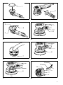
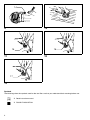
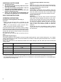
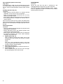
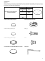
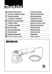
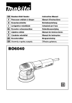
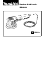
Random Orbit Sander
BO6040
DOUBLE
INSULATION
SPECIFICATIONS
Model
BO6040
Pad diameter .......................................................................................................................................... 150 mm
Abrasive disc diameter ........................................................................................................................... 150 mm
Orbits per minute ........................................................................................................................... 1,600 – 5,800
Overall length ......................................................................................................................................... 316 mm
Net weight ................................................................................................................................................. 2.7 kg
• Due to our continuing program of research and development, the specifications herein are subject to change without
notice.
• Note: Specifications may differ from country to country.
Power supply
The tool should be connected only to a power supply of the same voltage as indicated on the nameplate, and can only
be operated on single-phase AC supply. They are double-insulated in accordance with European Standard and can,
therefore, also be used from sockets without earth wire.
For European countries only
Noise and Vibration
The typical A-weighted sound pressure level is 78 dB (A).
The noise level under working may exceed 85 dB (A).
– Wear ear protection. –
The typical weighted root mean square acceleration
value is 7 m/s2.
EC-DECLARATION OF CONFORMITY
The undersigned, Yasuhiko Kanzaki, authorized by
Makita Corporation, 3-11-8 Sumiyoshi-Cho, Anjo, Aichi
446-8502 Japan declares that this product
(Serial No. : series production)
manufactured by Makita Corporation in Japan is in compliance with the following standards or standardized documents,
HD400, EN50144, EN55014, EN61000
in accordance with Council Directives, 73/23/EEC,
89/336/EEC and 98/37/EC.
Yasuhiko Kanzaki
CE 2000
MAKITA INTERNATIONAL EUROPE LTD.
Michigan Drive, Tongwell, Milton Keynes,
Bucks MK15 8JD, ENGLAND
2
1
2
1
2
3
5
6
4
3
4
8
9
7
5
6
13
12
11
8
10
7
8
3
14
9
10
16
15
11
12
17
13
Symbols
The following show the symbols used for the tool. Be sure that you understand their meaning before use.
❏ Read instruction manual.
❏ DOUBLE INSULATION
4
ENGLISH
Explanation of general view
1
2
3
4
5
6
Abrasive disc
Side grip
Screw
Pad
Hex wrench
Switch lever
7
8
9
10
11
12
Speed adjusting dial
Change knob
Roto-orbit mode
Random orbit mode
Dust outlet
Cuff
SAFETY INSTRUCTIONS
Warning! When using electric tools, basic safety precautions should always be followed to reduce the
risk of fire, electric shock and personal injury, including the following. Read all these instructions before
attempting to operate this product and save these
instructions.
For safe operation:
1. Keep work area clean
Cluttered areas and benches invite injuries.
2. Consider work area environment
Don’t expose power tools to rain. Don’t use power
tools in damp or wet locations. Keep work area well
lit. Don’t use power tools in presence of flammable
liquids or gases.
3. Guard against electric shock
Prevent body contact with grounded surfaces (e.g.
pipes, radiators, ranges, refrigerators).
4. Keep children away
Do not let visitors contact tool or extension cord. All
visitors should be kept away from work area.
5. Store idle tools
When not in use, tools should be stored in dry, high,
or locked-up place, out of the reach of children.
6. Don’t force tool
It will do the job better and safer at the rate for which
it was intended.
7. Use right tool
Don’t force small tools or attachments to do the job
of a heavy duty tool. Don’t use tools for purposes not
intended; for example, don’t use circular saw for cutting tree limbs or logs.
8. Dress properly
Do not wear loose clothing or jewelry. They can be
caught in moving parts. Rubber gloves and non-skid
footwear are recommendemd when working outdoors. Wear protective hair covering to contain long
hair.
9. Use safety glasses and hearing protection
Also use face or dust mask if cutting operation is
dusty.
10. Connect dust extraction equipment
If devices are provided for the connection of dust
extraction and collection facilities, ensure these are
connected and properly used.
11. Don’t abuse cord
Never carry tool by cord or yank it to disconnect it
from receptacle. Keep cord from heat, oil and sharp
edges.
12. Secure work
Use clamps or a vise to hold work. It’s safer than
using your hand and it frees both hands to operate
tool.
13. Don’t overreach
Keep proper footing and balance at all times.
13
14
15
16
17
Hose
Joint
Sponge pad
Felt pad
Wool pad
14. Maintain tools with care
Keep tools sharp and clean for better and safer performance. Follow instructions for lubricating and
changing accessories. Inspect tool cords periodically and, if damaged, have repaired by authorized
service facility. Inspect extension cords periodically
and replace if damaged. Keep handles dry, clean
and free from oil and grease.
15. Disconnect tools
When not in use, before servicing, and when changing accessories such as blades, bits and cutters.
16. Remove adjusting keys and wrenches
Form the habit of checking to see that keys and
adjusting wrenches are removed from tool before
turning it on.
17. Avoid unintentional starting
Don’t carry plugged-in tool with finger on switch. Be
sure switch is off when plugging in.
18. Outdoor use extension cords
When tool is used outdoors, use only extension
cords intended for use outdoors and so marked.
19. Stay alert
Watch what you are doing. Use common sense. Do
not operate tool when you are tired.
20. Check damaged parts
Before further use of the tool, a guard or other part
that is damaged should be carefully checked to
determine that it will operate properly and perform
its intended function. Check for alignment of moving
parts, binding of moving parts, breakage of parts,
mounting, and any other conditions that may affect
its operation. A guard or other part that is damaged
should be properly repaired or replaced by an authorized service center unless otherwise indicated elsewhere in this instruction manual. Have defective
switches replaced by and authorized service center.
Do not use tool if switch does not turn it on and off.
21. Warning
The use of any other accessory or attachment other
than recommended in this operating instruction or
the catalog may present a risk of personal injury.
22. Have your tool repaired by an expert
This electric appliance is in accordance with the relevant safety rules. Repairing of electric appliances
may be carried out only by experts otherwise it may
cause considerable danger for the user.
5
ADDITIONAL SAFETY RULES
1.
2.
3.
4.
5.
ENB042-2
Hold the tool firmly.
Do not leave the tool running. Operate the tool
only when hand-held.
This tool has not been waterproofed, so do not
use water on the workpiece surface.
Ventilate your work area adequately when you
perform sanding operations.
Always use the correct dust mask/respirator for
the material and application you are working with.
SAVE THESE INSTRUCTIONS.
OPERATING INSTRUCTIONS
Installing or removing abrasive disc (Fig. 1)
Important:
• Always be sure that the tool is switched off and
unplugged before installing or removing the abrasive
disc.
• Always use hook-and-loop system abrasive discs.
Never use pressure-sensitive abrasive discs.
To install the abrasive disc, first remove all dirt or foreign
matter from the pad. Then attach the abrasive disc to the
pad, using the hook-and-loop system of the abrasive disc
and the pad. Be careful to align the holes in the abrasive
disc with those in the pad.
To remove the disc from the pad, just pull up from its
edge.
Installing side grip (optional accessory)
(Fig. 2)
Remove one of the screws which secure the head cover.
Screw the side grip on the tool securely. The side grip
can be installed on either side of the tool.
Changing pad (Fig. 3)
Makita offers an extensive range of optional super soft,
soft and hard pads. Remove the screw counterclockwise
from the center of the base with a hex wrench. After
changing the pad, tighten the screw clockwise securely.
Switch action (Fig. 4)
CAUTION:
Before plugging in the tool, always check to see that the
switch lever actuates properly and returns to the “OFF”
position when the side of the switch control is depressed.
To start the tool, slide the switch lever to the “I” position.
For continuous operation, depress the front of the switch
lever and then slide to the “I” position as above.The
switch is used in this locked-on position for continuous
operation.
To stop the tool from this locked-on position, slide the
switch lever to the “O” position by depressing the rear of
the switch lever.
Speed adjusting dial (Fig. 5)
The rotating speed can be changed by turning the speed adjusting dial to a given number setting from 1 to 5. Higher
speed is obtained when the dial is turned in the direction of number 5. And lower speed is obtained when it is turned in
the direction of number 1.
Refer to the table below for the relationship between the number settings on the dial, orbits per minute and the pad
rotating speed.
Number
Orbits per min.
Roto-orbit pad rotating speed per min.
1
1,600
180
2
2,100
240
3
3,600
420
4
5,100
590
5
5,800
670
CAUTION:
• If the tool is operated continuously at low speeds for a long time, the motor will get overloaded and heated up.
• The speed adjusting dial can be turned only as far as 5 and back to 1. Do not force it past 5 or 1, or the speed adjusting function may no longer work.
6
Selecting action mode (Fig. 6 & 7)
Use the change knob to change the rotation mode. Roto-orbit mode is orbital action plus rotation action of pad for
rough sanding and polishing. Random orbit mode is orbital action of pad for fine sanding. Rotate the change knob
counterclockwise for roto-orbit mode and clockwise for random orbit mode.
CAUTION:
• Do not rotate the change lever when the tool is running under load. The tool will be damaged.
Typical applications for sanding and polishing
Sanding
Use / Material
Mode selection
Speed
control
setting
Pad
Paintwork:
Sanding
Repairs (scratches, rust spots)
Rough paint stripping
Random
Roto-orbit/Random
Roto-orbit
1–3
2–3
4–5
Soft
Hard
Soft
Plastics:
Soft plastics (PVC/ABS)
Hard plastics (FRP)
Roto-orbit/Random
Roto-orbit
1–3
1–3
Super soft/Soft
Soft/Hard
Woods:
Softwood
Hardwood
Veneers
Random
Roto-orbit/Random
Random
1–3
3–5
1–2
Super soft/Soft
Soft
Super Soft
Metals:
Non-ferrous metal (aluminum, copper)
Steel
Steel, rust removal
Hard metal (stainless steel)
Roto-orbit/Random
Roto-orbit
Roto-orbit
Roto-orbit
1–3
3–5
4–5
4–5
Soft
Soft/Hard
Super soft
Soft
Polishing
Use / Material
Mode selection
Speed
control
setting
Pad
Applying wax
Roto-orbit
2–4
Sponge pad
Removing wax
Roto-orbit
4–5
Felt pad
Polishing
Roto-orbit
4–5
Wool pad
The above information is intended only as a guide. In each case, the most appropriate sanding disc grain should be
determined by preliminary trials.
The tool equipped with electronic function is easy to operate because of the following features.
• Constant speed control
Electronic speed control for obtaining constant speed.
Possible to get fine finish, because the rotating speed is kept constant even under load condition.
• Soft start feature
Safety and soft start because of suppressed starting shock.
7
Dust collection (optional accessory)
(Fig. 8 & 9)
If a Makita hose is used, you can connect the cuff to the
dust outlet directly. If other hose with an inner diameter of
24 mm, attach the joint between the dust outlet and the
cuff.
Sanding operation (Fig. 10)
CAUTION:
• Never switch on the tool when it is in contact with the
workpiece, it may cause an injury to operator.
• Never run the tool without the abrasive disc. You may
seriously damage the pad.
• Never force the tool. Excessive pressure may decrease
the sanding efficiency, damage the abrasive disc or
shorten tool life.
Turn the tool on and wait until it attains full speed. Then
gently place the tool on the workpiece surface. Keep the
pad flush with the workpiece and apply slight pressure on
the tool.
Polishing operation
CAUTION:
• Use only a Makita genuine sponge pad, felt pad or wool
pad (optional accessories).
• Always operate the tool at low speed to prevent work
surfaces from heating abnormally.
• Never force the tool. Excessive pressure may decrease
the polishing efficiency and cause motor overload,
resulting in tool malfunction.
1. Applying wax (Fig. 11)
Use an optional sponge pad. Apply wax to the
sponge pad or work surface. Run the tool to smooth
out the wax.
NOTE:
First, wax a less conspicuous portion of the work
surface to make sure that the tool will not scratch the
surface or result in uneven waxing.
2. Removing wax (Fig. 12)
Use an optional felt pad. Run the tool to remove wax.
3. Polishing (Fig. 13)
Use an optional wool pad. Run the tool and apply
the wool pad gently to the work surface.
8
MAINTENANCE
CAUTION:
Always be sure that the tool is switched off and
unplugged before carrying out any work on the tool.
To maintain product safety and reliability, repairs, maintenance or adjustment should be carried out by a Makita
Authorized Service Center.
ACCESSORIES
CAUTION:
These accessories or attachments are recommended for use with your Makita tool specified in this manual. The use of
any other accessories or attachments might present a risk of injury to persons. The accessories or attachments should
be used only in the proper and intended manner.
Grit
Use
40
Coarse
60
• Hook-and-loop system abrasive disc
(with pre-punched holes)
80
Medium
120
180
240
Fine
400
• Hook-and-loop system sponge pad
• Pad 150 (Super soft, Soft, Hard)
• Hook-and-loop system felt pad
• Side grip
• Hook-and-loop system wool pad
• Joint
• Sanding cloth 150 – #100, #200, #800 for fine sanding
• Hex wrench
9
UK only
DOUBLE INSULATION
THE ADDITIONAL COMMENT OF ELECTRICAL CONNECTION
The tool is double insulated for safety, no earth connection is required.
CAUTION:
The tool must be connected to a plug having a rated current greater than that of tool.
The rated voltage and current appear on the name plate.
IMPORTANT: The wires in the mains lead are coloured in accordance with the following code.
NOTE:
CAUTION:
10
As the colours of the mains lead of the tool may not correspond with the coloured markings identifying
the terminals in your plug, proceed as follows:
THE WIRE WHICH IS COLOURED BLUE MUST BE CONNECTED TO THE TERMINAL WHICH IS
MARKED WITH THE LETTER “N” OR COLOURED BLACK. THE WIRE WHICH IS COLOURED
BROWN MUST BE CONNECTED TO THE TERMINAL WHICH IS MARKED WITH THE LETTER “L” OR
COLOURED RED.
Neither wire is to be connected to earth terminal which is marked with the letter “E” or symbol “
”.
FOR 110 VOLT TOOL, USE PLUGS TO BS4343.
11
Makita Corporation
Anjo, Aichi, Japan
Made in Japan
884338A9