1
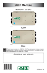
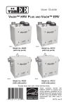
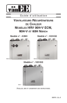
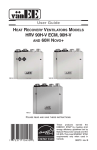
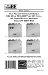
USER GUIDE
®
VB0110
BRONZE MODELS
90H*
190H
READ
AND SAVE THESE INSTRUCTIONS
*This product earned the ENERGY STAR® by
meeting strict energy efficiency guidelines set
by Natural Resources Canada and the US EPA.
It meets ENERGY STAR requirements only when
used in Canada.
03450 rev. C
CONGRATULATIONS! You have made an excellent choice!
We have prepared this User Guide especially for you. Please read it carefully to ensure you obtain full benefits from your
Heat Recovery Ventilator unit.
About this Guide
This guide uses the following symbols to emphasize particular information:
! WARNING
Identifies an instruction which, if not followed, might cause serious personal injuries including possibility of
death.
CAUTION
Denotes an instruction which, if not followed, may severely damage the unit and/or its components.
NOTE: Indicates supplementary information needed to fully complete an instruction.
TABLE OF CONTENTS
1.
UNIT DESCRIPTION . . . . . . . . . . . . . . . . . . . . . . . . . . . . . . . . . . . . . . . . . . . . . . . . . . . . . . . . . .3
1.1 SPECIFICATIONS . . . . . . . . . . . . . . . . . . . . . . . . . . . . . . . . . . . . . . . . . . . . . . . . . . . . . . . . . . . . . . . . . . . . . . . . . . .3
2.
FUNCTION OF THE HEAT RECOVERY VENTILATOR . . . . . . . . . . . . . . . . . . . . . . . . . . . . . . .3
2.1 HEAT RECOVERY . . . . . . . . . . . . . . . . . . . . . . . . . . . . . . . . . . . . . . . . . . . . . . . . . . . . . . . . . . . . . . . . . . . . . . . . . .3
2.2 DEFROSTING . . . . . . . . . . . . . . . . . . . . . . . . . . . . . . . . . . . . . . . . . . . . . . . . . . . . . . . . . . . . . . . . . . . . . . . . . . . . .3
3.
CONTROLS . . . . . . . . . . . . . . . . . . . . . . . . . . . . . . . . . . . . . . . . . . . . . . . . . . . . . . . . . . . . . . .4-6
3.1 INTEGRATED CONTROL . . . . . . . . . . . . . . . . . . . . . . . . . . . . . . . . . . . . . . . . . . . . . . . . . . . . . . . . . . . . . . . . . . . . . .4
3.1.1 BOOT SEQUENCE . . . . . . . . . . . . . . . . . . . . . . . . . . . . . . . . . . . . . . . . . . . . . . . . . . . . . . . . . . . . . . . . . . . . .4
3.2 OPTIONAL MAIN WALL CONTROLS . . . . . . . . . . . . . . . . . . . . . . . . . . . . . . . . . . . . . . . . . . . . . . . . . . . . . . . . . . . . . .4
3.2.1 LITE-TOUCH BRONZE . . . . . . . . . . . . . . . . . . . . . . . . . . . . . . . . . . . . . . . . . . . . . . . . . . . . . . . . . . . . . . . . . .4
3.2.2 BRONZE . . . . . . . . . . . . . . . . . . . . . . . . . . . . . . . . . . . . . . . . . . . . . . . . . . . . . . . . . . . . . . . . . . . . . . . . . . .5
3.3 OPTIONAL AUXILIARY CONTROLS . . . . . . . . . . . . . . . . . . . . . . . . . . . . . . . . . . . . . . . . . . . . . . . . . . . . . . . . . . . . . . .6
3.3.1 HUMIDITY CONTROL . . . . . . . . . . . . . . . . . . . . . . . . . . . . . . . . . . . . . . . . . . . . . . . . . . . . . . . . . . . . . . . . . . .6
3.3.2 20-MINUTE LIGHTED PUSH BUTTON . . . . . . . . . . . . . . . . . . . . . . . . . . . . . . . . . . . . . . . . . . . . . . . . . . . . . . .6
3.3.3 60-MINUTE MECHANICAL TIMER . . . . . . . . . . . . . . . . . . . . . . . . . . . . . . . . . . . . . . . . . . . . . . . . . . . . . . . . . .6
4.
MAINTENANCE . . . . . . . . . . . . . . . . . . . . . . . . . . . . . . . . . . . . . . . . . . . . . . . . . . . . . . . . . . . . . .7
4.1
4.2
5.
REGULAR . . . . . . . . . . . . . . . . . . . . . . . . . . . . . . . . . . . . . . . . . . . . . . . . . . . . . . . . . . . . . . . . . . . . . . . . . . . . . . . .7
PROLONGED . . . . . . . . . . . . . . . . . . . . . . . . . . . . . . . . . . . . . . . . . . . . . . . . . . . . . . . . . . . . . . . . . . . . . . . . . . . . . .7
TROUBLESHOOTING . . . . . . . . . . . . . . . . . . . . . . . . . . . . . . . . . . . . . . . . . . . . . . . . . . . . . . . . .8
CAUTION
1. Some activities create dust or vapors which may damage your unit. You must, therefore, turn off and unplug
your unit in the following situations:
• major renovation work • housing construction
• sanding (e.g. gypsum joints, etc.)
• varnishing
2. During heavy snow storms, turned off the unit to avoid problems caused by snow penetration, even if it is
equipped with anti-gust intake hood.
3. Power disturbances or very short power failures may cause the electronic control microprocessor to malfunction.
If it does, disconnect the power plug from the outlet and wait approximately 30 seconds, then plug it back in
to resume operation.
2
1.
UNIT DESCRIPTION
1
1. Filters
2. Blowers
3. Condensation tray
4. Heat recovery core
4
2
1
1
3
VB0097
1.1 SPECIFICATIONS
MODEL
WIDTH
HEIGHT
DEPTH
WEIGHT
ELECTRICAL SUPPLY
POWER CONSUMPTION
2.
FUNCTION
OF THE
90H
30¼’’ (768 MM)
16½’’ (419 MM)
17¼’’ (438 MM)
66 LB (30 KG)
120 V, 60 HZ
150 W
190H
30¼’’ (768 MM)
16½’’ (419 MM)
17¼’’ (438 MM)
68 LB (30 KG)
120 V, 60 HZ
240 W
HEAT RECOVERY VENTILATOR
Your ventilation system will help eliminate poor air quality problems by
drawing the stale and humid air out of the house and replacing it with fresh
outside air. By eliminating accumulated pollutants and humidity, it maintains
an optimum air quality and an ideal relative humidity during cold season.
The unit is also equipped with a heat recovery core which reduces ventilation
costs in winter.
Shown with a forced air heating system; can also operate on its own.
VH0006
2.1 HEAT RECOVERY
Example: (in winter)
Units equipped with a heat recovery core can reduce
ventilation costs in winter. The unit draws the heat from the
stale air and humid air before it is released and uses it to
heat the air coming in from outside. The recovery core is
designed in such a way that the stale air is never mixed with
the fresh air.
Exhaust air to outside
6°C/43°F
Fresh air to building
16°C/61°F
Fresh air from outside
0°C/32°F
Exhaust air from building
22°C/72°F
VF0026
2.2 DEFROSTING
When the outside temperature is below -5°C (23°F), heat recovery creates frost in the core. To maintain its proper operation, the unit is
programmed to defrost the recovery core. The defrosting frequency varies according to outside temperature. Defrosting lasts 7 or 10 minutes,
according to outside temperature. During the defrost cycle, the unit shifts to maximum speed and the dampers close.
After defrosting, the unit returns to the operating mode previously selected by the user.
3
3.
CONTROLS
3.1 INTEGRATED CONTROL
2
1
All units are equipped with an integrated control, located in front of the electrical compartment. Use the push
button (1) to control the unit. The LED (2) will then shows on which mode the unit is in.
VD0193
Refer to table below to see how to operate the unit using its integrated control.
PRESS
ON PUSH BUTTON
ONCE
TWICE
THREE TIMES
LED COLOR
AMBER
GREEN
NO LIGHT
RESULTS
UNIT IS ON LOW SPEED
UNIT IS ON HIGH SPEED
UNIT IS OFF
If a problem occurs during the unit operation, its integrated control LED (2) will blink. The color of the blinking light depends on the type
of error detected. Refer to Section 5 Troubleshooting on last page for further details.
3.1.1 BOOT
SEQUENCE
The unit boot sequence is similar to a personnal computer boot sequence. Each time the unit is plugged after being unplugged, or
after a power failure, the unit will perform a 30-second booting sequence before starting to operate. During the booting sequence, the
integrated control LED will light GREEN or AMBER for 5 seconds, and then will shut off for 2 seconds. After that, the LED will light RED
for the rest of the booting sequence. During this RED light phase, the unit is checking and resetting the motorized damper position.
Once the motorized damper position completely set, the RED light turns off and the booting sequence is done.
NOTE: No command will be taken until the unit is fully booted.
3.2 OPTIONAL MAIN WALL CONTROLS
For more convenience, this unit can also be controlled using an optional main wall control.
NOTES: 1. The integrated control must be turned OFF to use an optional main control.
2. If an optional auxiliary control is used, if activated, this auxiliary control will override the optional main control.
3.2.1 LITE-TOUCH BRONZE
Location: Located in the busiest area of the house.
Purpose: To adjust air supply.
Activate the push-button. The color of the indicator shows the unit operating mode.
Color
Mode
Suggested Use
Green
Intermittent Select this mode when you are away from the house for a few days. Also, when
you deem the inside air is too dry in heating season, or too humid in cooling season.
In this mode, the unit is OFF for 40 minutes per hour and ventilates at minimum
speed the remaining 20 minutes of the hour.
Yellow
Min. Speed For normal daily operation.
Ventilation
Red
Max. Speed For excess pollutants and humidity (parties, odors, smoke, etc.).
Ventilation
MAX
MIN
INTERMITTENT
L-T
®
VC0080
4
3.
CONTROLS
(CONT’D)
3.2 OPTIONAL MAIN WALL CONTROLS (CONT’D)
3.2.2 BRONZE
Location: Located in the busiest area of the house.
Purpose: To adjust air supply and select desired indoor humidity level.
%
b) To turn the unit off, place selector at the OFF position. However, if optional auxiliary controls
are used, they will still be active.
5°C+
41°F+
MFO RT ZONE
HUMIDITY
CONTROL
20%
25%
CO
Adjusting the AIR SUPPLY CONTROL:
a) Select speed MIN. or MAX. using switch A (as shown on diagram).
• Select speed MIN. (minimum speed) for normal daily operation (24 hours a day all year round).
• Select MAX. (maximum speed) for excess pollutants and humidity (parties, odors, smoke, etc.)
ATIVE HUM ID IT
REL
Y
F
OF
RE HUMID
MO
-5°C
30%
23°F
70%
CO
M FO R T Z ON E
40%
LES
S H U MID
60%
50%
-20°C
-4°F
-30°C
-22°F
B
MAX.
OFF
DURING FALL, WINTER
AND SPRING, SET THE
DIAL ACCORDING TO
THE DESIRED MAXIMUM
INDOOR HUMIDITY LEVEL.
DURING SUMMER SET
THE DIAL TO THE
OFF POSITION.
A
MIN.
Adjusting the HUMIDITY CONTROL:
VC0039
Setting during the summer months:
Normally, there is no condensation on your windows during this period which, therefore, eliminates the need of the humidity control.
Set the slide switch A to OFF position during this period (do not exchange in day time, exchange at night time if cool outside or if it is not
raining).
Setting during the fall, winter and spring months:
•
METHOD 1 (fast and simple for new users):
a) Determine approximately the outside daytime temperature.
b) Set knob B to this temperature.
NOTE: Continue using this method for about a month before trying Method 2 suggested below.
•
METHOD 2 (more precise adjustment):
Use METHOD 2 (steps a to f below) if there is condensation on your windows after using METHOD 1 for at least
1 month. As ventilation needs vary from one house to another (depending on cooking habits, frequency of showers,
washing, window design, etc.), an adjustment based on outside temperature may not adequately solve the condensation
problem in your house.
a) Select speed MIN.
b) Turn knob B clockwise until you hear a click.
c) Turn knob B a notch below the click.
d) 12 to 24 hours later, check if there is still condensation on the windows.
e) If there is, repeat steps b, c, d above (until desired results are obtained).
f) Compare the two values: the one obtained with METHOD 1 and the other with METHOD 2. Use the variance for
future reference. For example, if there is a 3-degree variance, you can conclude that, for your house, an adjusment
of 3 degrees below the outside temperature is required for optimum condensation control.
CAUTION
Do not select a temperature below -20°C. This could lead to excessive dryness in the air causing discomfort for
the occupants.
It is possible (and normal) to experience condensation on your windows when drastic changes in temperature occur (e.g.: -5°C [23°F]
to -20°C [-4°F]). In that case, we suggest waiting a few days to allow the situation to stabilize.
5
3.
CONTROLS
(CONT’D)
3.3 OPTIONAL AUXILIARY CONTROLS
3.3.1 Humidity Control
Location: Located in the bathroom or in other locations where there is temporary humidity
excess.
Purpose: To eliminate excess humidity produced by showers or other periodic activities
producing humidity.
%
ATIVE HUM ID IT
REL
Y
F
OF
20%
HUMIDITY
CONTROL
25%
70%
30%
Adjust knob to the desired humidity level.
CO
M FO R T
40%
CAUTION
Do not select a humidity level below 30%. This could lead to excessive dryness
in the air causing discomfort for the occupants.
DURING FALL, WINTER
AND SPRING, SET THE
DIAL ACCORDING TO
THE DESIRED MAXIMUM
INDOOR HUMIDITY LEVEL.
DURING SUMMER SET
THE DIAL TO THE
OFF POSITION.
VC0038
3.3.2 20-Minute Lighted Push Button
Location: Located in the bathroom or in other locations where there is temporary humidity excess
or pollutants.
Purpose: To eliminate excess humidity produced by showers or other periodic activities
producing pollutants.
ON
Press once to activate the push-button. The unit will operate on high speed for 20 minutes and the
indicator will light up. To stop activation before the end of the 20-minute cycle, push one more time.
The unit will get back to its previous setting.
®
VENTILATION
VC0040
3.3.3 60-Minute Crank timer
Location: Located in the bathroom or in other locations where there is temporary humidity excess
or pollutants.
Purpose: To eliminate excess humidity produced by showers or other periodic activities
producing pollutants.
OFF
Turn
Past
HOLD
10
60
20
50
40
This control makes the system operate at high speed for periods varying from 10 to 60 minutes.
MINUTES
VC0017
6
30
E
Z ON
50%
60%
4.
MAINTENANCE
! WARNING
In order to prevent personal injury, turn off the unit and unplug it before performing maintenance. When cleaning
the unit, it is recommended to wear safety glasses and gloves.
4.1 REGULAR
Air filters: The air filters are washable. Under normal conditions, we recommend to wash them every 3 months.
•
Use a vacuum cleaner to remove the heaviest portion of accumulated dust.
•
Then, wash in water and mild soap.
•
Let dry completely before reinstalling them in the unit.
Heat Recovery Core:
CAUTION
Hot water and a strong detergent will damage the heat recovery core.
The heat recovery core must be handled with care. We recommend to wash it once a year, at the end of summer, in order to ensure
maximum efficiency of the plastic partitions. Allow the heat recovery core to soak for 3 hours in a solution of warm water and mild soap.
Rinse under a heavy stream of water. Let dry completely before reinstalling it in the unit.
NOTE: When plugging back the unit, it will return to its previous setting after a 30-second delay for boot sequence.
Intake hood: Regularly check the screen in the exterior intake hood and clean when necessary. Also check during very cold weather
because ice may build up on the screen located in the exterior intake hood.
Motor: The motor is factory lubricated for life. Do not oil bushings.
4.2 PROLONGED
Annual service should include:
•
Cleaning filters, heat recovery core and the exterior intake hood.
•
Cleaning the blades of the blower wheels.
•
Cleaning the condensation tray with soapy water (make sure that the drain is not clogged).
NOTE: Ask your installer for an annual service contract.
7
5.
TROUBLESHOOTING
If you think your unit is malfunctioning, check some of the following:
1
2
TYPE OF PROBLEM
Nothing works.
Condensation on windows
(air too humid).
•
•
•
•
•
•
•
•
•
•
•
•
•
•
•
TRY THIS...
See if the unit is plugged in.
See if the breaker is receiving power from the house circuit breaker.
Adjust the humidity control knob as per instructions (see Section 3.).
Operate the unit at maximum speed (MAX.) during activities generating excess humidity
(family gatherings, extra cooking, etc.)
Leave curtains half-open to allow air circulation.
Store all firewood in a closed room with a dehumidifier or in a well ventilated room or store
the wood outside.
Do not adjust the thermostat of your heating system below 18°C (64°F).
Do not adjust your humidity control below -20°C (-4°F).
Operate the unit at low speed (MIN). or in intermittent mode (with Lite-Touch Bronze).
Temporarily use a humidifier.
Make sure the stale air exhaust hood outside the house is not blocked.
Operate the unit at low speed (MIN.) or in intermittent mode (with Lite-Touch Bronze).
Have the system’s balancing checked.
Have the unit’s defrosting system checked.
Install a duct heater.
3
Air too dry.
4
Air too cold at the air
supply grille.
5
The LED of the integrated
control is blinking red.
• There is a problem with the motor. The unit is OFF. Contact your installer.
6
The LED on the integrated
control is blinking green.
• There is a problem with the thermistor. The unit is still working, but is always in defrost
mode. Contact your installer.
7
The LED on the integrated
control is blinking amber.
• There is a problem with the motorized damper. The unit is OFF. For a 12-hour period,
the unit will try to reset the damper at every 20 to 30 minutes. After 12 hours, if the
problem is not solved, the unit stops trying to reset damper. Contact your installer.
8
The integrated control
push button does not work.
• The 30-second boot sequence is not completed. See integrated control on page 4.
If the problem continues, contact your installer at the phone number and address listed below or call the following number for authorized
service center nearest you:
•
1-800-567-3855 (CANADA AND U.S.A.)
YOUR INSTALLER’S ADDRESS
REPLACEMENT PARTS
AND
REPAIR
In order to ensure your ventilation unit remains in good working condition, you must use vänEE genuine replacement parts only.
The vänEE genuine replacement parts are specially designed for each unit and are manufactured to comply with all the applicable
certification standards and maintain a high standard of safety. Any third party replacement part used may cause serious damage and
drastically reduce the performance level of your unit, which will result in premature failing. Also, vänEE recommends to contact a
certified service depot for all replacement parts and repairs.
8