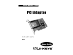
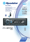
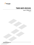
1
RS-R8C25-2200 – Ultra Low Power Wi-Fi Starter Kit for R8C/25 User Guide for Wi-Fi I/O Companion Card with R8C/25 Version 1.0 April ’10 Redpine Signals, Inc. 2107 N. First Street, #680 San Jose, CA 95131. Tel: (408) 748-3385 Fax: (408) 705-2019 Email: [email protected] Website: www.redpinesignals.com Redpine Signals, Inc. Proprietary and Confidential RS-R8C25-2200 – Ultra Low Power Wi-Fi Starter Kit for R8C/25 User Guide for Wi-Fi I/O Companion Card with R8C/25 Overview The Wi-Fi I/O Companion Card for the R8C/25 has Redpine Signals’ Connectio-n™ module, RS9110-N-11-22, mounted. It is a complete IEEE 802.11bgn based wireless device server that directly provides a wireless interface to any equipment with a serial or SPI interface for data transfer. It integrates a MAC, baseband processor, RF transceiver with power amplifier, a frequency reference, and an antenna in hardware; and all WLAN protocol and configuration functionality, networking stack in embedded firmware to make a fully self-contained 802.11n WLAN solution for a variety of applications. Applications: Seamless Wi-Fi connectivity for Application Processors Industrial M2M communications Point of Sale Terminals Metering (Parking Meters, Utility Meters, Power Meters, etc.) Security Cameras and Surveillance Equipment Logistics and Freight Management Warehousing Digital Picture Frames Several medical applications including Patient Monitoring, Remote Diagnostics Device Features: Compliant to 802.11b/g and single stream draft 802.11n Fully self-contained serial-towireless functionality Includes all the protocol and configurations functions for WLAN connectivity in Open, WEP and WPA/WPA2-PSK modes of operation Payload data through Serial Interface and SPI Terminates TCP and UDP connections, and offers transparent serial modem functionality Configuration through UART of Wireless means Bluetooth coexistence support Integrated antenna, frequency reference and low-frequency clock Ultra-low-power operation with power-save modes Ad-hoc and infrastructure modes for maximum deployment flexibility Single supply – 3.1 to 3.6V operation RS9110-N-11-22 System Block Diagram GPIO BT Coexistence I/f Host Processor Serial I/f SPI/UART Selection UART Port Applications RF RS9110 Transceiver SPI Host I/f 3.3V Supply Reset TCP/IP WLAN Stack RF FE Flash RS9110 WLAN Subsystem Reset XO LED Flash RS9110-N-11-22 Test Port Redpine Signals, Inc. Proprietary and confidential Page 2 RS-R8C25-2200 – Ultra Low Power Wi-Fi Starter Kit for R8C/25 User Guide for Wi-Fi I/O Companion Card with R8C/25 Table of Contents 1: Introduction ......................................................................... 5 1.1: Scope ....................................................................................... 6 1.2: Limitations............................................................................... 6 2: System Overview ................................................................. 7 3: Getting Started..................................................................... 9 3.1: R8C/25 MCU Software ............................................................. 9 3.2: Demo Application..................................................................... 9 3.3: Test Setup and Evaluation........................................................ 9 3.3.1: Evaluation Procedure.................................................................. 3.3.1.1: Auto Connect Mode ............................................................... 3.3.1.2: Manual Mode......................................................................... 3.3.1.3: Wireless Reconfiguration ...................................................... 10 11 13 18 4: Components on the Companion Card and their Usage ........ 20 4.1: DIP Switches ......................................................................... 20 5: Contact and Support Information ....................................... 21 Redpine Signals, Inc. Proprietary and confidential Page 3 RS-R8C25-2200 – Ultra Low Power Wi-Fi Starter Kit for R8C/25 User Guide for Wi-Fi I/O Companion Card with R8C/25 Table of Figures Figure 1: Connect-io-n (RS9110-N-11-22) Software Architecture ................ 7 Figure 2: Test setup for TCP/IP Evaluation ................................................ 10 Figure 3: R8C/25 Board with Wi-Fi Companion Card and LCD module mounted..................................................................................................... 11 Figure 4: R8C/25 MCU Board and the LEDs ................................................ 12 Figure 5: Demo Application ........................................................................ 13 Figure 6: Navigate to the RSR8C252200DEMO Workspace ......................... 14 Figure 7: HEW Workspace .......................................................................... 15 Figure 8: Contents of the network_config.h file ......................................... 16 Figure 9: Debug Settings............................................................................ 17 Figure 10: Wi-Fi Tab of the Demo Application ............................................ 18 Figure 11: Wireless Reconfiguration .......................................................... 19 Figure 12: Figure 6: Components on the R8C25 Companion Card ............... 20 Redpine Signals, Inc. Proprietary and confidential Page 4 RS-R8C25-2200 – Ultra Low Power Wi-Fi Starter Kit for R8C/25 User Guide for Wi-Fi I/O Companion Card with R8C/25 1: Introduction This User Guide takes the user through the process of setting up the demo of the RS-R8C25-2200 Wi-Fi Starter Kit. The components of the kit are as follows: CPU Board with R8C/25 Companion Card with RS9110-N-11-22 Detachable LCD Display Module Detachale AD Adjustment Shaft E8a Emulator Connection Cable (USB Cable, User Interface Cable) Power Supply Printed Quick-Start Guide CD-ROM o Documents: Datasheet, API Library Manual, User Manual and more o IDE: High-performance Embedded Workshop o API Library for Wi-Fi Module o Sample Code o Demo Application and Firmware o C Compiler (Evaluation Version) o Flash Memory Programmer: Flash o Development Toolkit Evaluation Version The kit comes with two CDs – one with the Renesas Electronics label and the other with the Redpine Signals label. The Renesas CD contains all the software and documentation required to use the R8C/25 MCU board. Please refer to the documentation provided in the CD to know more on the usage of the board and related components. The Redpine Signals CD contains the following: 1. Documents a. RS9110-N-11-22 Module Datasheet b. Quick Start Guide for the Wi-Fi Starter Kit c. Companion Card User Guide (this document) d. API Library Manual 2. Software a. Demo Redpine Signals, Inc. Proprietary and confidential Page 5 RS-R8C25-2200 – Ultra Low Power Wi-Fi Starter Kit for R8C/25 User Guide for Wi-Fi I/O Companion Card with R8C/25 i. Applications – this folder contains the Demo application. The application has been explained in this document. ii. R8C25_SW_App – this folder contains the application software for the R8C/25 for the demo. It has sample source code on how to program the Companion Card using the API Library b. Lib – this folder contains the API Library files c. RS9110-N-11-22_Firmware – this folder contains the firmware for the Wi-Fi module on the Companion Card. The procedure to upgrade the firmware on the Wi-Fi module will be provided in future releases. 1.1: Scope The scope of this document is to guide the user in setting up the R8C/25 + Connect-io-n Companion Card Kit and use the supplied applications to perform the evaluation. 1.2: Limitations 1. The maximum number of Access Points that can be displayed on the Demo Application’s GUI is 4. This can be increased in future releases. 2. Power-save features are not supported in the current software release, although the module’s firmware supports these features. These will be added in future releases. 3. The UART/SPI ports of the Renesas Electronics MCUs that are used to communicate with the Redpine Wi-Fi modules are fixed in the present release. In the future, the user will be given the option of selecting the port to be used on each MCU. 4. The software for upgrading the firmware of the Wi-Fi Companion Card will be provided in the next release of the software. Redpine Signals, Inc. Proprietary and confidential Page 6 RS-R8C25-2200 – Ultra Low Power Wi-Fi Starter Kit for R8C/25 User Guide for Wi-Fi I/O Companion Card with R8C/25 2: System Overview The following diagram depicts the software architecture of the Connect-ion 1 module, RS9110-N-11-22, used in the Ultra Low Power Wi-Fi Starter Kit for Renesas Electronics’ MCUs. Renesas Host Controller (HOST) Application UART/SPI Driver UART/SPI UART/SPI Host Abstraction Layer SLIP Wireless Control Block Station Managment Entity TCP/IP WPA/WPA-2 802.11 b/g/n MAC Connect-io-n (RS9110-N-11-22) Figure 1: Connect-io-n (RS9110-N-11-22) Software Architecture 1 Mention of Connect-io-n module in this document specifically refers to the RS9110N-11-22 module, although Connect-io-n, in general, refers to a family of 8 modules. Please visit www.redpinesignals.com/connection.html for further details. Redpine Signals, Inc. Proprietary and confidential Page 7 RS-R8C25-2200 – Ultra Low Power Wi-Fi Starter Kit for R8C/25 User Guide for Wi-Fi I/O Companion Card with R8C/25 As shown in the figure above, the Connect-io-n module is integrated with the Host using either UART or SPI interfaces 2 . The transmission and reception of the data to/from the Host depends on the interface used to connect the module as briefed below. UART mode: The Host transmits/receives raw data using UART interface when Connectio-n is configured for UART mode. The access to the TCP/IP stack in the Wi-Fi module through UART is provided through AT commands. SPI mode2: Host transmits/receives raw data when RS9110-N-11-22 is configured for SPI mode. A thin driver on the Host takes care of interacting with the WiFi module through the SPI Host interface. 2 The RS-R8C25-2200 Wi-Fi Starter Kit is available for the UART interface only. The kit with SPI will be released in the future. Redpine Signals, Inc. Proprietary and confidential Page 8 RS-R8C25-2200 – Ultra Low Power Wi-Fi Starter Kit for R8C/25 User Guide for Wi-Fi I/O Companion Card with R8C/25 3: Getting Started The system requirements for this demo are as follows: 1. RS-R8C25-2200 Wi-Fi Starter Kit 2. Laptop with Windows™ 2000/XP/Vista WLAN interface enabled JRE 1.6.0 installed – you might require administrator privileges to install this if it’s not already installed. 3.1: R8C/25 MCU Software The R8C/25 MCU platform comes preloaded with the demo application software for connection to an Access Point, LED-control and socket interface application. It’s also loaded with the API library which is used to configure the Wi-Fi module and use it to exchange data with a Peer Laptop/PC. The application software and the library are both present in the Redpine Signals CD, supplied as part of the kit. 3.2: Demo Application The Starter kit is supplied with the R8C/25 Demo Application GUI. The Application is a Java-based application for Windows™ 2000/XP/Vista. It has to be executed on the Peer Laptop/PC after installing JRE 1.6.0. The application has two tabs – DEMO and Wi-Fi. These are explained below. 1. This GUI runs on the Laptop/PC and it communicates with the Starter Kit over the network. 2. The “DEMO” tab is used for LED demo. 3. The “Wi-Fi” tab displays the list of Access Points in the vicinity and the RSSI value for each Access Point (both as seen by the Connect-io-n module). 4. The “Wi-Fi” tab can also be used to reconfigure the Starter Kit with new WLAN and network settings. This is explained in subsequent sections. 3.3: Test Setup and Evaluation The figure below illustrates the test setup. Redpine Signals, Inc. Proprietary and confidential Page 9 RS-R8C25-2200 – Ultra Low Power Wi-Fi Starter Kit for R8C/25 User Guide for Wi-Fi I/O Companion Card with R8C/25 Laptop/PC (Peer) R8C/25 + WiFi I/O Companion Card Access Point Figure 2: Test setup for TCP/IP Evaluation 3.3.1: Evaluation Procedure The demo can be executed in two ways – auto connect and manual modes. The auto connect mode involves just mounting the Wi-Fi Companion Card on the R8C/25 Board and powering it on. The Board automatically connects to the nearest Open Access Point and displays the SSID and the IP Address on the LCD display of the Board. In the manual mode, the user can configure the MCU software to connect to a particular Access Point in Open or Secure modes. Copy the files on the Redpine Signals CD to the Laptop to the folder C:\Workspace Mount the Wi-Fi Companion Card on the JA1 Header of the R8C/25 Board and the LCD Display Module on the LCD Header as shown here. Please ensure that the orientation of the cards is exactly as shown in the image. Also ensure that the Wi-Fi Companion Card is mounted before the LCD module to ensure proper mounting. Redpine Signals, Inc. Proprietary and confidential Page 10 RS-R8C25-2200 – Ultra Low Power Wi-Fi Starter Kit for R8C/25 User Guide for Wi-Fi I/O Companion Card with R8C/25 RS9110-N-11-22 Module R8C/25 MCU Board Wi-Fi Companion Card LCD Display Module JA1 Header of the R8C/25 MCU Board Figure 3: R8C/25 Board with Wi-Fi Companion Card and LCD module mounted 3.3.1.1: Auto Connect Mode 1. Power on the R8C/25 Board. The Power LED glows first. Next, the Companion Card boots up and connects to an Open Access Point with the strongest signal strength. The SSID of the Access Point and the IP address of the Kit are displayed on the LCD Module – IP address is acquired through DHCP. This can take a couple of seconds. During this time, the LCD module displays “Searching for APs…” If no Open Access Point is found or connection to the available Open Access Points fails because of access restrictions or DHCP being disabled, the LCD Module displays “NO OPEN AP FOUND” or “IPCONF ERROR”. If an error has to be displayed, it can take some time, especially in the case of “IPCONF ERRROR” since the DHCP client has to timeout. If this is the case, switch to the manual mode of the demo. Redpine Signals, Inc. Proprietary and confidential Page 11 RS-R8C25-2200 – Ultra Low Power Wi-Fi Starter Kit for R8C/25 User Guide for Wi-Fi I/O Companion Card with R8C/25 Power LED LED 0 LED 1 LED 2 App LED Figure 4: R8C/25 MCU Board and the LEDs 2. If the connection to the Access Point is successful, connect the Laptop to the same Access Point over WLAN or using an Ethernet cable. 3. Double-click on the R8CGUI.jar file present in the Software>Demo->Applications folder. A window opens, as shown here. Enter the IP address of the MCU board (displayed on its LCD Module) in the field marked “Device IPv4 Address”. Next, click the “Connect” button. The LED marked “App LED” will glow on the MCU Board to signal a connection being established between the Demo Application on the Laptop and the MCU Board. Redpine Signals, Inc. Proprietary and confidential Page 12 RS-R8C25-2200 – Ultra Low Power Wi-Fi Starter Kit for R8C/25 User Guide for Wi-Fi I/O Companion Card with R8C/25 Figure 5: Demo Application 4. Clicking on the positions of LED 0, LED 1 and LED 2 on the Demo Application on the Laptop toggles the corresponding LEDs on the MCU Board. 5. Clicking on the “Disconnect” button on the Demo Application disconnects the socket-level communications between the Application and the MCU. This is signalled by the App LED not glowing. If you have been able to successfully connect to an Open mode Access Point, please skip to the Wireless Reconfiguration section. If the connection was not successful or if you want to connect to a particular Access Point, please continue reading the Manual Mode section. 3.3.1.2: Manual Mode 1. This mode is used when the MCU board fails to connect to an Access Point in Open mode. Please execute steps 1 to 16 (Installation and Connection) present in the printed document titled “QuickStart – Renesas Starter Kit for R8C/25”. Please ensure that the latest Renesas Electronics software is downloaded and installed from the Internet using the “Auto Update” utility. 2. Next, navigate to the Software->Demo->R8C25_App_SW>RSR8C252200DEMO folder in the files copied from the Redpine Signals CD. Double-click the “RSR8C252200DEMO.hws” file. Redpine Signals, Inc. Proprietary and confidential Page 13 RS-R8C25-2200 – Ultra Low Power Wi-Fi Starter Kit for R8C/25 User Guide for Wi-Fi I/O Companion Card with R8C/25 Figure 6: Navigate to the RSR8C252200DEMO Workspace 3. The High Performance Embedded Workshop (HEW) starts. Click “Yes” if a dialog box is shown. The display looks like the image below: Redpine Signals, Inc. Proprietary and confidential Page 14 RS-R8C25-2200 – Ultra Low Power Wi-Fi Starter Kit for R8C/25 User Guide for Wi-Fi I/O Companion Card with R8C/25 Figure 7: HEW Workspace 4. On the left hand panel, double-click on the network_config.h file. This file contains the configuration parameters for the network connection over WLAN. Redpine Signals, Inc. Proprietary and confidential Page 15 RS-R8C25-2200 – Ultra Low Power Wi-Fi Starter Kit for R8C/25 User Guide for Wi-Fi I/O Companion Card with R8C/25 Figure 8: Contents of the network_config.h file 5. Modify this file to change the value assigned to “AUTO_CONNECT_OPEN_AP” as “DISABLE”. Next, enter the appropriate values for SSID, PSK, DHCP, IP_ADDRESS, SUBNET_MASK and GATEWAY_ADDRESS, according to the settings in the Access Point to which you want to connect. 6. Click File->Save All and then click on Build->Build All. Wait for the source code to be compiled and then click on Debug->Debug Settings to open the dialog box shown here. Select “E8aEmulator”, “R8C E8a SYSTEM” and “IEEE695_RENESAS” options for 1, 2 and 3 in the figure. Redpine Signals, Inc. Proprietary and confidential Page 16 RS-R8C25-2200 – Ultra Low Power Wi-Fi Starter Kit for R8C/25 User Guide for Wi-Fi I/O Companion Card with R8C/25 1 2 3 Figure 9: Debug Settings 7. Click on the file with file under “Download Modules” and then click on Modify. In the dialog box that opens, click on browse and navigate to the Software->Demo->R8C25_App_SW>RSR8C252200DEMO-> RSR8C252200DEMO->release folder and select the “RSR8C252200DEMO.x30” file. Click the Select and OK buttons to close all dialog boxes. 8. Click Debug->Connect. In the dialog box that opens select “Program Flash” and “Execute the user program after ending the debugger” and then click OK. Wait for the connection to the board to be established. Click OK when asked. A small dialog box opens asking for the details of the Power Supply to the board. Select “Power Target from Emulator…” , “5.0V” and then click OK. Once the “Connected” message is displayed in the Debug window of the HEW, right-click on the “RSR8C252200DEMO.x30” file on the left side panel of the HEW. Click Download in the drop-down menu. Click on the OK button when asked. Click Debug->Disconnect. 9. Now disconnect the emulator from the board and follow the steps in the Auto Connect mode to connect to the configured Access Point and control the MCU board LEDs from the Demo Application in the Laptop. Redpine Signals, Inc. Proprietary and confidential Page 17 RS-R8C25-2200 – Ultra Low Power Wi-Fi Starter Kit for R8C/25 User Guide for Wi-Fi I/O Companion Card with R8C/25 You have successfully modified the configuration parameters of the Starter Kit to connect to the Access Point of your choice. Please refer to the documentation included in the CD for more details on the usage of the Kit with an Access Point and also on how to write your own applications using the API Library provided as part of the Kit. 3.3.1.3: Wireless Reconfiguration The Demo Application on the Laptop can be used to reconfigure the network settings of the Starter Kit. This is done through the Wi-Fi tab of the Application. 1. After establishing a connection between the Laptop and the Starter Kit through the Demo Application and controlling the LEDs, click on the “Wi-Fi” tab of the GUI. The following screen appears. Figure 10: Wi-Fi Tab of the Demo Application 2. The window shows the list of Access Point scanned by the Starter Kit and the RSSI of the Access Point to which it is presently connected. 3. In order to connect to a different Access Point, double-click on the SSID of the Access Point from the list displayed. If the Access Point to which you want to connect is not displayed, you can still request Redpine Signals, Inc. Proprietary and confidential Page 18 RS-R8C25-2200 – Ultra Low Power Wi-Fi Starter Kit for R8C/25 User Guide for Wi-Fi I/O Companion Card with R8C/25 the Starter Kit to connect to it by double-clicking on any of the other SSIDs. The following screen appears. Figure 11: Wireless Reconfiguration 4. Enter the details of the Access Point to which you want to Starter Kit to connect, including the SSID, Pre-Shared Key, DHCP (Enable/Disable), Device IP Address, Laptop/PC IP Address and the Gateway Address. 5. Click on Apply and close the Demo Application. Connect the Laptop to the new Access Point and you can restart the Demo Application to communicate with the Starter Kit again. NOTE: If the details entered in step 4 above are incorrect and the connection to the Access Point fails, the MCU application reboots with the default configuration where it tries to connect to an Open Access Point (Auto Connect mode). The LCD module will display “CONFIG ERROR” for a second to signal this. The user would have to go through the steps detailed in Auto Connect/Manual modes to connect and reconfigure the MCU board wirelessly again. Redpine Signals, Inc. Proprietary and confidential Page 19 RS-R8C25-2200 – Ultra Low Power Wi-Fi Starter Kit for R8C/25 User Guide for Wi-Fi I/O Companion Card with R8C/25 4: Components on the Companion Card and their Usage The Wi-Fi I/O Companion Card has switches to enable the user to configure it for different scenarios. The figure below shows the various components. Connect-io-n Module (RS9110-N-11-22) DIP Switches R8C/25 JA-1 Connector Figure 12: Figure 6: Components on the R8C25 Companion Card The following sections explain these components and their configuration for the different usage scenarios. 4.1: DIP Switches The 2 DIP Switches on the Companion card are used for the following purposes: 1. Select between SPI and UART modes 2. To enable debug modes DIP Switch 1 is used to select between the UART and SPI interfaces. Placing this switch towards the ‘ON’ label selects SPI 3 and flipping it to the opposite side selects UART. Dip Switch 2 should always be placed on the side opposite to the ‘ON’ label. 3 The RS-R8C25-2200 Starter Kit supports only the UART interface as per the latest software release. Redpine Signals, Inc. Proprietary and confidential Page 20 RS-R8C25-2200 – Ultra Low Power Wi-Fi Starter Kit for R8C/25 User Guide for Wi-Fi I/O Companion Card with R8C/25 5: Contact and Support Information For online technical support and information, please visit www.redpinesignals.com/Wi-Fi-Kit-R8 Technical Support: [email protected] Sales: [email protected] Redpine Signals, Inc. Proprietary and confidential Page 21 RS-R8C25-2200 – Ultra Low Power Wi-Fi Starter Kit for R8C/25 User Guide for Wi-Fi I/O Companion Card with R8C/25 Document History: Rev. Ver. No. Date Changes 1. 1.0 April 2010 Initial version ***** Redpine Signals, Inc. Proprietary and confidential Page 22