1
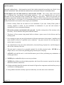
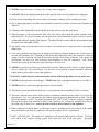
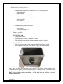
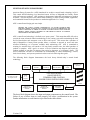
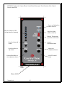
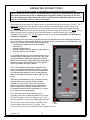
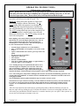
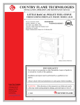
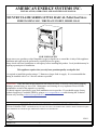
AMERICAN ENERGY SYSTEMS INC.
INSTALLATION, OPERATION AND MAINTENANCE MANUAL
COUNTRY FLAME SERIES LITTLE RASCAL Pellet Fuel Stove
FREESTANDING LEG / FIREPLACE INSERT, MODEL LR-01
FOR YOUR SAFETY
Do not store or use gasoline or other flammables (vapor or liquids) in or around the vicinity of this appliance.
Installation and repair must be performed by a qualified service agency.
Always check with local jurisdiction or code agency before installing this product. Local jurisdiction may be
requiring a permit prior to installation.
This appliance requires that you only burn premium quality wood pellet fuel
It is required to install this product using a 3” diameter or larger fresh air supply. It is recommended that
venting be installed with a 3 to 5 foot rise whenever possible.
WARNING: If the directions in this manual are not followed exactly, a fire may result causing property
damage, personal injury or loss of life. Maintenance and cleaning are very important. Please read the
maintenance section of this manual very carefully.
Technical support is provided by your local installation service provider. If you should require factory
technical support it is available FREE by going to www.magnumheat.com and selecting the Technical
Forum or by emailing [email protected].
TESTED BY: WARNOCK HERSEY – MOBILE HOME APPROVED
USA & CANADA TEST: ASTM E1509-04, UL 1482, ULC S627, ULC/ORD C1482 (and ULC S628 if listed for fireplace
insert Installation in Canada) Oregon Administrative Rules 814-23-900 thru 909
©2011
Version 1.0c
1
LITTLE RASCAL
MODEL LR-01 PELLET FUEL STOVE
TABLE OF CONTENTS
Introduction
Page 3
Safety Notes
Page 4-6
Specifications
Page 7
Operating Instructions
Description
Pre-Operation Notes
Lighting Procedure
Shut System Down
Wiring Diagram
Maintenance
Page 8-15
Page 8
Page 10
Page 16-17
Page 18
Page 19
Page 20-21
Installation Instructions
Precautions
Free Standing Unit
Positioning
Venting
Details
Leg & Pedestal Installation
Insert Unit
Positioning
Venting
Details
Mobile Home Venting Standards
Page 22
Page 23
Page 24-25
Page 26
Page 27-28
Page 29
Page 30
Page 30
Page 31
Plates & Tags
Page 32 -33
Warranty
Page 34-35
LOOK AT THE LABEL ON THE BACK OF YOUR UNIT TO FIND THE SERIAL NUMBER.
WRITE IT HERE _______________ IMMEDIATELY.
Failure to do so will make servicing and maintenance questions difficult to answer and could result in
needless inconvenience in the future. You will need the serial number of your unit if it requires
servicing.
Version 1.0c
2
INTRODUCTION
Congratulations on your purchase of a Country Flame solid fuel heater. Your heater was designed to provide
you with durable, reliable performance and ease of operation.
The Country Flame LR-01 has been painstakingly designed with your comfort in mind. On those cool evenings
when you’d like a little extra heat in the room, but you don’t want to turn on the furnace, you’ll enjoy the
thermal efficiency of the LR-01. Whether you use your unit to heat a single room or several rooms, you’ll
appreciate the speed with which your unit can be lit and brought up to temperature.
You’ll feel that you’ve slipped into the homey comforting glow of yesterday as you warm yourself in front of
your new heater, with all the comforts of a good, solid wood burning stove, but without the bulk and mess of a
conventional heater. While others have to trudge outside to chop wood and gather kindling, you’ll be warming
yourself by the fire, fueled by easy to load pelletized solid fuel. On cold winter nights, your LR-01 will become
a true friend and you’ll wonder how you ever got along without it.
Features:
*Clean Pelletized Solid Fuel System
*HOT 15 Tube Exchanger Design
*Industry Proven Auger System
*Solid Brass Door & Trim Available
*Integrated Control System
*Insert Installation Option
*Freestanding Queen Ann Leg Options
g{tÇ~ çÉâ yÜÉÅ tÄÄ à{x xÅÑÄÉçxxá Éy TÅxÜ|vtÇ XÇxÜzç fçáàxÅá \ÇvA
This is a comprehensive manual – to avoid confusion when installing your stove:
1. Read and familiarize yourself with the Entire Manual and Safety Notes.
2. Follow the Installation Instructions, Precautions, Positioning, Venting, and Details.
3. Follow the Operating Instructions, Lighting, Shutdown and First Time Operation.
Version 1.0c
3
SAFETY NOTES
FOR SAFE OPERATION – THIS MANUAL MUST BE USED FOR INSTALLATION OF STOVE UNIT
AND RETAINED BY THE OWNER FOR OPERATION AND MAINTENANCE INFORMATION.
PLEASE READ ALL OF THIS MANUAL AND SAFETY NOTES. The Country Flame LR-01 Pellet
Stove is different from conventional wood burning appliances. It is very important that you read and
understand all of the instructions before installing and using your Pellet Stove. Follow the procedures and
maintenance instructions outlined in this manual exactly. Failure to follow instructions may result in property
damage, bodily injury, or even death. It is recommended that you have your unit installed by your authorized
Country Flame dealer or at least have them inspect your installation.
1. Because Country Flame has no control over the installation of your unit, Country Flame grants no
warranty, implied or written, for the installation or maintenance of your unit and assumes no
responsibility for any consequential damage.
2. Fill out the warranty card included with your unit. Send the return portion of the warranty card to
the factory. Please retain the other portion with this manual.
3. This heater will not operate using natural draft or without a power source for the blowers and fuel
feeding system.
4. Never attempt to repair any part of the unit unless following instructions in this manual. Installation and
repair should be done by a qualified service technician. Any parts removed for servicing must be
replaced prior to operation.
5. Any modifications to the unit, unless authorized by American Energy Systems Inc, could be dangerous
and void the warranty of the unit.
6. This unit must be connected to a grounded standard 110-volt 60hz electrical outlet. NEVER use an
adapter cord or cut or remove the grounding prong from the power cord plug.
7. ALWAYS wait until the unit is cooled and disconnect power before performing any maintenance or
cleaning procedures.
8. NEVER place combustible objects on or near your heater.
9. NEVER allow children near heater during operation, and do not allow anyone to operate the unit who is
unfamiliar with these instructions.
10. Children and adults should be alerted to the hazards of high surface temperature and should stay away to
avoid burns or clothing ignition.
11. Young children should be carefully supervised when they are in the same room as the heater.
Version 1.0c
4
12. NEVER connect this unit to a chimney flue serving another appliance.
13. ALWAYS follow the lighting instructions in this manual; short cuts of any kind can be dangerous.
14. Check your local building codes and consult your insurance company before installing your unit.
15. Due to high temperatures, the pellet stove should be located out of traffic and away from furniture and
draperies.
16. Clothing or other flammable material should not be placed on or near the room heater.
17. When disposing of ash accumulations from your unit, always place them in a metal container with a
tight fitting lid. The closed container must be placed on a non-combustible surface well away from all
combustible materials, pending final disposal. The ashes should be retained in the closed container until
all cinders have thoroughly cooled.
18. Any safety screen or guard removed for servicing a room heater must be replaced prior to operating the
room heater.
19. Your unit is designed and approved for burning of Premium pelletized biomass fuel, which meets or
exceeds APFI standards only. Burning of solid fuel in other than pellet form is not permitted. Failure to
comply with this restriction will void all warranties and the safety listing of the unit. Poor quality fuel
will directly (and adversely) affect efficiency and cleanliness of your unit’s operation. Your Country
Flame dealer can help you make the proper fuel choice for your area.
20. NEVER use gasoline, gasoline-type lantern fuel, kerosene, charcoal lighter fluid or similar liquids to
start or “freshen up” fire in this heater. Do not store or use gasoline or other flammable vapors and
liquids in the vicinity of this or any other appliance.
21. INSTALL a smoke detector/carbon monoxide detector within the proximity of your pellet stove.
22. NEVER put foreign objects in the hopper. NEVER burn trash or unapproved material in your LR-01.
23. NEVER block free airflow through open vents or fresh air intake.
24. The exhaust system should be checked twice a year (minimum) for any buildup of soot or creosote.
25. This unit’s exhaust system works with a negative combustion chamber pressure and a low positive flue
pipe pressure. It is very important that the exhaust system be properly installed and air tight. The flue
pipe joints should be sealed. Use high temperature RTV (5000F) (2600C) silicone sealant or aluminum
flue tape and secured each joint with at least (3) sheet metal screws. Improperly installed stove flues are
the major cause of home fires. Always provide a fresh air direct connect to the appliance.
26. When installed in a mobile home, a pellet stove must be grounded to the steel chassis of the mobile
home and bolted to the floor in compliance with and according to H.U.D. requirements.
27. SOOT AND FLYASH: The products of combustion will contain small particles of flyash. The flyash
will collect in the exhaust venting system and restrict the flow of the flue gases. Incomplete
Version 1.0c
5
combustion, such as occurs during start-up, shut down, or incorrect operation of the room heater will
lead to some soot formation which will collect in the exhaust venting system. The exhaust venting
system should be inspected at least once every year to determine if cleaning is necessary.
SPECIFICATIONS
FUEL TYPE:
A.P.F.I. residential fuel: Premium quality fuel only
Heat Content: 8200 BTU/lb. min.
Bulk Density: 40 lb. /cubic ft. min.
Moisture Content: 8% max
Ash Content: 1% max
Size: ¼” to 3/8” diameter
1.5” long max
Fines: 1% max through 1/8th screen
HOPPER SIZE:
55pounds Hopper Capacity
FLUE SIZE:
TYPE:
3” or 4”
PL double wall vent with stainless steel inner liner
AIR INLET:
3” diameter (non-combustible) pipe (recommend double walled B-vent for fresh air only)
AUGER TYPE:
Tumac 2 ¼ Auger Pellet Feed System
CONTROLS:
Integrated Feed Rate/Blower Speed Controls
ELECTRICAL:
120 Volts, 2.4 Amp, 60 Hz (always install an approved surge protector)
MEASUREMENTS:
UNIT BODY HEIGHT
HEIGHT ON PEDESTAL
HEIGHT ON LEGS
UNIT WIDTH
UNIT DEPTH
SHROUD HEIGHT
SHROUD WIDTH
22 ¾”
32 ¾”
31 1/4”
26”
19 3/4”
29 7/8”
45 7/8”
CLEARANCES:
SIDES
BACK
TOP TO COMBUSTIBLE
TOP TO CEILING
1”
2”
3”
3”
*Combustible Flooring must be covered with non-combustible material extending 6” (150 mm) from front
of unit and 8” (205 mm) from unit on each side. The floor protection on the sides of the stove only has to
extend to the vertical sidewall(s) if the clearances are less than 8”.
Version 1.0c
6
DESCRIPTION
The LR-01 Wood Pellet Stove is designed to sit on legs as a freestanding unit. The
basic stove unit measures 22 3/4” high by 26” wide and 19 3/4” deep. Centered above
the firebox glass front door is a vent through which room convection air is passed.
The left side of the Little Rascal has a control panel called the control board. The
control board includes 5 heat settings, an ON/OFF switch and lights to indicate the
operational state of the board. The control board monitors and controls all functions of
stove operation. Fine tuning the air flow is controlled by the operator with a damper.
The damper is manually set to obtain optimum burn based on heat setting and local site
conditions. Typically, the air setting will be ½ to 2/3 open all the time.
On the back of the Little Rascal stove is located a 3” tube for installation of outlet
exhaust vent pipe. Also located on the back of the stove is a place to install a 3” inlet
air tube to bring fresh air in from outside the house. DO NOT INSTALL too long a
length of fresh air pipe at 3”. Length and size of fresh air pipe will be determined by
local site specific conditions. Typically do not have over 2 elbows and over 10 feet go
to 4” diameter. The top of the unit lifts up for easy loading of fuel.
1. The Country Flame LR-01 is remarkably simple and safe in its operation. From a
relatively small firebox over 40,000 BTU’s per hour can be produced.
2. The fuel (APFI approved) is loaded into the hopper. After the fire has been lit (see
lighting instructions) an angled drive auger delivers fuel, a few pellets at a time,
into the firepot at a controlled rate. The combustion blower delivers directed air
input, creating a vigorous, efficient burn. The hot exhaust gases are drawn through
a 14-tube heat exchanger, which extracts heat from the gases as they are discharged
to the exhaust pipe.
3. A second blower circulates room air through the heat exchanger, pushing warm air
into the room from the tubes located just above the door. The room air blower is
intended to run continuously and can be easily controlled to maintain a uniform
temperature.
4. The Pellet Stove will deliver a constant amount of heat, which can be varied by
setting the fuel control knob. Besides initial lighting of the unit, the only regular
attention needed will be to fill the 55pounds hopper with fuel; inspection of the
firepot for “clinkering” (see operating instructions) and removal of ash buildup as
required. Typical would be once a day or twice if fuel is lower quality.
AIR DAMPER ADJUSTMENTS
Each LR-01 is shipped with an air damper adjustment. The air damper control is
located on the front of the pellet stove below the hearth lip located directly centered on
the front door. As site specific operating conditions require, such as fuel, altitude, and
customer usage preferences require, there will be a requirement to adjust the air damper
Version 1.0c
7
for more or less combustion air to the unit. To vary the air, the air damper control is
slid in (less air) and out (more air.)
1. Conditions that warrant more combustion air (2/3 to full open) are:
Hardwood pellets
Higher altitudes
Increased heat settings (3- 5)
2. Conditions that warrant less air (1/3 to ½):
Softwood pellets
Low altitudes
Lower heat settings (2-3)
3. Conditions that warrant even less air:
Softwood pellets
Low altitudes
Lower heat settings (1-2)
Things to watch for:
TOO LITTLE AIR
• Extremely lazy flame
• Extremely black and dirty conditions in firebox
• When extended burn on High Settings, too many pellets in firepot
TOO MUCH AIR
• Flame is aggressive but as time progresses, the flame is barely visible
• Fire disappears in burn pot, shown below, or goes out on low settings
Note: Once you have determined the correct air usage for the heat setting and local site
conditions, the air damper control will not need to be adjusted as often. Remember, any
change in site specific conditions will require an adjustment of the air damper.
Don’t be too quick to change air settings. Let the unit burn for an hour or two to
balance the fuel load.
Version 1.0c
8
PRE-OPERATION NOTES
1. Thoroughly read and understand this manual. Pay particular attention to the
maintenance and safety sections of this manual. Failure to inspect the stove and
understand these instructions may cause unsatisfactory performance.
2. Check to see that the intake and exhaust vents are properly tight and correctly
installed.
3. Remove protective materials such as plastic coverings, plastic bags, and other
material shipped with the stove.
4. Insure that the stove is connected to a code approved 120 volt AC power source.
Ensure that the power provided is stable and not varying. If necessary, include a
cost-effective UPS (power source) between the stove and house power to minimize
any problems with the stove. A power surge protector is required for warranty.
5. Open the hopper lid and inspect the hopper before filling with fuel. ENSURE no
foreign objects are left in hopper before loading it with approved pellet fuel.
6. The first time the Country Flame pellet stove is fired up, an odor or smoke may
emanate from the pellet stove. This is normal and should not last very long. Once
the unit is “broken in” (after that first firing) no future odors or smoke should
appear. This may take a few hours, be sure to burn the unit on low settings.
7.
Fuel should conform to A.P.F.I. standards (see page 7).
Premium quality fuel only.
This unit requires
8. Please note: Premium quality labeling does not always mean that the fuel is good.
Check to make sure that the fuel is not old (left over from previous season) and that
the fuel has been kept in climate controlled warehousing. Wet, damp weather will
cause the fuel to soften and crumple in the bag and in the unit. If you find this,
return the fuel to where you purchased it and request good fuel.
Version 1.0c
9
IGNITION/START-UP PROCEDURE
American Energy Systems Inc. (AES) introduced its exclusive control board technology in 2011.
This control board technology was introduced across all lines of MagnuM and Country Flame
pellet and corn stove products. AES continues to demonstrate leadership in bringing new products
to market. AES developed its own control board technology in order to bring reliable, supportable,
and sustainable biomass-fueled products to market throughout the 21st Century.
AES’s control board design goal was simple:
PROVIDE THE LATEST CONTROL METHODOLOGY TO ENSURE MAXIMUM BURN
EFFICIENCY WHILE AUTOMATICALLY CONTROLLING AS MANY ENVIORNMENTAL AND
SYSTEM VARIALBLES IN ORDER TO ENSURE CUSTOMER SATISFACTION WITH THE
PRODUCT WHILE GAINING CONFIDENCE IN THE PRODUCTS ABILITY TO OPERATE
WITH LIMITED CONSUMER EFFORT.
AES’s control board technology is defined as an “open system.” This means that AES will seek to
provide the most advanced controls methodology in the coming years while maintaining the look
and feel that dealers and customers come to know and expect. This means that a purchase of
today’s MagnuM or Country Flame product allows a customer to upgrade to newer and more
advanced technology, as it becomes available while minimizing cost. AES is committed to
ensuring its customer base will remain a life long family member once the initial purchase of
product is complete. AES’s goal is to ensure a service technician can diagnose and repair any
product problem in less than 30 minutes from arrival to departure of a customer’s home. The
service technician will have to demonstrate an understanding of control methodology, sensors,
basic electric theory, and system operation in order to assist in achieving these goals.
The following block diagram demonstrates the basic theory behind today’s control board
technology:
VACUUM
SENSOR
INPUT VOLTAGE
120 Volts AC 60 Hz
15-Ampere Circuit
Fuse
6–9
Amperes
OVERTEMP
SENSOR
FUEL
CONTROL
COMBUSTION
AIR CONTROL
Hopper
Switch
THERMOSTAT
(Optional)
CONTROL BOARD
ON/OFF SWITCH
TEMPERATURE CONTROL
POWER/FUEL/IGNITER/ INDICATORS
STOVE
EXHAUST
TEMPERATURE
SENSOR
ROOM AIR
TEMPERATURE
SENSOR
ROOM AIR
CONTROL
IGNITER
The basic block diagram shows the input and output components to the control board. The
failure of any of these items to work properly will cause a malfunction in the system.
Further information on each function is provided in the tables below.
Version 1.0c
10
Input Voltage
Fuse (fast acting)
Vacuum Sensor
Exhaust Temperature Sensor
Overtemp Sensor
Fuel Control
Room Air Control
Combustion Air Control
Stir Rod
Thermostat (optional)
Version 1.0c
Alternating Current (AC) Input provided by the local power company. This source of energy
must provide a 120 Volt input signal with a frequency of 60 Hertz and a maximum branch
current capacity of 15 Amperes. If other devices are connected to the branch, interference or
over current may cause circuit breaker to trip.
The AC fuse should be rated between 6 and 9 amperes.
Ensures that no blockage of the combustion input or combustion exhaust air occurs. If the
vacuum sensor does not operate properly, the Control Board will not allow the stove to
operate.
Presently, this sensor is a snap disk operating at 110o F +/- 20o F. This sensor ensures proper
exhaust temperature has been reached and that a fire is present in the burn pot before the
control system begins the burn cycle.
Presently, this sensor is a snap disk operating at 250o F +/- 20o F. The purpose of this sensor
is to shut the entire system down in the event the firebox causes an overheat condition.
The fuel control is a signal provided from the Control Board to the Auger Feed Motor. The
Control Board controls the amount of time that the Auger Feed Motor is on and thereby
controls the amount of fuel fed to the fire pot.
The room air control is a signal provided from the Control Board to the Room Air Fan. The
Control Board controls the phase angle and thereby the amount and time an AC voltage is
applied to the Room Air Fan. This signal controls the speed of the room air passing over the
heat exchanger tubes and the amount of heat delivered to the living space.
The combustion air control is a signal provided from the Control Board to the Combustion
Fan. The Control Board controls the phase angle and thereby the amount and time an AC
voltage is applied to the Combustion Air Fan. This signal controls the speed of the
combustion air passing through the burn pot for the different heat settings
An AC device used to create turbulence in the burn pot. The stir rod reduces the potential of
a clinker thereby ensuring more efficient combustion process. The operator must remove and
clean the stir rod from time to time. Be careful not to damage or break the stir rod.
A thermostat input is provided on the back of each Country Flame product. The Control
Board has individual personality modules that allow for stand-alone, semi automatic, or fully
automatic thermostat operation.
11
FIGURE 5 displays the Country Flame Control Board front panel. Each function of the Control
Board is identified.
Power- on light glows
amber when on
Heat level indictor LED
(red per heat level setting)
Auger feed light
(amber when on)
Manual, Thermostatic
operation mode button
Heat level (up) adj.
button
room air
adjustment button
Heat level (down)
adj. button
Auger trim
Adjustment button
Exhaust/Draft Blower
trim adjustment button
ON/OFF control
button
Please NOTE:
Version 1.0c
12
OPERATING INSTRUCTIONS
(Using self igniter systems, if auto ignition system (optional) has been installed)
NOTE: Before the stove is started, the firepot must be checked for debris and clear air holes.
Some fuels will cause the firepot to build up more frequently making it necessary to stir and
clean the firepot more often. Do not allow ash to build up underneath the firepot area or in the
ash pan as it will block off the air flow to the firepot.
Your control panel has three (3) separate modes of operation (switch located on top of board). The
MANUAL setting allows the operator to choose heat level setting changes without a thermostat.
The T-STAT setting allows the operator to set the highest heat level setting desired and when the
thermostat is satisfied, the unit will automatically go to the low heat level setting. The AUTO setting
allows the unit to shut completely off when the thermostat is satisfied and re-start when the
thermostat calls for heat. The AUTO setting can only be used with wood pellets or a 50/50 mix of
corn and wood pellets.
Before lighting your Country Flame for the first time make sure that all items are out of the hopper and firebox
area. Note: If using a wall thermostat, make sure that the thermostat is turned up above room temperature. The
unit will operate on low fire if the thermostat is turned down.
9 Load the hopper with fuel (Corn or Wood Pellets).
9 Close the door
9 Push the “On/Off” button.
9 Turn the air intake butterfly damper to approximately ¼
inch open. (More or less as needed.)
NOTE: Priming the auger is required when the unit is new or
when the hopper has completely run out of fuel. This can be
done approximately 1 minute after pushing the on/off start
button. Press and hold the “auger” button until fuel begins to
drop into the firepot. When fuel begins to drop regularly,
release auger button, the auger is primed.
NOTE: The viewing door, ash pan door and hopper door
must be closed and/or latched during operation or vacuum
will not be established. If vacuum can not be established the
stove will shut down and the #2 heat level setting light will
blink. The ON/OFF button must be held for app. 6 seconds
to reset.
The unit starts automatically on a pre-set heat level setting.
After the unit has been turned on, and the 1 minute
diagnostics has run, you may select a desired heat level.
However, the heat level feed rate will not change until the
unit has completed the 15 minute startup sequence. It is
recommended to burn the unit on the number #2 or #3 heat
level setting for the first 30-45 minutes.
If the fire temperature has not reached proper
operating temperature within the minimum cycle time
(15 min.) the auger will stop feeding, the stove will
shut down and the #3 heat level setting light will blink.
You will need to press and hold the ON/OFF button
for 6 seconds to start the cycle over again. If the
system is set on auto start it will attempt two startups on its own.
Version 1.0c
13
The draft and room air blower speed varies with each feed rate. The “Draft Trim” button will
override the variable fan function +/- 5 volts on all heat levels. To override, press and hold the
“Draft Trim” button along with the heat level button arrow up or heat level button arrow down,
depending on desired change.
The auger feed rate on each setting is pre-programmed but may be changed if necessary. The
“Auger Trim” button will override the programmed feed rates by +/-5% on all heat levels. To
override the feed rate press and hold the ‘Auger Trim’ button along with the heat level button arrow
up or heat level button arrow down, depending on desired change.
NOTE: In case of a power outage or interruption lasting longer than 5 seconds, the “On/Off”
button must be pushed and held for app. 6 seconds to re-engage the auger. If needed re-light
the unit.
NOTE: If the fire is burning too fast and the fuel is being burned up too quickly, turn the air intake butterfly damper
closed a little to slow the fire down. This should be done in small 1/4” increments so that the fire doesn’t change too
quickly. You can also adjust the draft or auger trim to balance out the burn rate.
NOTE: When changing the heat levels there will be a delay so the system can complete the
cycle before switching to the new heat level.
NOTE: In case of a power outage, the pressure switch has tripped, the door has been opened,
the hopper door has been left open or any power interruption lasting longer than 5 seconds,
the “On/Off” button must be pushed and held for app. 6 seconds (or until you here a click) to
re-engage the auger system.
IMPORTANT: The circuit board will not function properly if the outlet is not a constant 120
volt, 60 cycle power source. The outlet must be grounded properly and have the correct
polarity. A polarity and ground tester can be picked up at any hardware store to assure
proper operation. If you are using a power generator, solar power or wind generation make
sure that you have a constant correct power source.
The unit’s electrical warranty would become void if a constant power source is not available.
Also make sure that a proper surge protector is between the unit and the power source. The
circuit board will not be warranted if there is not a surge protector installed to the unit.
It is strongly recommended that you unplug the power source during times when the unit is
not being operated to protect the unit from power surges, power spikes and drops in power. It
is very common for a circuit board to work when the unit is shut off in the spring and then
won’t work in the fall. Unplugging the unit will prevent this from happening.
Version 1.0c
14
OPERATING INSTRUCTIONS
(Without using system igniter)
NOTE: Before the stove is started, the firepot should be checked for debris and clear air holes.
Some fuels will cause the firepot to build up more frequently making it necessary to stir and
clean the firepot more often. Do not allow ash to build up underneath the firepot.
Your control panel has three (3) separate modes of
operation (switch located on top of board). The
MANUAL setting allows the operator to choose heat
level setting changes without a thermostat. The TSTAT setting allows the operator to set the high heat
level setting and when the thermostat is satisfied, the
unit will automatically go to the low heat level setting.
The AUTO setting allows the unit to shut completely off
when the thermostat is satisfied and re-start when the
thermostat calls for heat. The AUTO setting can only be
used with wood pellets.
Before lighting your Country Flame for the first time make sure
that all items are out of the hopper and firebox area. Note: If
using a wall thermostat, make sure that the thermostat is
turned up above room temperature. The unit will operate on
low fire if the thermostat is turned down.
9
9
9
9
9
9
9
Load the hopper with fuel (Corn or Wood Pellets).
Place a small handful of wood pellets or fire starter in the
firepot.
Squirt a small amount of fire starter gel on top of the wood
pellets.
(Evenly across the wood pellets)
Light the fire starter gel.
Close the door
Push the “On/Off” button.
Turn the air intake butterfly damper to approximately ¼
inch open. (More or less as needed.)
NOTE: Priming the auger is required when the unit is new or
when the hopper has completely run out of fuel. This can be
done approximately 1 minute after pushing the on/off start
button. Press and hold the “auger” button until fuel begins to
drop into the firepot. When fuel begins to drop regularly, release auger button, the auger is primed.
NOTE: The viewing door, ash pan door and hopper door must be closed and/or latched during operation or the
vacuum will not be established. If vacuum can not be established the stove will shut down and the #2 heat level
setting light will blink.
The ON/OFF button must be pushed and held for app. 6 seconds to reset the system.
The unit starts on a pre-set heat level setting. After the unit has been turned on you may select the desired heat
level. However, the feed rate heat level will not change until the unit has completed the 15 minute startup
sequence. It is recommended to burn the unit on the number #2 or #3 heat level setting for the first 30-45
minutes.
If the fire temperature has not reached proper operating temperature within the minimum cycle time (15
min.) the auger will stop feeding, the stove will shut down and the #3 heat level setting light will blink. You
will need to press and hold the ON/OFF button for 6 seconds to start the cycle over again. If the system is set
on auto start it will attempt two startups on its own.
Version 1.0c
15
The draft and room air blower speed varies directly with the feed rate. The “Draft Trim” button will override
the variable fan function +/- 5 volts on all heat levels. To override, press and hold the “Draft Trim” button
along with the heat level button arrow up or heat level button arrow down, depending on desired change.
The auger feed rate on each setting is pre-programmed but may be changed if necessary. The “Auger Trim”
button will override the programmed feed rates by +/-5% on all heat levels. To override the feed rate press
and hold the ‘Auger Trim’ button along with the heat level button arrow up or heat level button arrow down,
depending on desired change.
NOTE: In case of a power outage or interruption lasting longer than 5 seconds, the “On/Off” button
must be pushed to re-engage the auger. If needed re-light the unit.
NOTE: If the fire is burning too fast and the fuel is being burned up too quickly, turn the air intake butterfly damper
closed a little to slow the fire down. This should be done in small 1/4” increments so that the fire doesn’t change too
quickly. You may also adjust the draft and auger trim to balance the burn rate.
NOTE: When changing the heat levels there will be a delay so the system can complete the cycle before switching to the
new heat level.
NOTE: In case of a power outage, the pressure switch has tripped, the door has been opened, the
hopper door has been left open or any power interruption lasting longer than 5 seconds, the “On/Off”
button must be pushed and held for app. 6 seconds (or until you here a click) to re-engage the auger
system.
IMPORTANT: The circuit board will not function properly if the outlet is not a constant 120 volt, 60
cycle power source. The outlet must be grounded properly and have the correct polarity. A polarity
and ground tester can be picked up at any hardware store to assure proper operation. If you are using
a power generator, solar power or wind generation make sure that you have a constant correct power
source.
The unit’s electrical warranty would become void if a constant power source is not available. Also
make sure that a proper surge protector is between the unit and the power source. The circuit board
will not be warranted if there is not a surge protector installed to the unit.
It is strongly recommended that you unplug the power source during times when the unit is not being
operated to protect the unit from power surges, power spikes and drops in power. It is very common
for a circuit board to work when the unit is shut off in the spring and then won’t work in the fall.
Unplugging the unit will prevent this from happening.
Before starting the Country Flame Biomass unit again, it is important to remember to clean out the
firepot, empty the ashes, clean out the heat exchangers, vacuum out the hopper if needed and fill the
hopper with fuel.
Basic Circuit Board Functions (expanded)/Diagnostics Operation
The ON/OFF button initiates the start of the circuit board and the shut down
of the board. Pushing the ON/OFF button momentarily will engage the start
up sequence. The ON/OFF button also is used to re-set the board when the
vacuum switch or proof of fire switch is tripped. Pushing the ON/OFF
button until the board re-sets (usually 6-7 seconds) will re-establish the
system and the fire will continue unless there is a failure in the electrical
components.
When you push the ON/OFF button to start the unit, power light will be on
and the start up sequence will take approx. 12-15 min. During the start up
sequence, the fuel level setting will be over ridden and the unit will feed at
the pre-set fuel rate setting. After the start up sequence has been established
(approx. 12-15 min.) the unit will run at whatever fuel level setting you
Version 1.0c
16
selected. The number #2 or #3 heat level setting is recommended for the 1st 30-45 minutes.
The auger light will flash when the auger is running. On the wood setting the auger will start right away. If on
the corn setting there is a (2) minute delay prior to starting. You can hold the auger button down to override
the system and manually prime the auger.
The room fan button will override the # 1 heat level setting fan speed and go to high speed. This will not
change the fan speed on the #2 - #5 heat level settings.
The auger trim button allows for a low/high fuel setting fine tune adjustment on the all 5 settings. When
pushing the auger trim button select either the heat level up button or heat level down button depending on the
fine tune requirements.
The draft trim allows for a low/high setting fan speed and go to a lower or
higher setting depending on requirements. When pushing the draft trim
button select either the heat level up button or the heat level down button
to fine tune fan speed.
The heat level setting button is a manual heat adjustment. Pushing the
heat level setting button will advance the heat settings one level each time
that it is pushed. The LED light will show which heat level setting the
unit is on. At start up, regardless of where the heat level setting button is
set, the unit will feed on the pre-set heat level setting. Once the start up
sequence has been established, the fuel feed rate setting will run at
whatever fuel level setting you selected.
During a short power outage, the board will detect if the proof of fire
switch is engaged. If it is still engaged (closed) the unit will auto re-start.
Shutdown
To shut the unit down, simply press the On/Off button. The room fan
and exhaust blower will continue to operate until the low limit/cool
down sensor tells it that the fire is out. At that point the exhaust fan
will continue to run for an additional 15 minutes to make sure there
is no exhaust in stove.
Your control panel comes with the ability to use ten (10) separate programming features. This programming
must be done by a qualified factory trained technician. Contact your local dealer to set up an appointment to
have this done. The unit also has three (3) separate modes of operation (switch located on top of board). The
manual setting allows the operator to choose heat level setting changes. The T-STAT setting allows the
operator to set the high heat level setting and when the thermostat is satisfied, the unit will automatically go to
the low heat level setting. The AUTO setting allows the unit to shut completely off when the thermostat is
satisfied and re-start when the thermostat calls for heat. This setting can only be used with wood pellets.
Version 1.0c
17
AC MODEL WIRING DIAGRAM
WARNING: DISCONNECT POWER BEFORE SERVICING THIS UNIT.
Version 1.0c
18
MAINTENANCE
1. If pellets contain a large amount of “fines” (foreign matter or sawdust), you will need to clean
the heat exchanger area for buildup often to determine if any maintenance is needed. You may
want to screen pellets before use if they contain a large number of “fines.”
2. Sand in the pellets may cause “clinkering” (hard brittle deposits found in the bottom of the
firepot). Clinkering is primarily caused by fuel impurities, but it may be intensified if the stove
is run for a long time with a low amount of fuel. A full load of fuel allows less cool air to enter
the burnpot as pellets drop in.
3. A clinker may be removed with a spoon and dropped into the ash pan. NOTE: For your
safety, only remove clinkers from stove when unit is cool. When the stove is cold, the firepot
can be pulled out and removed for a thorough cleaning.
4. SOOT AND FLYASH: the products of combustion will contain small particles of flyash. The
flyash will collect in the exhaust venting system and restrict the flow of the flue gases.
Incomplete combustion, such as occurs during start-up, shut down, or incorrect operation of the
room heater will lead to some soot formation which will collect in the exhaust venting system.
The exhaust venting system should be inspected at least once every year to determine if
cleaning is necessary.
5. The frequency of cleaning your unit will depend on the particular installation, fuel and usage of
your unit. You will know your stove needs cleaning either by inspection or by a marked
decrease in performance. We suggest you check your unit often, especially during its “breakin” period.
6. Shut off the power to the unit and allow it to cool off when performing cleaning and
maintenance.
7. The exhaust vent should be checked frequently, at least once a season and cleaned at least once
a season.
8. Check to insure that the fresh air intake is clear and unobstructed, especially at the start of the
season.
9. The Heat Exchanger has a simple cleaning feature. A sliding plate is fit over the fifteen tubes
of the exchanger. The sliding plate is attached to a small rod protruding through the front of
the stove just below the louver vent. Push the rod to the back of the exchanger and then pull
forward to the front, several times. This will effectively remove ash and debris from the
surface of the heat exchanger. Performing this step often will insure that cleaning is an easy
task. If buildup is allowed to go unattended, cleanup will be much more difficult and the
efficiency of your stove will be adversely affected.
Version 1.0c
Page 19
10. Remove the ash pan using either the ash pan removal tool (furnished) or a glove. Lift the ash
pan up and out the door. Dump the ash pan into a fire safe, covered container. The firepot
may be lifted out and dumped using a glove. With these items removed, carefully check that
the unit and all ashes are cooled completely. Vacuum out the bottom of the unit, paying close
attention to the air inlet. Vacuum the inside of the unit thoroughly cleaning the 2 holes found
under the ash pan. Replace all parts once cleaning is completed. This cleaning should be done
monthly or as needed to insure proper operation. An annual cleaning should be
accomplished by a certified professional to ensure proper performance.
11. Depending on usage, both the room air & exhaust blowers may need to be cleaned once a year
by vacuuming off the motor and impeller. This simple step will greatly increase the life and
serviceability of your unit.
12. To clean glass, use a mild non-abrasive cleaner when cool. Speedy White is an excellent glass
and stove cleaner. Creosote builds up on glass quickly when fire is burned at lowest settings.
DO NOT use abrasive cleaners on glass. Periodically clean out the door air wash (a groove at
the bottom of the door). This air wash directs air over the glass door to minimize soot buildup
on the door.
13. Once a year it is advisable to inspect the door gasket. This is done by taking a 2” strip of paper
and shutting the door on it. Then pull the paper to test the gasket pressure. You should have to
pull the paper from the door. Check all around the gasket. If the paper slides out easily or falls
out, the gasket needs to be replaced. We recommend that both the door and glass gasket be
replaced at the same time.
To replace the gaskets, remove the door by lifting it straight up, off of its hinge pins and lay
face down on a soft surface. Remove door gasketing (you may need to use pliers). Remove
glass retaining clips and remove glass. Strip off old gasketing around glass and clean glass
well. Clean out old stove gasketing material from gasket track.
Once the door and glass are clean, apply gasketing material to glass surface and return glass to
door, securing with clips (Use care not to over tighten). Then apply a generous bead of
gasketing cement into the track. Position the new gasket into the window frame. Gently press
this gasket into the door to ensure proper “seating.” Trim off any excess gasketing and wipe
away excess cement. Let the cement set 24 hours before placing door back on unit. Gasket
material and cement may be obtained from your dealer.
14. Replacement glass should be 0.200” (5mm) thick. Overall size of the glass is 16” (405mm)
wide by 11” (279mm) high, cut to an irregular shape to fit the door front. Your unit uses
ceramic type high temp glass. Do not use any other glass type in this unit. Replacement glass
may be obtained from a Country Flame Dealer or online at www.magnumheat.com.
15. Use care not to slam or strike the door as this could result in glass breakage. If the glass in a
pellet stove is broken or cracked, DO NOT operate the unit until the ceramic glass has been
replaced.
Version 1.0c
Page 20
Maintenance Cont.
It is important that the combustion air intake area is kept clean and free from a buildup of ash. Once a
week, remove the ash pan and firepot out of the firebox area and clean out the built-up ash using an
approved ash vacuum. Using a small cleanout hose (available with ash vac kit), suck the ash out of the
air intake and inside of the firebox area so that air can flow easily.
If ash gets way back in the air channels it will restrict air flow and cause the unit to burn dirty and the
firepot will overflow with un-burnt fuel.
Clean the area around the igniter tube and carefully clean the end of the igniter of any buildup.
When installing the firepot to its original position, make sure that the firepot is seating down into
position and there are no gaps in the bottom of the firepot cradle to the bottom of the unit. If the
firepot is not seated properly air will leak and the fire will burn dirty and fuel will build up in the
firepot area.
Version 1.0c
Page 21
INSTALLATION / PRECAUTIONS
IMPORTANT:
Read all instructions carefully before starting installation. Failure to
follow these installation instructions may result in a possible fire hazard
and will void the Country Flame warranty.
1. Look at the label on the back of your unit to find the serial number. Write the serial
number of the unit on the Table of Contents page immediately. Failure to do so will make
servicing and maintenance questions difficult to answer and could result in needless
inconvenience in the future. You will need the serial number of your unit if it requires
servicing.
2. When installing appliance
A. When installing heater as an insert or as a freestanding unit, adequate clearances
must be strictly adhered to.
B. Allow for adequate accessibility for servicing and proper operations.
C. When establishing clearances, measure from any combustible projection, such as;
shelves, windowsills, fireplace mantles above the appliance, etc.
D. Proper vent installation is required for safe, reliable operation.
manufacturers instructions closely.
Follow vent
WARNING:
OPERATION OF THIS HEATER WHEN NOT CONNECTED TO A
PROPERLY INSTALLED AND MAINTAINED FLUE VENTING SYSTEM IS DANGEROUS.
•
DO NOT INSTALL A FLUE DAMPER IN THE EXHAUST VENTING SYSTEM OF THIS
UNIT.
•
DO NOT CONNECT THIS UNIT TO A CHIMNEY FLUE SERVING ANOTHER
APPLIANCE.
•
MAINTAIN VENT PIPE CLEARANCES AS SPECIFIED BY THE VENT PIPE
MANUFACTURER.
•
IT IS REQUIRED TO PROVIDE A 3” MINIMUM FRESH AIR CONNECTION TO THE
APPLIANCE FROM OUTSIDE OF THE HOME.
PROPER DESIGN AND
INSTALLATION IS REQUIRED.
•
IT IS RECOMMENDED FOR SAFE OPERATION OF THE APPLIANCE THAT YOU
HAVE A QUALIFIED HVAC CONTRACTOR DETERMINE IF YOUR HOME HAS ANY
NEGATIVE PRESSURE PROBLEMS. NEGATIVE PRESSURE WITHIN THE HOME IS
DANGEROUS AND WILL CAUSE HEALTH AND SAFETY PROBLEMS. YOUR
APPLIANCE WILL NOT BURN CORRECTLY IF YOUR HOME HAS THESE ISSUES.
Version 1.0c
Page 22
INSTALLATION / FREESTANDING UNIT / POSITIONING
1. When determining the proper location for your unit, keep in mind the heater should be kept out
of any traffic paths in the room, away from curtains, drapes or any other combustibles. It
should also be placed in a position where heat will be evenly distributed throughout the room.
2. When location has been determined, position the unit within the clearance parameters shown
below.
3. MINIMUM CLEARANCES: The following diagram provides minimum clearances for the
Little Rascal installation based on whether single or double-wall flue pipe and connectors are
used.
C
Dim A, B, C = 1”
Side Wall
Side Wall
Ceiling
TOP
3”
E
D
A
B
4. If installing a pellet stove on carpet, linoleum or other combustible material, a floor protector is
required. It should be at least 42” wide and 30 ½” deep and placed directly under the pellet
stove. This floor protection must be made of metal or some other non-combustible material,
such as ceramic tile or brick.
5. Verify that the location for a pellet stove does not interfere or block airflow. The Little Rascal
draws air from the side grills on the left and right doors.
6. WARNING: ALL combustibles in front of a LR-01 must be kept a minimum of at least 48”
(120cm) from the unit. Remember that combustible vapors can travel a long distance.
7. A combustible mantel may be located no closer than 6” (150cm) to the top of a freestanding
heater.
Version 1.0c
Page 23
INSTALLATION / FREESTANDING UNIT / VENTING
1. After positioning the Little Rascal in its final position, proper flue venting must be installed
according to local and national codes. The LR-01 is a rear vented unit and flue vent pipe can
be run directly from the rear of the unit. Proper venting can be achieved by installing 3” TYPE
PL double wall vent pipe according to code requirements. Country Flame requires the use of
4” flue vent pipe if lengths of ten feet or greater are to be used in a specific installation. Pellet
flue pipe manufacturers’ instructions should be consulted for detailed installation instructions
of their product.
These same manufacturers provide detailed drawings of venting
configurations, which meet or exceed code requirements. This information is available from
hearth dealers or can be downloaded from specific websites.
FOLLOW ALL VENT MANUFACTURER’S VENTING INSTRUCTIONS.
INSTALLATION DRAWINGS ARE FOR ILLUSTRATION PURPOSES ONLY.
WARNING: Operation of the Little Rascal Model LR-01 is dangerous when not connected to a
properly installed; code approved, and maintained flue pipe and fresh air intake system.
2. The venting of this unit should NOT be connected to a flue serving another appliance.
3. At least a 3” clearance is required from all combustibles to the vent pipe, when using required
TYPE PL double wall vent pipe with stainless steel liner. This includes the area(s) where the
pipe passes through the roof. This clearance is generally met by installing flashing in roofs and
fire stop spacers between floors and ceilings. A thimble is needed for through wall
applications. Do not install a flue damper in this system.
4. Install the vent pipe directly onto the vent adaptor on the back of the unit. Be sure to push
firmly into position. Each flue pipe joint needs to be joined tightly with at least (3) sheet metal
screws and sealed with RTV silicone or aluminum flue tape. Air tight venting is required of
each flue pipe joint.
NOTE: IT IS REQUIRED (ESPECIALLY IN MOBILE HOMES), THAT INSTALLATIONS
USE OUTSIDE COMBUSTION AIR FOR THE PELLET STOVE. IF ROOM AIR IS USED
FOR FRESH COMBUSTION AIR, YOU MAY HAVE PROBLEMS WITH NEGATIVE
PRESSURE WITHIN THE HOME CAUSING SERIOUS COMBUSTION ISSUES.
5. When using outside air, the metal rigid or flexible inlet pipe should have a mesh screen to
prevent rodents or birds blocking the pipe, also an elbow or shield should be used to prevent
prevailing winds from blowing directly into the air intake. For best efficiency, locate air inlet
24” (607mm) or more from exhaust vent pipe.
6. The LR-01 is designed to accept installations using a horizontal vent through an exterior wall.
A horizontal flue pipe installation should be a minimum of 24” from pellet stove vent pipe to
flue cap connection. FIGURE 1 shows a through the wall exterior vent installation.
Version 1.0c
Page 24
EXTERIOR WALL
EXTERIOR WALL
JET CAP
WALL THIMBLE
FLUE PIPE
FLUE PIPE
CLEAN OUT "T"
JET CAP
FIGURE 1: HORIZONTAL VENT PIPE (2 options)
7. FIGURE 2 shows a traditional, as well as more efficient, flue pipe installation. Note the
dimensions that are required to be maintained in this type of installation. Dimensions are A
equals a minimum of 24”, B equals a minimum of 3”, and C equals a minimum of 6”. Again,
check with the flue pipe manufacturer’s installation instructions and code requirements for
exact specifications. DIMENSIONS:
FIGURE 2: TRADITIONAL VENT PIPE
Version 1.0c
Page 25
8. For installations that pass through a vertical wall and not through the roof, Country Flame
recommends an installation similar to the one shown in FIGURE 3. Dimension A should be a
minimum of 16” and dimension B should be a minimum of 3”. Any outside vent should have a
vertical run of at least 5’. At the same time, ensure that termination of the flue pipe does not
occur just under the roof overhang. Such a termination can cause smoke to seep back through
the roof and into the home. For all flue pipe runs over 5’, there should be a flue support no less
than 5’ apart.
EXTERIOR WALL
JET CAP
FLUE PIPE
CLEAN OUT "T"
FIGURE 3: RECOMMENDED EXTERIOR WALL INSTALLATION
All installations MUST include a fresh air combustion pipe at least 3” diameter. Such a pipe can be
rigid metal, or flexible metal pipe. In newer homes, it is strongly recommended that an exterior fresh
air combustion vent be installed to ensure proper amounts of air are provided to the pellet stoves
combustion chamber.
Version 1.0c
Page 26
INSTALLATION / FREESTANDING UNIT / DETAIL
The flue vent exit shall be located not less than 48” from any opening through which exhaust could
enter the building, (i.e. windows and doors), and not less than 24” from adjacent public walkways. It
shall be arranged so that flue gases are not directed in such a way as to pose a health hazard, overheat
combustible structures or enter any building. Do not terminate the exhaust flue pipe in an attic,
garage, carport or any enclosed or semi-enclosed area, under a porch or sun deck, or near shrubs or
combustibles stored near the outlet.
Exhaust Vent
Pipe
FIGURE 4: EXTERIOR MINIMUM CLEARANCES
FROM VENT EXIT TERMINAL
TO DOORS, WINDOW, OPENINGS
____________________________________________________________________________________________________
____________________________________________________________________________________________________
____________________________________________________________________________________________________
____________________________________________________________________________________________________
BG
Version 1.0c
HORIZONTAL: 48”
BELOW OPENINGS: 48
ABOVE OPENINGS: 12
ADJACENT WALKWAYS: 24”
Page 27
INSTALLATION / FREESTANDING UNIT / DETAILS
LEG INSTALLATION / FREESTANDING UNIT / DETAILS
1. Locate the eight (8) bolts in the package that comes with the leg kit.
2. Bolt the four (4) legs to the bottom of the pellet stove using two bolts per leg for a total of eight
(8) bolts through the holes provided at the bottom corner of each unit.
3. Use the leveling bolts provided to level the pellet stove. The pellet stove should be level or
slightly declined from front to back. If this is not done, “bridging of pellets” may occur
once the stove is operated.
FIGURE 5: LEG INSTALLATION
PEDESTAL INSTALLATION
1. The pedestal is designed to be mounted to the bottom of the Little Rascal using the for corner
leg hole mounts. There is a wing on each side pf the pedestal for bolts to go through.
2. Position the pedestal and attach it with the four (4) bolts provided.
FIGURE 6: PEDESTAL INSTALLATION
Version 1.0c
Page 28
INSTALLATION / INSERT UNIT / POSITIONING
1. The LR-01 insert is designed to be inserted into an existing masonry fireplace or zero clearance
box. The suitability of the existing firebox needs to be determined. You should insure that the
heater is kept out of any traffic paths in the room, away from curtains, drapes or any other
combustibles. You should also check that the existing fireplace was placed in a position where
heat will be evenly distributed throughout the room.
2. If the existing fireplace is found to be suitable, the LR-01 may be installed using zero
clearance.
3. While installing the LR-01, verify that the location will not interfere with the circulation
airflow. The unit draws air from the grills on both sides of the unit.
4. The heater should be installed in such a manner so that the front of the unit remains unblocked.
This will allow for needed service and maintenance to the unit, and provide access to the
firepot cleanout.
Mantel or Combustible
CLEARANCES FOR INSERT:
B
Side Wall
DIMENSIONS:
A = 3”
B = 6”
C = 6”
A
INSERT
Hearth Extension
FIGURE 7: INSERT MINIMUM CLEARANCES
Version 1.0c
Page 29
C
INSTALLATION / INSERT UNIT / VENTING
1. The LR-01 is designed for both new installations and as an insert into existing fireplaces. The
LR-01 is NOT designed to be installed without proper vent pipe. Proper venting can be
achieved by installing a 3” (less than ten feet) or 4” (more than ten feet) TYPE PL double wall
vent pipe or listed TYPE “L” chimney liner. A listed single wall stainless steel liner may be
used if installing the LR-01 into an approved wood burning chimney. The vent pipe may be run
to the top of the existing chimney or to a point 18” above the damper of the existing chimney.
Flue pipe manufacturer’s instructions should be consulted for further detailed pipe installation
instructions. Most flue pipe manufacturers will provide detailed drawings of venting plans,
which meet or exceed code requirements. NOTE: Follow all vent manufacturers vent pipe
instructions without deviation. Check local codes to ensure conformance.
2. WARNING: DO NOT operate any pellet stove unless connected to proper flue system. Do
not connect the LR-01 to a chimney flue serving another appliance.
3. Flue pipe joints need to be joined tightly to ensure air tight venting with at least (3) sheet metal
screws and sealed with RTV silicone or approved aluminum flue pipe tape.
4. FIGURE 8 shows a sample of a Country Flame recommended method of flue pipe installation.
The vent pipe is extended just above the top of the existing chimney (consult local ordinances
for code requirements.) The flue pipe must be fitted with a proper pellet flue cap. A storm
collar and flashing should be installed to seal off the chimney opening.
FIGURE 8: CHIMNEY FLUE AND FRESH AIR VENTING
Version 1.0c
Page 30
INSTALLATION / MOBILE HOME STANDARDS
1. Mobile home code requires the pellet stove be bolted to the floor regardless of whether it has
legs or is mounted on its optional pedestal.
2. A pellet stove must be electrically grounded to the steel frame of the mobile home.
3. A pellet stove must have an outside combustion air source installed in a mobile home.
4. CAUTION: THE STRUCTURAL INTEGRITY OF THE MOBILE HOME (floors, walls,
ceilings and roof) MUST BE MAINTAINED.
5. WARNING: DO NOT INSTALL A PELLET STOVE IN A SLEEPING AREA.
6. Check any other local building codes as they apply.
BOLT
LEGS TO
FLOOR
FIGURE 11: MOBILE HOME LEG INSTALLATION
BOLT PEDESTAL
TO FLOOR
FIGURE 12: MOBILE HOME PEDESTAL INSTALLATION
Version 1.0c
Page 31
HEATER COMPONENTS: PLATES AND TAGS
A safety label is shown in FIGURE 14 for informational purposes. Refer to the back of a LR-01 pellet
stove for the actual safety label. Illustrations are artist renderings and the actual label on a product
may vary slightly in information and design.
1. Each LR-01 has a serial number fixed to the certification label attached to the back of the unit.
Record the serial number in the owner’s manual for future reference.
Version 1.0c
Page 32
2. A label on the back of the unit warns that the stove is hot. See the safety section of your
owner’s manual for more safe operating tips.
3. Information and warning labels are located under the hopper lid. These labels provide
information on operation and maintenance that the operator should always follow when
operating the stove. Keep the hopper lid closed during operation.
4. There are electrical warning labels inside the LR-01 that inform the consumer that before any
electrical service is attempted on a unit, disconnect the unit from the source power before
servicing. Also, the warning labels inform the consumer that the unit should not be run with
covers removed.
Version 1.0c
Page 33
AMERICAN ENERGY SYSTEMS INC. LIMITED PRODUCT
WARRANTY
This warranty is in effect on all products sold after 01/01/2009 and supersedes any and all warranties currently in
existence.
Please keep a copy of this warranty for your personal records or in the event of a claim
American Energy Systems Inc., hereinafter referred to as (AES), warrants to you, the original consumer purchaser, that this
product is free from defects in material and workmanship for a period of five (5) years from the original purchase date minus
any time past one (1) year from manufacturing date, and that the product’s electrical parts and steel firepot, are free from
defects in material and workmanship for a period of one (1) year from the original consumer purchase date minus any time
past one (1) year from manufacturing date, and that the cast iron firepot models carry a lifetime warranty against defect in
material or workmanship (excluding war page or deterioration), and that door glass carries a lifetime replacement warranty
against heat breakage (does not cover accidental breakage) . There is expressly no warranty on installation of product, any
venting, grates, gaskets, door latches, insulation, ceramic or brick boards/logs/backing, paint, plated surfaces/doors/trims,
baffles, bushings, bearings, auger flightings, war page or discoloration of steel or plated parts or any other normal wearing
part. In the event the product fails to conform to this warranty, AES, through the place where you purchased the product or if
purchased on the AES E-Com store directly through AES, will provide the parts and components necessary to remedy such
nonconformity. AES will not be responsible for any labor, mileage or freight cost to the factory under this warranty.
This warranty is not transferable.
In order to obtain performance under this warranty, you must (1) have registered this warranty within 30 days of purchase by
completing and returning the warranty registration card or filling in the on-line warranty registration form at
www.magnumheat.com, and (2) promptly report the claimed nonconformity to your place of purchase, also providing your
name, address, phone number, proof of purchase, date of purchase, the model and serial number of the stove, digital pictures
of installation and venting inside and outside of the home, pictures of the claimed nonconformity part and the claimed
nonconformity. All claims must be submitted in writing to your place of purchase.
AES shall have no warranty obligations if this product; (1) was not purchased from an authorized AES dealer; (2) was not
installed by a AES dealer or other qualified installer; does not have outside combustion air hooked directly to the unit; (3)
was not operated and maintained in strict accordance with the manufacturer’s instructions, local or national codes or (4) was
subject to abuse, misuse, negligence or accident. AES shall have no warranty obligation for damage caused by improper
handling, freight damage (must be reported to freight provider), over-firing, unapproved fuel, variance in feed rates, variances
in BTU output or the unauthorized disassembly or modification of the product. AES shall have no warranty obligation if this
warranty is not timely registered, for claims which are not submitted through the selling AES dealer, or for claims submitted
verbally or without the required information and documentation.
Before exercising this warranty, an AES representative (the place where the product was purchased or AES approved person)
must inspect the part/unit to determine if the part/unit is defective. If a local AES representative is not available the original
purchaser of the product must submit digital pictures of the part/unit, installation of the unit to AES at
[email protected] If the inspection reveals that the failure is due to defective material or workmanship and the
part is covered by the conditions of this warranty, AES will, at its option, repair the defective part/unit. The sole duty of AES
and liability under this warranty is limited to the repair of the covered defective part/unit. The purchaser shall assume all
costs related to shipping the replacement parts or return of the unit to the factory for repairs. If it is determined that the defect
was caused by AES, AES will cover the costs of shipping the repaired part/unit to an AES approved shipping point. AES
will not cover additional freight or delivery services such as residence delivery charges, special handling, etc.
INSTALLATION, VENTING, REMOVAL OR REINSTALLATION COSTS ARE NOT COVERED BY THIS
WARRANTY.
THE WARRANTY PRINTED ABOVE IS THE ONLY WARRANTY APPLICABLE TO THE PRODUCT.
ALL OTHER WARRANTIES, EXPRESSED OR IMPLIED, INCLUDING, WITHOUT LIMITATION, THE
IMPLIED WARRANTIES OF MERCHANTABILITY AND FITNESS FOR A PARTICULAR PURPOSE, ARE
DISCLAIMED.
IT IS UNDERSTOOD AND AGREED THAT AES’S LIABILITY UNDER THIS
WARRANTY SHALL BE LIMITED TO THE PROVISION OF REPLACEMENT PARTS AND SHALL NOT
INCLUDE LIABILITY FOR SPECIAL, INCIDENTAL OR CONSEQUENTIAL DAMAGES. ANY ACTION
BROUGHT UNDER THIS WARRANTY MUST BE BROUGHT WITHIN ONE YEAR OF THE ACCRUAL
OF THE CAUSE OF ACTION AND MAY ONLY BE BROUGHT IN THE CIRCUIT COURT OF MCCLOUD
COUNTY, MINNESOTA.
Some states do not allow limitations on how long an implied warranty lasts or the exclusion or limitation of incidental or consequential
damage, so the above limitations may not apply to you. This warranty gives you specific legal rights, and you may also have other rights
which vary from state to state.
ALL WARRANTY CLAIMS MUST BE SUBMITTED IN WRITING THROUGH THE PLACE WHERE THE PRODUCT
WAS PURCHASED. In the event where the place of purchase has ceased business or if you feel that there is a legitimate
reason that you cannot submit your claim to the place where the product was purchased you may make a written request to
the factory by emailing your request along with all of the required information to [email protected] . NOTE:
Verbal requests will not be recognized. If it is determined that warranty could have been performed by the place of
purchase, the factory will deny the claim.
Included with the claim must be the following information: (if this information is not complete, the claim will be denied)
Name, address, telephone number, email address, of place of business where product was purchased & also
purchaser contact info.
Date of purchase, model and serial number of product, digital pictures of product (front, sides, back, venting inside
and outside)
(If there is ductwork, there must be digital pictures of entire ductwork installation, static pressures, air flow
measurements, and contact information of licensed/factory certified contractor that installed unit)
Nature of defect, what has been serviced (service record), who installed product along with contact information
Place
Stamp
Here
American Energy Systems, Inc
150 Michigan Street SE
Hutchinson, MN 55350
Fold Here
Name
Address
City
State
Zip
Dealer
Dealer’s Name
City
State
Zip
Date of Purchase
Model No.
Serial Number
Email address:___________________________________________
Telephone number:_________________________________________
The express warranties made by American Energy Systems Inc. do not apply unless this card is returned to Country
Flame Technologies by the original retail purchaser no later than thirty (30) days from date of retail purchase.
Signature
Date