1
About This Guide
This section discusses the objectives, audience, organization, and conventions of this
hardware installation and configuration guide.
Objectives
This publication will step you through the initial site preparation and installation of the
router. Troubleshooting, maintenance procedures, and cable specifications are also
provided.
Although minimum software configuration information is provided, it is not meant as
comprehensive router configuration instructions. For detailed software configuration
information, refer to the Cisco IOS configuration guide and command reference
publications. These publications are available on the documentation CD that came with
your router or you can order printed copies. Refer to the “Ordering Documentation” section
in the “Overview of the Router” chapter for ordering information.
This publication describes a variety of router models that are similar in functionality, but
differ in the number of interfaces supported. Some information provided may not apply to
your particular router model.
Audience
This publication is designed for the person installing the router, who should be familiar with
electronic circuitry and wiring practices and have experience as an electronic or
electromechanical technician.
About This Guide xv
Organization
Organization
The major sections of this hardware installation and configuration guide are as follows:
•
Chapter 1, “Overview of the Router,” discusses the features and specifications of the
routers, and describes how to obtain technical support and order documentation.
•
Chapter 2, “Preparing to Install the Router,” discusses environmental requirements,
safety recommendations, and describes the various ports and how to prepare for
connections between networks and ports.
•
Chapter 3, “Installing the Router,” includes basic installation information and discusses
making connections to your LAN, WAN, and console terminal.
•
Chapter 4, “Configuring the Router,” discusses how to configure your router using the
prompt-driven System Configuration Dialog, configuration mode, or AutoInstall. This
chapter also provides some basic information about how to use the Cisco IOS software.
•
Appendix A, “Troubleshooting the Router,” discusses how to isolate problems and read
the LEDs.
•
•
Appendix B, “Maintaining the Router,” discusses selected maintenance procedures.
Appendix C, “Cable Specifications,” provides pinouts for the router ports and cables.
Conventions
This publication uses the following conventions to convey instructions and information.
Command descriptions use these conventions:
•
•
•
•
Commands and keywords are in boldface font.
Variables for which you supply values are in italic font.
Elements in square brackets ([ ]) are optional.
Alternative but required keywords are grouped in braces ({ }) and are separated by
vertical bars ( | ).
xvi Router Installation and Configuration Guide
Conventions
Examples use these conventions:
•
•
•
•
Terminal sessions and information the system displays are in screen font.
Information you enter is in boldface
screen
font.
Nonprinting characters are in angle brackets (< >).
Default responses to system prompts are in square brackets ([ ]).
Note Means reader take note. Notes contain helpful suggestions or references to materials
not contained in this manual.
Timesaver Means the described action saves time. You can save time by performing the
action described in the paragraph.
Caution Means reader be careful. In this situation, you might do something that could
result in equipment damage or loss of data.
Warning This warning symbol means danger. You are in a situation that could cause
bodily injury. Before you work on any equipment, you must be aware of the hazards
involved with electrical circuitry and familiar with standard practices for preventing
accidents. (To see translated versions of this warning, refer to the Regulatory Compliance
and Safety Information document that accompanied your router.)
About This Guide xvii
Conventions
xviii Router Installation and Configuration Guide
C H A PT E R
1
Overview of the Router
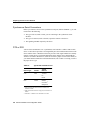
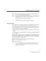
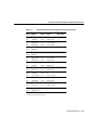
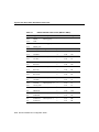
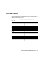
Table 1-1 lists the router models discussed in this publication and provides a summary of
the interfaces supported on each model. These router models are similar in functionality,
but differ in the number of interfaces supported.
Table 1-1
Summary of Router Interfaces
Model
Ethernet
AUI1 (DB-15)
Token Ring
(DB-9)
Serial
(DB-60)
ISDN2 BRI3
(RJ-45)
Cisco 2501/
CPA2501
1
–
2
–
Cisco 2502/
CPA2502
–
1
2
–
Cisco 2503/
CPA2503
1
–
2
1
Cisco 2504/
CPA2504
–
1
2
1
Cisco 2513/
CPA2513
1
1
2
–
Cisco 2514/
CPA2514
2
–
2
–
Cisco 25154
–
2
2
–
1. AUI = attachment unit interface.
2. ISDN = Integrated Services Digital Network.
3. BRI = Basic Rate Interface.
4. A CPA2515 model is not available.
Overview of the Router 1-1
Hardware Features
Note Throughout the remainder of the publication, one model number will be used in text
references. For example, references to the model 2501 router will apply to both the
Cisco 2501 and CPA2501 routers.
Hardware Features
In addition to the interfaces listed in Table 1-1, the routers include the following hardware
features:
•
•
•
•
•
Dynamic random-access memory (DRAM) for main memory and shared memory
Nonvolatile random-access memory (NVRAM) for storing configuration information
Flash memory for running the Cisco IOS software
EIA/TIA-232 console port for local system access using a console terminal
EIA/TIA-232 auxiliary port for remote system access using a modem
Note EIA/TIA-232 and EIA/TIA-449 were known as recommended standards RS-232
and RS-449 before their acceptance as standards by the Electronic Industries Association
(EIA) and Telecommunications Industry Association (TIA).
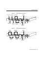
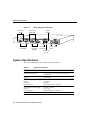
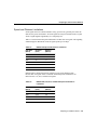
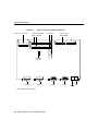
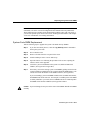
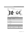
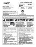
Figure 1-1 to Figure 1-7 show the rear panels of the router models discussed in this
publication.
1-2 Router Installation and Configuration Guide
Hardware Features
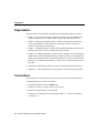
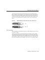
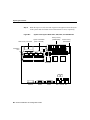
Figure 1-1
Model 2501 Router Rear Panel
Synchronous
serial LEDs
System
OK LED
H4262
Ethernet
AUI LED
Ethernet
AUI port
(DB-15)
Synchronous
serial ports
(DB-60)
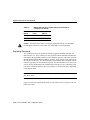
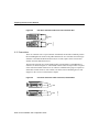
Figure 1-2
On/off
switch
Power
Auxiliary port
(RJ-45)
Model 2502 Router Rear Panel
Synchronous
serial LEDs
System
OK LED
H6585
Token Ring
LED
Console
port (RJ-45)
Token Ring
port (DB-9)
Synchronous
serial ports
(DB-60)
Console
port (RJ-45)
On/off Power
switch
Auxiliary port
(RJ-45)
Overview of the Router 1-3
Hardware Features
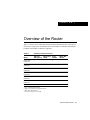
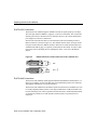
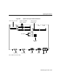
Figure 1-3
Model 2503 Router Rear Panel
Synchronous
serial LEDs
System
OK LED
ISDN
BRI LED
H6586
Ethernet
AUI LED
Ethernet
AUI port
(DB-15)
Synchronous
serial ports
(DB-60)
Figure 1-4
ISDN
BRI port
(RJ-45)
On/off Power
switch
Auxiliary port
(RJ-45)
Model 2504 Router Rear Panel
Synchronous
serial LEDs
System
ISDN
BRI LED OK LED
H6587
Token Ring
LED
Console
port
(RJ-45)
Token Ring
port (DB-9)
Synchronous
serial ports
(DB-60)
Console
port
(RJ-45)
ISDN
BRI port
(RJ-45)
1-4 Router Installation and Configuration Guide
On/off Power
switch
Auxiliary port
(RJ-45)
Hardware Features
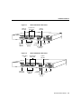
Figure 1-5
Token Ring
LED
Ethernet
AUI LED
Model 2513 Router Rear Panel
System
OK LED
Synchronous
serial LEDs
Token Ring
port (DB-9)
H6588
TOKEN RING
Ethernet
AUI port
(DB-15)
Figure 1-6
Model 2514 Router Rear Panel
System
OK LED
Synchronous
serial LEDs
H6589
Ethernet
AUI LEDs
Synchronous Console port
On/off Power
serial ports
switch
(RJ-45)
(DB-60)
Auxiliary port
(RJ-45)
Ethernet
AUI ports
(DB-15)
Synchronous
serial ports
(DB-60)
Console
port (RJ-45)
On/off Power
switch
Auxiliary port
(RJ-45)
Overview of the Router 1-5
System Specifications
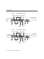
Figure 1-7
Token Ring
LEDs
Model 2515 Router Rear Panel
Synchronous
serial LEDs
H6590
System
OK LED
Token Ring
ports (DB-9)
Synchronous
serial ports
(DB-60)
Console
port (RJ-45)
On/off Power
switch
Auxiliary port
(RJ-45)
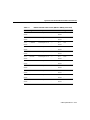
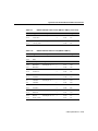
System Specifications
The system specifications of the routers are listed in Table 1-2.
Table 1-2
System Specifications
Description
Specification
Dimensions (H x W x D)
1.75 x 17.5 x 10.56 in. (4.44 x 44.45 x 26.82 cm),
one rack unit
Weight
10 lb (4.5 kg)
Input voltage, AC power supply
Current
Frequency
Power dissipation
100 to 240 VAC
1.2 to 0.6A
50/60 Hz
40W (maximum), 135.5 Btus1/hr
Input voltage, DC power supply
Current
Power dissipation
40W, 40 to 72 VDC
1.5 to 1.0A
40W (maximum), 135.5 Btus/hr
Processor
20-MHz Motorola 68EC030
1-6 Router Installation and Configuration Guide
Obtaining Service and Support
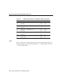
Table 1-2
System Specifications (Continued)
Description
Specification
Interfaces
See Table 1-1 for a list of interfaces supported on each
router model.
• Ethernet AUI (IEEE2 802.3) (DB-15)
• Token Ring (IEEE 802.5) (DB-9)
• Synchronous serial3 (DB-60)
• ISDN BRI (RJ-45)4
• Console (RJ-45)
• Auxiliary (RJ-45)
Operating environment
32 to 104°F (0 to 40°C)
Nonoperating temperature
–40 to 185°F (–40 to 85°C)
Operating humidity
5 to 95%, noncondensing
Noise level
34 dBa @ 3 ft (0.914 m)
Regulatory compliance
FCC Class A and Canadian DOC Class A
For more regulatory information, refer to the
Regulatory Compliance and Safety Information
document that accompanied your router.
1. Btus = British thermal units.
2. IEEE = Institute of Electrical and Electronic Engineers.
3. The synchronous serial interface supports the following standards in data terminal equipment (DTE) and
data communications equipment (DCE) mode: EIA/TIA-232, EIA/TIA-449, V.35, and X.21. The
EIA-530 standard is supported in DTE mode only.
4. External network terminal 1 (NT1) device required.
Obtaining Service and Support
For service and support for a product purchased from a reseller, contact the reseller.
Resellers offer a wide variety of Cisco service and support programs, which are described
in the information packet that shipped with your chassis.
Overview of the Router 1-7
Cisco Connection Online
Note If you purchased your product from a reseller, you can access Cisco Connection
Online (CCO) as a guest. CCO is Cisco Systems’ primary, real-time support channel.Your
reseller offers programs that include direct access to CCO’s services.
For service and support for a product purchased directly from Cisco, use CCO.
Cisco Connection Online
CCO is Cisco Systems’ primary, real-time support channel. SMARTnet customers and
partners can self-register on CCO to obtain additional content and services.
Available 24 hours a day, 7 days a week, CCO provides a wealth of standard and
value-added services to Cisco’s customers and business partners. CCO services include
product information, software updates, release notes, technical tips, the Bug Navigator,
configuration notes, brochures, descriptions of service offerings, and download access to
public and authorized files.
CCO serves a wide variety of users through two interfaces that are updated and enhanced
simultaneously—a character-based version and a multimedia version that resides on the
World Wide Web (WWW). The character-based CCO supports Zmodem, Kermit,
Xmodem, FTP, and Internet e-mail, and is excellent for quick access to information over
lower bandwidths. The WWW version of CCO provides richly formatted documents with
photographs, figures, graphics, and video, as well as hyperlinks to related information.
You can access CCO in the following ways:
•
•
•
•
•
WWW: http://www.cisco.com.
WWW: http://www-europe.cisco.com.
WWW: http://www-china.cisco.com.
Telnet: cco.cisco.com.
Modem: From North America, 408 526-8070; from Europe, 33 1 64 46 40 82. Use the
following terminal settings: VT100 emulation; databits: 8; parity: none; stop bits: 1; and
baud rates up to 14.4 kbps.
1-8 Router Installation and Configuration Guide
Ordering Documentation
For a copy of CCO’s Frequently Asked Questions (FAQ), contact [email protected]. For
additional information, contact [email protected].
Note If you need technical assistance with a Cisco product that is under warranty or
covered by a Cisco maintenance contract, contact Cisco’s Technical Assistance Center
(TAC) at 800 553-2447, 408 526-7209, or [email protected].
Please use CCO to obtain general information about Cisco Systems, Cisco products, or
upgrades. If CCO is not accessible, contact 800 553-6387, 408 526-7208, or
[email protected].
Ordering Documentation
Documentation for Cisco products is available in three forms: on a CD-ROM, printed
books, and on the World Wide Web. You have the option of subscribing to the
documentation CD through an update service. Or you can order printed documentation at
an additional cost. Refer to the information packet included with the router for detailed
ordering information. You can also access Cisco documentation on the World Wide Web
URL http://www.cisco.com.
Overview of the Router 1-9
Ordering Documentation
1-10 Router Installation and Configuration Guide
C H A PT E R
2
Preparing to Install the Router
This chapter describes important information to consider before you begin to install the
router, and includes the following sections:
•
•
•
•
Safety Recommendations
General Site Requirements
Preparing to Connect to a Network
Where to Go Next
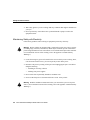
Safety Recommendations
Follow these guidelines to ensure general safety:
•
•
•
•
Keep the chassis area clear and dust-free during and after installation.
•
Wear safety glasses if you are working under any conditions that might be hazardous to
your eyes.
•
Do not perform any action that creates a potential hazard to people or makes the
equipment unsafe.
Put the removed chassis cover in a safe place.
Keep tools away from walk areas where you and others could fall over them.
Do not wear loose clothing that could get caught in the chassis. Fasten your tie or scarf
and roll up your sleeves.
Preparing to Install the Router 2-1
Safety Recommendations
Warning Ultimate disposal of this product should be handled according to all national
laws and regulations. (To see translated versions of this warning, refer to the Regulatory
Compliance and Safety Information document that accompanied your router.)
Maintaining Safety with Electricity
Follow these guidelines when working on equipment powered by electricity.
Warning Before working on equipment that is connected to power lines, remove jewelry
(including rings, necklaces, and watches). Metal objects will heat up when connected to
power and ground and can cause serious burns or can weld the metal object to the terminals.
(To see translated versions of this warning, refer to the Regulatory Compliance and Safety
Information document that accompanied your router.)
•
Locate the emergency power OFF switch for the room in which you are working. Then,
if an electrical accident occurs, you can act quickly to turn OFF the power.
•
Power OFF the router and unplug the power cord before doing the following:
— Installing or removing a chassis
— Working near power supplies
Warning Before working on a chassis or working near power supplies, unplug the power
cord on AC units; disconnect the power at the circuit breaker on DC units. (To see translated
versions of this warning, refer to the Regulatory Compliance and Safety Information
document that accompanied your router.)
Warning Do not touch the power supply when the power cord is connected. For systems
with a power switch, line voltages are present within the power supply even when the power
switch is OFF and the power cord is connected. For systems without a power switch, line
voltages are present within the power supply when the power cord is connected. (To see
translated versions of this warning, refer to the Regulatory Compliance and Safety
Information document that accompanied your router.)
2-2 Router Installation and Configuration Guide
Safety Recommendations
•
•
Do not work alone if potentially hazardous conditions exist.
Never assume that power is disconnected from a circuit. Always check.
Warning Read the installation instructions before you connect the system to its power
source. (To see translated versions of this warning, refer to the Regulatory Compliance and
Safety Information document that accompanied your router.)
•
Look carefully for possible hazards in your work area, such as moist floors, ungrounded
power extension cables, frayed power cords, and missing safety grounds.
•
If an electrical accident occurs, proceed as follows:
— Use caution; do not become a victim yourself.
— Turn OFF power to the system.
— If possible, send another person to get medical aid. Otherwise, assess the condition
of the victim and then call for help.
— Determine if the person needs rescue breathing or external cardiac compressions;
then take appropriate action.
Preventing Electrostatic Discharge Damage
Electrostatic discharge (ESD) can damage equipment and impair electrical circuitry. It
occurs when electronic components are improperly handled and can result in complete or
intermittent failures.
Always follow ESD-prevention procedures when removing and replacing components.
Ensure that the chassis is electrically connected to earth ground. Wear an ESD-preventive
wrist strap, ensuring that it makes good skin contact. Connect the clip to an unpainted
surface of the chassis frame to safely channel unwanted ESD voltages to ground. To
properly guard against ESD damage and shocks, the wrist strap and cord must operate
effectively. If no wrist strap is available, ground yourself by touching the metal part of the
chassis.
Preparing to Install the Router 2-3
General Site Requirements
Caution For safety, periodically check the resistance value of the antistatic strap, which
should be between 1 to 10 megohms (Mohms).
General Site Requirements
This section describes the requirements your site must meet for safe installation and
operation of your system. Ensure that your site is properly prepared before beginning
installation.
Site Environment
The router can be placed on a desktop or mounted in a rack or on a wall. The location of
the chassis and the layout of your equipment rack or wiring room are extremely important
for proper system operation. Equipment placed too close together, inadequate ventilation,
and inaccessible panels can cause system malfunctions and shutdowns, and can make
system maintenance difficult.
When planning your site layout and equipment locations, remember the precautions
described in the next section, “Preventive Site Configuration” to help avoid equipment
failures and reduce the possibility of environmentally caused shutdowns. If you are
experiencing shutdowns or unusually high errors with your existing equipment, these
precautions may help you isolate the cause of failures and prevent future problems.
Preventive Site Configuration
The following precautions will help you plan an acceptable operating environment for your
router and will help you avoid environmentally caused equipment failures.
•
Electrical equipment generates heat. Ambient air temperature might not be adequate to
cool equipment to acceptable operating temperatures without adequate circulation.
Ensure that the room in which you operate your system has adequate air circulation.
•
Always follow the ESD-prevention procedures described in the section “Preventing
Electrostatic Discharge Damage” earlier in this chapter to avoid damage to equipment.
Damage from static discharge can cause immediate or intermittent equipment failure.
2-4 Router Installation and Configuration Guide
General Site Requirements
•
Ensure that the chassis cover is secure. The chassis is designed to allow cooling air to
flow effectively within it. An open chassis allows air leaks, which may interrupt and
redirect the flow of cooling air from internal components.
Configuring Equipment Racks
The following information will help you plan an acceptable equipment rack configuration.
•
Enclosed racks must have adequate ventilation. Ensure that the rack is not overly
congested because each unit generates heat. An enclosed rack should have louvered
sides and a fan to provide cooling air.
•
When mounting a chassis in an open rack, ensure that the rack frame does not block the
intake or the exhaust ports. If the chassis is installed on slides, check the position of the
chassis when it is seated all the way into the rack.
•
In an enclosed rack with a ventilation fan in the top, excessive heat generated by
equipment near the bottom of the rack can be drawn upward and into the intake ports of
the equipment above it in the rack. Ensure that you provide adequate ventilation for
equipment at the bottom of the rack.
•
Baffles can help to isolate exhaust air from intake air, which also helps to draw cooling
air through the chassis. The best placement of the baffles depends on the airflow patterns
in the rack, which are found by experimenting with different arrangements.
Power Supply Considerations
Check the power at your site to ensure that you are receiving “clean” power (free of spikes
and noise). Install a power conditioner if necessary.
Warning The device is designed to work with TN power systems. (To see translated
versions of this warning, refer to the Regulatory Compliance and Safety Information
document that accompanied your router.)
Preparing to Install the Router 2-5
Preparing to Connect to a Network
The router power supply includes the following features:
•
•
Autoselects either 110V or 220V operation.
All units include a 6-foot (1.8-meter) electrical power cord. (A label near the power cord
indicates the correct voltage, frequency, current draw, and power dissipation for the
unit.)
Warning This product relies on the building’s installation for short-circuit (overcurrent)
protection. Ensure that a fuse or circuit breaker no larger than 120 VAC, 15A U.S.
(240 VAC, 10A international) is used on the phase conductors (all current-carrying
conductors). (To see translated versions of this warning, refer to the Regulatory Compliance
and Safety Information document that accompanied your router.)
Preparing to Connect to a Network
When setting up your router, consider distance limitations and potential electromagnetic
interference (EMI) as defined by the EIA.
Warning The Ethernet, Token Ring, serial, console, and auxiliary ports contain safety
extra-low voltage (SELV) circuits. BRI circuits are treated like telephone-network voltage
(TNV) circuits. Avoid connecting SELV circuits to TNV circuits. (To see translated
versions of this warning, refer to the Regulatory Compliance and Safety Information
document that accompanied your router.)
2-6 Router Installation and Configuration Guide
Preparing to Connect to a Network
ISDN Connections
Use a BRI cable (not included) to connect the router directly to an ISDN. (See Table 2-1.)
Warning Network hazardous voltages are present in the BRI cable. If you detach the BRI
cable, detach the end away from the router first to avoid possible electric shock. Network
hazardous voltages also are present on the system card in the area of the BRI port (RJ-45
connector), regardless of when power is turned OFF. (To see translated versions of this
warning, refer to the Regulatory Compliance and Safety Information document that
accompanied your router.)
Warning The ISDN connection is regarded as a source of voltage that should be
inaccessible to user contact. Do not attempt to tamper with or open any public telephone
operator (PTO)-provided equipment or connection hardware. Any hardwired connection
(other than by a nonremovable, connect-one-time-only plug) must be made only by PTO
staff or suitably trained engineers. (To see translated versions of this warning, refer to the
Regulatory Compliance and Safety Information document that accompanied your router.)
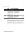
Table 2-1 lists the specifications for ISDN BRI cables. Refer to the section “ISDN BRI Port
and Cable Pinouts” in the appendix “Cable Specifications” for pinouts.
Table 2-1
ISDN BRI Cable Specifications
Specification
High-Capacitance Cable
Low-Capacitance Cable
Resistance (at 96 kHz)
160 ohms/km
160 ohms/km
1/km
Capacitance (at 1 kHz)
120 nF
30 nF/km
Impedance (96 kHz)
75 ohms
150 ohms
Wire diameter
0.024 in. (0.6 mm)
0.024 in. (0.6 mm)
Distance limitation
32.8 ft (10 m)
32.8 ft (10 m)
1. nF = nanoFarad.
Preparing to Install the Router 2-7
Preparing to Connect to a Network
Synchronous Serial Connections
Before you connect a device to the synchronous serial port (labeled “SERIAL”), you will
need to know the following:
•
The type of device, DTE or DCE, you are connecting to the synchronous serial
interface.
•
•
The type of connector, male or female, required to connect to the device.
The signaling standard required by the device.
DTE or DCE
A device that communicates over a synchronous serial interface is either a DTE or DCE
device. A DCE device provides a clock signal that paces the communications between the
device and the router. A DTE device does not provide a clock signal. DTE devices usually
connect to DCE devices. The documentation that came with the device should indicate
whether it is a DTE or DCE device. (Some devices have a jumper to select either mode.) If
you cannot find the information in the documentation, refer to Table 2-2 to help you select
the proper device type.
Table 2-2
Typical DTE and DCE Devices
Device Type
Gender
Typical
Devices
DTE
Male1
Terminal
PC
Router
DCE
Female
2
Modem
CSU/DSU3
Multiplexer
1. If pins protrude from the base of the connector, the
connector is male.
2. If the connector has holes to accept pins, the connector is
female.
3. CSU/DSU = Channel service unit/data service unit.
2-8 Router Installation and Configuration Guide
Preparing to Connect to a Network
Speed and Distance Limitations
Serial signals can travel a limited distance at any given bit rate; generally, the slower the
data rate, the greater the distance. All serial signals are subject to distance limits, beyond
which a signal degrades significantly or is completely lost.
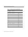
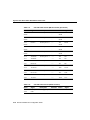
Table 2-3 lists the maximum speeds and distances for EIA/TIA-232 signals. This signaling
standard supports unbalanced circuits at signal speeds up to 64 kbps.
Table 2-3
EIA/TIA-232 Speed and Distance Limitations
Data Rate
(Baud)
Distance
(Feet)
Distance
(Meters)
2400
200
60
4800
100
30
9600
50
15
19200
50
15
38400
50
15
64000
25
7.6
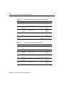
Balanced drivers allow EIA/TIA-449 signals to travel greater distances than
the EIA/TIA-232 signals. Table 2-4 lists the maximum speeds and distances for
EIA/TIA-449, V.35, X.21, and EIA-530 signals.
Table 2-4
EIA/TIA-449, V.35, X.21, and EIA-530 Speed and Distance
Limitations
Data Rate
(Baud)
Distance
(Feet)
Distance
(Meters)
2400
4,100
1,250
4800
2,050
625
9600
1,025
312
19200
513
156
Preparing to Install the Router 2-9
Preparing to Connect to a Network
Table 2-4
EIA/TIA-449, V.35, X.21, and EIA-530 Speed and Distance
Limitations (Continued)
Data Rate
(Baud)
Distance
(Feet)
Distance
(Meters)
38400
256
78
56000
102
31
Caution The EIA/TIA-449 and V.35 interfaces support data rates up to 2.048 Mbps.
Exceeding this maximum could result in loss of data and is not recommended.
Signaling Standards
The synchronous serial port supports the following signaling standards: EIA/TIA-232,
EIA/TIA-449, V.35, X.21, and EIA-530. You can order a DB-60 shielded serial transition
cable that has the appropriate connector for the standard you specify. The router end of the
shielded serial transition cable has a DB-60 connector, which connects to the serial port on
the rear panel of the router. The other end of the serial transition cable is available with the
connector appropriate for the standard you specify. The documentation for the device you
want to connect should indicate the standard used for that device. The synchronous serial
port can be configured as DTE or DCE (except EIA-530, which is DTE only), depending
on the attached cable.
Note All serial ports configured as DTE require external clocking from a CSU/DSU or
other DCE device.
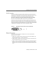
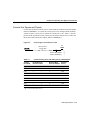
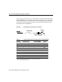
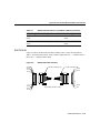
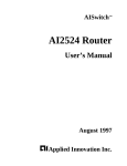
Figure 2-1 shows the serial transition cables you can connect to the serial port on the rear
panel of the router.
2-10 Router Installation and Configuration Guide
Preparing to Connect to a Network
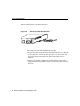
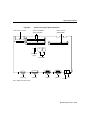
Figure 2-1
Serial Transition Cables
H2485
Router connections
EIA/TIA-232
EIA/TIA-449
V.35
X.21
EIA-530
Network connections at the modem or CSU/DSU
Although attempting to manufacture your own serial cables is not recommended (because
of the small size of the pins on the DB-60 serial connector), cable pinouts are provided in
the appendix “Cable Specifications.” To order a cable, refer to the section “Obtaining
Service and Support” in the “Overview of the Router” chapter.
Preparing to Install the Router 2-11
Preparing to Connect to a Network
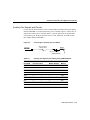
EIA/TIA-232 Connections
The EIA/TIA-232 standard supports unbalanced circuits at signal speeds up to 64 kbps.
The serial port (labeled “SERIAL”) supports synchronous connections. The console and
auxiliary ports also use an EIA/TIA-232 connection; however, the console and auxiliary
ports support asynchronous connections.
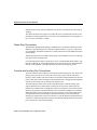
The network end of the EIA/TIA-232 serial transition cable (not included) provides a
DB-25 connector, as shown in Figure 2-2. The end that connects to the serial port on the
rear panel of the router has a DB-60 connector. EIA/TIA-232 serial transition cables are
available with a DB-25 plug or receptacle in either DTE or DCE mode. To order a cable,
refer to the section “Obtaining Service and Support” in the “Overview of the Router”
chapter.
Figure 2-2
EIA/TIA-232 Serial Transition Cable Connectors, Network End
DCE
H1343a
DTE
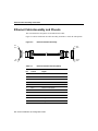
EIA/TIA-449 Connections
The EIA/TIA-449 standard, which supports balanced and unbalanced transmissions, is a
faster (up to 2 Mbps) version of the EIA/TIA-232 standard that provides more functions
and supports transmissions over greater distances.
The EIA/TIA-449 standard was intended to replace the EIA/TIA-232 standard, but it was
not widely adopted primarily because of the large installed base of DB-25 hardware and
because of the larger size of the 37-pin EIA/TIA-449 connectors, which limited the number
of connections possible (fewer than possible with the smaller, 25-pin EIA/TIA-232
connector).
2-12 Router Installation and Configuration Guide
Preparing to Connect to a Network
The network end of the EIA/TIA-449 serial transition cable (not included) provides a
DB-37 connector, as shown in Figure 2-3. The end that connects to the serial port on the
rear panel of the router has a DB-60 connector. EIA/TIA-449 serial transition cables are
available with a DB-37 plug or receptacle in either DTE or DCE mode. To order a cable,
refer to the section “Obtaining Service and Support” in the “Overview of the Router”
chapter.
Figure 2-3
EIA/TIA-449 Serial Transition Cable Connectors, Network End
DCE
H1344a
DTE
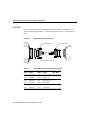
V.35 Connections
The V.35 standard is recommended for speeds up to 48 kbps, although in practice it is used
successfully at 4 Mbps.
The network end of the V.35 serial transition cable (not included) provides a standard
34-pin Winchester-type connector, as shown in Figure 2-4. The end that connects to the
serial port on the rear panel of the router has a DB-60 connector. V.35 cables are available
with a standard V.35 plug or receptacle in either DTE or DCE mode. To order a cable, refer
to the section “Obtaining Service and Support” in the “Overview of the Router” chapter.
Preparing to Install the Router 2-13
Preparing to Connect to a Network
Figure 2-4
V.35 Serial Transition Cable Connectors, Network End
DCE
H1616a
DTE
X.21 Connections
The X.21 connector uses a 15-pin connector for balanced circuits and is commonly used in
the United Kingdom to connect to the public data network. X.21 relocates some of the logic
functions to the DTE and DCE interfaces and, as a result, requires fewer circuits and a
smaller connector than EIA/TIA-232.
The network end of the X.21 serial transition cable (not included) is a standard DB-15
connector, as shown in Figure 2-5. The end that connects to the serial port on the rear panel
of the router has a DB-60 connector. X.21 cables are available with a plug or receptacle in
either DTE or DCE mode. To order a cable, refer to the section “Obtaining Service and
Support” in the “Overview of the Router” chapter.
Figure 2-5
X.21 Serial Transition Cable Connectors, Network End
1
8
15
9
2-14 Router Installation and Configuration Guide
DCE
H1346a
DTE
Preparing to Connect to a Network
EIA-530 Connections
The EIA-530 standard, which supports balanced transmission, provides the increased
functionality, speed, and distance of EIA/TIA-449 on the smaller, DB-25 connector used
for EIA/TIA-232, instead of the 37-pin connector used for EIA/TIA-449. Like
EIA-TIA-449, EIA-530 refers to the electrical specifications of EIA/TIA-422 and
EIA/TIA-423. Although the specification recommends a maximum speed of 2 Mbps,
EIA-530 is used successfully at 4 Mbps or faster speeds over short distances.
The EIA/530 serial transition cable (not included) is available in DTE mode only. The
network end of the EIA-530 adapter cable is a standard DB-25 plug commonly used for
EIA/TIA-232 connections, as shown in Figure 2-6. The end that connects to the serial port
on the rear panel of the router has a DB-60 connector. To order a cable, refer to the section
“Obtaining Service and Support” in the “Overview of the Router” chapter.
EIA-530 Serial Transition Cable Connector, Network End
DTE
H1615a
Figure 2-6
Ethernet Connections
The IEEE has established Ethernet as standard 802.3. The most common Ethernet
implementations are as follows:
•
10Base5 (AUI)—Ethernet on thick coaxial cable, also known as thick Ethernet. The
maximum segment distance is 1,640 feet (500 meters).
•
10Base2 (Thinnet)—Ethernet on thin coaxial cable, also known as thin Ethernet. The
maximum segment distance is 607 feet (185 meters).
•
10BaseT—Ethernet on unshielded twisted-pair (UTP) cable. The maximum segment
distance is 328 feet (100 meters). UTP cables look like the cables used for ordinary
telephones; however, UTP cables meet certain electrical standards that telephone cables
do not.
Preparing to Install the Router 2-15
Preparing to Connect to a Network
Ethernet model routers include an Ethernet AUI interface, which operates at speeds up to
10 Mbps.
The cables and transceivers required to connect the router to an Ethernet network are not
included. For ordering information, refer to the section “Obtaining Service and Support” in
the “Overview of the Router” chapter.
Token Ring Connections
The IEEE has established Token Ring as standard 802.5. The distance limitations for the
IEEE 802.5 specification indicate a maximum segment distance of 328 feet (100 meters)
for UTP cabling. The distance limitation is 1,640 feet (500 meters) for shielded twisted-pair
(STP) cabling.
Token Ring can operate at two different ring speeds: 4 and 16 Mbps. All devices on the ring
must agree on the operating speed.
Use a Token Ring lobe cable to connect the router to a media attachment unit (MAU). The
lobe cable and MAU are not included with the router. Refer to the section “Token Ring Port
Pinouts” in the appendix “Cable Specifications” for the Token Ring port pinouts.
Console and Auxiliary Port Connections
Your router includes an asynchronous serial console and an auxiliary port. The console and
auxiliary ports provide access to the router either locally (with a console terminal) or
remotely (with a modem). This section discusses important cabling information to consider
before connecting a console terminal (an ASCII terminal or PC running terminal emulation
software) to the console port or modem to the auxiliary port.
The main difference between the console and auxiliary ports is that the auxiliary port
supports hardware flow control and the console port does not. Flow control paces the
transmission of data between a sending device and a receiving device. Flow control ensures
that the receiving device can absorb the data sent to it before the sending device sends more.
When the buffers on the receiving device are full, a message is sent to the sending device
to suspend transmission until the data in the buffers has been processed. Because the
auxiliary port supports flow control, it is ideal for use with the high-speed transmissions of
a modem. Console terminals transmit at slower speeds than modems; therefore, the console
port is ideal for use with console terminals.
2-16 Router Installation and Configuration Guide
Where to Go Next
Console Port Connections
Your router includes an EIA/TIA-232 asynchronous serial console port (RJ-45). Cables and
adapters to connect a console terminal (an ASCII terminal or PC running terminal
emulation software) to the console port are included. To connect an ASCII terminal to the
console port, use the RJ-45-to-RJ-45 roll-over cable (looks like a telephone cable) with the
female RJ-45-to-DB-25 adapter (labeled “TERMINAL”). To connect a PC running
terminal emulation software to the console port, use the RJ-45-to-RJ-45 roll-over cable
with the female RJ-45-to-DB-9 adapter (labeled “TERMINAL”). The default parameters
for the console port are 9600 baud, 8 data bits, no parity, and 2 stop bits. The console port
does not support hardware flow control. For detailed information about installing a console
terminal, see the section “Connecting to the Console Port” in the chapter “Installing the
Router.” See the appendix “Cable Specifications” for cable and port pinouts.
Auxiliary Port Connections
Your router includes an EIA/TIA-232 asynchronous serial auxiliary port (RJ-45) that
supports hardware flow control. A cable and an adapter to connect a modem to the auxiliary
port are included. To connect a modem to the auxiliary port, use the RJ-45-to-RJ-45
roll-over cable (looks like a telephone cable) with the male RJ-45-to-DB-25 adapter
(labeled “MODEM”). For detailed information about connecting devices to the auxiliary
port, see the section “Connecting a Modem to the Auxiliary Port” in the chapter “Installing
the Router.” See the appendix “Cable Specifications” for cable and port pinouts.
Where to Go Next
Proceed to the next chapter, “Installing the Router,” for installation instructions.
Preparing to Install the Router 2-17
Where to Go Next
2-18 Router Installation and Configuration Guide
C H A PT E R
3
Installing the Router
This chapter guides you through the installation of the routers and includes the following
sections:
•
•
•
•
•
•
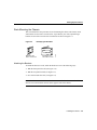
Required Tools and Equipment
Setting Up the Chassis
Connecting the DC Power Supply
Connecting to a Network
Connecting the Console Terminal and Modem
What to Do after Installing the Router Hardware
Warning Only trained and qualified personnel should be allowed to install or replace this
equipment. (To see translated versions of this warning, refer to the Regulatory Compliance
and Safety Information document that accompanied your router.)
Installing the Router 3-1
Required Tools and Equipment
Required Tools and Equipment
Installation requires some tools and equipment that are not provided as standard equipment
with the router. Following are the tools and parts required to install the router:
•
•
•
•
Flat-blade screwdrivers: small, 3/16-inch (0.476 cm) and medium, 1/4-inch (0.625 cm).
ESD-preventive wrist strap.
Screws to secure the rack-mount brackets to the router.
Cables for connection to the WAN and LAN ports:
— Ethernet AUI cable or Ethernet transceiver for connection to the Ethernet AUI port.
— Token Ring lobe cable for connection to the Token Ring port.
— Serial transition cable for connection to the synchronous serial port .
— Cable for connection to the ISDN BRI port.
Note For cable ordering information, refer to the section “Obtaining Service and Support”
in the “Overview of the Router” chapter.
•
Ethernet 10BaseT hub or PC with a network interface card for connection to the
Ethernet AUI (LAN) port.
•
•
•
•
Token Ring MAU for connection to the Token Ring (LAN) port.
•
Modem for connection to the auxiliary port for remote administrative access (optional).
CSU/DSU or other DCE device for connection to the synchronous serial interface.
NT1 device for ISDN BRI WAN connections, if not supplied by your service provider.
Console terminal (an ASCII terminal or a PC running terminal emulation software)
configured for 9600 baud, 8 data bits, no parity, and 2 stop bits. A terminal is required
unless you are using the AutoInstall procedure. See the section “Connecting the
Console Terminal and Modem” later in this chapter for instructions on connecting a
console terminal.
3-2 Router Installation and Configuration Guide
Setting Up the Chassis
Setting Up the Chassis
You can set the chassis on a desktop, install it in a rack, or mount it on a wall or other flat
surface. Use the procedure in this section that best meets the needs of your network. The
sections are as follows:
•
•
•
Setting the Chassis on a Desktop
Rack-Mounting the Chassis
Wall-Mounting the Chassis
Setting the Chassis on a Desktop
Before setting the router on a desktop, shelf, or other flat, secure surface, perform the
following steps to install the rubber feet:
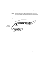
Locate the rubber feet on the black adhesive strip that shipped with the chassis.
(See Figure 3-1.)
Step 1
Figure 3-1
Identifying the Rubber Feet
H4796
Rubber feet (5)
Black adhesive strip
Installing the Router 3-3
Setting Up the Chassis
Step 2
Place the router upside down on a smooth, flat surface.
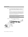
Step 3
Peel off the rubber feet from the black adhesive strip and place them
adhesive-side down onto the five round, recessed areas on the bottom of the
chassis. (See Figure 3-2.)
Figure 3-2
Installing the Rubber Feet
H4795
Fan
Step 4
Place the router right-side up on a flat, smooth, secure surface.
Do not place anything on top of the router that weighs more than 10 pounds
(4.5 kg). Excessive weight on top could damage the chassis.
Caution
3-4 Router Installation and Configuration Guide
Setting Up the Chassis
Rack-Mounting the Chassis
This section describes the procedures for rack-mounting the chassis. The chassis comes
with brackets for use with a 19-inch rack or, if specified in your order, optional larger
brackets for use with a 24-inch rack. The brackets are shown in Figure 3-3.
Bracket for use
with a 19-inch rack
Identifying the Brackets
Bracket for use
with a 24-inch rack
H4201
Figure 3-3
Attaching the Brackets
To install the chassis in a rack, attach the brackets in one of the following ways:
•
•
•
With the front panel forward (see Figure 3-4)
With the rear panel forward (see Figure 3-5)
In a center-mount telco rack (see Figure 3-6)
Note The illustrations that follow show how to connect the bracket to one side of the
chassis. The second bracket connects to the opposite side of the chassis.
Installing the Router 3-5
Setting Up the Chassis
Figure 3-4
Bracket Installation—Front Panel Forward
24 in.
brackets
Figure 3-5
H7821
19 in.
brackets
Bracket Installation—Rear Panel Forward
19 in.
brackets
Figure 3-6
H6329
24 in.
brackets
Telco Bracket Installation—Rear Panel Forward
19 in.
brackets
3-6 Router Installation and Configuration Guide
H6330
24 in.
brackets
Setting Up the Chassis
Installing in a Rack
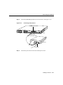
After the brackets are secured to the chassis, you can rack-mount it. Using the screws you
provide, attach the chassis to the rack as shown in Figure 3-7.
Figure 3-7
Attaching the Chassis to a Rack (Rear Panel Forward Shown)
19 in.
brackets
H6331
24 in.
brackets
Wall-Mounting the Chassis
Use the small brackets (for use with a 19-inch rack) to wall-mount the chassis. The small
brackets provide the most stable position for the chassis.
Installing the Router 3-7
Setting Up the Chassis
Take the following steps to wall-mount the chassis:
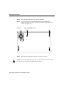
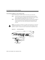
Attach the brackets as shown in Figure 3-8.
Step 1
Figure 3-8
Attaching the Wall-Mount Brackets
Input: 100-240VAC
Freq: 50/60 Hz
Current: 1.2-0.6A
Watts: 40W
H1714
1
0
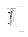
Step 2
Attach the chassis assembly to the wall as shown in Figure 3-9, using screws and
anchors that you provide. We recommend the following:
•
For the best support of the chassis and cables, attach the brackets so that the
screws align with a vertical wall stud. (See Figure 3-9.) This position will
prevent the chassis from pulling away from the wall when cables are
attached.
•
For the best ventilation of the chassis, mount the chassis with the power
supply and fan at the top. Make sure there is clearance between the router and
the wall.
3-8 Router Installation and Configuration Guide
Setting Up the Chassis
Wall-Mounting the Chassis
H6572
TOKEN RING
Figure 3-9
Installing the Router 3-9
Connecting the DC Power Supply
Connecting the DC Power Supply
Some router models offer an optional DC power supply. This section describes the DC
power supply specifications and wiring.
Warning This unit is intended for installation in restricted access areas. A restricted access
area is where access can only be gained by service personnel through the use of a special
tool, lock and key, or other means of security, and is controlled by the authority responsible
for the location. (To see translated versions of the warning, refer to the Regulatory
Compliance and Safety Information document that accompanied your router.)
DC Power Specifications
The DC power supply is intended for use in DC operating environments. Table 3-1 lists the
power supply specifications.
Table 3-1
DC Power Supply Specifications
Description
Design
Specification
Power (input)
40W, –40 to –72 VDC
Wire gauge for power connections
14 AWG1
1. AWG = American Wire Gauge.
3-10 Router Installation and Configuration Guide
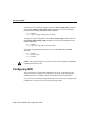
Connecting the DC Power Supply
Wiring the DC Power Supply
If you ordered a router with a DC power supply, follow the directions in this section to wire
the terminal block.
Warning Before performing any of the following procedures, ensure that power is
removed from the DC circuit. To ensure that all power is OFF, locate the circuit breaker on
the panel board that services the DC circuit, switch the circuit breaker to the OFF position,
and tape the switch handle of the circuit breaker in the OFF position. (To see translated
versions of this warning, refer to the Regulatory Compliance and Safety Information
document that accompanied your router.)
Note This product is intended for installation in restricted access areas and is approved for
use with 14 AWG copper conductors only. The installation must comply with all applicable
codes.
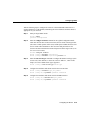
Take the following steps to wire the terminal block:
Step 1
Attach the appropriate lugs at the wire end of the power supply cord.
Step 2
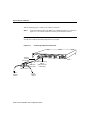
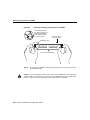
Wire the DC power supply to the terminal block, as shown in Figure 3-10.
Warning The illustration shows the DC power supply terminal block. Wire the DC power
supply using the appropriate lugs at the wiring end, as illustrated. The proper wiring
sequence is ground to ground, positive to positive (line to L), and negative to negative
(neutral to N). Note that the ground wire should always be connected first and disconnected
last. (To see translated versions of this warning, refer to the Regulatory Compliance and
Safety Information document that accompanied your router.)
Installing the Router 3-11
Connecting the DC Power Supply
Figure 3-10
DC Power Supply Connections
Input: –40– –72V
Current: 1.5 –1.0A
Watts: 40W
Terminal block
On/off
switch
Ground
Negative
Positive
H2679
Terminal block
3-12 Router Installation and Configuration Guide
Connecting to a Network
Warning When stranded wiring is required, use approved wiring terminations, such as
closed-loop or spade-type with upturned lugs. These terminations should be the appropriate
size for the wires and should clamp both the insulation and conductor. (To see translated
versions of this warning, refer to the Regulatory Compliance and Safety Information
document that accompanied your router.)
Caution Do not overtorque the terminal block captive thumbscrew or terminal block
contact screws. The recommended torque is 8.2 0.4 inch-lb.
Warning After wiring the DC power supply, remove the tape from the circuit breaker
switch handle and reinstate power by moving the handle of the circuit breaker to the ON
position. (To see translated versions of this warning, refer to the Regulatory Compliance
and Safety Information document that accompanied your router.)
Connecting to a Network
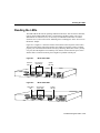
This section explains how to connect the router to your network. The Ethernet or Token
Ring ports are used to connect the router to a LAN. The synchronous serial and ISDN ports
are used to connect the router to a WAN.
The cables required to connect the router to a network are not provided with the router. For
ordering information, refer to the section “Obtaining Service and Support” in the
“Overview of the Router” chapter. For cable pinouts, refer to the appendix “Cable
Specifications.”
Although the illustrations in this section show the model 2513 router, the procedures are
the same for all of the router models.
Warning Do not work on the system or connect or disconnect cables during periods of
lightning activity. (To see translated versions of this warning, refer to the Regulatory
Compliance and Safety Information document that accompanied your router.)
Installing the Router 3-13
Connecting to a Network
Take the following steps to connect your router to a network:
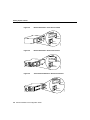
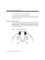
Step 1
Connect the Ethernet AUI port (DB-15) to an Ethernet transceiver, as shown in
Figure 3-11. Or connect a transceiver directly to the Ethernet AUI port.
Note If your Ethernet connection requires jackscrews, remove the slide-latch assembly
from the AUI connector and attach the jackscrews provided.
Connecting an Ethernet Transceiver
H6567
Figure 3-11
TOKEN RING
Ethernet
AUI cable
(not supplied)
Router
Ethernet
transceiver
Ethernet AUI port
(DB-15)
(with jackscrews
or slide-latch)
BNC connector
To thin
Ethernet
network
To thin
Ethernet
network
3-14 Router Installation and Configuration Guide
Connecting to a Network
Connect the Token Ring port (DB-9) to a MAU, as shown in Figure 3-12. To
ensure agency compliance with electromagnetic emissions requirements (EMI),
ensure that the lobe cable is shielded.
Figure 3-12
Connecting a MAU
H6568
Step 2
TOKEN RING
Router
Token Ring
lobe cable
(not provided)
Token Ring
port (DB-9)
MAU
Standard IEEE
802.5 connector
Installing the Router 3-15
Connecting to a Network
Step 3
If you will be using AutoInstall to configure the router, connect the synchronous
serial port (DB-60) to a CSU/DSU or other DCE device, as shown in
Figure 3-13. If you do not plan to use AutoInstall (or you are not sure what
AutoInstall is) do not connect the WAN cable until after you have configured the
router.
If a WAN cable is connected when you power ON the router for the first time, it
will attempt to run AutoInstall to download a configuration file from a TFTP
server. It can take several minutes for the router to determine that the necessary
files are not in place for AutoInstall to begin. For more information about
AutoInstall, refer to the Cisco IOS configuration guide, which is available on the
documentation CD that accompanied your router.
Note The synchronous serial port supports the following signaling standards:
EIA/TIA-232, EIA/TIA-449, V.35, X.21, and EIA-530.
Connecting a CSU/DSU or Other DCE Device
H6569
Figure 3-13
TOKEN RING
Serial transition
cable
Router
Synchronous serial
port (DB-60)
CSU/DSU or
other DCE
EIA/TIA-232, EIA/TIA-449, V.35,
X.21, or EIA-530 connector
3-16 Router Installation and Configuration Guide
Connecting to a Network
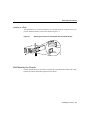
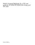
Step 4
Connect the ISDN BRI port (RJ-45) to an NT1 device. (See Figure 3-14.)
Figure 3-14
Connecting an NT1 Device
ISDN BRI port (RJ-45)
SERIAL 4 (A/S)
SERIAL 0
SERIAL 5 (A/S)
SERIAL 1
SERIAL 6 (A/S)
SERIAL 2 (A/S)
SERIAL 7 (A/S)
SERIAL 3 (A/S)
LINK SERIAL 8 (A/S)
ETHERNET 0
AUI
ACT
10bT
BRI 0
Input: 100-240VAC
Freq: 50/60HZ
Current: 1.2-0.6 A
Watts: 40W
PWR
SERIAL 9 (A/S)
CONSOLE
AUX
Router
H6574
Straight-through
RJ-45-to-RJ-45 cable
NT1 device
S/T interface
Step 5
Connect the power cable to the router and the power source.
Installing the Router 3-17
Connecting the Console Terminal and Modem
Connecting the Console Terminal and Modem
Your router includes asynchronous serial console and auxiliary ports. These ports provide
administrative access to your router either locally (with a console terminal) or remotely
(with a modem).
Connecting to the Console Port
Take the following steps to connect a terminal (an ASCII terminal or a PC running terminal
emulation software) to the console port on the router:
Step 1
Connect the terminal using the thin, flat, RJ-45-to-RJ-45 roll-over cable (looks
like a telephone cable) and an RJ-45-to-DB-9 or RJ-45-to-DB-25 adapter
(labeled “TERMINAL”) included with the router. (See Figure 3-15.)
Step 2
Configure your terminal or PC terminal emulation software for 9600 baud,
8 data bits, no parity, and 2 stop bits.
3-18 Router Installation and Configuration Guide
Connecting the Console Terminal and Modem
Figure 3-15
Connecting a Console Terminal
TOKEN RING
Router
Console port
connector (RJ-45)
PC
I/O
card
AUX
H6570
SER 0
OK
LAN
ETH
RJ-45 roll-over cable
RJ-45-to-DB-25 adapter
Installing the Router 3-19
Connecting the Console Terminal and Modem
Connecting a Modem to the Auxiliary Port
Take the following steps to connect a modem to the auxiliary port on the router:
Step 1
Connect a modem to the auxiliary port using the thin, flat, RJ-45-to-RJ-45
roll-over cable (looks like a telephone cable) with the RJ-45-to-DB-25 adapter
(labeled “MODEM”) included with the router. (See Figure 3-16.)
Step 2
Make sure that your modem and the auxiliary port on the router are configured
for the same transmission speed (38400 baud is typical) and hardware flow
control with Data Carrier Detect (DCD) and Data Terminal Ready (DTR)
operations.
Warning This equipment is intended to be grounded. Ensure that the host is connected to
earth ground during normal use. (To see translated versions of this warning, refer to the
Regulatory Compliance and Safety Information document that accompanied the router.)
Connecting a Modem
H6571
Figure 3-16
TOKEN RING
RJ-45
roll-over
cable
Console port
connector (RJ-45)
Modem
RJ-45-to-DB-25 adapter
(EIA/TIA-232)
3-20 Router Installation and Configuration Guide
Failsafe/console
management shelf
What to Do after Installing the Router Hardware
What to Do after Installing the Router Hardware
After you have installed the router, connect the power cable to the rear panel of the router
and the power source and then power it ON. (If the router does not power ON, proceed to
the “Troubleshooting the Router” appendix.)
Proceed to the next chapter, “Configuring the Router,” for initial software configuration
information.
Note The Cisco configuration guide and command reference publications provide
additional software configuration information. These publications are available on the
documentation CD that came with your router or you can order printed copies. Refer to the
section “Ordering Documentation” in the chapter “Overview of the Router” for ordering
information.
Installing the Router 3-21
What to Do after Installing the Router Hardware
3-22 Router Installation and Configuration Guide
C H A PT E R
4
Configuring the Router
This chapter describes how to configure the routers and contains the following sections:
•
•
•
•
•
•
Booting the Router for the First Time
Configuring the Router for the First Time
Cisco IOS Software Basics
Configuring ISDN
Verifying Network Connectivity
Getting More Information
This chapter provides minimum software configuration information; it is not meant as
comprehensive router configuration instructions. Detailed software configuration
information is available in the Cisco IOS configuration guide and command reference
publications. These publications are available on the documentation CD that came with
your router or you can order printed copies. Refer to the section “Ordering Documentation”
in the chapter “Overview of the Router” for ordering information.
Configuring the Router 4-1
Booting the Router for the First Time
Booting the Router for the First Time
Each time you power on the router, it goes through the following boot sequence:
1 The router goes through power-on self-test diagnostics to verify basic operation of the
CPU, memory, and interfaces.
2 The system bootstrap software (boot image) executes and searches for a valid Cisco IOS
image (router operating system software). The source of the Cisco IOS image (Flash
memory or a Trivial File Transfer Protocol [TFTP] server) is determined by the
configuration register setting. The factory-default setting for the configuration register
is 0x2102, which indicates that the router should attempt to load a Cisco IOS image
from Flash memory.
3 If after five attempts a valid Cisco IOS image is not found in Flash memory, the router
reverts to boot ROM mode (which is used to install or upgrade a Cisco IOS image).
4 If a valid Cisco IOS image is found, then the router searches for a valid configuration
file.
5 If a valid configuration file is not found in NVRAM, the router runs the System
Configuration Dialog so you can configure it manually. For normal router operation,
there must be a valid Cisco IOS image in Flash memory and a configuration file in
NVRAM.
The first time you boot your router, you will need to configure the router interfaces and then
save the configuration to a file in NVRAM.
Configuring the Router for the First Time
You can configure the router using one of the following procedures, which are described in
this section:
•
System Configuration Dialog—Recommended if you are not familiar with Cisco IOS
commands.
•
•
Configuration mode—Recommended if you are familiar with Cisco IOS commands.
AutoInstall—Recommended for automatic installation if another router running
Cisco IOS software is installed on the network. This configuration method must be set
up by someone with experience using Cisco IOS software.
4-2 Router Installation and Configuration Guide
Configuring the Router for the First Time
Timesaver Acquire the correct network addresses from your system administrator or
consult your network plan to determine the correct addresses before you begin to configure
the router.
Proceed with the procedure that best fits the needs of your network configuration and
Cisco IOS software experience level. If you will be using configuration mode or
AutoInstall to configure the router, and you would like a quick review of the Cisco IOS
software, refer to the section “Cisco IOS Software Basics” later in this chapter. Otherwise,
proceed with the next section “Using the System Configuration Dialog.”
Using the System Configuration Dialog
If you do not plan to use AutoInstall, make sure all the WAN cables are disconnected from
the router. This will prevent the router from attempting to run the AutoInstall process. The
router will attempt to run AutoInstall whenever you power it ON if there is a WAN
connection on both ends and the router does not have a configuration file stored in
NVRAM. It can take several minutes for the router to determine that AutoInstall is not
connected to a remote TCP/IP host.
If your router does not have a configuration (setup) file and you are not using AutoInstall,
the router will automatically start the setup command facility. An interactive dialog called
the System Configuration Dialog appears on the console screen. This dialog helps you
navigate through the configuration process by prompting you for the configuration
information necessary for the router to operate.
Many prompts in the System Configuration Dialog include default answers, which are
included in square brackets following the question. To accept a default answer, press
Return; otherwise, enter your response.
This section gives an example configuration using the System Configuration Dialog. When
you are configuring your router, respond as appropriate for your network.
At any time during the System Configuration Dialog, you can request help by typing a
question mark (?) at a prompt.
Before proceeding with the System Configuration Dialog, obtain from your system
administrator the node addresses and the number of bits in the subnet field (if applicable)
of the router ports.
Configuring the Router 4-3
Configuring the Router for the First Time
Take the following steps to configure the router using the System Configuration Dialog:
Step 1
Connect a console terminal to the console port on the rear panel of your router,
and then power ON the router. (For more information, refer to the section
“Connecting the Console Terminal and Modem” in the chapter “Installing the
Router.”)
Note The default parameters for the console port are 9600 baud, 8 data bits, no
parity, and 2 stop bits.
After about 30 seconds, information similar to the following is displayed on the
console screen:
Note The messages displayed vary, depending on the interfaces on the rear
panel of the router and the Cisco IOS release and feature set you selected. The
screen displays in this section are for reference only and may not exactly reflect
the screen displays on your console.
System Bootstrap, Version X.X(XXXX) [XXXXX XX], RELEASE SOFTWARE
Copyright (c) 1986-199X by Cisco Systems
2500 processor with 4096 Kbytes of main memory
Notice: NVRAM invalid, possibly due to write erase.
F3: 5797928+162396+258800 at 0x3000060
4-4 Router Installation and Configuration Guide
Configuring the Router for the First Time
Restricted Rights Legend
Use, duplication, or disclosure by the Government is
subject to restrictions as set forth in subparagraph
(c) of the Commercial Computer Software - Restricted
Rights clause at FAR sec. 52.227-19 and subparagraph
(c) (1) (ii) of the Rights in Technical Data and Computer
Software clause at DFARS sec. 252.227-7013.
Cisco Systems, Inc.
170 West Tasman Drive
San Jose, California 95134-1706
Cisco Internetwork Operating System Software
IOS (tm) X000 Software (XXX-X-X), Version XX.X(XXXX) [XXXXX XXX]
Copyright (c) 1986-199X by Cisco Systems, Inc.
Compiled Fri 20-Oct-9X 16:02 by XXXXX
Image text-base: 0x03030FC0, data-base: 0x00001000
Cisco 25XX (68030) processor (revision A) with 4092K/2048K bytes of
memory.
Processor board ID 00000000
Bridging software.
SuperLAT software copyright 1990 by Meridian Technology Corp).
X.25 software, Version X.X, NET2, BFE and GOSIP compliant.
TN3270 Emulation software (copyright 1994 by TGV Inc).
Basic Rate ISDN software, Version X.X.
X Ethernet/IEEE 802.3 interface.
2 Serial network interfaces.
1 ISDN Basic Rate interface.
32K bytes of non-volatile configuration memory.
8192K bytes of processor board System flash (Read ONLY)
Notice: NVRAM invalid, possibly due to write erase.
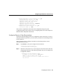
--- System Configuration Dialog --At any point you may enter a question mark '?' for help.
Refer to the 'Getting Started' Guide for additional help.
Use ctrl-c to abort configuration dialog at any prompt.
Default settings are in square brackets '[]'.
Would you like to enter the initial configuration dialog? [yes]:
Configuring the Router 4-5
Configuring the Router for the First Time
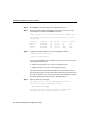
Step 2
Press Return or enter yes to begin the configuration process.
Step 3
When the System Configuration Dialog asks whether you want to view the
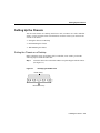
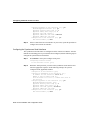
current interface summary, press Return or enter yes:
First, would you like to see the current interface summary? [yes]:
Any interface listed with OK? value “NO” does not have a valid
configuration
Interface
Ethernet0
BRI0
Serial0
Serial1
Step 4
IP-Address
unassigned
unassigned
unassigned
unassigned
OK?
NO
NO
NO
NO
Method
not set
not set
not set
not set
Status
up
up
down
down
Protocol
down
up
down
down
Configure the global parameters. A typical configuration follows:
Configuring global parameters:
Enter host name [Router]:
Next, you are prompted to enter an enable secret password. There are two types
of privileged-level passwords:
•
•
Enable secret password (a very secure, encrypted password)
Enable password (a less secure, nonencrypted password)
The enable password is used when the enable secret password does not exist.
For maximum security, be sure the passwords are different. If you enter the same
password for both, the router will accept your entry, but will display a warning
message indicating that you should enter a different password.
Step 5
Enter an enable secret password:
The enable secret is a one-way cryptographic secret used
instead of the enable password when it exists.
Enter enable secret: pail
The enable password is used when there is no enable secret
and when using older software and some boot images.
4-6 Router Installation and Configuration Guide
Configuring the Router for the First Time
Step 6
Enter the enable and virtual terminal passwords:
Enter enable password: shovel
Enter virtual terminal password: vterm1
Step 7
Press Return to accept Simple Network Management Protocol (SNMP)
management, or enter no to refuse it:
Configure SNMP Network Management? [yes]: no
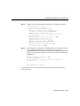
Step 8
In the following example, the router is configured for AppleTalk, Internet
Protocol (IP), and Internetwork Packet Exchange (IPX). Configure the
appropriate protocols for your router:
Configure Vines? [no]:
Configure LAT? [no]:
Configure AppleTalk? [no]: yes
Multizone networks? [no]: yes
Configure DECnet? [no]:
Configure IP? [yes]:
Configure IGRP routing? [yes]:
Your IGRP autonomous system number [1]: 15
Configure CLNS? [no]:
Configure bridging? [no]:
Configure IPX? [no]: yes
Configure XNS? [no]:
Configure Apollo? [no]:
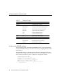
Step 9
If your router includes an ISDN BRI port, enter the ISDN BRI switch type. The
switch type appropriate for the router depends on the ISDN service provider’s
equipment. Table 4-1 lists the ISDN switch types.
Enter ISDN BRI Switch Type [none]: basic-5ess
Configuring the Router 4-7
Configuring the Router for the First Time
Table 4-1
ISDN Switch Types
Country
ISDN Switch Type
Description
Australia
basic-ts013
Australian TS013 switches
Europe
basic-1tr6
German 1TR6 ISDN switches
basic-nwnet3
Norwegian NET3 ISDN switches (phase 1)
basic-net3
NET3 ISDN switches (UK and others)
basic-net5
NET5 switches (UK and Europe)
vn2
French VN2 ISDN switches
vn3
French VN3 ISDN switches
Japan
ntt
Japanese NTT ISDN switches
New Zealand
basic-nznet3
New Zealand NET3 switches
North America
basic-5ess
AT&T basic rate switches
basic-dms100
NT DMS-100 basic rate switches
basic-ni1
National ISDN-1 switches
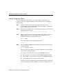
Configuring the ISDN BRI Interface
This section describes how to configure the ISDN BRI interface. If your router does not
include an ISDN BRI interface, proceed to the next section, “Configuring Ethernet or Token
Ring Interfaces.”
The ISDN BRI interface is configured to allow connection to ISDN WANs. Determine
which protocols to support on the ISDN BRI interface and enter the appropriate responses.
In the following example, the system is configured for IP, AppleTalk, and IPX:
Configuring interface BRI0:
Is this interface in use? [yes]
Configure IP on this interface? [yes]
IP address for this interface: 172.16.71.1
Number of bits in subnet field [0]: 8
Class B network is 172.16.0.0, 8 subnet bits; mask is
255.255.255.0
4-8 Router Installation and Configuration Guide
Configuring the Router for the First Time
Configure AppleTalk on this interface? [no]: yes
Extended AppleTalk network? [no]: yes
AppleTalk starting cable range [0]: 1
AppleTalk ending cable range [1]: 2
AppleTalk zone name [myzone]:
AppleTalk additional zone name: otherzone
AppleTalk additional zone name:
Configure IPX on this interface? [no]: yes
IPX network number [1]: B000
After you have completed the entire initial router configuration using the System
Configuration Dialog, proceed to the section “Configuring ISDN,” later in this chapter, for
additional ISDN configuration information.
Configuring Ethernet or Token Ring Interfaces
The Ethernet and Token Ring interfaces are configured to allow connection to a LAN. To
configure the interface parameters, you need to know your Ethernet or Token Ring interface
network addresses.
Take the following steps to configure an Ethernet or Token Ring interface to allow
communication over a LAN:
Step 1
Press Return or enter yes to configure the LAN interface:
Configuring interface Ethernet0:
Is this interface in use? [yes]:
Step 2
Determine which protocols you want to support on the LAN interface and enter
the appropriate responses. In the following example, the system is configured for
IP, AppleTalk, and IPX:
Configure IP on this interface? [yes]:
IP address for this interface: 172.16.72.1
Number of bits in subnet field [8]: 8
Class B network is 172.16.0.0, 8 subnet bits; mask is
255.255.255.0
Configuring the Router 4-9
Configuring the Router for the First Time
Configure AppleTalk on this interface? [no]: yes
Extended AppleTalk network? [no]: yes
AppleTalk starting cable range [0]: 3
AppleTalk ending cable range [1]: 3
AppleTalk zone name [myzone]:
AppleTalk additional zone name: otherzone
AppleTalk additional zone name:
Configure IPX on this interface? [no]: yes
IPX network number [1]: B001
Step 3
If there is more than one LAN interface on your router, repeat this procedure to
configure the second LAN interface.
Configuring the Synchronous Serial Interfaces
The synchronous serial interfaces are configured to allow connection to WANs. After the
Ethernet or Token Ring port on your router has been configured, take the following steps to
configure the synchronous serial interfaces:
Step 1
Press Return or enter yes to configure serial port 0:
Configuring interface Serial0:
Is this interface in use? [yes]:
Step 2
Determine which protocols you want on the synchronous serial interface and
enter the appropriate responses. In the following example, the system is
configured for IP, AppleTalk, and IPX:
Configure IP on this interface? [yes]:
Configure IP unnumbered on this interface? [no]:
IP address for this interface: 172.16.73.1
Number of bits in subnet field [8]:
Class B network is 172.16.0.0, 8 subnet bits; mask is
255.255.255.0
Configure AppleTalk on this interface? [no]: yes
Extended AppleTalk network? [yes]:
AppleTalk starting cable range [2]: 4
AppleTalk ending cable range [3]: 4
AppleTalk zone name [myzone]: ZZ Serial
AppleTalk additional zone name:
Configure IPX on this interface? [no]: yes
IPX network number [2]: B002
4-10 Router Installation and Configuration Guide
Configuring the Router for the First Time
Step 3
Configure the second synchronous serial interface, for example, as follows:
Configuring interface Serial1:
Is this interface in use? [yes]:
Configure IP on this interface? [yes]:
Configure IP unnumbered on this interface? [no]:
IP address for this interface: 172.16.74.2
Number of bits in subnet field [8]:
Class B network is 172.16.0.0, 8 subnet bits; mask is
255.255.255.0
Configure AppleTalk on this interface? [no]: yes
AppleTalk starting cable range [3]: 5
AppleTalk ending cable range [4]: 5
AppleTalk zone name [myzone]: ZZ Serial
AppleTalk additional zone name:
Configure IPX on this interface? [no]: yes
IPX network number [3]: B003
Step 4
The configuration you entered is now displayed and you are asked if you want
to use the displayed configuration. If you enter no, you will lose the
configuration information you just entered and you can begin the configuration
again. If you enter yes, the configuration will be entered and saved in the startup
configuration:
Use this configuration? [yes/no]: yes
Building configuration...
Use the enabled mode 'configure' command to modify this
configuration.
Press RETURN to get started!
Proceed to the section “Cisco IOS Software Basics” for more information about the
Cisco IOS software.
Configuring the Router 4-11
Configuring the Router for the First Time
Using Configuration Mode
You can configure the router manually if you do not want to use AutoInstall or the
prompt-driven System Configuration Dialog. Take the following steps to configure the
router manually:
Step 1
Connect a console terminal following the instructions in the section
“Connecting the Console Terminal and Modem” in the chapter “Installing the
Router,” and then power ON the router.
Step 2
When you are prompted to enter the initial dialog, enter no to go into the normal
operating mode of the router:
Would you like to enter the initial dialog? [yes]: no
Step 3
After a few seconds you will see the user EXEC prompt (Router>). Enter the
enable command to enter privileged EXEC mode. You can only make
configuration changes in privileged EXEC mode:
Router> enable
The prompt changes to the privileged EXEC prompt:
Router#
Step 4
Enter the configure terminal command at the privileged EXEC prompt to enter
configuration mode:
Router# configure terminal
You can now enter any changes you want to the configuration. You will probably
want to perform the following tasks:
(a)
Assign a host name for the router using the hostname command.
(b)
Enter an enable secret password using the enable password command.
(c)
Assign addresses to the interfaces using the protocol address command.
(d)
Specify which protocols to support on the interfaces.
Refer to the Cisco IOS configuration guide and command reference publications
for more information about the commands you can use to configure the router.
4-12 Router Installation and Configuration Guide
Configuring the Router for the First Time
Step 5
When you are finished configuring the router, enter the exit command until you
return to the privileged EXEC prompt (Router#).
Step 6
To save the configuration changes to NVRAM, enter the copy running-config
startup-config command at the privileged EXEC prompt.
Router# copy running-config startup-config
********
The router will now boot with the configuration you entered.
Using AutoInstall
The AutoInstall process is designed to configure the router automatically after connection
to your WAN. In order for AutoInstall to work properly, a Transmission Control
Protocol/Internet Protocol (TCP/IP) host on your network must be preconfigured to provide
the required configuration files. The TCP/IP host may exist anywhere on the network as
long as the following two conditions are maintained:
1 The host must be on the remote side of the router’s synchronous serial connection to the
WAN.
2 User Datagram Protocol (UDP) broadcasts to and from the router and the TCP/IP host
must be enabled.
This functionality is coordinated by your system administrator at the site where the TCP/IP
host is located. You should not attempt to use AutoInstall unless the required files have been
provided on the TCP/IP host. For more information, refer to the Cisco IOS configuration
guide and command reference publications.
Take the following steps to prepare your router for the AutoInstall process:
Step 1
Attach the WAN cable to the router.
Step 2
Power ON the router.
The router will load the operating system image from Flash memory. If the
remote end of the WAN connection is connected and properly configured, the
AutoInstall process will begin.
Configuring the Router 4-13
Cisco IOS Software Basics
Step 3
If AutoInstall completes successfully, enter the copy running-config
startup-config command in privileged EXEC mode to write the configuration
data to the router’s NVRAM:
Router# copy running-config startup-config
Taking this step saves the configuration settings that the AutoInstall process
created to the router’s NVRAM. If you do not do this, the configuration will be
lost the next time you reload the router.
Cisco IOS Software Basics
This section provides you with some basic information about the Cisco IOS software and
includes the following sections:
•
•
•
Cisco IOS Modes of Operation
Getting Context-Sensitive Help
Saving Configuration Changes
Cisco IOS Modes of Operation
The Cisco IOS software provides access to several different command modes. Each
command mode provides a different group of related commands.
For security purposes, the Cisco IOS software provides two levels of access to commands:
user and privileged. The unprivileged user mode is called user EXEC mode. The privileged
mode is called privileged EXEC mode and requires a password. The commands available
in user EXEC mode are a subset of the commands available in privileged EXEC mode.
Table 4-2 describes some of the most commonly used modes, how to enter the modes, and
the resulting prompts. The prompt helps you identify which mode you are in and, therefore,
which commands are available to you.
4-14 Router Installation and Configuration Guide
Cisco IOS Software Basics
Table 4-2
Mode of
Operation
Cisco IOS Operating Modes
Usage
How to Enter the Mode
Prompt
User EXEC
User EXEC commands allow you to
connect to remote devices, change
terminal settings on a temporary
basis, perform basic tests, and list
system information. The EXEC
commands available at the user level
are a subset of those available at the
privileged level.
Log in.
Router>
Privileged EXEC
Privileged EXEC commands set
operating parameters. The
privileged command set includes
those commands contained in user
EXEC mode, and also the configure
command through which you can
access the remaining command
modes. Privileged EXEC mode also
includes high-level testing
commands, such as debug.
From user EXEC mode, enter the
enable EXEC command.
Router#
Global
configuration
Global configuration commands
apply to features that affect the
system as a whole.
From global configuration mode,
enter the configure privileged
EXEC command.
Router(config)#
Configuring the Router 4-15
Cisco IOS Software Basics
Table 4-2
Mode of
Operation
Cisco IOS Operating Modes (Continued)
Usage
How to Enter the Mode
Prompt
Interface
configuration
Interface configuration commands
modify the operation of an interface
such as an Ethernet, Token Ring, or
serial port. Many features are
enabled on a per-interface basis.
Interface configuration commands
always follow an interface global
configuration command, which
defines the interface type.
From global configuration mode,
enter the interface type number
command. For example, enter the
interface serial 0 command to
configure the serial 0 interface.
Router(config-if)#
ROM monitor
ROM monitor commands are used
to perform low-level diagnostics.
You can also use the ROM monitor
commands to recover from a system
failure and stop the boot process in a
specific operating environment.1
From privileged EXEC mode,
enter the reload EXEC command.
Press Break during the first
60 seconds while the system is
booting.
>
1. You can modify the configuration register value using the config-reg configuration command. Refer to the Cisco IOS configuration
guide for more information.
Almost every configuration command also has a no form. In general, use the no form to
disable a feature or function. Use the command without the keyword no to reenable a
disabled feature or to enable a feature that is disabled by default. For example, IP routing
is enabled by default. To disable IP routing, enter the no ip routing command and enter
ip routing to reenable it. The Cisco IOS software command reference publication provides
the complete syntax for the configuration commands and describes what the no form of a
command does.
4-16 Router Installation and Configuration Guide
Cisco IOS Software Basics
Getting Context-Sensitive Help
In any command mode, you can get a list of available commands by entering a question
mark (?).
Router> ?
To obtain a list of commands that begin with a particular character sequence, type in those
characters followed immediately by the question mark (?). Do not include a space. This
form of help is called word help, because it completes a word for you.
Router# co?
configure connect
copy
To list keywords or arguments, enter a question mark in place of a keyword or argument.
Include a space before the question mark. This form of help is called command syntax help
because it reminds you which keywords or arguments are applicable based on the
command, keywords, and arguments you have already entered.
Router# configure ?
memory
Configure from NV memory
network
Configure from a TFTP network host
terminal Configure from the terminal
<cr>
You can also abbreviate commands and keywords by entering just enough characters to
make the command unique from other commands. For example, you can abbreviate the
show command to sh.
Saving Configuration Changes
Any time you make changes to the router configuration, you must save the changes to
memory because if you do not they will be lost if there is a system reload or power outage.
There are two types of configuration files: the running (current operating) configuration and
the startup configuration. The running configuration is stored in RAM; the startup
configuration is stored in NVRAM.
Configuring the Router 4-17
Configuring ISDN
To display the current running configuration, enter the show running-config command.
Enter the copy running-config startup-config command to save the current running
configuration to the startup configuration file in NVRAM.
Router> enable
Router# copy running-config startup-config
To display the startup configuration, enter the show startup-config command. Enter the
copy startup-config running-config command to write the startup configuration to the
running configuration:
Router> enable
Router# copy startup-config running-config
To erase both configuration files (and start over), enter the write erase and reload
commands:
Router> enable
Router# write erase
Router# reload
Caution This command sequence will erase the entire router configuration in RAM and
NVRAM and reload the router.
Configuring ISDN
This section describes a typical ISDN configuration for one or two B channels. In the
examples that follow, the BRI port is configured for IP routing, Challenge Handshake
Authentication Protocol (CHAP), and Point-to-Point Protocol (PPP) encapsulation.
For your reference, an example configuration follows in the next section, “Example ISDN
Configuration.” You may want to refer to it during this procedure.
4-18 Router Installation and Configuration Guide
Configuring ISDN
Take the following steps to configure the router for a basic ISDN PPP connection on a
single B channel or two B channels, substituting the correct addresses and host names as
appropriate for your network:
Step 1
Enter privileged EXEC mode:
Router> enable
password: enablepassword
Step 2
Enter the configure terminal command to enter global configuration mode.
Then enter the host name of the current router, the user name of the target router
(the router to which packets will be sent), and the password that the routers will
use for CHAP caller identification. The user name and password are case
sensitive and must match the host name and password of the target router (even
if it is not a Cisco router):
Router# configure terminal
Router (config)# hostname currentrouter
Router (config)# username targetrouter password abc
Step 3
Enter the isdn switch-type command to configure the ISDN switch type (such
as basic-5ess, basic-dms100, or basic-ni1). Refer to Table 4-1, earlier in this
chapter, for a list of ISDN switch types supported.
Router (config)# isdn switch-type switch-type
Step 4
Configure the IP address and subnet mask for the LAN interface:
Router (config)# interface type port_number
Router (config-if)# ip address ipaddress subnetmask
Step 5
Configure the IP address and subnet mask for the BRI interface:
Router (config-if)# interface bri port_number
Router (config-if)# ip address ipaddress subnetmask
Configuring the Router 4-19
Configuring ISDN
Step 6
If you are using an ISDN switch type (such as Basic NI1 or DMS-100) that
requires a service profile identifier (SPID), enter the SPID and optional local
directory number (LDN). The SPID and LDN are assigned by the ISDN service
provider.
The SPID is a number that identifies the service to which you have subscribed.
A SPID is not required for AT&T 5ESS service configured for a point-to-point
connection.
The LDN is an optional seven-digit phone number for the channel.
Router (config-if)# isdn spid1 SPID_no [LDN]
Router (config-if)# isdn spid2 SPID_no [LDN]
Step 7
Configure the router for PPP encapsulation and CHAP authentication:
Router (config-if)# encapsulation ppp
Router (config-if)# ppp authentication chap
Step 8
Enter the load-threshold or ppp multilink command to set up a second
B channel.
For bandwidth on demand, enter the load-threshold command to set the ISDN
load threshold. The load threshold determines the percentage of network load at
which the second ISDN B channel is activated. The value ranges from 1 to 255
(100 percent). In the following example, the value of 128 means that when the
first B channel reaches 50 percent of its bandwidth capacity (128 equals
50 percent of 255), the second B channel will activate to assist with the
bandwidth load:
Router (config-if)# dialer load-threshold 128
Alternatively, you can use Multilink PPP to activate a second ISDN line. For
Multilink PPP to work, the router must be running Cisco IOS Release 11.0(3) or
a later release, and both the current router and target router must support
Multilink PPP:
Router (config-if)# ppp multilink
4-20 Router Installation and Configuration Guide
Configuring ISDN
Step 9
Enter the dialer map command to provide the information necessary to
successfully route packets to the target router. Do not use periods or hyphens
when entering the number to dial:
Router (config-if)# dialer map protocol targetBRIport_ipaddress
name targetrouter_number
Step 10
Enter the dialer-group command to specify the number of the group permitted
to access the router:
Router (config-if)# dialer-group groupnumber
Step 11
Enter the exit command to exit interface configuration mode.
Step 12
Enter the dialer list command to specify the groups and protocols permitted to
access the router:
Router (config)# dialer-list groupnumber protocol protocol_type
permit
Step 13
Configure a static route to allow connection to the target router’s LAN. Enter the
IP address and subnet mask of the target router’s LAN interface, and the IP
address of the target router’s BRI port:
Router (config)# ip route targetrouter_ipnetwork subnetmask
targetBRIport_ipaddress
Step 14
Enter the exit command to exit global configuration mode.
Step 15
Enter the copy running-config startup-config command to save the
configuration to NVRAM.
Example ISDN Configuration
For your reference, Table 4-3 shows an example configuration for two Cisco routers using
IP over ISDN. In the example, the current router (branch1) is at a remote site and the target
router (main1) is at a central site.
Configuring the Router 4-21
Configuring ISDN
Table 4-3
Example ISDN Configuration
Configuration for the Current Router
Router> enable
password: pail1
Router# config term
Router (config)# hostname branch1
branch1 (config)# username main1
password secret1
branch1 (config)# isdn switch-type
basic-dms100
branch1 (config)# interface Ethernet 0
branch1 (config)# ip address
172.16.80.170 255.255.255.0
branch1 (config-if)# interface bri 0
branch1 (config-if)# ip address
172.16.71.1 255.255.255.0
branch1 (config-if)# isdn spid1
415988488501 9884885
branch1 (config-if)# isdn spid2
415988488602 9884886
branch1 (config-if)# dialer
load-threshold 128
branch1 (config-if)# ppp multilink
branch1 (config-if)# encapsulation ppp
branch1 (config-if)# ppp authentication
chap
branch1 (config-if)# dialer map ip
172.16.71.2 name main1 9884883
branch1 (config-if)# dialer group 1
branch1 (config-if)# exit
branch1 (config)# dialer-list 1 protocol ip
permit
branch1 (config-if)# ip route 172.16.0.0
255.255.0.0 172.16.71.2
branch1 (config-if)# ip route 0.0.0.0
172.16.71.2
branch1 (config)# exit
branch1# copy running-config
startup-config
branch1#
4-22 Router Installation and Configuration Guide
Configuration for the Target Router
Router> enable
password: pail2
Router# config term
Router (config)# hostname main1
main1 (config)# username branch1
password secret1
main1 (config)# isdn switch-type
basic-dms100
main1 (config)# interface Ethernet 0
main1 (config)# ip address 172.16.64.190
255.255.255.0
main1 (config-if)# interface bri 0
main1 (config-if)# ip address
172.16.71.2 255.255.255.0
main1 (config-if)# isdn spid1
415988488201 9884882
main1 (config-if)# isdn spid2
415988488302 9884883
main1 (config-if)# dialer
load-threshold 128
main1 (config-if)# ppp multilink
main1 (config-if)# encapsulation ppp
main1 (config-if)# ppp authentication
chap
main1 (config-if)# dialer map ip
172.16.71.1 name branch1 9884885
main1 (config-if)# dialer group 1
main1 (config-if)# exit
main1 (config)# dialer-list 1 protocol ip
permit
main1 (config-if)# ip route 172.16.80.0
255.255.0.0 172.16.71.1
main1 (config)# exit
main1# copy running-config
startup-config
main1#
Verifying Network Connectivity
Verifying Network Connectivity
After you have installed and configured the router, you can use the following commands in
user EXEC mode to verify network connectivity:
•
•
telnet—Logs in to a remote node
•
trace—Discovers the routes that packets take when traveling from one router to another
ping—Sends a special datagram to the destination device, then waits for a reply
datagram from that device
If there is a problem with network connectivity, refer to the section “Reading the LEDs” in
the appendix “Troubleshooting the Router” and check the cable connections. If there is still
a problem, check the router configuration.
Getting More Information
For more information about router software configuration, refer to the Cisco IOS
configuration guide and command reference publications. These publications are available
on the documentation CD that accompanied your router or you can order printed copies.
Refer to the section “Ordering Documentation” in the “Overview of the Router” chapter for
ordering information.
Configuring the Router 4-23
Getting More Information
4-24 Router Installation and Configuration Guide
A P PEN D I X
A
Troubleshooting the Router
This appendix contains information about how to isolate problems with the router and
includes the following sections:
•
•
Isolating Problems
Reading the LEDs
Isolating Problems
The key to problem solving in this system is to try to isolate the problem to a specific
subsystem. By comparing what the system is doing to what it should be doing, the task of
isolating the problem is greatly simplified.
When problem solving, consider the following subsystems:
•
•
Power and cooling systems—The power supply, power cable, and fan
Ports and cables—The ports on the rear panel of the router and the cables that connect
to them
Troubleshooting the Router A-1
Isolating Problems
Troubleshooting the Power and Cooling Systems
Check the following items to help isolate the problem:
•
When the power switch is in the ON position (|) and the System OK LED is on, are the
fans operating? If not, check the fans.
•
Does the router shutdown after being ON a short time? Check the environmental
conditions. The router might be overheating, resulting in a thermal-induced shutdown.
Ensure that the chassis intake and exhaust vents are clear. Review the section “General
Site Requirements” in the chapter “Preparing to Install the Router.” The operating
temperature for the router is 32 to 104° F (0 to 40°C).
•
•
Does the router fail to boot, but the System OK LED is on? Check the power supply.
Does the router constantly or intermittently reboot? There might be a problem with
either the processor or the software, or a DRAM SIMM might be installed incorrectly.
For information about obtaining technical support, refer to the section “Obtaining Service
and Support” in the “Overview of the Router” chapter.
Troubleshooting the Ports, Cables, and Connections
Check the following items to help isolate the problem:
•
•
Does the router fail to recognize a port? Check the cable connection.
•
Does the system boot, but the console screen is frozen? Verify that the console is
configured for 9600 baud, 8 data bits, no parity, and 2 stop bits.
When the power switch is in the ON position (|), is the System OK LED on? If not,
check the power source and power cable.
For information about obtaining technical support, refer to the section “Obtaining Service
and Support” in the “Overview of the Router” chapter.
A-2 Router Installation and Configuration Guide
Reading the LEDs
Reading the LEDs
The LEDs indicate the current operating condition of the router. You can observe the LEDs,
note any fault condition that the router is encountering, and then contact your system
administrator or customer service, if necessary. For information about how to contact
customer service, refer to the section “Obtaining Service and Support” in the “Overview of
the Router” chapter.
Figure A-1 to Figure A-7 show the location of the LEDs on the rear panel of the routers.
The power LED, at the right of the auxiliary port, lights up when the system is working
properly. All of the other LEDs indicate activity by flickering. When there is heavy activity
on a port, the LED might be ON constantly. If an LED is not ON when the port is active
and the cable is connected correctly, there might be a problem with the port.
Figure A-1
Synchronous
serial LEDs
System
OK LED
H4262
Ethernet
AUI LED
Model 2501 LEDs
Token Ring
LED
Model 2502 LEDs
Synchronous
serial LEDs
System
OK LED
H7578
Figure A-2
Troubleshooting the Router A-3
Reading the LEDs
Figure A-3
Synchronous
serial LEDs
ISDN
BRI LED
System
OK LED
H7579
Ethernet
AUI LED
Model 2503 LEDs
Figure A-4
Synchronous
serial LEDs
System
ISDN
BRI LED OK LED
H7580
Token Ring
LED
Model 2504 LEDs
Token Ring
LED
Ethernet
AUI LED
Model 2513 LEDs
Synchronous
serial LEDs
TOKEN RING
A-4 Router Installation and Configuration Guide
System
OK LED
H7581
Figure A-5
Reading the LEDs
Figure A-6
Synchronous
serial LEDs
System
OK LED
H7582
Ethernet
AUI LEDs
Model 2514 LEDs
Token Ring
LEDs
Model 2515 LEDs
Synchronous
serial LEDs
System
OK LED
H7583
Figure A-7
Troubleshooting the Router A-5
Reading the LEDs
A-6 Router Installation and Configuration Guide
A P PEN D I X
B
Maintaining the Router
This appendix contains selected maintenance procedures you might need to perform on the
router as your internetworking needs change.
This appendix includes the following sections:
•
•
•
•
Opening the Chassis
Upgrading the DRAM SIMM
Replacing the System-Code SIMMs
Closing the Chassis
Additional maintenance procedures are available on the documentation CD that
accompanied the router.
Caution Before opening the chassis, be sure that you have discharged all static electricity
from your body and the power is OFF. Before performing any procedures described in this
appendix, review the section “Safety Recommendations” in the chapter “Preparing to
Install the Router.”
Warning Before working on a chassis or working near power supplies, unplug the power
cord on AC units; disconnect the power at the circuit breaker on DC units. (To see translated
versions of this warning, refer to the Regulatory Compliance and Safety Information
document that accompanied your router.)
Maintaining the Router B-1
Opening the Chassis
Opening the Chassis
This section describes the procedure for opening the chassis by removing the chassis cover.
Warning Do not touch the power supply when the power cord is connected. For systems
with a power switch, line voltages are present within the power supply even when the power
switch is OFF and the power cord is connected. For systems without a power switch, line
voltages are present within the power supply when the power cord is connected. (To see
translated versions of this warning, refer to the Regulatory Compliance and Safety
Information document that accompanied your router.)
Tools Required
You will need the following tools to open the chassis:
•
•
Medium-size flat-blade screwdriver (1/4 inch [0.625 cm])
Size M 3.5 (metric) hex-head nut driver (optional)
Removing the Chassis Cover
You must open the chassis to access the internal components. When opening the chassis,
refer to Parts A and B in Figure B-1.
Warning Before opening the chassis, disconnect the telephone-network cables to avoid
contact with telephone-network voltages. (To see translated versions of this warning, refer
to the Regulatory Compliance and Safety Information document that accompanied your
router.)
Take the following steps to remove the chassis cover:
Step 1
Power OFF the router.
Step 2
Disconnect all cables from the rear panel of the router.
B-2 Router Installation and Configuration Guide
Opening the Chassis
Step 3
Turn the unit upside down so that the top of the chassis is resting on a flat
surface, and the front of the chassis is facing toward you. (See Figure B-1,
Part A.)
Step 4
Remove the single screw located on the bottom of the chassis (on the side closest
to you). Note that the chassis is comprised of two sections: top and bottom.
Step 5
If required, insert a medium-size flat-blade screwdriver into the slots shown in
Figure B-1, Part A, and gently rotate the blade so that the top and bottom
sections separate slightly.
Step 6
Holding the chassis with both hands, position it as shown in Figure B-1, Part B.
Step 7
Pull the top section away from the bottom section. (See Figure B-1, Part B.) The
fit is very snug, so it may be necessary to pry the chassis sections apart at one
end and then the other until they separate.
Figure B-1
Chassis Cover Removal
A
H7824
Flat-blade screwdriver
Screw
Slot
Slot
B
H3557
Top section
Bottom section
Rear
Left end
toward you
Front
Maintaining the Router B-3
Opening the Chassis
When the top cover is off, set it aside. Figure B-2 to Figure B-5 show the layout
of the system cards for models 2501 to 2504 and 2513 to 2515, respectively.
Figure B-2
Flash memory card socket
Polarization
notch
System Card Layout—Model 2501, 2502, 2503, and 2504 Routers
Primary memory
(DRAM SIMM)
System-code SIMMs
(Flash or PROMs)
CODE0
A
B
Shared memory
(fixed DRAM)
DRAM
Step 8
FW1
CODE1
FW2
H2351
Boot ROMs
Ethernet
Serial 0
B-4 Router Installation and Configuration Guide
Serial 1
BRI
Console Aux
Opening the Chassis
Figure B-3
Primary memory
(DRAM SIMM)
System-code SIMMs
(Flash or PROMs)
CODE1 CODE0
Flash memory card slot
System Card Layout—Model 2513 Router
J1
U3
A
J13
B
FW1
FW2
Boot ROM
jumper
Boot ROMs
Token Ring
J11
J12
H3788
J9
J10
Ethernet
Serial 0
Aux
Serial 1
Console
Note: SIMMs removed for clarity
Maintaining the Router B-5
Opening the Chassis
Figure B-4
Flash memory card slot
System Card Layout—Model 2514 Router
Boot ROMs
CODE1 CODE0
System-code SIMMs
(Flash or PROMs)
J1
Primary memory
(DRAM SIMM)
U3
A
J20
FW2
B
FW1
Boot ROM
jumper
J10
Ethernet
Ethernet
Serial 0
J12
H3786
J11
J9
Aux
Serial 1
Console
Note: SIMMs removed for clarity
B-6 Router Installation and Configuration Guide
Opening the Chassis
Figure B-5
System-code SIMMs
(Flash or PROMs)
Primary memory
(DRAM SIMM)
CODE1 CODE0
Flash memory card slot
System Card Layout—Model 2515 Router
J1
U3
FW2
A
Boot ROMs
B
FW1
J20
Boot ROM
jumper
J10
Token Ring
Token Ring
Serial 0
J12
H3787
J11
J9
Aux
Serial 1
Console
Note: SIMMs removed for clarity
Maintaining the Router B-7
Upgrading the DRAM SIMM
Upgrading the DRAM SIMM
This section describes how to upgrade the DRAM SIMM on the system card. You might
need to upgrade the DRAM SIMM for the following reasons:
•
•
You upgrade the Cisco IOS feature set or release.
Your router maintains large routing tables or other memory-intensive features, such as
spoofing or protocol translations.
To see how much memory is currently installed in the router, enter the show version
command. Near the middle of the resulting output, a message similar to the following
displays:
Cisco XXXX(68030) processor (revision X) with 4092K/2048K bytes of memory.
This line shows how much memory is installed (in this example, 4092K/2048K). The first
number represents primary memory and the second number represents shared memory.
Tools Required
You will need the following tools to remove and replace the DRAM SIMM on the router:
•
•
•
Medium-size flat-blade screwdriver (1/4 inch [0.625 cm])
ESD-preventive wrist strap
The DRAM SIMM required for your planned upgrade
DRAM SIMM Installation
Take the following steps to install the DRAM SIMMs:
Step 1
Power OFF the router.
Step 2
Attach an ESD-preventive wrist strap.
Step 3
Open the cover following the instructions in the section “Opening the Chassis”
earlier in this appendix.
B-8 Router Installation and Configuration Guide
Upgrading the DRAM SIMM
Step 4
Remove the existing DRAM SIMM by pulling outward on the connectors to
unlatch them, as shown in Figure B-6. Be careful not to break the holders on the
SIMM connector.
Caution To prevent damage, do not press on the center of the SIMMs. Handle each SIMM
carefully.
Position the new SIMM so that the polarization notch is located at the left end
of the SIMM socket. (See Figure B-6.)
Figure B-6
Removing and Replacing the DRAM SIMM
Pull the tabs away with
your thumbs, bracing your
forefingers against the
posts. Raise the SIMM
to a vertical position.
Connector edge of
the system card
Polarization notch
DRAM SIMM card
H6592
Step 5
Maintaining the Router B-9
Replacing the System-Code SIMMs
Step 6
Insert the new DRAM SIMM by sliding the end with the metal fingers into the
SIMM connector socket at approximately a 45-degree angle to the system card.
Gently rock the SIMM back into place until the latch on either side snaps into
place. Do not use excessive force because the connector may break.
Step 7
Replace the router cover. Follow the instructions in the section “Closing the
Chassis” later in this appendix.
Replacing the System-Code SIMMs
The system code (router operating system software) is stored in Flash memory SIMMs.
Tools Required
You will need the following tools to remove and replace the system-code SIMMs on the
router:
•
•
•
Medium-size flat-blade screwdriver (1/4 inch [0.625 cm])
ESD-preventive wrist strap
System-code SIMM(s)
Preparing to Install the System-Code SIMM
There are two system-code (Flash memory) SIMM sockets on the system board. If you
want to install system-code SIMMs in both sockets, the SIMMs must be the same size. For
example, if a 4-MB system-code SIMM is already installed in your router, the new SIMM
must also be 4 MB. This upgrade would give you a total of 8 MB. You can verify how much
Flash memory is already installed in your router by entering the show flash EXEC
command.
Caution The system code is stored on the Flash memory SIMMs, but new system-code
SIMMs are shipped without preinstalled software. Before proceeding with this procedure,
use the copy flash tftp EXEC command to back up the system code to a TFTP server.
B-10 Router Installation and Configuration Guide
Replacing the System-Code SIMMs
Note For more information about the copy flash tftp command and other related
commands, refer to the Cisco IOS configuration and command reference publications.
These publications are available on the documentation CD that came with your router or
you can order printed copies. Refer to the section “Ordering Documentation” in the chapter
“Overview of the Router” for ordering information.
System-Code SIMM Replacement
Take the following steps to upgrade the system-code Flash memory SIMMs:
Step 1
If you have not already done so, enter the copy flash tftp EXEC command to
back up the system code.
Step 2
Power OFF the router.
Step 3
Remove all cables from the rear panel of the router.
Step 4
Attach an ESD-preventive wrist or ankle strap.
Step 5
Open the chassis cover following the procedure in the section “Opening the
Chassis” earlier in this appendix.
Step 6
Locate the system-code SIMMs on the system card, labeled CODE0 and
CODE1. (See Figure B-2 to Figure B-5.)
Step 7
If necessary, remove the existing system-code SIMM by pulling outward on the
connector holders to unlatch them. The connector holds the SIMM tightly, so be
careful not to break the holders on the SIMM connector. (See Figure B-7.)
If you are installing system-code SIMMs in both sockets (CODE0 and CODE1),
both SIMMs must be the same size. For example, if a 4-MB system-code SIMM
is already installed in your router, the new SIMM must also be 4 MB. Populate
the SIMM socket labeled CODE0 first; then populate CODE1.
Caution To prevent damage, do not press on the center of the SIMMs. Handle each SIMM
carefully.
Maintaining the Router B-11
Replacing the System-Code SIMMs
Figure B-7
Removing and Replacing the System-Code SIMM
Pull the tabs away with
your thumbs, bracing your
forefingers against the
posts. Raise the SIMM
to a vertical position.
Connector edge of
the system card
Polarization notch
H6593
Flash memory SIMM card
Step 8
Position the new SIMM so that the polarization notch is located at the left end
of the SIMM socket.
Caution To prevent damage, note that some Flash memory SIMMs have the components
mounted on the rear side; therefore, when inserting the SIMM, always use the polarization
notch as a reference and not the position of the components on the SIMM.
B-12 Router Installation and Configuration Guide
Closing the Chassis
Step 9
Insert the new SIMM by sliding the end with the metal fingers into the
appropriate SIMM connector socket (labeled CODE0 or CODE1) at
approximately a 45-degree angle to the system card. Gently rock the SIMM back
into place until the latches on both sides snap into place. Do not use excessive
force because the connector may break.
Step 10
Replace the router cover following the procedure in the next section, “Closing
the Chassis.”
Closing the Chassis
This section describes the procedure for closing the chassis by replacing the cover.
Tools Required
You will need the following tools to replace the cover:
•
•
Medium-size flat-blade screwdriver (1/4 inch [0.625 cm])
Size M 3.5 hex-head nut driver (optional)
Replacing the Cover
Take the following steps to replace the cover:
Step 1
Position the two chassis sections, as shown in Figure B-8.
Step 2
Referring to Figure B-8, press the two chassis sections together and ensure the
following:
•
•
The top section fits into the rear of the bottom section. (See A in Figure B-8.)
•
Each side of the top and bottom sections fits together. (See C in Figure B-8.)
The bottom section fits into the front of the top section. (See B in
Figure B-8.)
Maintaining the Router B-13
Closing the Chassis
Caution To fit the two sections together, it may be necessary to work them together at one
end and then the other, working back and forth; however, use care to prevent bending the
chassis edges.
Figure B-8
Replacing the Chassis Cover
A
C
Top section
Bottom section
Left end
toward you
Front
H3560
Rear
B
Step 3
When the two sections fit together snugly, turn the chassis so that the bottom is
facing up, with the front panel toward you.
Step 4
Replace the cover screw. (See Figure B-1.) Tighten the screw to no more than
8 or 9 inch/pounds of torque.
Step 5
Reinstall the chassis on the wall, rack, desktop, or table.
Step 6
Replace all cables.
B-14 Router Installation and Configuration Guide
A P PEN D I X
C
Cable Specifications
This appendix provides the following pinout information:
•
•
•
•
•
Console and Auxiliary Port Signals and Pinouts
Ethernet Cable Assembly and Pinouts
Token Ring Port Pinouts
Synchronous Serial Cable Assemblies and Pinouts
ISDN BRI Port and Cable Pinouts
Note All pins not listed in the tables in this appendix are not connected.
If you prefer to order cables, refer to the section “Obtaining Service and Support” in the
“Overview of the Router” chapter for information about how to contact service.
Console and Auxiliary Port Signals and Pinouts
Your router comes with a console and auxiliary cable kit, which contains the cable and
adapters you need to connect a console terminal (an ASCII terminal or PC running terminal
emulation software) or modem to your router. The console and auxiliary cable kit includes
the following items:
•
RJ-45-to-RJ-45 roll-over cable. (See the next section, “Identifying a Roll-Over Cable,”
for more information.)
•
RJ-45-to-DB-9 female DTE adapter (labeled “TERMINAL”).
Cable Specifications C-1
Console and Auxiliary Port Signals and Pinouts
•
•
RJ-45-to-DB-25 female DTE adapter (labeled “TERMINAL”).
RJ-45-to-DB-25 male DCE adapter (labeled “MODEM”).
For console connections, proceed to the section “Console Port Signals and Pinouts” later in
this appendix; for modem connections, proceed to the section “Auxiliary Port Signals and
Pinouts” later in this appendix.
Identifying a Roll-Over Cable
You can identify a roll-over cable by comparing the two modular ends of the cable. Holding
the cables side-by-side, with the tab at the back, the wire connected to the pin on the outside
of the left plug should be the same color as the wire connected to the pin on the outside of
the right plug. (See Figure C-1.) If your cable came from Cisco Systems, pin 1 will be white
on one connector, and pin 8 will be white on the other (a roll-over cable reverses pins 1 and
8, 2 and 7, 3 and 6, and 4 and 5).
Figure C-1
Identifying a Roll-Over Cable
Pin 1 and pin 8
should be the
same color
Pin 8
H3824
Pin 1
C-2 Router Installation and Configuration Guide
Console and Auxiliary Port Signals and Pinouts
Console Port Signals and Pinouts
Use the thin, flat, RJ-45-to-RJ-45 roll-over cable and RJ-45-to-DB-9 female DTE adapter
(labeled “TERMINAL”) to connect the console port to a PC running terminal emulation
software. Figure C-2 shows how to connect the console port to a PC. Table C-1 lists the
pinouts for the asynchronous serial console port, the RJ-45-to-RJ-45 roll-over cable, and
the RJ-45-to-DB-9 female DTE adapter (labeled “TERMINAL”).
Figure C-2
Connecting the Console Port to a PC
PC
RJ-45-to-RJ-45
roll-over cable
RJ-45-to-DB-9 adapter
(labeled “TERMINAL”)
Table C-1
H7226
Router
Console Port Signaling and Cabling Using a DB-9 Adapter
Console
Port (DTE)
RJ-45-to-RJ-45
Roll-Over Cable
RJ-45-to-DB-9
Terminal Adapter
Console
Device
Signal
RJ-45 Pin
RJ-45 Pin
DB-9 Pin
Signal
RTS
11
8
8
CTS
DTR
2
7
6
DSR
TxD
3
6
2
RxD
GND
4
5
5
GND
GND
5
4
5
GND
RxD
6
3
3
TxD
DSR
7
2
4
DTR
CTS
81
1
7
RTS
1. Pin 1 is connected internally to Pin 8.
Cable Specifications C-3
Console and Auxiliary Port Signals and Pinouts
Use the thin, flat, RJ-45-to-RJ-45 roll-over cable and RJ-45-to-DB-25 female DTE adapter
(labeled “TERMINAL”) to connect the console port to a terminal. Figure C-3 shows how
to connect the console port to a terminal. Table C-2 lists the pinouts for the asynchronous
serial console port, the RJ-45-to-RJ-45 roll-over cable, and the RJ-45-to-DB-25 female
DTE adapter (labeled “TERMINAL”).
Figure C-3
Connecting the Console Port to a Terminal
Terminal
RJ-45-to-RJ-45
roll-over cable
RJ-45-to-DB-25 adapter
(labeled “TERMINAL”)
Table C-2
H7227
Router
Console Port Signaling and Cabling Using a DB-25 Adapter
Console
Port (DTE)1
RJ-45-to-RJ-45
Roll-Over Cable
RJ-45-to-DB-25
Terminal Adapter
Console
Device
Signal
RJ-45 Pin
RJ-45 Pin
DB-25 Pin
Signal
2
RTS
1
8
5
CTS
DTR
2
7
6
DSR
TxD
3
6
3
RxD
GND
4
5
7
GND
GND
5
4
7
GND
RxD
6
3
2
TxD
DSR
7
2
20
DTR
1
4
RTS
CTS
1
8
1. You can use the same cabling to connect a console to the auxiliary port.
2. Pin 1 is connected internally to Pin 8.
C-4 Router Installation and Configuration Guide
Console and Auxiliary Port Signals and Pinouts
Auxiliary Port Signals and Pinouts
Use the thin, flat, RJ-45-to-RJ-45 roll-over cable and RJ-45-to-DB-25 male DCE adapter
(labeled “MODEM”) to connect the auxiliary port to a modem. Figure C-4 shows how to
connect the auxiliary port to a modem. Table C-3 lists the pinouts for the asynchronous
serial auxiliary port, the RJ-45-to-RJ-45 roll-over cable, and the RJ-45-to-DB-25 male
DCE adapter (labeled “MODEM”).
Figure C-4
Connecting the Auxiliary Port to a Modem
RJ-45-to-RJ-45
rollover cable
Modem
RJ-45-to-DB-25 adapter
(labeled Modem)
Table C-3
H6094
Router
Auxiliary Port Signaling and Cabling Using a DB-25 Adapter
Auxiliary
Port (DTE)
RJ-45-to-RJ-45
Roll-Over Cable
RJ-45-to-DB-25
Modem Adapter
Modem
Signal
RJ-45 Pin
RJ-45 Pin
DB-25 Pin
Signal
RTS
11
8
4
RTS
DTR
2
7
20
DTR
TxD
3
6
3
TxD
GND
4
5
7
GND
GND
5
4
7
GND
RxD
6
3
2
RxD
DSR
7
2
8
DCD
1
5
CTS
CTS
1
8
1. Pin 1 is connected internally to Pin 8.
Cable Specifications C-5
Ethernet Cable Assembly and Pinouts
Ethernet Cable Assembly and Pinouts
This section describes the pinouts for an Ethernet AUI cable.
Figure C-5 shows an Ethernet AUI cable assembly, and Table C-4 lists the cable pinouts.
Figure C-5
Ethernet AUI Cable Assembly
J1-1
J1-9
J1
J2
-15
J1-8
H1031a
J2-1
J2-9
J2-15
J2-8
Table C-4
Ethernet AUI Cable Pinouts (DB-15)
Pin
Ethernet
Circuit
Signal
3
DO-A
Data Out Circuit A
10
DO-B
Data Out Circuit B
11
DO-S
Data Out Circuit Shield
5
DI-A
Data In Circuit A
12
DI-B
Data In Circuit B
4
DI-S
Data In Circuit Shield
2
CI-A
Control In Circuit A
9
CI-B
Control In Circuit B
1
CI-S
Control In Circuit Shield
6
VC
Voltage Common
13
VP
Voltage Plus
C-6 Router Installation and Configuration Guide
Token Ring Port Pinouts
Table C-4
Ethernet AUI Cable Pinouts (DB-15) (Continued)
Pin
Ethernet
Circuit
Signal
14
VS
Voltage Shield (L25 and M25)
Shell
PG
Protective Ground
Token Ring Port Pinouts
Table C-5 lists the Token Ring port pinouts. Use a Token Ring lobe cable (not included) to
connect the Token Ring port to a MAU.
Table C-5
Token Ring Port (DB-9) Pinouts
9 Pin1
Signal
1
Receive
3
+5V2
5
Transmit
6
Receive
9
Transmit
1. Pins 2, 4, 7, and 8 are ground.
2. 600 mA maximum.
Synchronous Serial Cable Assemblies and Pinouts
The illustrations and tables in this section provide assembly drawings and pinouts for the
EIA-530 DCE, EIA/TIA-232, EIA/TIA-449, V.35, and X.21 DTE and DCE cables, which
are used with the synchronous serial WAN port (labeled “SERIAL”).
Cable Specifications C-7
Synchronous Serial Cable Assemblies and Pinouts
EIA-530
Figure C-6 shows the EIA-530 serial cable assembly, and Table C-6 lists the pinouts.
Arrows indicate signal direction: —> indicates DTE to DCE, and <— indicates DCE to
DTE.
Figure C-6
EIA-530 Serial Cable Assembly
J1-46
J1-45
J1-16
J1-15
60-pin connector
25-pin connector
H1972
J2-13
J2-25
J2-14
J2-1
J1-1
J1-30
J1-31
J1-60
Connectors are not to scale
Table C-6
EIA-530 DTE Cable Pinouts (DB-60 to DB-25)
60 Pin
Signal
25 Pin
Signal
Direction
DTE DCE1
J1-11
TxD/RxD+
J2-2
BA(A), TxD+
—>
J1-12
TxD/RxD–
J2-14
BA(B), TxD–
—>
J1-28
RxD/TxD+
J2-3
BB(A), RxD+
<—
J1-27
RxD/TxD–
J2-16
BB(B), RxD–
<—
J1-9
RTS/CTS+
J2-4
CA(A), RTS+
—>
J1-10
RTS/CTS–
J2-19
CA(B), RTS–
—>
C-8 Router Installation and Configuration Guide
Synchronous Serial Cable Assemblies and Pinouts
Table C-6
EIA-530 DTE Cable Pinouts (DB-60 to DB-25) (Continued)
60 Pin
Signal
25 Pin
Signal
Direction
DTE DCE1
J1-1
CTS/RTS+
J2-5
CB(A), CTS+
<—
J1-2
CTS/RTS–
J2-13
CB(B), CTS–
<—
J1-3
DSR/DTR+
J2-6
CC(A), DSR+
<—
J1-4
DSR/DTR–
J2-22
CC(B), DSR–
<—
J1-46
Shield_GND
J2-1
Shield
Shorted
J1-47
MODE_2
–
–
J1-48
GND
–
–
J1-49
MODE_1
–
–
J1-5
DCD/DCD+
J2-8
CF(A), DCD+
<—
J1-6
DCD/DCD–
J2-10
CF(B), DCD–
<—
J1-24
TxC/RxC+
J2-15
DB(A), TxC+
<—
J1-23
TxC/RxC–
J2-12
DB(B), TxC–
<—
J1-26
RxC/TxCE+
J2-17
DD(A), RxC+
<—
J1-25
RxC/TxCE–
J2-9
DD(B), RxC–
<—
J1-44
LL/DCD
J2-18
LL
—>
J1-45
Circuit_GND
J2-7
Circuit_ GND
–
J1-7
DTR/DSR+
J2-20
CD(A), DTR+
—>
J1-8
DTR/DSR–
J2-23
CD(B), DTR–
—>
J1-13
TxCE/TxC+
J2-24
DA(A), TxCE+
—>
J1-14
TxCE/TxC–
J2-11
DA(B), TxCE–
—>
J1-51
GND
—
—
Shorted
J1-52
MODE_DCE
—
—
Shorted
1. The EIA-530 interface operates in DTE mode only. A DCE cable is not
available for the EIA-530 interface.
Cable Specifications C-9
Synchronous Serial Cable Assemblies and Pinouts
EIA/TIA-232
Figure C-7 shows the EIA/TIA-232 cable assembly. Table C-7 lists the DTE pinouts.
Table C-8 lists the DCE pinouts. Arrows indicate signal direction: —> indicates DTE to
DCE, and <— indicates DCE to DTE.
Figure C-7
EIA/TIA-232 Cable Assembly
J1-46
J1-45
J1-16
J1-15
60-pin connector
25-pin connector
H1972
J2-13
J2-25
J2-14
J2-1
J1-1
J1-30
J1-31
J1-60
Connectors are not to scale
Table C-7
EIA/TIA-232 DTE Cable Pinouts (DB-60 to DB-25)
60 Pin
Signal
Description
Direction
25 Pin
Signal
J1-50
MODE_0
Shorting group
–
–
–
J1-51
GND
J1-52
MODE_DCE
J1-46
Shield GND
Single
–
J2-1
Shield GND
J1-41
TxD/RxD
Twisted pair no. 5
—>
J2-2
TxD
Shield
–
–
Shield
–
C-10 Router Installation and Configuration Guide
Synchronous Serial Cable Assemblies and Pinouts
Table C-7
EIA/TIA-232 DTE Cable Pinouts (DB-60 to DB-25) (Continued)
60 Pin
Signal
Description
Direction
25 Pin
Signal
J1-36
RxD/TxD
Twisted pair no. 9
<—
J2-3
RxD
Shield
–
–
Shield
–
J1-42
RTS/CTS
—>
J2-4
RTS
Shield
–
–
Shield
–
J1-35
CTS/RTS
Shield
–
J1-34
DSR/DTR
Shield
–
J1-45
Circuit GND
Shield
–
J1-33
DCD/LL
Shield
–
J1-37
TxC/NIL
Shield
–
J1-38
RxC/TxCE
Shield
–
J1-44
LL/DCD
Shield
–
J1-43
DTR/DSR
Shield
–
J1-39
TxCE/TxC
Shield
–
Twisted pair no. 4
Twisted pair no. 10
Twisted pair no. 11
Twisted pair no. 1
Twisted pair no. 12
Twisted pair no. 8
Twisted pair no. 7
Twisted pair no. 2
Twisted pair no. 3
Twisted pair no. 6
<—
J2-5
CTS
–
Shield
–
<—
J2-6
DSR
–
Shield
–
–
J2-7
Circuit GND
–
Shield
–
<—
J2-8
DCD
–
Shield
–
<—
J2-15
TxC
–
Shield
–
<—
J2-17
RxC
–
Shield
–
—>
J2-18
LTST
–
Shield
–
—>
J2-20
DTR
–
Shield
–
—>
J2-24
TxCE
–
Shield
–
Cable Specifications C-11
Synchronous Serial Cable Assemblies and Pinouts
Table C-8
EIA/TIA-232 DCE Cable Pinouts (DB-60 to DB-25)
60 Pin
Signal
Description
Direction
25 Pin
Signal
J1-50
MODE_0
Shorting group
–
–
–
J1-51
GND
J1-46
Shield GND
Single
–
J2-1
Shield GND
J1-36
RxD/TxD
Twisted pair no. 9
<—
J2-2
TxD
Shield
–
–
Shield
–
J1-41
TxD/RxD
Shield
–
J1-35
CTS/RTS
Shield
–
J1-42
RTS/CTS
Shield
–
J1-43
DTR/DSR
Shield
–
J1-45
Circuit GND
Shield
–
J1-44
LL/DCD
Shield
–
J1-39
TxCE/TxC
Shield
–
J1-40
NIL/RxC
Shield
–
J1-33
DCD/LL
Shield
–
Twisted pair no. 5
Twisted pair no. 10
Twisted pair no. 4
Twisted pair no. 3
Twisted pair no. 1
Twisted pair no. 2
Twisted pair no. 7
Twisted pair no. 6
Twisted pair no. 12
C-12 Router Installation and Configuration Guide
—>
J2-3
RxD
–
Shield
–
<—
J2-4
RTS
–
Shield
–
—>
J2-5
CTS
–
Shield
–
—>
J2-6
DSR
–
Shield
–
Circuit GND
–
J2-7
–
Shield
—>
J2-8
DCD
–
Shield
–
—>
J2-15
TxC
–
Shield
–
—>
J2-17
RxC
–
Shield
–
<—
J2-18
LTST
–
Shield
–
Synchronous Serial Cable Assemblies and Pinouts
Table C-8
EIA/TIA-232 DCE Cable Pinouts (DB-60 to DB-25) (Continued)
60 Pin
Signal
Description
Direction
25 Pin
Signal
J1-34
DSR/DTR
Twisted pair no. 11
<—
J2-20
DTR
Shield
–
–
Shield
–
J1-38
RxC/TxCE
<—
J2-24
TxCE
Shield
–
–
Shield
–
Twisted pair no. 8
EIA/TIA-449
Figure C-8 shows the EIA/TIA-449 cable assembly. Table C-9 lists the DTE pinouts.
Table C-10 lists the DCE pinouts. Arrows indicate signal direction: —> indicates DTE to
DCE, and <— indicates DCE to DTE.
Figure C-8
60-pin connector (J1)
37-pin connector (J2)
J2-19
J2-37
H1973
J1-46
J1-45
J1-16
J1-15
EIA/TIA-449 Cable Assembly
J1-1
J1-30
J1-31
J1-60
Connectors are not to scale
J2-20
J2-1
Cable Specifications C-13
Synchronous Serial Cable Assemblies and Pinouts
Table C-9
EIA/TIA-449 DTE Cable Pinouts (DB-60 to DB-37)
60 Pin
Signal
Description
Direction
37 Pin
Signal
J1-49
MODE_1
Shorting group
–
–
–
J1-48
GND
J1-51
GND
Shorting group
–
–
–
J1-52
MODE_DCE
J1-46
Shield_GND
Single
_
J2-1
Shield GND
J1-11
TxD/RxD+
Twisted pair no. 6
—>
J2-4
SD+
J1-12
TxD/RxD–
—>
J2-22
SD–
J1-24
TxC/RxC+
<—
J2-5
ST+
J1-23
TxC/RxC–
<—
J2-23
ST–
J1-28
RxD/TxD+
<—
J2-6
RD+
J1-27
RxD/TxD–
<—
J2-24
RD–
J1-9
RTS/CTS+
—>
J2-7
RS+
J1-10
RTS/CTS–
—>
J2-25
RS–
J1-26
RxC/TxCE+
J1-25
RxC/TxCE–
J1-1
CTS/RTS+
J1-2
CTS/RTS–
J1-44
LL/DCD
J1-45
Circuit_GND
J1-3
DSR/DTR+
J1-4
DSR/DTR–
J1-7
DTR/DSR+
J1-8
DTR/DSR–
J1-5
DCD/DCD+
J1-6
DCD/DCD–
Twisted pair no. 9
Twisted pair no. 11
Twisted pair no. 5
Twisted pair no. 10
Twisted pair no. 1
Twisted pair no. 12
Twisted pair no. 2
Twisted pair no. 4
Twisted pair no. 3
C-14 Router Installation and Configuration Guide
<—
J2-8
RT+
<—
J2-26
RT–
<—
J2-9
CS+
<—
J2-27
CS–
—>
J2-10
LL
_
J2-37
SC
<—
J2-11
DM+
<—
J2-29
DM–
—>
J2-12
TR+
—>
J2-30
TR–
<—
J2-13
RR+
<—
J2-31
RR–
Synchronous Serial Cable Assemblies and Pinouts
Table C-9
EIA/TIA-449 DTE Cable Pinouts (DB-60 to DB-37) (Continued)
60 Pin
Signal
Description
Direction
37 Pin
Signal
J1-13
TxCE/TxC+
Twisted pair no. 7
—>
J2-17
TT+
J1-14
TxCE/TxC–
—>
J2-35
TT–
J1-15
Circuit_GND
–
J2-19
SG
J1-16
Circuit_GND
–
J2-20
RC
Table C-10
Twisted pair no. 9
EIA/TIA-449 DCE Cable Pinouts (DB-60 to DB-37)
60 Pin
Signal
Description
Direction
37 Pin
Signal
J1-49
MODE_1
Shorting group
–
–
–
J1-48
GND
J1-46
Shield_GND
Single
–
J2-1
Shield GND
J1-28
RxD/TxD+
Twisted pair no. 11
<—
J2-4
SD+
J1-27
RxD/TxD–
<—
J2-22
SD–
J1-13
TxCE/TxC+
—>
J2-5
ST+
J1-14
TxCE/TxC–
—>
J2-23
ST–
J1-11
TxD/RxD+
—>
J2-6
RD+
J1-12
TxD/RxD–
—>
J2-24
RD–
J1-1
CTS/RTS+
<—
J2-7
RS+
J1-2
CTS/RTS–
<—
J2-25
RS–
J1-24
TxC/RxC+
—>
J2-8
RT+
J1-23
TxC/RxC–
—>
J2-26
RT–
J1-9
RTS/CTS+
—>
J2-9
CS+
J1-10
RTS/CTS–
—>
J2-27
CS–
J1-29
NIL/LL
—>
J2-10
LL
J1-30
Circuit_GND
–
J2-37
SC
Twisted pair no. 7
Twisted pair no. 6
Twisted pair no. 1
Twisted pair no. 9
Twisted pair no. 5
Twisted pair no. 12
Cable Specifications C-15
Synchronous Serial Cable Assemblies and Pinouts
Table C-10
EIA/TIA-449 DCE Cable Pinouts (DB-60 to DB-37) (Continued)
60 Pin
Signal
Description
Direction
37 Pin
Signal
J1-7
DTR/DSR+
Twisted pair no. 4
—>
J2-11
DM+
J1-8
DTR/DSR–
—>
J2-29
DM–
J1-3
DSR/DTR+
<—
J2-12
TR+
J1-4
DSR/DTR–
<—
J2-30
TR–
J1-5
DCD/DCD+
—>
J2-13
RR+
J1-6
DCD/DCD–
—>
J2-31
RR–
J1-26
RxC/TxCE+
<—
J2-17
TT+
J1-25
RxC/TxCE–
<—
J2-35
TT–
J1-15
Circuit_GND
_
J2-19
SG
J1-16
Circuit_GND
_
J2-20
RC
Twisted pair no. 2
Twisted pair no. 3
Twisted pair no. 10
Twisted pair no. 8
V.35
Figure C-9 shows the V.35 cable assembly. Table C-11 lists the DTE pinouts. Table C-12
lists the DCE pinouts. Arrows indicate signal direction: —> indicates DTE to DCE, and
<— indicates DCE to DTE.
C-16 Router Installation and Configuration Guide
Synchronous Serial Cable Assemblies and Pinouts
V.35 Cable Assembly
60-pin connector (J1)
J1-46
J1-45
J1-16
J1-15
J1-1
J1-30
J1-31
J1-60
15-pin connector (J2)
J2-B
J2-D
J2-A
J2-C
J2-KK
J2-MM
J2-LL
J2-NN
Connectors are not to scale
Table C-11
H1975
Figure C-9
V.35 DTE Cable Pinouts (DB-60 to 34-Pin)
60 Pin
Signal
Description
Direction
34 Pin
Signal
J1-49
MODE_1
Shorting group
–
–
–
J1-48
GND
J1-50
MODE_0
Shorting group
–
–
–
J1-51
GND
J1-52
MODE_DCE
J1-53
TxC/NIL
Shorting group
–
–
–
J1-54
RxC_TxCE
J1-55
RxD/TxD
J1-56
GND
J1-46
Shield_GND
Single
–
J2-A
Frame GND
J1-45
Circuit_GND
Twisted pair no. 12
–
J2-B
Circuit GND
Shield
–
–
Shield
–
J1-42
RTS/CTS
—>
J2-C
RTS
Shield
–
–
Shield
–
Twisted pair no. 9
Cable Specifications C-17
Synchronous Serial Cable Assemblies and Pinouts
Table C-11
V.35 DTE Cable Pinouts (DB-60 to 34-Pin) (Continued)
60 Pin
Signal
Description
Direction
34 Pin
Signal
J1-35
CTS/RTS
Twisted pair no. 8
<—
J2-D
CTS
Shield
–
–
Shield
–
J1-34
DSR/DTR
<—
J2-E
DSR
Shield
–
–
Shield
–
J1-33
DCD/LL
<—
J2-F
RLSD
Shield
–
–
Shield
–
J1-43
DTR/DSR
—>
J2-H
DTR
Shield
–
–
Shield
–
J1-44
LL/DCD
—>
J2-K
LT
Shield
–
–
Shield
–
J1-18
TxD/RxD+
—>
J2-P
SD+
J1-17
TxD/RxD–
—>
J2-S
SD–
J1-28
RxD/TxD+
<—
J2-R
RD+
J1-27
RxD/TxD–
<—
J2-T
RD–
J1-20
TxCE/TxC+
—>
J2-U
SCTE+
J1-19
TxCE/TxC–
—>
J2-W
SCTE–
J1-26
RxC/TxCE+
<—
J2-V
SCR+
J1-25
RxC/TxCE–
<—
J2-X
SCR–
J1-24
TxC/RxC+
<—
J2-Y
SCT+
J1-23
TxC/RxC–
<—
J2-AA
SCT–
Table C-12
Twisted pair no. 7
Twisted pair no. 6
Twisted pair no. 10
Twisted pair no. 11
Twisted pair no. 1
Twisted pair no. 5
Twisted pair no. 2
Twisted pair no. 4
Twisted pair no. 3
V.35 DCE Cable Pinouts (DB-60 to 34-Pin)
60 Pin
Signal
Description
Direction
34 Pin
Signal
J1-49
MODE_1
Shorting group
–
–
–
J1-48
GND
C-18 Router Installation and Configuration Guide
Synchronous Serial Cable Assemblies and Pinouts
Table C-12
V.35 DCE Cable Pinouts (DB-60 to 34-Pin) (Continued)
60 Pin
Signal
Description
Direction
34 Pin
Signal
J1-50
MODE_0
Shorting group
–
–
–
J1-51
GND
J1-53
TxC/NIL
Shorting group
–
–
–
J1-54
RxC_TxCE
J1-55
RxD/TxD
J1-56
GND
J1-46
Shield_GND
Single
–
J2-A
Frame GND
J1-45
Circuit_GND
Twisted pair no. 12
–
J2-B
Circuit GND
Shield
–
–
Shield
–
J1-35
CTS/RTS
<—
J2-C
RTS
Shield
–
–
Shield
–
J1-42
RTS/CTS
—>
J2-D
CTS
Shield
–
–
Shield
–
J1-43
DTR/DSR
—>
J2-E
DSR
Shield
–
–
Shield
–
J1-44
LL/DCD
—>
J2-F
RLSD
Shield
–
–
Shield
–
J1-34
DSR/DTR
<—
J2-H
DTR
Shield
–
–
Shield
–
J1-33
DCD/LL
<—
J2-K
LT
Shield
–
–
Shield
–
J1-28
RxD/TxD+
<—
J2-P
SD+
J1-27
RxD/TxD–
<—
J2-S
SD–
J1-18
TxD/RxD+
—>
J2-R
RD+
J1-17
TxD/RxD–
—>
J2-T
RD–
J1-26
RxC/TxCE+
<—
J2-U
SCTE+
J1-25
RxC/TxCE–
<—
J2-W
SCTE–
Twisted pair no. 8
Twisted pair no. 9
Twisted pair no. 10
Twisted pair no. 11
Twisted pair no. 7
Twisted pair no. 6
Twisted pair no. 5
Twisted pair no. 1
Twisted pair no. 4
Cable Specifications C-19
Synchronous Serial Cable Assemblies and Pinouts
Table C-12
V.35 DCE Cable Pinouts (DB-60 to 34-Pin) (Continued)
60 Pin
Signal
Description
Direction
34 Pin
Signal
J1-22
NIL/RxC+
Twisted pair no. 3
—>
J2-V
SCR+
J1-21
NIL/RxC–
—>
J2-X
SCR–
J1-20
TxCE/TxC+
—>
J2-Y
SCT+
J1-19
TxCE/TxC–
—>
J2-AA
SCT–
Twisted pair no. 2
C-20 Router Installation and Configuration Guide
Synchronous Serial Cable Assemblies and Pinouts
X.21
Figure C-10 shows the X.21 cable assembly. Table C-13 lists the DTE pinouts. Table C-14
lists the DCE pinouts. Arrows indicate signal direction: —> indicates DTE to DCE, and
<— indicates DCE to DTE.
Figure C-10
X.21 Cable Assembly
J1-46
J1-45
J1-16
J1-15
60-pin connector (J1)
15-pin connector (J2)
H1974
J2-8
J2-15
J1-1
J1-30
J1-31
J1-60
J2-9
J2-1
Connectors are not to scale
Table C-13
X.21 DTE Cable Pinouts (DB-60 to DB-15)
60 Pin
Signal
Description
Direction
15 Pin
Signal
J1-48
GND
Shorting group
–
–
–
J1-47
MODE_2
J1-51
GND
Shorting group
–
–
–
J1-52
MODE_DCE
J1-46
Shield_GND
Single
–
J2-1
Shield GND
J1-11
TxD/RxD+
Twisted pair no. 3
—>
J2-2
Transmit+
J1-12
TxD/RxD–
—>
J2-9
Transmit–
Cable Specifications C-21
Synchronous Serial Cable Assemblies and Pinouts
Table C-13
X.21 DTE Cable Pinouts (DB-60 to DB-15) (Continued)
60 Pin
Signal
Description
Direction
15 Pin
Signal
J1-9
RTS/CTS+
Twisted pair no. 2
—>
J2-3
Control+
J1-10
RTS/CTS–
—>
J2-10
Control–
J1-28
RxD/TxD+
<—
J2-4
Receive+
J1-27
RxD/TxD–
<—
J2-11
Receive–
J1-1
CTS/RTS+
J1-2
CTS/RTS–
J1-26
RxC/TxCE+
J1-25
RxC/TxCE–
J1-15
Control_GND
Shield
–
Table C-14
Twisted pair no. 6
Twisted pair no. 1
Twisted pair no. 5
Twisted pair no. 4
<—
J2-5
Indication+
<—
J2-12
Indication–
<—
J2-6
Timing+
<—
J2-13
Timing–
–
J2-8
Control GND
–
Shield
–
X.21 DCE Cable Pinouts (DB-60 to DB-15)
60 Pin
Signal
Description
Direction
15 Pin
Signal
J1-48
GND
Shorting group
–
–
–
J1-47
MODE_2
J1-46
Shield_GND
Single
–
J2-1
Shield GND
J1-28
RxD/TxD+
Twisted pair no. 6
<—
J2-2
Transmit+
J1-27
RxD/TxD–
<—
J2-9
Transmit–
J1-1
CTS/RTS+
<—
J2-3
Control+
J1-2
CTS/RTS–
<—
J2-10
Control–
J1-11
TxD/RxD+
—>
J2-4
Receive+
J1-12
TxD/RxD–
—>
J2-11
Receive–
J1-9
RTS/CTS+
—>
J2-5
Indication+
J1-10
RTS/CTS–
—>
J2-12
Indication–
Twisted pair no. 1
Twisted pair no. 3
Twisted pair no. 2
C-22 Router Installation and Configuration Guide
ISDN BRI Port and Cable Pinouts
Table C-14
X.21 DCE Cable Pinouts (DB-60 to DB-15) (Continued)
60 Pin
Signal
Description
Direction
15 Pin
Signal
J1-24
TxC/RxC+
Twisted pair no. 4
—>
J2-6
Timing+
J1-23
TxC/RxC–
—>
J2-13
Timing–
J1-15
Control_GND
–
J2-8
Control GND
Shield
–
–
Shield
–
Twisted pair no. 5
ISDN BRI Port and Cable Pinouts
Table C-15 lists the ISDN BRI port pinouts. The straight-through RJ-45-to-RJ-45 cable,
used to connect to the ISDN BRI port, is not included.
Table C-15
BRI Port (RJ-45) Pinouts
RJ-45
8 Pin1
TE2
NT3
Polarity
3
Transmit
Receive
+
4
Receive
Transmit
+
5
Receive
Transmit
–
6
Transmit
Receive
–
1. Pins 1, 2, 7, and 8 are not used.
2. TE refers to terminal terminating layer 1 aspects of TE1,
TA, and NT2 functional groups.
3. NT refers to network terminating layer 1 aspects of NT1
and NT2 functional groups.
Cable Specifications C-23
ISDN BRI Port and Cable Pinouts
C-24 Router Installation and Configuration Guide
2
CHAPT E R
Preparing to Install the Cisco
Multiport Serial Routers
This chapter describes the tasks you must perform before you begin to install the
Cisco 2500 series multiport serial routers. It includes the following sections:
•
•
•
•
•
•
•
•
•
Safety Recommendations
General Site Requirements
Prerequisites for System Operation
Installation Checklist
Creating a Site Log
Cabling Considerations
Console and Auxiliary Port Considerations
Network Connection Considerations
Inspecting the System
Safety Recommendations
Follow these guidelines to ensure general safety:
•
•
•
•
Keep the chassis area clear and dust-free during and after installation.
Put the removed chassis cover in a safe place.
Keep tools away from walk areas where you and others could fall over them.
Do not wear loose clothing that could get caught in the chassis. Fasten your tie or scarf
and roll up your sleeves.
Preparing to Install the Cisco Multiport Serial Routers 2-1
Safety Recommendations
•
Wear safety glasses if you are working under any conditions that might be hazardous to
your eyes.
•
Do not perform any action that creates a potential hazard to people or makes the
equipment unsafe.
Maintaining Safety with Electricity
Follow these guidelines when working on equipment powered by electricity.
Warning Before working on equipment that is connected to power lines, remove jewelry
(including rings, necklaces, and watches). Metal objects will heat up when connected to
power and ground and can cause serious burns or can weld the metal object to the terminals.
(To see translated versions of this warning, refer to the appendix “Translated Safety
Warnings.”)
•
Locate the emergency power-off switch for the room in which you are working. Then,
if an electrical accident occurs, you can act quickly to turn off the power.
•
Disconnect all power by turning off the power and unplugging the power cord before
doing the following:
— Installing or removing a chassis
— Working near power supplies
•
•
Do not work alone if potentially hazardous conditions exist.
Never assume that power is disconnected from a circuit. Always check.
Warning Read the installation instructions before you connect the system to its power
source. (To see translated versions of this warning, refer to the appendix “Translated Safety
Warnings.”)
2-2 Cisco 2500 Series Multiport Serial Router User Guide
General Site Requirements
•
Look carefully for possible hazards in your work area, such as moist floors, ungrounded
power extension cables, frayed power cords, and missing safety grounds.
•
If an electrical accident occurs, proceed as follows:
— Use caution; do not become a victim yourself.
— Turn off power to the system.
— If possible, send another person to get medical aid. Otherwise, assess the condition
of the victim and then call for help.
— Determine if the person needs rescue breathing or external cardiac compressions;
then take appropriate action.
Preventing Electrostatic Discharge Damage
Electrostatic discharge (ESD) can damage equipment and impair electrical circuitry. It
occurs when electronic components are improperly handled and can result in complete or
intermittent failures.
Always follow ESD-prevention procedures when removing and replacing components.
Ensure that the chassis is electrically connected to earth ground. Wear an ESD-preventive
wrist strap, ensuring that it makes good skin contact. Connect the clip to an unpainted
surface of the chassis frame to safely channel unwanted ESD voltages to ground. To
properly guard against ESD damage and shocks, the wrist strap and cord must operate
effectively. If no wrist strap is available, ground yourself by touching the metal part of the
chassis.
Caution For safety, periodically check the resistance value of the antistatic strap, which
should be between 1 and 10 megohms.
General Site Requirements
This section describes the requirements your site must meet for safe installation and
operation of your system. Ensure that your site is properly prepared before beginning
installation.
The multiport serial routers can be placed on a desktop or mounted in a rack or on a wall.
Preparing to Install the Cisco Multiport Serial Routers 2-3
General Site Requirements
Warning Ultimate disposal of this product should be handled according to all national
laws and regulations. (To see translated versions of this warning, refer to the appendix
“Translated Safety Warnings.”)
Site Environment
The location of individual chassis and the layout of your equipment rack or wiring room
are extremely important for proper system operation. Equipment placed too close together,
inadequate ventilation, and inaccessible panels can cause system malfunctions and
shutdowns, and can make system maintenance difficult.
When planning your site layout and equipment locations, keep in mind the precautions
described in the next section, “Preventive Site Configuration,” to help avoid equipment
failures and reduce the possibility of environmentally caused shutdowns. If you are
currently experiencing shutdowns or unusually high errors with your existing equipment,
these precautions may help you isolate the cause of failures and prevent future problems.
Preventive Site Configuration
The following precautions will help you plan an acceptable operating environment for your
multiport serial router and will help you avoid environmentally caused equipment failures:
•
Electrical equipment generates heat. Ambient air temperature might not be adequate to
cool equipment to acceptable operating temperatures without adequate circulation.
Ensure that the room in which you operate your system has adequate air circulation.
•
Always follow the ESD-prevention procedures described in the section
“Safety Recommendations” earlier in this chapter to avoid damage to equipment.
Damage from static discharge can cause immediate or intermittent equipment failure.
•
Ensure that the chassis cover is secure. The chassis is designed to allow cooling air to
flow effectively within it. An open chassis allows air leaks, which may interrupt and
redirect the flow of cooling air from internal components.
2-4 Cisco 2500 Series Multiport Serial Router User Guide
General Site Requirements
Configuring Equipment Racks
The following tips will help you plan an acceptable equipment rack configuration:
•
Enclosed racks must have adequate ventilation. Ensure that the rack is not overly
congested because each unit generates heat. An enclosed rack should have louvered
sides and a fan to provide cooling air.
•
When mounting a chassis in an open rack, ensure that the rack frame does not block the
intake or the exhaust ports. If the chassis is installed on slides, check the position of the
chassis when it is seated all the way into the rack.
•
In an enclosed rack with a ventilation fan in the top, excessive heat generated by
equipment near the bottom of the rack can be drawn upward and into the intake ports of
the equipment above it in the rack.
•
Baffles can help to isolate exhaust air from intake air, which also helps to draw cooling
air through the chassis. The best placement of the baffles depends on the airflow patterns
in the rack, which are found by experimenting with different arrangements.
Power Supply Considerations
Check the power at your site to ensure that you are receiving “clean” power (free of spikes
and noise). Install a power conditioner if necessary.
Warning The device is designed to work with TN power systems. (To see translated
versions of this warning, refer to the appendix “Translated Safety Warnings.”)
The multiport serial router power supply includes the following features:
•
•
Autoselects either 110V or 220V operation.
All units include a 6-foot (1.8-meter) electrical power cord. (A label near the power cord
indicates the correct voltage, frequency, current draw, and power dissipation for your
unit.)
Preparing to Install the Cisco Multiport Serial Routers 2-5
Prerequisites for System Operation
Warning This product relies on the building’s installation for short-circuit (overcurrent)
protection. Ensure that a fuse or circuit breaker no larger than 120 VAC, 15A U.S.
(240 VAC, 10A international) is used on the phase conductors (all current-carrying
conductors). (To see translated versions of this warning, refer to the appendix “Translated
Safety Warnings.”)
Prerequisites for System Operation
The multiport serial routers run system code from Flash memory single in-line memory
modules (SIMMs). With the proper system code image, the multiport serial router can also
run from dynamic random-access memory (DRAM); however, this operation requires a
4-MB memory upgrade (installation of a 1 MB x 36 DRAM SIMM). In addition, operating
system code from DRAM can result in a 25 percent decrease in system performance.
Operating the system code from Flash memory is the default and is recommended for
optimum performance of the multiport serial routers.
2-6 Cisco 2500 Series Multiport Serial Router User Guide
Installation Checklist
Installation Checklist
The Installation Checklist lists the procedures for initial hardware installation of a new
multiport serial router. Make a copy of this checklist and mark the entries as you complete
each procedure. Include a copy of the checklist for each system in your Site Log. (See the
following section, “Creating a Site Log.”)
Installation checklist for site______________________________________________
Router name__________________________________________________________
Task
Verified by
Date
Installation checklist copied
Background information placed in Site Log
Site power voltages verified
Required tools available
Additional equipment available
Router received
Optional UniverCD or printed documentation
received
Chassis components verified
Initial electrical connections established
ASCII terminal or PC attached to console port
Signal distance limits verified
Startup sequence steps completed
Initial system operation verified
Software image verified
Preparing to Install the Cisco Multiport Serial Routers 2-7
Creating a Site Log
Creating a Site Log
The Site Log provides a record of all actions relevant to the system. Keep it near the chassis
where anyone who performs tasks has access to it. Use the Installation Checklist (see the
previous section “Installation Checklist”) to verify steps in the installation and maintenance
of your system. Site Log entries might include the following:
•
Installation progress—Make a copy of the Installation Checklist and insert it into the
Site Log. Make entries on the checklist as you complete each procedure.
•
Upgrades and maintenance procedures—Use the Site Log as a record of ongoing system
maintenance and expansion. Each time a procedure is performed on the system, update
the Site Log to reflect the following:
— Configuration changes
— Changes and updates to Cisco IOS software
— Maintenance schedules and requirements
— Corrective maintenance procedures performed
— Intermittent problems
— Related comments and notes
Cabling Considerations
When setting up your multiport serial router, consider distance limitations and potential
electromagnetic interference (EMI) as defined by the Electronic Industries Association
(EIA).
Warning The ports labeled “Ethernet,” “10BaseT,” “Token Ring,” “Console,” and “AUX”
are safety extra-low voltage (SELV) circuits. SELV circuits should only be connected to
other SELV circuits. Because the BRI circuits are treated like telephone-network voltage,
avoid connecting the SELV circuit to the telephone network voltage (TNV) circuits. (To see
translated versions of this warning, refer to the appendix “Translated Safety Warnings.”)
2-8 Cisco 2500 Series Multiport Serial Router User Guide
Cabling Considerations
Distance Limitations
Following are the distance limitation specifications for Ethernet, Token Ring, and serial
interfaces.
Ethernet Connections
The distance limitations for the IEEE 802.3 (10Base5 coaxial cable) specification indicate
a maximum segment distance of 1,640 feet (500 m) at a transmission rate of 10 megabits
per second (Mbps).
The distance limitations for Ethernet 10BaseT indicate a maximum segment distance of
328 feet (100 m); Ethernet 10Base2 has a maximum segment distance of 606 feet (185 m).
Token Ring Connections
The distance limitations for the IEEE 802.5 specification indicate a maximum segment
distance of 328 feet (100 m) at a transmission rate of 4 or 16 Mbps for unshielded
twisted-pair (UTP) cable. The distance limitation when using shielded twisted-pair (STP)
cabling is 1,640 feet (500 m).
Serial Connections
As with all signaling systems, EIA/TIA-232 signals can travel a limited distance at any
given bit rate; generally, the slower the data rate, the greater the distance. Table 2-1 shows
the standard relationship between baud rate and maximum distance.
Table 2-1
EIA/TIA-232 Speed and Distance Limitations
Data Rate
(Baud)
Distance
(Feet)
Distance
(Meters)
2400
200
60
4800
100
30
9600
50
15
19200
50
15
Preparing to Install the Cisco Multiport Serial Routers 2-9
Cabling Considerations
Data Rate
(Baud)
Distance
(Feet)
Distance
(Meters)
38400
50
15
57600
25
7.6
115200
12
3.7
The use of balanced drivers allows EIA/TIA-449 signals to travel greater distances than the
EIA/TIA-232 standard. Table 2-2 lists the standard relationship between baud rate and
maximum distance for EIA/TIA-449 signals. These limits are also valid for V.35 and X.21.
Table 2-2
EIA/TIA-449 Speed and Distance Limitations
Data Rate
(Baud)
Distance
(Feet)
Distance
(Meters)
2400
4,100
1,250
4800
2,050
625
9600
1,025
312
19200
513
156
38400
256
78
56000
102
31
T1
50
15
The EIA/TIA-449 and V.35 interfaces support data rates up to 2.048 Mbps.
Exceeding this maximum could result in loss of data and is not recommended.
Caution
2-10 Cisco 2500 Series Multiport Serial Router User Guide
Console and Auxiliary Port Considerations
Console and Auxiliary Port Considerations
This section discusses important cabling information that must be considered before you
connect the terminals or modems to console and auxiliary ports. The console port and the
auxiliary port are used to provide access to the system either locally or remotely.
Console Port Connections
Each multiport serial router includes an EIA/TIA-232 (RJ-45) console asynchronous serial
port. This port connects to a terminal using an RJ-45 cable and an RJ-45-to-DB-25 adapter
or a PC using the RJ-45 to DB-9 adapter. Depending on the cable and the adapter used, this
port appears as a data terminal equipment (DTE) or data communications equipment
(DCE) device at the end of the cable. To connect to a terminal, use an RJ-45 roll-over cable
with a female DTE connector (labeled Terminal) for connection to the console port. For
detailed information on installing the terminal, see the section “Connecting to the Console
Port” in the chapter “Installing the Cisco Multiport Serial Routers.”)
Table B-1 in the appendix “Cisco Multiport Router Cable Specifications” lists the pinout
for the console port. The default parameters for the console port are 9600 baud, 8 data bits,
no parity, and 2 stop bits. The console port does not support hardware flow control or
modem control.
Auxiliary Port Connections
An EIA/TIA-232 (RJ-45) auxiliary asynchronous serial port is included on all multiport
serial routers. This port can connect to a modem for remote maintenance or terminal
services. Use an RJ-45 roll-over cable with a male modem (MMOD) adapter (labeled
Modem) for this connection. For detailed information on connecting devices to the
auxiliary port, see the section “Connecting a Modem to the Auxiliary Port” in the chapter
“Installing the Cisco Multiport Serial Routers.” See Table B-1 in the appendix “Cisco
Multiport Router Cable Specifications” for the pinout for the auxiliary port.
Preparing to Install the Cisco Multiport Serial Routers 2-11
Network Connection Considerations
Network Connection Considerations
This sections describes important cabling information that must be considered before
making your network connections. The Ethernet or Token Ring ports are used to connect
to a LAN; the synchronous serial ports are used to connect to a WAN; and the asynchronous
ports are used to provide remote access to the multiport serial routers.
Ethernet Connections
The Ethernet ports are located on the rear panel of the Cisco 2520 (labeled ETHERNET 0
AUI and UTP) and Cisco 2522 (labeled ETHERNET 0 AUI and 10BT) multiport serial
routers. Both ports are active, but only one can be used at a time. If both ports are connected,
the 10BaseT port is active.Use an Ethernet transceiver to connect multiport serial routers
directly to the network.
You can use the following equipment to connect to the Ethernet AUI port:
•
•
An Ethernet AUI cable connected to a transceiver
An Ethernet transceiver connected directly to the multiport serial router’s AUI port
The connection to the AUI port can be made using either slide latch connectors or
jackscrew connectors
Note Ethernet cables are not shipped as standard with the multiport serial routers.
The 10BaseT port is connected to the Ethernet through the twisted-pair wiring, and is
modular in design.
Token Ring Connections
The two Token Ring ports are located on the rear panel of the Cisco 2521 and Cisco 2523
and are labeled TOKEN RING or UTP. The port labeled TOKEN RING uses a standard
9-pin Token Ring lobe cable and connects the multiport serial router directly to a media
2-12 Cisco 2500 Series Multiport Serial Router User Guide
Network Connection Considerations
attachment unit (MAU). The Token Ring port labeled UTP uses an RJ-45 Token Ring cable
and is connected through an adapter or directly to a MAU. Only one Token Ring port can
be used at a time.
Synchronous Serial Connections
The multiport serial routers offer two high-speed synchronous serial ports and from two to
eight (depending on which chassis you have) low-speed asynchronous/synchronous serial
interface ports that can be configured as synchronous serial interfaces.
The high-speed synchronous serial ports are located on the left of the rear panel and are
labeled SERIAL 0 and SERIAL 1.
The serial ports are 60-pin, D-type connectors. All serial interfaces (except the EIA-530)
can be configured as DTE or DCE, depending on the attached cable. The EIA-530 interface
is only configured as DTE. All DTE serial ports require that external clocking be provided
by a channel service unit/data service unit (CSU/DSU) or other DCE device.
You must use a special serial cable to connect a multiport serial router to a modem or
CSU/DSU. This cable is available from Cisco and is usually ordered with the system. The
cable uses a DB-60 connector on the chassis end. See the appendix “Cisco Multiport Router
Cable Specifications” for cable pinouts. For ordering information, contact a customer
service representative.
Note Because of the small size of the pins on the DB-60 serial connector, attempting to
manufacture your own serial cables is not recommended.
Asynchronous/synchronous Serial Connections
The asynchronous/synchronous serial ports use the asynchronous/synchronous 60-pin
connectors located on the rear panel. The lower ports are labeled SERIAL 2 (A/S) and
SERIAL 3 (A/S): the upper ports (depending on which chassis you have) are labeled
SERIAL 4 (A/S) through SERIAL 9 (A/S).
Preparing to Install the Cisco Multiport Serial Routers 2-13
Network Connection Considerations
You must use a special serial cable to connect a multiport serial router to a modem or
CSU/DSU. This cable is available from Cisco and is usually ordered with the system. The
cable uses a DB-60 connector on the chassis end. See the appendix “Cisco Multiport Router
Cable Specifications” for cable pinouts. For ordering information, contact a customer
service representative.
BRI Connections
On models with a Basic Rate Interface (BRI) port, the BRI port is an RJ-45 8-pin connector
located between the UTP and console ports on the Cisco 2520 and Cisco 2521, or between
the 10BT and console ports on the Cisco 2522 and Cisco 2523. Use an appropriate cable to
connect the system directly to the Integrated Services Digital Network (ISDN) through the
NT1. The common carrier will provide the NT1 connection worldwide, except in North
America, where the NT1 is customer owned.
Warning Network hazardous voltages are accessible in the BRI cable. If you detach the
BRI cable, detach the end away from the multiport serial router first to avoid possible
electric shock. Network hazardous voltages also are accessible on the system card in the
area of the BRI port (RJ-45 connector), regardless of whether power is turned off. (To see
translated versions of this warning, refer to the appendix “Translated Safety Warnings.”)
Warning The ISDN connection is regarded as a source of voltage that should be
inaccessible to user contact. Do not attempt to tamper with or open any public telephone
operator (PTO)-provided equipment or connection hardware. Any hardwired connection
(other than by nonremovable, connect-one-time-only lug) must be made only by PTO staff
or suitably trained engineers. (To see translated versions of this warning, refer to the
appendix “Translated Safety Warnings.”)
2-14 Cisco 2500 Series Multiport Serial Router User Guide
Inspecting the System
Inspecting the System
Do not unpack the multiport serial router until you are ready to install it. If the final
installation site will not be ready for some time, keep the chassis in its shipping container
to prevent accidental damage. When you have determined where you want the multiport
serial router installed, proceed with the unpacking.
The multiport serial router, cables, UniverCD or printed publications, and any optional
equipment you ordered might be shipped in more than one container. When you unpack
each shipping container, check the packing list to ensure that you received the following
items:
•
•
•
•
Multiport serial router
•
Optional equipment (such as network interface cables and asynchronous breakout
cables)
•
Cisco Information Packet publication, UniverCD and optional printed publications, as
specified on your order
6-foot (1.8-meter) power cord
Jackscrews for the AUI connector
Console and auxiliary cabling kit (two RJ-45 roll-over cables, one terminal adapter, one
DB-9 PC adapter, and one modem adapter)
Inspect all items for shipping damage. If anything appears to be damaged, or if you
encounter problems when installing or configuring your system, contact a customer service
representative.
Preparing to Install the Cisco Multiport Serial Routers 2-15
Inspecting the System
2-16 Cisco 2500 Series Multiport Serial Router User Guide