1
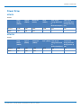
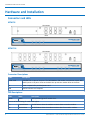
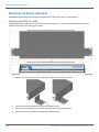
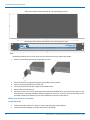
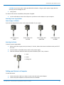
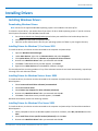
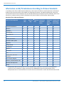
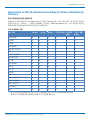
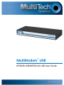
MultiModem® USB
MTMC8-USB/MTMC16-USB User Guide
MTMC ADMINISTRATOR GUIDE
MTMC Administrator Guide
Models: MTMC8 and MTMC16
Part Number: S000588, Version 1.1.0
Copyright
This publication may not be reproduced, in whole or in part, without the specific and express prior written permission signed by an executive officer of
Multi-Tech Systems, Inc. All rights reserved. Copyright © 2014 by Multi-Tech Systems, Inc.
Multi-Tech Systems, Inc. makes no representations or warranties, whether express, implied or by estoppels, with respect to the content, information,
material and recommendations herein and specifically disclaims any implied warranties of merchantability, fitness for any particular purpose and noninfringement.
Multi-Tech Systems, Inc. reserves the right to revise this publication and to make changes from time to time in the content hereof without obligation of
Multi-Tech Systems, Inc. to notify any person or organization of such revisions or changes.
Trademarks
MultiModem, Multi-Tech, and the Multi-Tech logo are registered trademarks of Multi-Tech Systems, Inc. All other products and technologies are the
trademarks or registered trademarks of their respective holders.
Legal Notices
The Multi-Tech products are not designed, manufactured or intended for use, and should not be used, or sold or re-sold for use, in connection with
applications requiring fail-safe performance or in applications where the failure of the products would reasonably be expected to result in personal injury or
death, significant property damage, or serious physical or environmental damage. Examples of such use include life support machines or other life
preserving medical devices or systems, air traffic control or aircraft navigation or communications systems, control equipment for nuclear facilities, or
missile, nuclear, biological or chemical weapons or other military applications (“Restricted Applications”). Use of the products in such Restricted
Applications is at the user’s sole risk and liability.
Contacting Multi-Tech
Knowledge Base
The Knowledge Base provides immediate access to support information and resolutions for all Multi-Tech products. Visit http://www.multitech.com/kb.go.
Support Portal
To create an account and submit a support case directly to our technical support team, visit: https://support.multitech.com.
Support
Business Hours: M-F, 8am to 5pm CT
Country
By Email
By Phone
Europe, Middle East, Africa:
[email protected]
+(44) 118 959 7774
U.S., Canada, all others:
[email protected]
(800) 972-2439 or (763) 717-5863
Warranty
To read the warranty statement for your product, visit www.multitech.com/warranty.go. For other warranty options, visit www.multitech.com/es.go.
World Headquarters
Multi-Tech Systems, Inc.
2205 Woodale Drive, Mounds View, MN 55112
Phone: (800) 328-9717 or (763) 785-3500
Fax (763) 785-9874
2
MultiModem® USB MTMC8-USB/MTMC16-USB User Guide
CONTENTS
Contents
Product Overview .................................................................................................................................................... 5
Overview ....................................................................................................................................................................... 5
Documentation ........................................................................................................................................................... 5
Package Contents.......................................................................................................................................................... 5
Safety Warnings ............................................................................................................................................................ 5
Analog Telecom Safety Warnings .............................................................................................................................. 5
Specifications ................................................................................................................................................................ 6
Power Draw................................................................................................................................................................... 7
MTMC8........................................................................................................................................................................ 7
MTMC16...................................................................................................................................................................... 7
Hardware and Installation ....................................................................................................................................... 8
Connectors and LEDs .................................................................................................................................................... 8
MTMC 8....................................................................................................................................................................... 8
MTMC 16..................................................................................................................................................................... 8
Connector Descriptions............................................................................................................................................... 8
LED Descriptions ......................................................................................................................................................... 8
Mounting the Device (Optional) ................................................................................................................................. 10
Mounting an MTMC on a Wall.................................................................................................................................. 10
Mounting the Device in a Rack ................................................................................................................................. 11
Cabling your Device to a Computer .......................................................................................................................... 13
Installing Drivers .................................................................................................................................................... 15
Installing Windows Drivers ......................................................................................................................................... 15
Downloading Windows Drivers................................................................................................................................. 15
Installing Drivers for Windows 7, 8 or Server 2012 .................................................................................................. 15
Installing Drivers for Windows Vista or Server 2008 ............................................................................................... 15
Installing Drivers for Windows XP or Server 2003 .................................................................................................... 15
Installing Linux Drivers ................................................................................................................................................ 16
Downloading Linux Drivers ....................................................................................................................................... 16
Installing Linux .......................................................................................................................................................... 16
Regulatory Information.......................................................................................................................................... 17
47 CFR Part 15 Regulation Class A Devices ................................................................................................................. 17
47 CFR Part 68 Telecom .............................................................................................................................................. 17
Fax Branding Statement.............................................................................................................................................. 19
Canadian Limitations................................................................................................................................................... 19
Industry Canada Class A Notice .................................................................................................................................. 19
EMC, Safety, and R&TTE Directive Compliance ......................................................................................................... 19
MultiModem® USB MTMC8-USB/MTMC16-USB User Guide
3
CONTENTS
Labeling Requirements .......................................................................................................................................... 20
United States Labeling Requirement (for Dial-Up Modems) ...................................................................................... 20
Label Physical Characteristics ................................................................................................................................... 20
Labeling Continuity and Changes ............................................................................................................................. 21
Other Label Requirements........................................................................................................................................ 21
Canadian Labeling Requirements (for Dial-Up Modems) ........................................................................................... 21
Environmental Notices........................................................................................................................................... 23
Waste Electrical and Electronic Equipment Statement .............................................................................................. 23
WEEE Directive.......................................................................................................................................................... 23
Instructions for Disposal of WEEE by Users in the European Union ........................................................................ 23
REACH Statement ....................................................................................................................................................... 24
Registration of Substances........................................................................................................................................ 24
Substances of Very High Concern (SVHC) ................................................................................................................ 24
Restriction of the Use of Hazardous Substances (RoHS) ............................................................................................ 25
Information on HS/TS Substances According to Chinese Standards ......................................................................... 26
Information on HS/TS Substances According to Chinese Standards (in Chinese) ...................................................... 27
Index...................................................................................................................................................................... 28
4
MultiModem® USB MTMC8-USB/MTMC16-USB User Guide
PRODUCT OVERVIEW
Product Overview
Overview
Use the MultiModem USB modem concentrator for analog dial-up remote access, modem pooling, or as dedicated
fax server solution for Windows® and Linux® environments. It provides eight or sixteen built-in V.92/56K modems.
The MultiModem USB modem concentrator also offers V.34/33.6K Super G3 fax, and Error Correction Mode, which
can reduce fax transmission time by more than half when compared to traditional fax modems.
Documentation
Multi-Tech provides the following manuals for use with the MultiModem USB modem concentrator:
Document
Description
MultiModem USB MTMC 8/16 User
Guide
This document. Provides an overview, safety and regulatory
information, and installation information. (part number S000588).
MT5634SMI AT Command Reference
Guide
Using AT Commands to configure and control your device (part number
S000263).
Fax Overview Developer's Reference
Guide
General information about faxing (part number S000265).
Fax Enhancements Reference Guide
Information for using V.34 Fax/Real-Time-Fax-Compression-Conversion
features in V.92 modems (part number S000279).
Fax Class 1 and Class 1.0 Developer's
Guide
Provides Service Class 1 and Class 1.0 fax command protocols. (part
number S000262).
Fax Class 2 and Class 2.0 Developer's
Guide
Provides Service Class 2 and 2.0/2.1 fax command protocols (part
number S000239).
Package Contents
The package contents include:
■ MultiModem USB modem concentrator
■ Universal power supply with power cord
■ 1.5 meter USB A/B cable
Safety Warnings
Analog Telecom Safety Warnings
Before servicing, disconnect this product from its power source and telephone network. Also:
■ Never install telephone wiring during a lightning storm.
■ Never install a telephone jack in wet locations unless the jack is specifically designed for wet locations.
■ Use this product with UL and cUL listed computers only.
■ Never touch uninsulated telephone wires or terminals unless the telephone line has been disconnected at
the network interface.
MultiModem® USB MTMC8-USB/MTMC16-USB User Guide
5
PRODUCT OVERVIEW
■ Use caution when installing or modifying telephone lines.
■ Avoid using a telephone during an electrical storm. There may be a remote risk of electrical shock from
lightning.
■ Do not use a telephone in the vicinity of a gas leak.
CAUTION: To reduce the risk of fire, use only 26 AWG or larger UL Listed or CSA Certified telecommunication
Line cord.
Specifications
Category
Description
Dimensions
Dimensions
W 15.335 in x H 1.717 in x D 6.033 in. For dimensions with mounting brackets, refer
to the Mounting the MultiModem USB topics.
Weight
7.77 pounds
Connectors
Connectors
USB 2.0 High speed Mini B connector
8 or 16 RJ-11 line jacks
Power Requirements
Input Voltage
9 Volts
Refer to Power Draw for additional power information.
Environment
Operating Environment
-40° to 152° F (-40° to +67° C)
Storage Environment
-40° to 185° F (-40° to +85° C)
Relative Humidity
20 to 90% noncondensing
Certifications
EMC Approvals
FCC Part 15 Class A, EN 55022 Class A, EN 55024
Safety Approvals
UL\cUL 60950-1 ed.2, IEC 60950-1 ed.2 & EN (2006 +am.11)
Telecom Approvals
47CFR Part 68, CS03, TBR21; Other countries also included
Note: This product is intended to be supplied a listed power Module marked L.P.S. or Class 2 and rates from
9Vdc 2A.
Multi-Tech Systems, Inc. recommends that the customer incorporate a 10% buffer into their power source when
determining product load.
6
1
Typical is the current while the unit is powered up, but not sending or receiving faxes.
2
Maximum is the current while sending or receiving faxes.
3
Peak is the current while sending or receiving faxes.
MultiModem® USB MTMC8-USB/MTMC16-USB User Guide
PRODUCT OVERVIEW
Power Draw
MTMC8
9 Volts
Sleep
Mode
(AMPS)
Typical1
(AMPS)
Maximum2
(AMPS)
Peak3
(AMPS)
Total Inrush
Charge Measured
in
Millicoulombs(mC)
Total Inrush
Charge Duration
during Power up
(uS)
Current
0.588
0.837
0.895
0.940
6.79
700
Watts
5.36
7.59
8.11
--
--
--
Sleep
Mode
(AMPS)
Typical1
(AMPS)
Maximum2
(AMPS)
Peak3 (AMPS) Total Inrush
Charge Measured
in
Millicoulombs(mC)
Total Inrush
Charge Duration
during Power up
(uS)
Current
0.896
1.430
1.560
1.630
12.6
747
Watts
8.12
12.81
13.95
--
--
--
MTMC16
9 Volts
MultiModem® USB MTMC8-USB/MTMC16-USB User Guide
7
HARDWARE AND INSTALLATION
Hardware and Installation
Connectors and LEDs
MTMC 8
Connectors
LEDs
MTMC 16
Connectors
LEDs
Connector Descriptions
Label
Description
1-8 or 1-16
PSTN/POTS RJ 11 phone line ports. The MultiModem USB modem concentrator comes with
either 8 ports or 16 ports. Ports on the back line up with the modem LEDs on the front.
9V
Power receptacle for provided power cord.
USB
Used to connect to a computer.
LED Descriptions
Label
Name
Description
Power
Power
Solid (constant) green if module is on.
One set of the following for each modem/port:
8
TD
Transmit Data
TD LED flashes when the modem transmits data to another modem.
RD
Receive Data
RD LED flashes when the modem receives data from another modem.
MultiModem® USB MTMC8-USB/MTMC16-USB User Guide
HARDWARE AND INSTALLATION
Label
Name
Description
CD
Carrier Detect
Remote modem carrier is detected.
MultiModem® USB MTMC8-USB/MTMC16-USB User Guide
9
HARDWARE AND INSTALLATION
Mounting the Device (Optional)
MultiModem USB modem concentrators are table-top units that can be wall- or rack-mounted.
Mounting an MTMC on a Wall
Images below show the dimensions for both the 8-port and 16-port. To mount an Expansion Module on a wall,
follow the steps for wall mounting a Fax Server.
Dimensions with brackets attached for wall mounting (top view)
Dimensions with brackets attached for wall mounting (front view)
10
1.
Position a mounting bracket on the right side using two mounting screw holes.
2.
3.
4.
Secure the bracket to the device using two provided screws.
Position a mounting bracket on the left side using two mounting screw holes.
Secure the bracket to the device using two provided screws.
MultiModem® USB MTMC8-USB/MTMC16-USB User Guide
HARDWARE AND INSTALLATION
Mounting the Device in a Rack
Rack Safety
When installing the unit in a closed or multi-unit enclosure, follow the recommended installation defined by the
enclosure manufacturer.
Note: The ambient temperature of the rack interior must not exceed 40° Celsius.
■ Do not place the unit directly on top of other equipment or place other equipment directly on top of the
unit.
■ If installing the unit in a closed or multi-unit enclosure, ensure adequate airflow within the rack so that the
maximum recommended ambient temperature (40° C) is not exceeded.
■ Ensure that the unit is properly connected to earth ground by verifying that it is reliably grounded when
mounted within a rack.
■ If a power strip is used, ensure that the power strip provides adequate grounding of the attached
apparatus.
■ When mounting the equipment in the rack, make sure mechanical loading is even to avoid a hazardous
condition. The rack should safely support the combined weight of all the equipment it supports.
■ Ensure that the main supply circuit is capable of handling the load of the equipment. See the power label on
the equipment for load requirements.
■ Only properly qualified service personnel should install this equipment. Only connect like circuits - connect
SELV (Secondary Extra Low Voltage) circuits to SELV circuits and TN (Telecommunications Network) circuits
to TN circuits.
Sécurité relative au bâti
Lors de l'installation de l'unité dans une enceinte pouvant en héberger plusieurs, suivez la procédure d'installation
du fabricant de l'enceinte.
Note: La température ambiante à l'intérieur du bâti ne doit pas dépasser 40° Celsius.
■ Ne placez pas l'unité directement sur le dessus ou en dessous d'un autre équipement.
■ Si l'unité est installée dans une enceinte pouvant en héberger plusieurs, veillez à ce que l'air circule
correctement dans le bâti afin que la température ambiante maximale recommandée (40° C) ne soit pas
dépassée.
■ Veillez à ce que l'unité soit correctement mise à la terre en vérifiant la fiabilité du raccordement de terre
lorsque l'unité est installée dans un bâti.
■ Si une multiprise est utilisée, veillez à ce qu'elle fournisse une mise à la terre appropriée à l'appareil qui y
est branché.
■ Lors de l'installation de l'équipement dans un bâti, veillez à ce que la charge mécanique soit homogène de
sorte à éviter toute situation potentiellement dangereuse. Le bâti doit supporter le poids de l'ensemble des
équipements qu'il contient.
■ Assurez-vous que le circuit d'alimentation principale est capable de gérer la charge de l'équipement.
Consultez l'étiquette d'alimentation sur l'équipement pour connaître les spécifications relatives aux charges.
■ Cet équipement ne doit être installé que par un technicien de maintenance dûment qualifié. Ne raccordez
des circuits que s'ils sont du même type: raccordez un circuit STBT (Secondaire Très Basse Tension) à un
autre circuit STBT et un circuit RT (Réseau de télécommunications) à un autre circuit RT.
Mounting the MTMC in a 19-inch Rack
Images below show the dimensions for both the 8-port and 16-port devices.
MultiModem® USB MTMC8-USB/MTMC16-USB User Guide
11
HARDWARE AND INSTALLATION
Dimensions with brackets attached for rack mounting (top view)
Dimensions with brackets attached for rack mounting (front view)
Note:
Attaching the device to the rail of an EIA 19-inch rack enclosure may require two people.
1.
Position a mounting bracket on the right side as shown.
2.
3.
4.
5.
6.
Secure the bracket to right side using three provided screws as shown.
Position a mounting bracket on the left side.
Secure the bracket to left side using three provided screws.
Remove feet (4) from the unit.
Secure the unit to rack rails by the brackets and mount the MTMC 8/16 in the rack enclosure per the rack
manufacturer's mounting procedure. Because equipment racks vary, screws for rack-rail mounting are not
provided. Follow the instructions of the rack manufacturer and use screws that fit.
Cabling your Device to a Computer
To cable the device:
1.
2.
12
Connect the power cord to an outlet or power strip and to the power adapter.
Connect the power adapter to the 9V connector on the MTMC.
MultiModem® USB MTMC8-USB/MTMC16-USB User Guide
HARDWARE AND INSTALLATION
CAUTION: Use only the power supply provided with the device. Using any other power supply voids the
warranty and can damage the unit.
3.
Verify power.
The Power LED comes on immediately after power is applied.
4.
Use the USB cable to connect the USB port on your device to the USB port on your computer.
Attaching Power Supply Blades
Power Supply and Blades
If your device shipped with a power cord, attach the blades for your region.
Power Supply no
blades
Power Supply with
EU blade
Power Supply with
NAM blade
Power Supply with
UK blade
Attaching the Blades
To attach a power supply blade:
1.
2.
3.
Remove the power supply cover (not shown). To do this, slide the lock down and hold it while you lift off
the cover.
Insert the latch on the blade into the notch on the power supply.
Slide the lock down and hold it while you press the blade in place. Then, release it.
1 - Latch
2 - Notch
3 - Sliding lock
Cabling your Device to a Computer
To cable the device:
1.
2.
Connect the power cord to an outlet or power strip and to the power adapter.
Connect the power adapter to the 9V connector on the MTMC.
MultiModem® USB MTMC8-USB/MTMC16-USB User Guide
13
HARDWARE AND INSTALLATION
CAUTION: Use only the power supply provided with the device. Using any other power supply voids the
warranty and can damage the unit.
3.
Verify power.
The Power LED comes on immediately after power is applied.
4.
14
Use the USB cable to connect the USB port on your device to the USB port on your computer.
MultiModem® USB MTMC8-USB/MTMC16-USB User Guide
INSTALLING DRIVERS
Installing Drivers
Installing Windows Drivers
Downloading Windows Drivers
Note: Drivers for all supported Windows operating systems are included in the same zip file.
To select the correct driver, you need to know if you have a 32-bit or 64-bit operating system. If you do not know,
check System information in the Windows Control Panel.
1.
2.
3.
Go to www.multitech.com/setup/product.go and select your model from the Product drop down list.
Click Drivers and download the Windows driver.
Open the zip file and extract the files for your operating system to a folder in your Program directory.
Installing Drivers for Windows 7, 8 or Server 2012
To install the drivers, the device must be connected to the computer and powered up:
1.
2.
3.
4.
5.
6.
Open the Windows Device Manager.
Under Other Devices, right-click on Unknown Device and select Properties.
Click Update Driver and then click Browse my computer for driver software
Browse to the MultiTech Driver folder you extracted and click OK.
Click Next. If a Windows Security window appears, click Install.
Right-click on Other Devices and select Scan for hardware changes.
This should install the remaining modems. If any of the Unknown Devices do not install automatically, repeat Steps
2 through 5 for each Unknown Device.
Installing Drivers for Windows Vista or Server 2008
To install the drivers, the device must be connected to the computer and powered up. The Found New Hardware
Wizard appears.
1.
2.
3.
4.
5.
Select Locate and install driver software (recommended.
Select Don't search online.
Select Browse my computer for driver software (advanced).
Browse to the MultiTech Driver folder you extracted and click OK.
Click Next. If a Windows security window appears, click Install.
Windows automatically installs the remaining modems.
Installing Drivers for Windows XP or Server 2003
To install the drivers, the device must be connected to the computer and powered up. The Found New Hardware
Wizard appears.
1.
2.
3.
When prompted to connect to Windows update to search for software, select No, not this time and click
Next.
Select Install from a list or specific location (Advanced) and click Next.
Browse to the MultiTech Driver folder you extracted and click OK.
MultiModem® USB MTMC8-USB/MTMC16-USB User Guide
15
INSTALLING DRIVERS
4.
5.
Click Next. If a Windows Logo testing window appears, click Continue Anyway.
Repeat Steps 1 through 4 for the remaining modems.
Installing Linux Drivers
Downloading Linux Drivers
To download the Linux driver:
1.
2.
3.
Go to www.multitech.com/setup/product.go and select your model from the Product drop down list.
Click Drivers and download the Linux driver.
Unzip the drivers:
Select the driver for your Linux version:
■ For Linux Kernel 3.9 and newer use file mts-xr21v141x-lnx-3.9-pak.tgz
■ For Linux Kernel 3.5 to 3.8 use file xr21v141x-lnx-3.5.0-newer-pak(1).
■ For Linux Kernel 2.6.18 to 3.4 use folder xr21v141x-lnx2.6.18-to-3.4-pak.
To unzip the driver:
#bunzip2 zip_filename.bz2
#tar -xvf zip_filename
#cd zip_ilename
#make
Where zip_filename is the zip file for your Linux Kernel.
Installing Linux
Note: If the device is connected to your computer, disconnect it before installing drivers.
Uninstalling Drivers
If you are updating previously loaded drivers, you need to remove them before installing new drivers. To do this:
# rmmod cdc_acm
# rmmod vizzini
# modprobe -r usbserial
Installing Drivers
To install the drivers:
1.
2.
16
Install the vizzini driver module.
# modprobe usbserial
# insmod ./vizzini.ko*
Connect the device to the computer. Your system creates four devices, usually:
/dev/ttyUSB0
/dev/ttyUSB1
/dev/ttyUSB2
/dev/ttyUSB3
MultiModem® USB MTMC8-USB/MTMC16-USB User Guide
REGULATORY INFORMATION
Regulatory Information
47 CFR Part 15 Regulation Class A Devices
This equipment has been tested and found to comply with the limits for a Class A digital device, pursuant to part
15 of the FCC Rules. These limits are designed to provide reasonable protection against harmful interference when
the equipment is operated in a commercial environment. This equipment generates, uses, and can radiate radio
frequency energy and, if not installed and used in accordance with the instruction manual, may cause harmful
interference to radio communications. Operation of this equipment in a residential area is likely to cause harmful
interference in which case the user will be required to correct the interference at his own expense. If this
equipment does cause harmful interference to radio or television reception, which can be determined by turning
the equipment off and on, the user is encouraged to try to correct the interference by one or more of the
following measures:
■ Reorient or relocate the receiving antenna.
■ Increase the separation between the equipment and receiver.
■ Plug the equipment into an outlet on a circuit different from that to which the receiver is connected.
■ Consult the dealer or an experienced radio/TV technician for help.
This device complies with Part 15 of the 47 CFR rules. Operation of this device is subject to the following
conditions: (1) This device may not cause harmful interference, and (2) this device must accept any interference
that may cause undesired operation.
Warning: Changes or modifications to this unit not expressly approved by the party responsible for compliance
could void the user’s authority to operate the equipment.
47 CFR Part 68 Telecom
1.
2.
3.
4.
This equipment complies with Part 68 of the 47 CFR rules and the requirements adopted by the ACTA.
Located on this equipment is a label that contains, among other information, the registration number and
Ringer Equivalence Number (REN) for this equipment or a product identifier in the format:
For current products: US:AAAEQ##Txxxx.
For legacy products: AU7USA-xxxxx-xx-x
If requested, this number must be provided to the telephone company.
A plug and jack used to connect this equipment to the premises wiring and telephone network must
comply with the applicable 47 CFR Part 68 rules and requirements adopted by the ACTA. It’s designed to
be connected to a compatible modular jack that is also compliant.
The Ringer Equivalence Number (REN) is used to determine the number of devices that may be
connected to a telephone line. Excessive RENs on a telephone line may result in the devices not ringing in
response to an incoming call. In most but not all areas, the sum of RENs should not exceed five (5.0). To
be certain of the number of devices that may be connected to a line, as determined by the total RENs,
contact the local telephone company. For products approved after July 23, 2001, the REN for this product
is part of the product identifier that has the format US:AAAEQ##Txxxx. The digits represented by ## are
the REN without a decimal point (e.g., 03 is a REN of 0.3). For earlier products, the REN is separately
shown on the label.
If this equipment causes harm to the telephone network, the telephone company will notify you in
advance that temporary discontinuance of service may be required. But if advance notice isn't practical,
MultiModem® USB MTMC8-USB/MTMC16-USB User Guide
17
REGULATORY INFORMATION
the telephone company will notify the customer as soon as possible. Also, you will be advised of your
right to file a complaint with the FCC if you believe it is necessary.
5. The telephone company may make changes in its facilities, equipment, operations or procedures that
could affect the operation of the equipment. If this happens, the telephone company will provide
advance notice in order for you to make necessary modifications to maintain uninterrupted service.
6. If trouble is experienced with this equipment, please contact Multi-Tech Systems, Inc. at the address
shown below for details of how to have the repairs made. If the equipment is causing harm to the
telephone network, the telephone company may request that you disconnect the equipment until the
problem is resolved.
7. Connection to party line service is subject to state tariffs. Contact the state public utility commission,
public service commission or corporation commission for information.
8. No repairs are to be made by you. Repairs are to be made only by Multi-Tech Systems or its licensees.
Unauthorized repairs void registration and warranty.
9. If your home has specially wired alarm equipment connected to the telephone line, ensure the
installation of this equipment does not disable your alarm equipment. If you have questions about what
will disable alarm equipment, consult your telephone company or a qualified installer.
10. Connection to party line service is subject to state tariffs. Contact the state public utility commission,
public service commission or corporation commission for information.
11. This equipment is hearing aid compatible.
12. Manufacturing Information on telecommunications device (modem):
Manufacturer:
Multi-Tech Systems
Trade Name:
SocketModem
Model Number:
MT5634SMI
Registration Number:
AU7USA-25814-M5-E
Ringer Equivalence:
0.3B
Modular Jack (USOC):
RJ11C or RJ11W (single line)
Service Center in USA:
Multi-Tech Systems, Inc.
2205 Woodale Drive
Mounds View, MN 55112 USA
(763)785-3500
(763) 785-9874 (Fax)
18
MultiModem® USB MTMC8-USB/MTMC16-USB User Guide
REGULATORY INFORMATION
Fax Branding Statement
The Telephone Consumer Protection Act of 1991 makes it unlawful for any person to use a computer or other
electronic device, including fax machines, to send any message unless such message clearly contains the following
information:
■ Date and time the message is sent.
■ Identification of the business, other entity, or other individual sending the message.
■ Telephone number of the sending machine or such business, other entity, or individual.
This information is to appear in a margin at the top or bottom of each transmitted page or on the first page of the
transmission. This information in the margin is referred to as fax branding.
Any number of fax software packages can be used with this product. Refer to the fax software manual for setup
details. Typically, the fax branding information must be entered via the configuration menu of the software.
Canadian Limitations
Notice: This equipment meets the applicable Industry Canada Terminal Equipment Technical Specifications. This is
confirmed by the registration number. The abbreviation, IC, before the registration number signifies that
registration was performed based on a Declaration of Conformity indicating that Industry Canada technical
specifications were met. It does not imply that Industry Canada approved the equipment.
Notice: The REN assigned to each terminal equipment provides an indication of the maximum number of terminals
allowed to be connected to a telephone interface. The termination on an interface may consist of any combination
of devices subject only to the requirement that the sum of the Ringer Equivalence Numbers of all the devices does
not exceed five.
Industry Canada Class A Notice
This Class A digital apparatus meets all requirements of the Canadian Interference-Causing Equipment Regulations.
Cet appareil numérique de la classe A respecte toutes les exigences du Reglement Canadien sur le matériel
brouilleur.
EMC, Safety, and R&TTE Directive Compliance
The CE mark is affixed to this product to confirm compliance with the following European Community Directives:
Council Directive 2004/108/EC of 15 December 2004 on the approximation of the laws of Member States
relating to electromagnetic compatibility;
and
Council Directive 2006/95/EC of 12 December 2006 on the harmonization of the laws of Member States
relating to electrical equipment designed for use within certain voltage limits;
and
Council Directive 1999/5/EC of 9 March 1999 on radio equipment and telecommunications terminal
equipment and the mutual recognition of their conformity.
MultiModem® USB MTMC8-USB/MTMC16-USB User Guide
19
LABELING REQUIREMENTS
Labeling Requirements
United States Labeling Requirement (for Dial-Up Modems)
Telecom requirements apply to analog products only.
Approved terminal equipment (TE) and approved protective circuitry shall prominently display the following
information using the format shown below:
■ Responsible party or manufacturer
■ Product Identification
■ Equipment Code
■ Ringer Equivalence
■ Ringer Type
■ Indication that the product meets the requirements of FCC Part 68
The information required by the first five items shall correspond to the records in the ACTA database of approved
equipment. The required information shall be encoded in the following format:
US: AAAEQ##TXXX
Where:
■ US: Is a fixed field that indicates the equipment meets all requirements of 47 CFR Part 68, including the
requirements published by ACTA.
■ AAA is the responsible party’s Grantee Code obtained previously from the FCC’s Common Carrier Bureau or
currently from ACTA.
■ EQ Is an equipment code indicating to the Service Provider any special signal handling or billing
requirements. The equipment codes are listed in Annex A (normative).
■ ## is the Ringer Equivalence Number without a decimal point (e.g. REN of 1.0 = 10, REN of 0.3 = 03). In the
case of a “Z” ringer, ZZ shall appear. In the case of approved equipment without a network interface and
equipment not connecting to circuits with analog ringing supplied then “NA” shall appear.
■ T is the ringer type letter associated with the Ringer Equivalence Number, in accordance with the technical
requirements. In the case of approved equipment without a network interface and equipment not
connecting to circuits with analog ringing supplied, the letter “N” shall appear.
■ XXX Is a product identifier, unique when combined with the responsible party’s Grantee Code, of at least
one and up to nine alphanumeric characters (including one or more dashes (-) if desired. A dash shall not
appear as the first or last character nor shall the identifier consist entirely of dashes). The responsible party
shall define this identifier.
Label Physical Characteristics
The required information in the previous section shall be permanently affixed and legible without magnification. It
may be etched, engraved, stamped, indelibly printed, or otherwise permanently marked. Alternatively, the
required information may be permanently marked on a nameplate of metal, plastic or other material fastened to
the enclosure by welding, riveting or with a permanent adhesive. Such a nameplate shall be able to last for the
expected lifetime of the equipment and shall not be readily detachable.
20
MultiModem® USB MTMC8-USB/MTMC16-USB User Guide
LABELING REQUIREMENTS
Labeling Continuity and Changes
The labeling content and format requirements in effect when a product was approved shall be effective for the life
of the product. The labeling content and format requirements in effect at approval shall also continue to be
effective for modified products. However, the responsible party shall have the option of conforming a product's
labeling to current content and format requirements at any time.
Other Label Requirements
Place the label in one of the following locations so it can be found after installation:
■ On an outside surface
■ Inside a readily available access door or panel
■ On another readily accessible surface
For example, do not put the label on the rear of a permanently wall-mounted device where it is not readily
accessible.
Canadian Labeling Requirements (for Dial-Up Modems)
Requirements estabilished under section 69.3 of the Telecommunications Act for purposes of section 5 of the
Telecommunications Apparatus Regulations.
Registered equipment shall bear the following identifying marks, and the Declaring Party shall ensure that these
marks are permanently affixed to the equipment:
a.
b.
The registration number — Specifications of this mark are given in the document: Self-Marking of the
Certification/Registration Number on Terminal Equipment — Application Procedure and Agreement;
and
The model identification number under which the product was registered.
A statement of compliance with Industry Canada requirements, such as the one given below, shall accompany each
unit of equipment whether registered under this procedure or previously certified:
This product meets the applicable Industry Canada technical specifications.
For terminal equipment intended for connection to loop-start or ground-start interfaces, the Ringer Equivalence
Number (REN) must be calculated as per Section 1.8 of CS-03, Part I. A REN higher than that determined may be
assigned by manufacturers to allow for production variations. The REN must be marked on the terminal equipment
itself or added to the note below. A note similar to the following shall accompany each unit of equipment whether
registered under this procedure or previously certified:
The Ringer Equivalence Number is an indication of the maximum number of devices allowed to be connected
to a telephone interface. The termination on an interface may consist of any combination of devices subject
only to the requirement that the sum of the RENs of all the devices does not exceed five.
Pursuant to section 69.3 of the Telecommunications Act, certified or self-declared TE will bear a valid identifying
certification number or registration number. The marking of the certification or registration number on the
product shall be as follows:
a.
TAC holder/DP will be responsible for permanently affixing the certification/registration number on the
TE. The certification/registration number (see example below) identifies Certified or self-declared TE to
the public, representatives of the telecommunications common carriers, the Department, and other
MultiModem® USB MTMC8-USB/MTMC16-USB User Guide
21
LABELING REQUIREMENTS
b.
c.
d.
e.
interested parties. The letter height must be no less than 1.5 mm and the letters must be legible
without magnification.
For integrated devices, e.g. a modem or one that is intended to become a sub-assembly of host
equipment e.g. a data terminal, computer etc. that are designed to interface directly with the network,
the certification/registration number shall be affixed to the integrated device itself.
The certification/registration number for a packaged TE will denote that the total package has been
registered. However, the marking will normally be placed on that unit of the package which connects
to the network; e.g., in a PBX the marking will be placed on the common equipment which connects to
the network, rather than on plug-in components which may be added later. The Terminal Equipment
List will show the common equipment but not the standard station apparatus or any proprietary
station apparatus.
The marking format of the certification/registration number is as follows:
IC: XXXXXX-YYYYYYYY
Where:
The letters "IC" have no other meaning or purpose than to identify the Industry Canada
certification/registration number, and
“XXXXXX-YYYYYYYY” is the certification/registration number; “XXXXXX” is the Company Number¹ (CN); it
consists of up to six alphanumeric characters (A-Z, 0-9) assigned by Industry Canada; and “YYYYYYYY” is
the Unique Product Number (UPN); it consists of up to eight alphanumeric characters (A-Z, 0-9)
assigned by the applicant. Other characters, such as & # *-, may not be used. Alphabetic characters
must be capitalized.
Note: The Company number of registered equipment ends with an alphabetic character.
Certification numbers granted prior to the implementation of the above marking format are
grandfathered.
i.
ii.
For previously certified TE, the self-marking format shall consist of the old certification number
preceded by “IC:” For example, if the certification number is “123 1234 A”, then the self-mark
would read “IC: 123 1234 A”.
For a new model that is registered to a family of previously certified TE, the self-marking format
shall be: IC: XXXXXX-ZZZZZZZZ
Where:
■ “XXXXXX” is the Company Number, as in (d) above; and
■ “ZZZZZZZZ” is either the old certification number minus the old company number, or a
new Unique Product Number assigned by the applicant. For example, if a new model is
registered to the family of products with certification number “123 1234 A”, and that
the Company Number for the registration is “123A”, then the self-mark for this new
model would read “IC: 123A-1234 A”. If the applicant decides to replace “1234 A” with
a new UPN, say “5678", then the self-mark would read “IC: 123A-5678".
22
MultiModem® USB MTMC8-USB/MTMC16-USB User Guide
ENVIRONMENTAL NOTICES
Environmental Notices
Waste Electrical and Electronic Equipment Statement
WEEE Directive
The WEEE Directive places an obligation on EU-based manufacturers, distributors, retailers, and importers to takeback electronics products at the end of their useful life. A sister directive, ROHS (Restriction of Hazardous
Substances) complements the WEEE Directive by banning the presence of specific hazardous substances in the
products at the design phase. The WEEE Directive covers all Multi-Tech products imported into the EU as of August
13, 2005. EU-based manufacturers, distributors, retailers and importers are obliged to finance the costs of recovery
from municipal collection points, reuse, and recycling of specified percentages per the WEEE requirements.
Instructions for Disposal of WEEE by Users in the European Union
The symbol shown below is on the product or on its packaging, which indicates that this product must not be
disposed of with other waste. Instead, it is the user's responsibility to dispose of their waste equipment by handing
it over to a designated collection point for the recycling of waste electrical and electronic equipment. The separate
collection and recycling of your waste equipment at the time of disposal will help to conserve natural resources
and ensure that it is recycled in a manner that protects human health and the environment. For more information
about where you can drop off your waste equipment for recycling, please contact your local city office, your
household waste disposal service or where you purchased the product.
July, 2005
MultiModem® USB MTMC8-USB/MTMC16-USB User Guide
23
ENVIRONMENTAL NOTICES
REACH Statement
Registration of Substances
After careful review of the legislation and specifically the definition of an “article” as defined in EC Regulation
1907/2006, Title II, Chapter 1, Article 7.1(a)(b), it is our current view Multi-Tech Systems, Inc. products would be
considered as “articles”. In light of the definition in § 7.1(b) which requires registration of an article only if it
contains a regulated substance that “is intended to be released under normal or reasonably foreseeable conditions
of use,” Our analysis is that Multi-Tech Systems, Inc. products constitute nonregisterable articles for their intended
and anticipated use.
Substances of Very High Concern (SVHC)
Per the candidate list of Substances of Very High Concern (SVHC) published October 28, 2008 we have reviewed
these substances and certify the Multi-Tech Systems, Inc. products are compliant per the EU “REACH”
requirements of less than 0.1% (w/w) for each substance. If new SVHC candidates are published by the European
Chemicals Agency, and relevant substances have been confirmed, that exceeds greater than 0.1% (w/w), MultiTech Systems, Inc. will provide updated compliance status.
Multi-Tech Systems, Inc. also declares it has been duly diligent in ensuring that the products supplied are compliant
through a formalized process which includes collection and validation of materials declarations and selective
materials analysis where appropriate. This data is controlled as part of a formal quality system and will be made
available upon request.
24
MultiModem® USB MTMC8-USB/MTMC16-USB User Guide
ENVIRONMENTAL NOTICES
Restriction of the Use of Hazardous Substances (RoHS)
Multi-Tech Systems, Inc
Certificate of Compliance
2011/65/EU
Multi-Tech Systems confirms that its embedded products comply with the chemical concentration limitations set
forth in the directive 2011/65/EU of the European Parliament (Restriction of the use of certain Hazardous
Substances in electrical and electronic equipment - RoHS).
These Multi-Tech products do not contain the following banned chemicals1:
■ Lead, [Pb] < 1000 PPM
■ Mercury, [Hg] < 1000 PPM
■ Hexavalent Chromium, [Cr+6] < 1000 PPM
■ Cadmium, [Cd] < 100 PPM
■ Polybrominated Biphenyl, [PBB] < 1000 PPM
■ Polybrominated Diphenyl Ether, [PBDE] < 1000 PPM
Environmental considerations:
■ Moisture Sensitivity Level (MSL) =1
■ Maximum Soldering temperature = 260C (in SMT reflow oven)
1
Lead usage in some components is exempted by the following RoHS annex, therefore higher lead concentration
would be found in some modules (>1000 PPM);
- Resistors containing lead in a glass or ceramic matrix compound.
MultiModem® USB MTMC8-USB/MTMC16-USB User Guide
25
ENVIRONMENTAL NOTICES
Information on HS/TS Substances According to Chinese Standards
In accordance with China's Administrative Measures on the Control of Pollution Caused by Electronic Information
Products (EIP) # 39, also known as China RoHS, the following information is provided regarding the names and
concentration levels of Toxic Substances (TS) or Hazardous Substances (HS) which may be contained in Multi-Tech
Systems Inc. products relative to the EIP standards set by China's Ministry of Information Industry (MII).
Hazardous/Toxic Substance/Elements
Name of the Component
Lead
(PB)
Mercury
(Hg)
Cadmium Hexavalent
(CD)
Chromium
(CR6+)
Polybromi Polybrominat
nated
ed Diphenyl
Biphenyl
Ether (PBDE)
(PBB)
Printed Circuit Boards
O
O
O
O
O
O
Resistors
X
O
O
O
O
O
Capacitors
X
O
O
O
O
O
Ferrite Beads
O
O
O
O
O
O
Relays/Opticals
O
O
O
O
O
O
ICs
O
O
O
O
O
O
Diodes/ Transistors
O
O
O
O
O
O
Oscillators and Crystals
X
O
O
O
O
O
Regulator
O
O
O
O
O
O
Voltage Sensor
O
O
O
O
O
O
Transformer
O
O
O
O
O
O
Speaker
O
O
O
O
O
O
Connectors
O
O
O
O
O
O
LEDs
O
O
O
O
O
O
Screws, Nuts, and other
Hardware
X
O
O
O
O
O
AC-DC Power Supplies
O
O
O
O
O
O
Software /Documentation CDs
O
O
O
O
O
O
Booklets and Paperwork
O
O
O
O
O
O
Chassis
O
O
O
O
O
O
X Represents that the concentration of such hazardous/toxic substance in all the units of homogeneous
material of such component is higher than the SJ/Txxx-2006 Requirements for Concentration Limits.
O Represents that no such substances are used or that the concentration is within the aforementioned limits.
26
MultiModem® USB MTMC8-USB/MTMC16-USB User Guide
ENVIRONMENTAL NOTICES
Information on HS/TS Substances According to Chinese Standards (in
Chinese)
依照中国标准的有毒有害物质信息
根据中华人民共和国信息产业部 (MII) 制定的电子信息产品 (EIP) 标准-中华人民共和国《电子信息产品污染
控制管理办法》(第 39 号),也称作中国 RoHS, 下表列出了 Multi-Tech Systems, Inc. 产品中可能含有的有毒
物质 (TS) 或有害物质 (HS) 的名称及含量水平方面的信息。
有害/有毒物质/元素
成分名称
铅 (PB)
汞 (Hg)
镉 (CD)
六价铬 (CR6+) 多溴联苯
(PBB)
多溴二苯醚
(PBDE)
印刷电路板
O
O
O
O
O
O
电阻器
X
O
O
O
O
O
电容器
X
O
O
O
O
O
铁氧体磁环
O
O
O
O
O
O
继电器/光学部件
O
O
O
O
O
O
ICs
O
O
O
O
O
O
二极管/晶体管
O
O
O
O
O
O
振荡器和晶振
X
O
O
O
O
O
调节器
O
O
O
O
O
O
电压传感器
O
O
O
O
O
O
变压器
O
O
O
O
O
O
扬声器
O
O
O
O
O
O
连接器
O
O
O
O
O
O
LEDs
O
O
O
O
O
O
螺丝、螺母以及其它五金件
X
O
O
O
O
O
交流-直流电源
O
O
O
O
O
O
软件/文档 CD
O
O
O
O
O
O
手册和纸页
O
O
O
O
O
O
底盘
O
O
O
O
O
O
X 表示所有使用类似材料的设备中有害/有毒物质的含量水平高于 SJ/Txxx-2006 限量要求。
O 表示不含该物质或者该物质的含量水平在上述限量要求之内。
MultiModem® USB MTMC8-USB/MTMC16-USB User Guide
27
INDEX
Index
C
L
cabling ......................................................................12 13
Chinese hazardous substances
Chinese version........................................................27
English version .........................................................26
Class A ...........................................................................17
Industry Canada .......................................................19
connectors.......................................................................8
LEDs.................................................................................8
Linux ..............................................................................16
D
R
documentation................................................................5
download drivers .....................................................15 16
driver
install on Windows 7, 8, or Server 2012..................15
install on Windows Vista or Server 2008.................15
install on Windows XP Server 2003 .........................15
drivers
Linux.........................................................................16
Windows ..................................................................15
rack mounting ...............................................................11
RoHS..............................................................................25
F
P
package contents ............................................................5
power draw .....................................................................7
S
safety...............................................................................5
T
Telecom
safety notice ..............................................................5
fax
regulations ...............................................................19
FCC Notice
Class A .....................................................................17
H
hazardous substances ...................................................25
I
W
Window 8 ......................................................................15
Windows .......................................................................15
Windows 7 ....................................................................15
Windows Server 2003 ...................................................15
Windows Server 2008 ...................................................15
Windows Server 2012 ...................................................15
Windows Vista ..............................................................15
Windows XP ..................................................................15
Industry Canada ............................................................19
Class A .....................................................................19
28
MultiModem® USB MTMC8-USB/MTMC16-USB User Guide