1
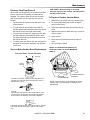
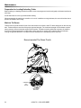
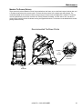
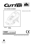
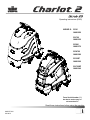
Operating instructions (ENG)
MODELS: CS20
10061250
CSC20
10061330
CSX20
10061370
CSXC20
10061380
CS22SP
10061300
CSC22SP
10061340
From Serial Number (1*)
See Serial number page or
call manufacturer.
Read these instructions before using the machine.
86359770-N
03/18/13
Machine Data Label
Overview
The Chariot Scrubber is a battery powered, stand-on, hard floor scrubber intended for commercial use. The
appliance applies a cleaning solution onto a hard floor, scrubs the floor with brush or pad, and then vacuums the
soiled water back into the recovery tank.
Warranty Registration
Thank you for purchasing a Windsor product. Warranty registration is quick and easy.
Your registration will allow us to serve you better over the lifetime of the product.
To register your product go to :
www.windsorind.com/WarrantyRegistration.aspx
For customer assistance:
1-800-444-7654
2
86359770 - CS20 SCRUBBER
Table of Contents
Machine Data Label . . . . . . . . . . . . . . . . . . . . . . . . . . 2
Table of Contents . . . . . . . . . . . . . . . . . . . . . . . . . . . 3
How To Use This Manual . . . . . . . . . . . . . . . . . . . . . 4
Safety
IMPORTANT SAFETY INSTRUCTIONS . . . . . . . . . 5
HAZARD INTENSITY LEVEL . . . . . . . . . . . . . . . . . . 7
SAFETY LABEL LOCATIONS . . . . . . . . . . . . . . . . . 9
Operations
Technical Specifications . . . . . . . . . . . . . . . . . . . . . 10
How This Machine Works . . . . . . . . . . . . . . . . . . . . 12
Components . . . . . . . . . . . . . . . . . . . . . . . . . . . . . . 13
Drive Controls . . . . . . . . . . . . . . . . . . . . . . . . . . . . . 14
Scrub Controls . . . . . . . . . . . . . . . . . . . . . . . . . . . . 18
Scrub Controls-Squeegee. . . . . . . . . . . . . . . . . . . . 20
Pre-Run Machine Inspection. . . . . . . . . . . . . . . . . . 22
Starting Machine . . . . . . . . . . . . . . . . . . . . . . . . . . . 22
Emergency Stop Procedure . . . . . . . . . . . . . . . . . . 22
Filling Solution Tank . . . . . . . . . . . . . . . . . . . . . . . . 22
Filling Solution Tank (Deluxe) . . . . . . . . . . . . . . . . . 22
Normal Scrubbing . . . . . . . . . . . . . . . . . . . . . . . . . . 23
To Begin Scrubbing . . . . . . . . . . . . . . . . . . . . . . . . 23
To Stop Scrubbing . . . . . . . . . . . . . . . . . . . . . . . . . 24
Double Scrub . . . . . . . . . . . . . . . . . . . . . . . . . . . . . 24
Emptying and Cleaning Tanks . . . . . . . . . . . . . . . . 25
Maintenance
Service Schedule . . . . . . . . . . . . . . . . . . . . . . . . . . 26
Batteries . . . . . . . . . . . . . . . . . . . . . . . . . . . . . . . . . 27
Changing Batteries . . . . . . . . . . . . . . . . . . . . . . . . . 32
Battery Charger Programming . . . . . . . . . . . . . . . . 33
To Remove Squeegee Assembly . . . . . . . . . . . . . . 35
Squeegee Blades-Cylindrical . . . . . . . . . . . . . . . . . 35
Scrub Deck-Disk . . . . . . . . . . . . . . . . . . . . . . . . . . . 36
Scrub Deck-Cylindrical . . . . . . . . . . . . . . . . . . . . . . 36
Scrub Brush-Disk . . . . . . . . . . . . . . . . . . . . . . . . . . 37
Replacing or Installing Scrub Brushes (Disk) . . . . . 38
Replacing or Installing Scrub Brushes (Cylindrical) 39
To Replace Scrub Brush Motor - Disk . . . . . . . . . . 40
Scrub Deck Actuator Removal / Replacement . . . . 42
Circuit Protection. . . . . . . . . . . . . . . . . . . . . . . . . . . 43
Solution . . . . . . . . . . . . . . . . . . . . . . . . . . . . . . . . . . 44
Tank Assembly Removal . . . . . . . . . . . . . . . . . . . . 46
Drive Unit Removal . . . . . . . . . . . . . . . . . . . . . . . . . 47
Vacuum & Float Shutoff . . . . . . . . . . . . . . . . . . . . . 48
Vacuum Motor Carbon Brush Replacement . . . . . . 49
Drive Motor . . . . . . . . . . . . . . . . . . . . . . . . . . . . . . . 50
Drive Chain Tension . . . . . . . . . . . . . . . . . . . . . . . . 50
Transporting . . . . . . . . . . . . . . . . . . . . . . . . . . . . . . 50
Inclines . . . . . . . . . . . . . . . . . . . . . . . . . . . . . . . . . . 51
Machine Tie-Downs . . . . . . . . . . . . . . . . . . . . . . . . 52
Machine Tie-Downs (Deluxe) . . . . . . . . . . . . . . . . . 53
Troubleshooting . . . . . . . . . . . . . . . . . . . . . . . . . . . 54
Battery Discharge Indicator Troubleshooting . . . . . 56
PARTS
Bumper . . . . . . . . . . . . . . . . . . . . . . . . . . . . . . . . . 58
Bumper - Deluxe & Cylindrical . . . . . . . . . . . . . . . 60
Console . . . . . . . . . . . . . . . . . . . . . . . . . . . . . . . . . 62
Control Panel . . . . . . . . . . . . . . . . . . . . . . . . . . . . 64
Decals - Disk . . . . . . . . . . . . . . . . . . . . . . . . . . . . . 68
Decals - Deluxe & Cylindrical . . . . . . . . . . . . . . . . 70
Drive - Lower. . . . . . . . . . . . . . . . . . . . . . . . . . . . . 72
Drive - Chain . . . . . . . . . . . . . . . . . . . . . . . . . . . . . 74
Drive Mounting . . . . . . . . . . . . . . . . . . . . . . . . . . . 76
Frame & Rear Wheels . . . . . . . . . . . . . . . . . . . . . 78
On Board Battery Charger - Disk . . . . . . . . . . . . . 80
On Board Battery Charger - Deluxe & Cylindrical . 82
Pedal Platform . . . . . . . . . . . . . . . . . . . . . . . . . . . 84
Pedal Platform Mounting. . . . . . . . . . . . . . . . . . . . 86
Recovery Tank . . . . . . . . . . . . . . . . . . . . . . . . . . . 88
Scrub Brush - Pad Driver . . . . . . . . . . . . . . . . . . . 90
Scrub Brush Deck - Disk . . . . . . . . . . . . . . . . . . . . 92
Scrub Brush Deck Mounting - Disk . . . . . . . . . . . . 94
Scrub Deck Drive Assembly - Cylindrical . . . . . . . 96
Scrub Deck - Cylindrical . . . . . . . . . . . . . . . . . . . . 98
Scrub Deck Linkage - Cylindrical . . . . . . . . . . . . 100
Scrub Brush Deck Mounting - Cylindrical . . . . . . 102
Scrub Deck Lift . . . . . . . . . . . . . . . . . . . . . . . . . . 104
Solution Tank . . . . . . . . . . . . . . . . . . . . . . . . . . . 106
Solution Tank - Deluxe . . . . . . . . . . . . . . . . . . . . 108
Squeegee . . . . . . . . . . . . . . . . . . . . . . . . . . . . . . 110
Squeegee - Cylindrical . . . . . . . . . . . . . . . . . . . . 112
Squeegee Linkage - Cylindrical . . . . . . . . . . . . . 114
Steering. . . . . . . . . . . . . . . . . . . . . . . . . . . . . . . . 116
Vacuum . . . . . . . . . . . . . . . . . . . . . . . . . . . . . . . . 118
Wiring - Battery . . . . . . . . . . . . . . . . . . . . . . . . . . 120
Wiring Diagram 1 . . . . . . . . . . . . . . . . . . . . . . . . 122
Wiring Diagram 2 . . . . . . . . . . . . . . . . . . . . . . . . 124
Wiring Diagram 3 . . . . . . . . . . . . . . . . . . . . . . . . 126
Wiring Diagram 4 . . . . . . . . . . . . . . . . . . . . . . . . 128
Wiring Diagram 5 . . . . . . . . . . . . . . . . . . . . . . . . 130
Wiring Diagram 6 . . . . . . . . . . . . . . . . . . . . . . . . 132
Wiring Diagram 7 . . . . . . . . . . . . . . . . . . . . . . . . 134
Wiring Diagram 8 . . . . . . . . . . . . . . . . . . . . . . . . 136
Suggested Spare Parts . . . . . . . . . . . . . . . . . . . . 138
Serial Numbers . . . . . . . . . . . . . . . . . . . . . . . . . . 139
86359770 - CS20 SCRUBBER
3
How To Use This Manual
The SAFETY section contains important information
regarding hazardous or unsafe practices of the
machine. Levels of hazards are identified that could
result in product damage, personal injury, or severe
injury resulting in death.
This manual contains the following sections:
•
•
•
•
•
HOW TO USE THIS MANUAL
SAFETY
OPERATIONS
MAINTENANCE
PARTS LIST
The OPERATIONS section is to familiarize the operator
with the operation and function of the machine.
The HOW TO USE THIS MANUAL section will tell you
how to find important information for ordering correct
repair parts.
Parts may be ordered from authorized dealers. When
placing an order for parts, the machine model and
machine serial number are important. Refer to the
MACHINE DATA box which is filled out during the
installation of your machine. The MACHINE DATA box
is located on the inside of the front cover of this manual.
Model:
The MAINTENANCE section contains preventive maintenance to keep the machine and its components in
good working condition. They are listed in this general
order:
•
•
•
•
•
Batteries
Scrub Brush
Squeegee
Service Schedule
Machine Troubleshooting
The PARTS LIST section contains assembled parts
illustrations and corresponding parts list. The parts lists
include a number of columns of information:
Date of Purchase:
Serial Number:
Dealer:
•
Address:
Phone Number:
Sales Representative:
The model and serial number of your machine is
located on the back of the machine.
REF – column refers to the reference number
on the parts illustration.
• PART NO. – column lists the part number for
the part.
• PRV NO. – reference number.
• QTY – column lists the quantity of the part used
in that area of the machine.
• DESCRIPTION – column is a brief description
of the part.
• SERIAL NO. FROM – If this column has an (*)
and a Reference number, see the SERIAL
NUMBERS page in the back of your manual. If
column has two asterisk (**), call manufacturer
for serial number. The serial number indicates
the first machine the part number is applicable
to. The main illustration shows the most current
design of the machine. When a boxed illustration is shown, it displays the older design.
• NOTES – column for information not noted by
the other columns.
NOTE: If a service or option kit is installed on your
machine, be sure to keep the KIT INSTRUCTIONS
which came with the kit. It contains replacement parts
numbers needed for ordering future parts.
NOTE: The manual part number is located on the
lower left corner of the front cover.
4
86359770 - CS20 SCRUBBER
Safety
IMPORTANT SAFETY INSTRUCTIONS
When using this machine, basic precaution
must always be followed, including the following:
READ ALL INSTRUCTIONS BEFORE USING THIS MACHINE.
To reduce the risk of fire, electric shock, or injury:
Use only indoors. Do not use outdoors or expose to rain.
Use only as described in this manual. Use only manufacturer's recommended components and attachments.
If the machine is not working properly, has been dropped, damaged, left outdoors, or dropped into water, return it to
an authorized service center.
Do not operate the machine with any openings blocked. Keep openings free of debris that may reduce airflow.
This machine is not suitable for picking up hazardous dust.
Machine can cause a fire when operating near flammable vapors or materials. Do not operate this machine near
flammable fluids, dust or vapors.
This machine is suitable for commercial use, for example in hotels, schools, hospitals, factories, shops and offices
for more than normal housekeeping purposes.
Maintenance and repairs must be done by qualified personnel.
If foam or liquid comes out of machine, switch off immediately.
Disconnect battery before cleaning or servicing.
Before the machine is discarded, the batteries must be removed and properly disposed of.
Make sure all warning and caution labels are legible and properly attached to the machine.
During operation, attention shall be paid to other persons, especially children.
Before use all covers and doors shall be put in the positions specified in the instructions.
When leaving unattended, secure against unintentional movement.
The machine shall only be operated by instructed and authorized persons.
When leaving unattended, switch off or lock the main power switch to prevent unauthorized use.
Only chemicals recommended by the manufacturer shall be used.
This appliance has been designed for use with the brushes specified by the manufacturer. The fitting of other
brushes may affect its safety.
Do not use on surfaces having a gradient of over 10% (6 degrees).
READ AND SAVE THESE INSTRUCTIONS
86359770 - CS20 SCRUBBER
5
Safety
MESURES DE SÉCURITÉ IMPORTANTES
Lors de l'utilisation d'un appareil à batteries, il est nécessaire de respecter
systématiquement des mesures de sécurité de base, comme suit :
PRENEZ NOTE DE TOUTES CES MESURES AVANT D'UTILISER CETTE MACHINE.
Pour réduire les risques d'incendie, de chocs électriques, ou de blessures :
N'utiliser cette machine qu'en intérieur. Ne jamais l'utiliser à l'extérieur ou dans la pluie.
N'utiliser cette machine que comme décrit dans le présent manuel. N'utiliser que les composants et les accessoires
conseillés par le fabricant.
Lorsque la machine ne fonctionnant pas correctement, a fait l'objet d'une chute ou d'une détérioration, a été laissée
à l'extérieur, est tombée dans l'eau, la retourner au centre de service agréé.
Ne pas opérer la machine lorsque les conduits de ventilation sont bloquées. Débarrasser les débris des conduits,
car ils peuvent réduire l'écoulement d'air.
Cette machine n'est pas adaptée au ramassage de poussières dangereuses
Cette machine peut provoquer un incendie lorsqu'elle est utilisée près de vapeurs ou de matériaux inflammables.
Ne pas l'utiliser près de liquides, de poussières ou de vapeurs inflammables.
Cette machine est destinée à un usage commercial. Elle est recommandée davantage pour les domaines hôtelier,
scolaire, hospitalier, industriel ou pour les bureaux, les chaînes de magasin, que pour un usage domestique
normal.
L'entretien et les réparations de la machine doivent être effectuées par un personnel qualifié.
Si de la mousse ou du liquide sort de la machine, la mettre hors tension immédiatement.
Déconnecter les batteries avant de nettoyer la machine ou de la soumettre à un entretien.
Avant de se débarrasser de la machine, il est nécessaire de retirer les batteries et de les jeter correctement.
S'assurer que toutes les plaques d'avertissement ou de précaution sont lisibles et fixées correctement sur la
machine.
Durant la manoeuvre de la machine, prendre garde aux personnes environnantes et notamment aux enfants.
Avant l'utilisation de la machine, veiller à positionner tous les couvercles et portes comme indiqué dans les instructions.
Lorsque la machine est laissée sans surveillance, s'assurer qu'elle ne se déplace pas de manière accidentelle.
Cette machine ne doit être manoeuvrée que par un personnel expérimenté et qualifié.
Lorsque la machine est laissée sans surveillance, la mettre hors tension ou verrouiller l'interrupteur principal afin
d'empêcher un emploi non autorisé.
Seuls les produits chimiques recommandés par le fabricant doivent être utilisés.
Cette machine a été conçue pour être utilisée avec des brosses spécifiées par le fabricant.
L'utilisation d'autres brosses peut affecter sa sûreté.
N'employez pas sur des surfaces ayant un gradient de plus de 10% (6 degrés).
CONSERVER CES INSTRUCTIONS
6
86359770 - CS20 SCRUBBER
Safety
The following symbols are used throughout this guide as indicated in their descriptions:
HAZARD INTENSITY LEVEL
There are three levels of hazard intensity identified by signal words -WARNING and CAUTION and FOR SAFETY.
The level of hazard intensity is determined by the following definitions:
WARNING - Hazards or unsafe practices which COULD result in severe personal injury or death.
CAUTION - Hazards or unsafe practices which could result in minor personal injury or product or property damage.
FOR SAFETY: To Identify actions which must be followed for safe operation of equipment.
Report machine damage or faulty operation immediately. Do not use the machine if it is not in proper operating
condition. Following is information that signals some potentially dangerous conditions to the operator or the equipment. Read this information carefully. Know when these conditions can exist. Locate all safety devices on the
machine. Please take the necessary steps to train the machine operating personnel.
FOR SAFETY:
DO NOT OPERATE MACHINE:
Unless Trained and Authorized.
Unless Operation Guide is Read and understood.
In Flammable or Explosive areas.
In areas with possible falling objects.
WHEN SERVICING MACHINE:
Avoid moving parts. Do not wear loose clothing; jackets, shirts, or sleeves when working on the machine. Use
Windsor approved replacement parts.
Batteries emit hydrogen gas. Explosion or fire can result. Keep sparks and open flame away. Keep battery
compartment open during charging. Keep sparks and flames away from the batteries. Do not smoke
around batteries.
Disconnect batteries before working on machine. Only qualified personnel should work inside machine.
Always wear eye protection and protective clothing when working on or near batteries. Avoid skin contact
with the acid contained in the batteries.
Never allow metal to lie across battery tops.
86359770 - CS20 SCRUBBER
7
Safety
Les symboles ci-dessous sont utilisés à travers ce manuel comme illustré dans leurs descriptions :
DEGRÉS DE RISQUES EN CAS DE DANGER
Il existe trois degrés de risques identifiés par les termes signalétiques -AVERTISSEMENT et ATTENTION et POUR
VOTRE SÉCURITÉ. Le degré de risque est défini de la manière suivante:
AVERTISSEMENT - Dangers ou méthodes dangereuses qui POURRAIENT provoquer de graves blessures ou
entraîner la mort.
ATTENTION - Dangers ou méthodes dangereuses qui pourraient provoquer des blessures légères ou une détérioration du produit ou des biens immobiliers.
POUR VOTRE SÉCURITÉ: ce signe permet d'identifier les mesures de précaution à prendre pour assurer un bon
fonctionnement du matériel.
Rendre compte immédiatement d'une défaillance ou d'une détérioration de la machine. Ne pas utiliser la machine
si celle-ci ne fonctionne pas correctement. Lire soigneusement les informations ci-dessous signalant certains
dangers potentiels pour l'opérateur de la machine. L'opérateur doit être absolument au courant de ces dangers
potentiels. Localiser tous les dispositifs de sécurité sur la machine. Il est conseillé de prendre les mesures nécessaires pour former le personnel opérateur.
POUR VOTRE SÉCURITÉ:
NE PAS MANOEUVRER LA MACHINE:
Lorsqu'on n'est pas expérimenté ou qualifié.
Lorsque le guide d'utilisation n'est pas été lu ou compris.
Dans des zones inflammables ou explosives.
Dans des zones où des objets peuvent tomber.
LORS DE L'ENTRETIEN DE LA MACHINE:
Éviter les parties amovibles. Ne pas porter de vêtements amples, tels que des vestes, des chemises ou des
vêtements avec manches lors de l'utilisation de la machine. Utiliser les pièces détachées Windsor homologuées.
Les batteries émettent le gaz d'hydrogène. L'explosion ou le feu peut résulter. Étincelles de subsistance et
flamme nue loin. Compartiment de batterie de subsistance ouvert en chargeant. Étincelles et flammes de
subsistance loin des batteries. Ne fumez pas autour des batteries.
Déconnecter les batteries avant de travailler sur la machine. La machine ne doit être confiée qu'à un
personnel qualifié. Porter systématiquement des lunettes et des vêtements de protection lors d'une intervention sur les batteries ou aux alentours. Éviter tout contact de la peau avec l'acide contenu dans les
batteries.
Ne jamais placer d'objets métalliques sur le dessus des batteries.
8
86359770 - CS20 SCRUBBER
Safety
SAFETY LABEL LOCATIONS
These drawings indicate the location of safety labels on the machine. If at any time the labels become illegible,
promptly replace them.
EMPLACEMENT DE L'ÉTIQUETTE DE SÉCURITÉ
REMARQUE : Ces dessins indiquent l'emplacement des étiquettes de sécurité sur la machine. Si, à tout moment,
les étiquettes deviennent illisibles, contactez votre représentant autorisé pour un remplacement rapide.
86244300
PRV NO. 500955
WARNING LABEL
CAUTION
86244310
PRV NO. 500956
CAUTION LABEL
86335010 (2X)
CAUTION LABEL
86252520
PRV NO. 80885
BATTERY
CAUTION
86359770 - CS20 SCRUBBER
9
Operations
Technical Specifications
ITEM
Nominal Power-Disk
Nominal Power-Cylindrical
Rated Voltage
Rated Amperage -Disk
Rated Amperage -Cylindrical
Batteries
Battery Compartment Dimensions
Scrub Brush Motor - Disk Machine
Scrub Brush Motor - Cylindrical Machine
Vacuum Motor
Maximum flow rate of vacuum motor
Maximum suction of vacuum motor
Propelling Motor
Mass (GVW)
Weight empty without batteries - Disk
Weight empty without batteries - Cylindrical
Solution Control
Solution capacity
Recovery capacity
Scrub brush diameter - Disk
Scrub brush length - Cylindrical
Scrub brush pressure - Disk
Scrub brush pressure - Cylindrical
Scrub brush speed - Disk
Scrub brush speed - Cylindrical
Tires
Maximum Speed
Brake
Minimum aisle u-turn width
Maximum rated climb and descent angle
Vibration, hands - Disk
Vibration, feet - Disk
Uncertainty - Disk
Sound pressure level - Disk
Sound power level - Disk
Uncertainty - Disk
Vibration, hands - Cylindrical
Vibration, feet - Cylindrical
Uncertainty - Cylindrical
Sound pressure level - Cylindrical
Sound pressure level - Cylindrical
Uncertainty - Cylindrical
DIMENSION/CAPACITY
1080 W
1512 W
36 Volts DC
30 amps
42 amps
3 X12 Volt 130 AH @ 20 hr. rate
20-1/2 in. x 13 in. x 10 in. tall (330mm x 521mm x 254mm)
1 x .28 HP (209 W)
1 x .8 HP (600 W)
.63 HP (470 W)
72 cfm (33.98 liters per second)
47.3 inches of water (11.7 kPa)
.21 HP (157 W)
726 lbs (330 kg)
209 lbs (96 kg)
255 lbs (116 kg)
Gravity, 1/3 GPM average
10 gal (38 L)
10 gal (38 L)
20 inch (508 mm)
22 inch (559 mm)
50 lbs (222N)
46 lbs (21 kg)
180 rpm
1500 rpm
8 in. (203mm) drive, 6 in. (156mm) rear, polyurethane
2.7 mph (4.3 Km/hour)
Electrical parking brake,sets automatically whenever operator stops.
51in. (1295 mm)
10% (6 degrees)
1.6 m/s²
0.54 m/s²
0.5 m/s²
68.0 dBA
81.1 dBA
3.0 dBA
1.5 m/s²
0.9 m/s²
0.5 m/s²
71.5 dBA
84.7 dBA
3.0 dBA
10
86359770 - CS20 SCRUBBER
Operations
ITEM
Height
Length
Width without squeegee - Disk
Width without squeegee - Cylindrical
Width of squeegee - Disk
Width of squeegee - Cylindrical
Width of scrub path - Disk
Width of scrub path - Cylindrical
MEASURE
51.8 in (1316mm)
44.0 in (1118mm)
23.4 in (594mm)
25.4 in (645mm)
27.2 in (691mm)
29.3 in (744mm)
20 in (508mm)
22 in (559mm)
LENGTH
WIDTH
HEIGHT
This appliance is not intended for use by persons (including children) with reduced physical, sensory or mental
capabilities, or lack of experience and knowledge, unless they have been given supervision or instruction
concerning use of the appliance by a person responsible for their safety. Children should be supervised to ensure
that they do not play with the appliance.
Cet appareil n'est pas prévu à l'usage des personnes (enfants y compris) avec des possibilités physiques, sensorielles ou mentales réduites, ou le manque d'expérience et de connaissance, à moins qu'ils aient été donnés la
surveillance ou l'instruction au sujet de l'utilisation de l'appareil par une personne chargée de leur sûreté. Des
enfants devraient être dirigés pour s'assurer qu'ils ne jouent pas avec l'appareil.
86359770 - CS20 SCRUBBER
11
Operations
How This Machine Works
The Chariot® is a battery powered, self-propelled, hard
floor scrubber intended for commercial use. The
appliance applies a cleaning solution onto a hard floor,
scrubs the floor with a brush, and then vacuums the
soiled water back into the recovery tank.
The machine's primary systems are the solution
system, scrub system, recovery system, and operator
control system.
The function of the solution system is to store cleaning
solution and deliver it to the scrub system. The solution
system consists of the solution tank, strainer, metering
valve and solenoid valve. The solution tank stores
cleaning solution (water and detergent) until it is
delivered to the scrub system. The strainer protects the
valves from debris. The solenoid valve automatically
prevents solution flow unless the scrub brush is turned
on and the machine is being propelled.
The function of the scrub system is to scrub the floor.
The disk scrub system consists of one rotary type disk
scrub brush, motor, scrub deck skirt and lift actuator.
The brush scrubs the floor as the motor drives the
brush. The brush drive hub allows the scrub brush to
follow irregularities and changes in the floor without
loosing contact with the floor. The scrub deck skirt
controls the cleaning solution on the floor so that the
squeegee can pick it up.
The function of the recovery system is to vacuum the
soiled water back into the recovery tank. The recovery
system consists of the squeegee, vacuum motor, float
ball, recovery tank. The squeegee wipes the dirty
solution off the floor as the machine moves forward.
The vacuum motor provides suction to draw the dirty
solution off the floor and into the recovery tank. The
float ball filter protects the vacuum fan from debris and
foam. The recovery tank stores the dirty solution.
The function of the operator control system is to control
the direction and speed of the machine. The directional
control system consists of the direction control drive
reset switch, throttle pedal, emergency stop/brake
switch, steering wheel, propel controller, and drive
wheel. The directional control drive reset switch signals
forward or reverse direction and makes sure the
operator is on the platform before machine will propel.
The controller interprets signals from the throttle pedal
to command the drive wheel to propel or slow the
machine. The steering wheel points the drive wheel in
the direction desired by the operator. The parking brake
automatically engages when the operator stop the
machine. The emergency stop/brake can be used to
hold the machine on slopes.
The cylindrical scrub system consists of two cylindrical
brushes, motor, side squeegees, and lift actuator. The
two counter rotating brushes scrub the floor, driven by a
single motor. The brush deck “floats” with constant
brush pressure. The side squeegees keep the cleaning
solution within the brush deck width, allowing the main
squeegee to pick the solution up.
12
86359770 - CS20 SCRUBBER
Operations
7
3
1
2
10
5
4
6
9
11
12
8
10
Deluxe Disk & Cylindrical
9
Cylindrical
12
Components
1. Drive Control
2. Scrub Controls
3. Control Console
4. Pedal Platform
5. Solution Tank
6. Recovery Tank
7. Recovery Sight Dome
8. Recovery Drain Hose
9. Scrub Deck Skirt
10. Solution Cover
11. Solution Drain Hose/Solution Level Indicator
12. Squeegee
86359770 - CS20 SCRUBBER
13
Operations
Drive Controls
1
8
9
5
2
3
7
6
4
10
14
86359770 - CS20 SCRUBBER
Operations
2. EMERGENCY STOP/BRAKE SWITCH
1. Key Switch
2. Emergency Stop/Brake Switch
3. Directional Control / Drive Reset Switch
4. Throttle Pedal
5. Horn Button
This safety feature is designed to cut all power to
the machine at any time and apply parking brake.
To shut the machine power off, push the
Emergency Stop Switch, this will also engage the
parking brake and cause the machine to stop
immediately.
To reset the machine, rotate the switch clockwise.
3. DIRECTIONAL CONTROL / DRIVE RESET
SWITCH
6. Steering Wheel
7. Speed Control
8. Battery Discharge Indicator
9. Hour Meter
10. Operator Presence Switch
1. KEY SWITCH
Controls the power for machine functions.
To turn the machine power on, rotate key clockwise.
To turn the machine off, rotate key counterclockwise.
When the key is turned on the battery symbol will
flash once and stay on continuously.
This safety feature is designed to ensure safe
engagement of propel drive. Each time the
machine power is turned on, or each time an
operator steps on to the platform, the Drive Reset
Switch must be pushed before machine will propel.
The switch controls the direction of travel of the
vehicle. The lighted arrow on the switch indicates
direction of travel.
To travel forward, press the top of the switch.
To travel in reverse, press the bottom of the switch.
86359770 - CS20 SCRUBBER
15
Operations
4. THROTTLE PEDAL
Controls the speed of the vehicle within the speed control setting selected. Pressing the pedal causes the
machine to travel in the direction selected by the Directional Control Switch.
To increase speed, increase pressure on the pedal.
To decrease speed, decrease pressure on the pedal.
5. HORN BUTTON
The horn is activated by pressing the horn button.
6. STEERING WHEEL
The steering wheel turns the front wheel causing the machine to change direction.
7. SPEED CONTROL
Controls the maximum speed of the machine. There are two settings, slow and fast.
To change speed, rotate the dial to either slow or fast position. The slow position is to the left (counterclockwise), fast to the right (top position).
The throttle pedal will always regulate the speed between 0 and maximum.
SLOW
16
FAST
86359770 - CS20 SCRUBBER
Operations
8. BATTERY DISCHARGE INDICATOR
Indicates the charge level of the batteries.
The indicator will be illuminated if the batteries have a sufficient charge. A slow, continuous flash indicates the
batteries require charging.
The Battery Lockout function will activate when the batteries are low.
Once active, the LED status indicator will begin to flash slowly and the controller will inhibit the scrub motor and
water solenoid. The vacuum and drive remain functional. The “vacuum only” selection (position ‘B’) can be
used to vacuum up any remaining water. Return the unit to the charging station and charge the batteries.
NOTE: Continuing usage may damage the batteries.
When the machine is left overnight with less than a full charge, the display may initially indicate a full charge. It
will also indicate a full charge if the batteries are disconnected, then reconnected. After a few minutes of
operation the indicator will give the correct charge level.
9. HOUR METER
Records the number of hours the machine has been in scrubbing operation. This information is useful in determining when to service the machine.
86359770 - CS20 SCRUBBER
17
Operations
Scrub Controls
1
1. FUNCTION MODE SWITCH
The first two positions are for transport only. See drive controls section.
A1 - Light cleaning
This mode is used for light cleaning. In this mode the machine will propel at fast speed. The ‘floating’ scrub
deck and squeegee is in the down position. The water will flow. Water will automatically shut off in neutral and
restarts when scrubbing is resumed. The vacuum will draw the water into the recovery tank.
A2 - Deep cleaning
This mode is used for deep cleaning. In this mode the machine will propel at a low speed. The ‘floating’ scrub
deck and squeegee is in the down position. The water will flow. Water will automatically shut off in neutral and
restarts when scrubbing is resumed. The vacuum will draw the water into the recovery tank.
18
86359770 - CS20 SCRUBBER
Operations
B - Vacuum only mode
This mode is used for picking up solution only. The brush and water will both be up and off. In this mode the
machine will propel at fast speed. The squeegee is lowered and the vacuum will come on.
C - Double Scrub cleaning
This mode is used for putting down solution and scrubbing without picking it back up. The squeegee is set
manually by connecting the two double scrub support cables. In this mode the machine will propel at a slow
speed. The scrub deck will lower. The solution will flow. The brush and water will shut off when the machine is
in neutral. They will resume when propelling is resumed.
86359770 - CS20 SCRUBBER
19
Operations
Scrub Controls-Squeegee
DISK
4
3
2
5
1
1. Squeegee Latch
2. Squeegee Hose and Tube
3. Squeegee Wheels (3)
4. Double Scrub Support Cable
5. Double Scrub Cable Hook
20
86359770 - CS20 SCRUBBER
Operations
1. Squeegee Latch
The squeegee latch holds the squeegee in place.
2. Squeegee Hose and Tube
The squeegee hose and tube carry the recovered solution to the recovery tank.
3. Squeegee Wheels
The squeegee wheels support the squeegee at the correct height and angle to automatically obtain optimum
suction.
4. Double Scrub Support Cable
The double scrub support cables retain the deck in the double scrub position.
5. Double Scrub Cable Hook
The double scrub cable hook is the connection point for the double scrub support cable.
Since the squeegee is raised and lowered by the scrub deck, the double scrub position is set manually.
CYLINDRICAL
4
1
3
5
2
86359770 - CS20 SCRUBBER
21
Operations
Machine Operation
Pre-Run Machine Inspection
Do a pre-run inspection to find possible problems that
could cause poor performance or lost time from breakdown. Follow the same procedure each time to avoid
missing steps.
NOTE: See maintenance section for pre-run machine
inspection checklist items.
3. Measure the chemical into the solution tank. Liquid
chemicals should be added to the solution tank
after filling with water. Dry chemicals should be
thoroughly mixed before being added into solution
tank. Commercially available, high alkaline floor
cleaners, are suitable for use in the solution system.
NOTE: Read the chemical manufacturers
recommended proportion instructions.
4. Close console and latch rear cover.
Starting Machine
NOTE: Perform pre-run machine check before
operating machine.
FOR SAFETY: Before starting machine, make sure
that all safety devices are in place and operating
properly.
1. The operator should be on the pedal platform. The
throttle pedal must be in the neutral position.
2. Turn the machine power on by turning key switch
clockwise to the “ON” position.
3. Press the Drive Reset Directional Control Switch to
reset and set the intended direction for travel.
4. Press lightly on the throttle pedal with right foot.
Emergency Stop Procedure
Flammable materials can cause an explosion or
fire. Do not use flammable materials in the tanks.
Les matières inflammables peuvent provoquer une
explosion ou un incendie. Ne pas utiliser de
matériaux inflammables dans les réservoirs.
Filling Solution Tank (Deluxe)
FOR SAFETY: Before leaving or servicing machine;
stop on level surface, turn off machine and remove
key.
1. Turn the machine power off.
Push in emergency stop button. This will also engage
the parking brake and cause the machine to stop immediately.
Filling Solution Tank
FOR SAFETY: Before leaving or servicing machine;
stop on level surface, turn off machine and remove
key.
FILL PORT
WITH SCREW CAP
1. Turn the machine power off.
2. Tilt console forward. Push left or right fill port cover
down.Fill the solution tank with clean water, leaving
enough room for the required amount of cleaning
solution. The solution tank capacity filled to fill inlet
is 10 gallons (38 liters). The water must not be hotter than 140° F (60°C) to prevent damage to the
tank.
22
2. Using fill port, fill the solution tank with clean water,
leaving enough room for the required amount of
cleaning solution. The solution tank capacity filled
to fill inlet is 10 gallons (38 liters). The water must
not be hotter than 140° F (60°C) to prevent damage to the tank.
86359770 - CS20 SCRUBBER
Operations
3. Measure the chemical into the solution tank. Liquid
chemicals should be added to the solution tank
after filling with water. Dry chemicals should be
thoroughly mixed before being added into solution
tank. Commercially available, high alkaline floor
cleaners, are suitable for use in the solution system.
To Begin Scrubbing
When operating the machine around people, pay
close attention for unexpected movement. Use
extra caution around children.
Normal Scrubbing
Plan the scrubbing pattern in advance. The longest
track is around the perimeter of the area to be cleaned.
For efficient operation, the runs should be the longest
possible without turning, stopping, or raising or
lowering scrub deck/squeegee.
In order to achieve the best possible results, the area
which is to be cleaned should be swept before scrubbing. Large debris, strings and wire must be removed to
prevent being caught in brushes or squeegee.
If the machine is allowed to stand in neutral with the
scrub deck down, the solutions flow stops and brush
motor stops. If either forward or reverse travel is
selected, the solution flow will continue in the same
setting and the scrub brush motor will continue once
movement of machine begins. Overlap the brush path
and avoid transporting over previously cleaned areas.
Lorsque vous utilisez la machine en présence de
gens, portez une attention particulière aux mouvements inattendus. Soyez plus prudent, surtout en
présence d’enfants.
Flammable liquids and/or reactive metals can
cause explosions or fire! Do not pick up.
Les liquides inflammables et / ou les métaux
réactifs peuvent provoquer des explosions ou un
incendie ! Ne les ramassez pas.
1. Stand on the operator platform. Throttle pedal must
be in neutral position.
2. Turn machine power on.
3. Press the Drive Reset / Directional Control Switch,
selecting the desired travel direction.
4. Position the function control knob to the desired
operation. The scrub deck and squeegee will
lower, and the vacuum will turn on.
5. Drive machine forward to begin scrubbing.The
scrub brush motor will run and solution will flow
when the throttle is depressed.
NOTE: Shut machine off immediately if water or foam
is expelled from the machine. Solution flow is
automatically shut off when brush motor stops. When
brush motor is activated, flow automatically resumes.
86359770 - CS20 SCRUBBER
23
Operations
To Stop Scrubbing
1. Rotate the function knob to either transport position. The brush motor and vacuum will stop and the
scrub deck will rise to the park position, after a preprogrammed delay.
2. Allow the throttle pedal to return to neutral.
3. Turn machine power off.
DOUBLE SCRUB
CABLE
FOR SAFETY: Before leaving or servicing
machine: stop on level surface, turn off machine
and remove key.
DOUBLE SCRUB
HOOK
Double Scrub
Floors which are heavily soiled or have thick accumulations of floor finish may not clean sufficiently with one
pass. In these cases it will be necessary to double
scrub.
Connect the Double Scrub Cables to the squeegee.
Rotate the knob to the double scrub position.
Cylindrical Machine
NOTE: The deck and squeegee must be in the up
position to hook the cables.
To support the squeegee off the floor for double scrub,
pull the support cables down, one side at a time, and
connect to the hook on the squeegee while lifting and
tilting the squeegee upward.
To collect the solution and complete the Double Scrub
operation, release both squeegee cable and turn the
function knob to one of the normal scrubbing modes.
DOUBLE SCRUB
CABLE
DOUBLE SCRUB HOOK
Disk Machine
24
86359770 - CS20 SCRUBBER
Operations
Emptying and Cleaning Tanks
Solution Tank
1. Park the machine next to a floor drain. Drain hoses
are at the rear of the machine.
1. Pull the solution drain hose from its mounting
pocket. Lower hose in direction of drain.
2. Turn the machine power off.
2. Open the control console.
Recovery Tank
1. Pull the recovery drain hose from the mounting
pocket. Lift cap, pinch hose then lower hose in
direction of the drain. Do not stand in front of end of
hose. Recovered solution will come out with force.
3. Flush the solution tank out with clean water and
run several gallons of clean water through systems. Do not use water hotter than 140°F (60°C) to
clean tank. Damage may occur.
NOTE: Never allow solution to remain in tank.
Damage to tank, seals and valves could occur.
2. To flush the recovery tank, lift the control console to
access the recovery tank. Do not use water hotter
than 140°F (60°C) to clean tank. Damage may
occur.
3. Clean debris from sight dome and cover surface.
4. Clean off the float shut-off screen and inspect for
free movement of float.
5. Replace the drain cap and secure drain hose.
6. If machine is to be stored, tilt the recovery tank
back and prop the console up, partially opening
each.
RECOVERY
DRAIN HOSE
SOLUTION
DRAIN HOSE
STORAGE POSITION
86359770 - CS20 SCRUBBER
25
Maintenance
Service Schedule
BEFORE EACH
WORK PERIOD
MAINTENANCE
Check water level of batteries after charging; add
distilled water if necessary. (Wet cell only)
Visually check for damaged or worn tires.
Check brush or pad for proper installation.
Check vacuum hose connections.
Check that squeegee is securely attached.
Check for securely attached drain hoses, plug and cap.
Check pedal, brake and steering for proper operation.
Clean out recovery tank.
Clean and inspect float shutoff.
Clean out solution tank.
Clean and inspect solution filter strainer.
Run vacuum motor to dry.
Clean brush or pad and check wear.
Clean squeegee blades and check wear.
Clean outside of tanks, check for damage.
Store with console cover propped open.
Charge batteries if needed.
Clean off top of batteries.
Check battery cells with hydrometer. (Wet cell only)
Inspect scrub deck skirt.
Clean solution strainer inside tank.
Check battery connections are tight.
Clean battery cases and battery compartment.
Check parking brake.
Clean pivot points on squeegee and scrub deck.
Check all motors for carbon brush wear.
Check motor commutators.
Check steering chain tension.
Check drive chain tension.
26
AFTER EACH
50 100 200
WORK PERIOD HRS HRS HRS
*
*
*
*
*
*
*
86359770 - CS20 SCRUBBER
*
*
*
*
*
*
*
*
*
*
*
*
*
*
*
*
*
*
*
*
*
*
Maintenance
Batteries
1
4
3
2
5
1. Cover Retainer Latch
2. Rear Cover
3. Battery Connector-Machine
4. Batteries
5. Battery Tray
86359770 - CS20 SCRUBBER
27
Maintenance
Batteries (Wet Cell)
The batteries provide the power to operate the
machine. The batteries require regular maintenance to
keep them operating at peak efficiency.
The machine batteries will hold their charge for long
periods of time, but they can only be charged a certain
number of times. To get the greatest life from the
batteries, charge them when their charge level reaches
25% of a full charge. Use a hydrometer to check the
charge level.
Do not allow the batteries to remain in a discharged
condition for any length of time. Never expose a
discharged battery to temperatures below freezing.
Discharged batteries will freeze causing cracked
cases. Do not operate the machine if the batteries are
in poor condition or if they have a charge level below
25% (specific gravity below 1.155).
Keep all metallic objects off the top of the batteries, as
they may cause a short circuit. Replace worn or
damaged cables and terminals.
Check the electrolyte level in each battery cell before
and after charging the batteries. Never add acid to the
batteries, use distilled water. Do not allow water level to
fall below the battery plates. Portions of plates exposed
to air will be destroyed. Do not overfill. Keep plugs
firmly in place at all times.
Not all batteries require maintenance. AGM
batteries are maintenance free. Do not attempt to
remove sealed caps from AGM batteries. Warranty
is void if caps are removed from AGM battery.
L’entretien n’est pas nécessaire pour toutes les
batteries. Les batteries AGM ne nécessitent pas
d’entretien. N'essayez pas d'enlever les bouchons
scellés des batteries AGM. La garantie est annulée
si les bouchons sont retirés des batteries AGM.
28
86359770 - CS20 SCRUBBER
Maintenance
Battery Maintenance
When servicing machine, avoid contact with
battery acid.
Lors de l'entretien de la machine, évitez tout
contact avec l'acide de batterie.
Batteries emit hydrogen gas. Explosion or fire can
result. Keep sparks and open flame away. Keep
covers open when charging.
Les batteries émettent du gaz hydrogène. Une
explosion ou un incendie peut en résulter.
Maintenez les étincelles et les flammes nues à
l’écart. Gardez les carters ouverts lors du chargement.
1. When cleaning the batteries, use a solution of
baking soda and water. Do not allow the cleaning
fluid to enter the battery cells, electrolyte will be
neutralized.
2. Maintain the proper electrolyte level in each battery
cell. If a cell should accidentally overflow, clean
immediately.
3. Wipe off the top of the batteries at least once a
week.
4. Test battery condition with a hydrometer at least
once a week.
5. Ensure that all connections are tight and all
corrosion removed.
6. Every 4 to 6 months, remove the batteries from the
machine and clean the battery cases and battery
compartment.
Wear eye protection and protective clothing when
working with batteries.
Portez des lunettes de protection et des vêtements
de protection lorsque vous travaillez avec des
batteries.
Charge batteries in a well ventilated area.
Chargez les batteries dans un endroit bien ventilé.
86359770 - CS20 SCRUBBER
29
Maintenance
Checking Battery Specific Gravity
Use a hydrometer to check the battery specific gravity.
CHECKING GRAVITY
a. Hydrometer Battery
b. Battery
NOTE: Do not take readings immediately after adding
distilled water, if the water and acid are not thoroughly
mixed, the reading may not be accurate.
Check the hydrometer readings against this chart.
SPECIFIC GRAVITY
@ 80° F (27°C)
1.265
1.225
1.190
1.155
1.120
BATTERY CONDITION
100% CHARGED
75% CHARGED
50% CHARGED
25% CHARGED
DISCHARGED
NOTE: If the readings are taken when the battery
electrolyte is any temperature other than 80°F (27°C),
the reading must be temperature corrected.
To find the corrected specific gravity reading when the
temperature of the battery electrolyte is other than 80°F
(27°C): Add (+) to the specific gravity reading 0.004 (4
points), for each 10°F (6°C) above 80° (27°C). Subtract
(-) from the specific reading 0.004 (4 points), for each
10°F (6°C) below 80°F (27°C).
30
86359770 - CS20 SCRUBBER
Maintenance
Charging Batteries
Use a 36 volt, 20 amp maximum output DC charger
which will automatically shut off when the batteries are
fully charged.
When servicing machine, avoid contact with
battery acid.
Lors de l'entretien de la machine, évitez tout
contact avec l'acide de batterie.
Batteries emit hydrogen gas. Explosion or fire can
result. Keep sparks and open flame away. Keep
covers open when charging.
Les batteries émettent du gaz hydrogène. Une
explosion ou un incendie peut en résulter.
Maintenez les étincelles et les flammes nues à
l’écart. Gardez les carters ouverts lors du chargement.
Wear eye protection and protective clothing when
working with batteries.
Portez des lunettes de protection et des vêtements
de protection lorsque vous travaillez avec des
batteries.
1. Stop the machine in a clean, well ventilated area
next to the charger.
2. Turn “OFF” machine.
FOR SAFETY: Before leaving or servicing machine;
stop on level surface, turn off machine and remove
key.
3. Open rear cover to expose batteries, unplug
batteries from machine.
Batteries emit hydrogen gas. Explosion or fire can
result. Keep sparks and open flame away. Keep
covers open when charging.
Les batteries émettent du gaz hydrogène. Une
explosion ou un incendie peut en résulter.
Maintenez les étincelles et les flammes nues à
l’écart. Gardez les carters ouverts lors du chargement.
4. Check the electrolyte level in each battery cell.
Before charging, add just enough distilled water to
cover the plates. After charging is complete, add
just enough distilled water to bring up the level to
the indicator ring. If the water level is too high
before charging, normal expansion rate of the electrolyte may cause an overflow resulting in a loss of
battery acid balance and damage the machine.
Charge batteries in a well ventilated area.
Chargez les batteries dans un endroit bien ventilé.
86359770 - CS20 SCRUBBER
31
Maintenance
5. Replace the battery caps, and leave them in place
while charging.
6. Disconnect main positive lead and secure cable
terminals away from batteries.
6. Unplug the battery connector from the machine.
7. Loosen both terminals on each jumper cable and
remove one at a time.
FOR SAFETY: When charging, connect the
charger to the batteries before connecting the
charger to the AC wall outlet. Never connect the
charger to the AC wall outlet first. Hazardous
sparks may result.
7. Plug the charger connector into the battery
connector. Connect the charger AC plug to a wall
outlet. The charger gauge should indicate that the
batteries are charging.
8. When the batteries are fully charged, disconnect
the charger from the AC wall outlet, then disconnect the charger from the batteries.
9. Connect the batteries to the machine connector.
10. Check the electrolyte level. It should be up to the
indicator ring. If necessary, add distilled water.
11. Install the rear cover.
8. Prepare a suitable site to place the batteries.
Attach suitable battery lifting device and lift
batteries from the machine. Batteries are a
potential environmental hazard. Consult your
battery suppler for safe disposal methods.
Fixez le dispositif de levage de batterie approprié et
levez les batteries de la machine. Les batteries
constituent un danger potentiel pour l'environnement. Consultez le fournisseur de votre
batterie pour connaître les méthodes d'élimination
sûres.
BLACK
Changing Batteries
RED
Stop the machine in a clean area next to the charger.
Turn off machine.
FOR SAFETY: Before leaving or servicing the
machine; stop on level surface, turn off machine
and remove key.
BLACK
RED
BLACK
RED
1. Open the console cover.
2. Tilt the rear cover/recovery tank back. The rear
cover/recovery tank can also be removed for better
access.
3. If equipped with optional on board charger, tilt
charger mount to rear of machine.
4. Disconnect battery pack from machine.
5. Use the proper size open end wrench to disconnect main ground wire first and secure cable
terminal away from batteries.
REAR OF MACHINE
32
86359770 - CS20 SCRUBBER
Maintenance
Battery Charger Programming
NOTE: For machines equipped with optional onboard charger. When replacing batteries, charger
programming changes may be required. If replacing
batteries with same type, (e.g. maintenance free
batteries with maintenance free) no programming is
required. When batteries with different type
(e.g.maintenance free with wet cell), programming
changes are required. Failure to make programming
changes may lead to reduced battery life.
Switching From Wet Cell to Maintenance
Free Batteries
Program charger from normal mode (red LED flashes)
to alternate mode (Red and green LED’s flash):
1. Disconnect battery charger from outlet.
2. Connect (+) wire from EZlamp to (+) charger
battery cable.
Switching From Maintenance Free to Wet
Cell Batteries
Program charger from alternate mode (Red and green
LED’s flash) to normal mode (red LED flashes):
1. Disconnect battery charger from outlet.
2. Connect (+) wire from EZlamp to (+) charger
battery cable.
3. Connect AC cord to outlet. Red LED should be on.
NOTE: If Red LED light does not flash, repeat steps 1
and 2.
4. Wait 5 seconds, disconnect wires and unplug
charger.
5. Programming is complete.
NOTE: Battery Charger must be approved to
60335-2-29 standard.
3. Connect AC cord to outlet. All LED’s should be on.
NOTE: If Red and green LED’s do not flash, repeat
steps 1 and 2.
4. Wait 5 seconds, disconnect wires and unplug
charger.
5. Programming is complete.
86359770 - CS20 SCRUBBER
33
Maintenance
To Remove Squeegee Assembly
1. With the squeegee in the up position, turn key
switch “OFF”.
2. Disconnect vacuum hose from squeegee and
squeeze the squeegee retaining latch.
3. Pull squeegee assembly from the squeegee arm.
4. Inspect or repair as necessary and reinstall.
To Replace or Rotate Squeegee Blades
1. Squeegee
Retainer Latch
DISK
2 1
2. Squeegee
Squeegee Blades - Disk
The front squeegee blade allows solution to pass
through channels in the blade into the squeegee
assembly while maintaining vacuum to provide lift. The
front blade has four wear surfaces and can be rotated
for extended life. The front blade should not require
regular replacement under normal use.
The rear blade wipes the floor to a near dry condition. It
is important the rear blade be in good condition to
properly do its job. As with the front, each squeegee
blade assembly has four wear surfaces for extended
service.
Check both the front and rear squeegee blades for
damage and wear each day in the pre-run check.
Change the front blade if it is torn or has an uneven
edge. Change the rear blade if it is less than half the
original thickness.
34
1. With the squeegee in the up position, turn key
switch “OFF”.
FOR SAFETY: Before leaving or servicing machine;
stop on level surface, turn off machine and remove
key.
2. Remove the squeegee assembly from the
machine.
3. Unscrew each of the four (4) knobs until they are
nearly removed from the squeegee assembly.
Grasp the squeegee assembly and push on the
knobs to remove the blade retainer.
Remove the knobs and pull the blade retainer out.
Rotate the squeegee blade to new edge position or
replace as required. Each blade has four (4) new
edge positions.
4. Pull the blades off the retainer.
To reinstall the blades, hook the blades over the
pins on the retainer plate.
5. Lower the retainer with blades back in position in
the squeegee assembly and install the knobs.
86359770 - CS20 SCRUBBER
Maintenance
To Replace or Rotate Squeegee Blades
1. With the squeegee in the up position, turn key
switch “OFF”.
FOR SAFETY: Before leaving or servicing machine;
stop on level surface, turn off machine and remove
key.
2. Remove the squeegee assembly from the
machine.
1
1. Squeegee
Retainer Latch
2
2. Squeegee
CYLINDRICAL
3. Unscrew two yellow thumb screws. Remove
bumper wheels and plastic end caps.
4. Slide squeegee blade(s) out the end of the
squeegee.
5. Reverse procedure to install new blades.
Squeegee Blades-Cylindrical
Squeegee Adjustment
The front squeegee blade allows solution to pass
through channels in the blade into the squeegee
assembly while maintaining vacuum to provide lift. The
front blade has two (2) wear surfaces and can be
rotated for extended life. The front blade should not
require regular replacement under normal use.
Adjust squeegees to improve contact between
squeegees and floor during cleaning modes, and
ensure clearance when in transport mode.
The rear blade wipes the floor to a near dry condition. It
is important the rear blade be in good condition to
properly do its job. As with the front, each squeegee
blade assembly has two (2) wear surfaces for extended
service.
Check both the front and rear squeegee blades for
damage and wear each day in the pre-run check.
Change the front blade if it is torn or has an uneven
edge. Change the rear blade if it is less than half the
original thickness.
To Remove Squeegee Assembly
1. With the squeegee in the up position, turn key
switch “OFF”.
1. Turn machine on and put rotary switch into function
mode B (Vacuum only mode). Let deck position
itself.
2. Turn machine off.
3. Loosen nut that secures the Deck Adjustment
Bracket to the Squeegee Mount Bracket, to allow
the squeegee assembly to rest its wheels on the
floor.
4. Position deck adjustment bracket so that there is
approximately 1/8” of gap between the deck adjustment bracket and the deck lift bar and tighten nut.
5. Turn machine on and assure squeegee lifts off of
ground when in transport mode, and is on the
ground in vacuum only mode.
Deck Lift Bar
2. Disconnect vacuum hose from squeegee and
squeeze the squeegee retaining latch.
3. Pull squeegee assembly from the squeegee arm.
4. Inspect or repair as necessary and reinstall.
Deck Adjustment Bracket
1/8" Squeegee Mount
Bracket
Squeegee Assembly
Floor
86359770 - CS20 SCRUBBER
35
Maintenance
3
2
1
3
DISK
2
1
CYLINDRICAL
Scrub Deck-Disk
Scrub Deck-Cylindrical
1. Scrub Deck Side
1. Scrub Deck Side Squeegee
2. Scrub Brush Motor
2. Scrub Brush Motor
3. Scrub Deck Lift Actuator
3. Scrub Deck Lift Actuator
36
86359770 - CS20 SCRUBBER
Maintenance
Scrub Brush-Disk
There are different types of brushes available to cover
applications from cleaning heavily soiled floors to
polishing. A pad driver is also available to take
advantage of the many cleaning pads on the market.
Please refer to the following to assist in selecting the
proper brush or pad for the work at hand.
Finished Floors
Polypropylene is a general-purpose scrub brush with
stiff bristles. Polypropylene works well for maintaining
routed tile floors.
Nylon bristles are used in a variety of applications on
coated or uncoated surfaces.
White Pads (Polishing) are used for dry polishing to
achieve a high-gloss appearance, or surface washing
on highly polished or burnished floors.
Red Pads (Buffing) are used for light-duty scrubbing.
When used with a mild detergent they will provide
surface cleaning without removing the finish.
Blue Pads (scrubbing) are used for heavy scrubbing
and light top scrubbing. The blue pads remove black
marks, stains and dirt. The blue pad may also remove
some floor finish.
Black pads (top scrubbing) are used to remove ground
in soil and the top layers of floor finish to prepare for
recoating.
The scrub brushes should be checked before each
days work for wire, string, wear and damage.
Scrub Brush-Cylindrical
There are different types of brushes available to cover
applications from cleaning heavily soiled floors to
polishing.
White (Soft)
Orange (Hi/Lo)
Red (Medium)
Green (Hard)
86359770 - CS20 SCRUBBER
37
Maintenance
Replacing or Installing Scrub Brushes
(Disk)
FOR SAFETY: Before leaving or servicing the
machine; stop on level surface, turn OFF machine
and remove key.
1. Turn machine power off.
2. Open access cover on deck shroud.
4. Remove brush/pad from holder and replace with
new brush/pad.
5. To reinstall, lift deck shroud upward as shown.
Center the brush/pad driver under the brush drive
hub.
Raise brush/pad until it contacts brush driver
assembly. Turn clockwise until release lever plate
locks into position.
3. Locate release lever, press release lever towards
front of machine to release brush pad. The pad will
drop down when released. Lift deck shroud up and
slide brush/pad assembly out.
6. Check that release lever/plate is completely closed
and pad/brush is securely attached.
NOTE: Damage to driver or brush could occur if not
securely attached.
38
86359770 - CS20 SCRUBBER
Maintenance
Replacing or Installing Scrub Brushes
(Cylindrical)
FOR SAFETY: Before leaving or servicing the
machine; stop on level surface, turn OFF machine
and remove key.
4. Slide new brushes into receptacle at far side of
deck, lift upward and snap into position. Ensure
brushes are secure.
1. Turn machine power off.
2. From right side of machine, lift squeegee latch and
swing side squeegee outward to access brushes.
Squeegee Latch
5. Close side squeegee and latch securely.
3. Press brush release. Brushes will drop downward.
Remove old brushes.
86359770 - CS20 SCRUBBER
39
Maintenance
Do not use a pressure washer to clean around the brush motors. Use tap pressure only.
N’utilisez pas de nettoyeur haute pression pour nettoyer autour des moteurs des brosses. Utilisez
seulement la pression du robinet.
To Replace Scrub Brush Motor - Disk
With the scrub deck in the lowered position, disconnect brush motor wiring connector from harness.
1. Disconnect the two(2) connectors from solenoid valve.
2. Remove squeegee.
3. Remove front bumper.
4. Remove four (4) front bolts connecting deck lifting arms to front of machine.
5. Lift deck and side deck lift brackets off actuator lifting pin.
6. Slide deck out from under machine on right side, orientation is determined from operators view.
7. Remove brush/pad.
8. Remove driver.
9. Remove three (3) screws securing brush motor to deck.
10. Remove brush motor.
11. Reverse steps to install.
40
86359770 - CS20 SCRUBBER
Maintenance
Do not use a pressure washer to clean around the brush motors. Use tap pressure only.
N’utilisez pas de nettoyeur haute pression pour nettoyer autour des moteurs des brosses. Utilisez
seulement la pression du robinet.
To Replace Scrub Brush Motor-Cylindrical
1. Lower scrub deck using selector knob. Turn off key in down position.
2. Disconnect the two connectors from solenoid valve.
3. Remove squeegee assembly.
4. Remove front bumper, 2 bolts.
5. Remove four front bolts connecting deck lifting arms to front of machine.
6. Remove actuator lifting pin and washers.
7. Remove solenoid valve and cover, 2 screws.
8. Disconnect motor plug from harness.
9. Slide deck out from under machine on right side, orientation is determined from operators view.
10. Remove metal cover over motor by removing 10 screws mounting to deck.
11. Remove screws mounting motor to drive housing and remove motor.
12. Reverse steps to install.
86359770 - CS20 SCRUBBER
41
Maintenance
Scrub Deck Actuator Removal / Replacement
FOR SAFETY: Before leaving or servicing machine, stop on a level surface. Turn off machine.
1. Support deck under pad driver so that actuator pins can be removed.
2. Remove bumper screws (2).
3. Remove front battery.
4. Pull steering shaft.
5. Disconnect actuator from wiring harness.
6. From the underside of the machine, remove lower lifting pin from actuator.
7. Remove clevis pin from actuator upper bracket.
8. Lift actuator upward and free from machine.
9. Reverse steps to install.
42
86359770 - CS20 SCRUBBER
Maintenance
Circuit Protection
CIRCUIT BREAKERS
Circuit Breakers
Circuit breakers interrupt the flow of power in the event of an electrical overload. When a circuit breaker is tripped,
reset it by pressing the exposed button. If a circuit breaker continues to trip, the cause of the electrical overload
should be found and corrected.
1.5 Amp protects the brush deck lift actuator, horn & controller.
18 Amp protects the vacuum motor.
12 Amp protects the brush motor - Disk.
25 Amp protects the brush motor - Cylindrical.
86359770 - CS20 SCRUBBER
43
Maintenance
Solution
2
1
3
CYLINDRICAL
3
1. Solution Strainer-Coarse
2. Shut-off Valve
3. Solenoid Valve
44
86359770 - CS20 SCRUBBER
Maintenance
1. SOLUTION STRAINER
Located in bottom of tank. The strainer protects the ball valve and solenoid valve from debris. If the ball valve
and solenoid valve are not working, then check the strainer for debris.
Drain the solution tank.
Reach down to the strainer and remove debris. If the strainer can not be cleaned in place remove strainer.
To remove the strainer, rotate the strainer counterclockwise.
Clean out the debris from wire mesh and re-assemble.
2. SHUT-OFF FLOW VALVE
Located below the solution tank on the right side. If no flow, check lever position.
Horizontal is no flow.
Up is maximum flow.
If clogged, in the maximum position, unscrew fittings, inspect and clean if needed.
3. SOLENOID VALVE
The solenoid valve shuts off solution flow to scrub deck whenever scrubbing stops.
The solenoid valve is mounted on the front of the scrub deck, on left side.
Shut off manual water supply valve on right side of machine.
Disconnect the two (2) spade connections.
The solenoid valve snaps into place, rock the solenoid valve back and forth while lifting to free it.
Remove valve from supply hose.
86359770 - CS20 SCRUBBER
45
Maintenance
Tank Assembly Removal
In order to access the frame or drive components, the
entire tank/console cover assembly can be removed as
a single unit.
Tank Removal:
1. Open the console cover.
2. Tilt the recovery tank back until it stops on the
lanyard.
3. Remove the recovery tank vacuum hose from its
connection at the rear cross member.
4. Tilt the recover tank slightly forward and disconnect
the lanyard. Lean the recovery tank back until it
contacts the floor. Lift the tank and back panel from
the hinge pin and set aside.
9. Remove the battery cable connection from the rear
cross member.
10. Close the console cover.
11. Locate the solution solenoid valve on the left side
of the scrub deck. Remove two electrical wires
from the valve. The wires are interchangeable. Lift
the valve out of its mount pocket and move the
valve and connected hose over to the right side of
the machine. It is not necessary to remove the
valve or hose from the solution tank.
12. Remove the bumper. One mounting bolt per side is
located just above the tip pads on the inside.
13. Remove 5 bolts holding the tank in place.
14. The tank assembly can now be lifted off the
chassis and set aside.
5. Disconnect the squeegee vacuum hose from the
connection at the rear cross member.
15. Support the tank assembly so that the weight of it
is not resting on the solution valve plumbing.
6. Grasp the lower end of the flexible steering shaft
and pull it straight up until it is disengaged with the
hex steering shaft. Place the loose end into one of
the fill ports.
16. The lower half of the electrical connectors can now
be easily placed on to their support plate.
7. Remove the cover and gasket at the steering shaft
area.
17. Reverse the process for reassembly. Refer to the
electrical diagrams for connections.
8. Disconnect the electrical plugs located just forward
of the battery tray. To disconnect, lift the plugs off of
their mounting plate, locate and depress the lock
tab and pull the connectors apart. Replace the
lower half of the connectors on to the support plate
after the tank assembly has been removed.
46
86359770 - CS20 SCRUBBER
Maintenance
Drive Unit Removal
1. Remove tank assembly.
2. Pull the brake and drive electrical connectors off of
their support plate.
3. Remove the P-clamp holding the cable.
4. Lift the chain cover plate off of the motor.
5. Support the chassis on the tip pads so that the
front wheel is 10 inches off the floor.
6. Locate and remove two mounting nuts and remove
the drive unit from below.
7. To reinstall, reverse the process.
8. Note the small tab at the front of the drive unit
frame should line-up with the notch in the mating
plate.
86359770 - CS20 SCRUBBER
47
Maintenance
Vacuum & Float Shutoff
2
1
1. Recovery Tank Float Shut-off
2. Vacuum Motor
48
86359770 - CS20 SCRUBBER
Maintenance
Recovery Tank Float Shut-off
FOR SAFETY: Before leaving or servicing
machine, stop on a level surface, turn off machine
and disconnect power.
When water is no longer being vacuumed from the floor
and the vacuum fan is operating, the ball float has
engaged. The vacuum motor will not vacuum water
with recovery tank full. The recovery tank must be
drained.
To Repair or Replace Vacuum Motor
1. The float shut-off screen can be cleaned in or out
of the machine.
2. Tip control panel back from console to expose
vacuum motor wires.
2. To clean the float shut-off while it is inside the
machine wipe material off screen then rinse. Check
that the ball is also clean and moves freely.
3. Disconnect electrical connector from the vacuum
motor.
3. To remove the float shut-off, grasp the screen with
one hand and the connected tube with the other.
Tilt and pull the float screen assembly to pull it off
the barb on the tube.
4. To install, place one hand on the tube, and then tilt
and push the float screen assembly over the barb
on the tube.
Vacuum Motor Carbon Brush Replacement
1. Remove four (4) screws from top of control panel.
4. Replace control panel, attach with one (1) screw to
secure in place.
5. Open console.
6. Remove three (3) screws that secure vacuum
motor.
7. Reverse steps to install.
MOUNT .80" FROM SEALING SURFACE OF
CONSOLE TO THE TOP OF THE MOUNTING
TABS (3).
Vacuum Motor Carbon Brushes
End Cap
Carbon
Brushes
.80"
If armature commutator is grooved, extremely pitted or not
concentric, the motor will need to be replaced or sent to a
qualified service center.
VACUUM
MOUNTING TAB
CONSOLE SEALING
SURFACE
NOTE: If vacuum motor is not mounted as shown,
vacuum may not seal properly, resulting in poor
performance.
Inportant:
These brushes wear quicker as the length shortens due to
increased heat. Spring inside brush housing will damage
motor if brushes are allowed to wear away completely.
3 [9.5mm]
8
Periodically check the length of the carbon brushes. Replace
both carbon brushes when either is less tan 3/8" (9.5mm)
long.
86359770 - CS20 SCRUBBER
49
Maintenance
Drive Motor
Drive Chain Tension
Drive Motor Carbon Brush Replacement
The drive chain should deflect about 1/4 inch on either
side of the loop when the opposite side is tight.
To adjust chain tension:
Do not use a pressure washer to clean around the
motors. Use tap pressure only.
N’utilisez pas de nettoyeur haute pression pour
nettoyer autour des moteurs des brosses. Utilisez
seulement la pression du robinet.
FOR SAFETY: Before leaving or servicing
machine, stop on a level surface, turn off machine
and remove motor carbon brushes.
1. Remove bumper.
2. Loosen five (5) 10mm screws that hold the drive
gear motor and slide the gear motor up until the
chain tension is correct. Retighten the five (5)
mounting bolts.
3. Reinstall the bumper.
Transporting
Pushing Machine
This machine is equipped with a drive gear engagement/disengagement lever.
1. Open the console cover.
2. Tilt the recovery tank back until it stops on the
lanyard.
3. Grasp the lower end of the flexible steering shaft
and pull it straight up until it is disengaged with the
hex steering shaft. Place the loose end into one of
the fill ports.
4. Remove the cover and gasket at the steering shaft
area.
5. Grasp the drive wheel by reaching under the front
bumper and turn it to near the left steering stop.
6. The drive motor carbon brushes are located under
screw caps. The caps are accessible by gently
moving the harness aside.
The brake automatically engages and keeps the
machine from moving whenever the operator stops the
machine.
The drive gear can be disengaged so the machine can
be pushed or towed (slowly).
When the drive gear is disengaged the machine cannot
be driven.
NOTE: Front bumper removed for clarity and to show
access to lever.
Lever access
Turn wheel to left and reach up under bumper and steel
bracket.
7. Rotate the drive wheel to near the right hand stop
to access the right side carbon brush.
8. Replace the gasket and cover, set the drive wheel
straight ahead, set the steering wheel straight
ahead, and gently align the steering shaft coupling
and slide onto the lower shaft.
9. Slowly close the cover and make sure the shaft
slides without binding.
50
86359770 - CS20 SCRUBBER
Maintenance
Drive gear engaged
Inclines
Machine can be driven.
When navigating an incline the machine may come to a
stop. Turn the machine off. Wait 5 minutes and start the
machine and proceed up the incline.
Rotate lever firmly in direction of arrow.
Overheating may occur if you do not wait the full 5
minutes.
Une surchauffe peut se produire si vous n'attendez
pas les 5 minutes complètes.
Drive gear disengaged
Machine can be pushed or towed (slowly).
When disengaged the machine rolls easily. Disengage
on a level surface.
Rotate lever firmly in direction of arrow.
86359770 - CS20 SCRUBBER
51
Maintenance
Preparation for Loading/Unloading Trailer
Before loading or unloading machine from trailer, remove squeegee and scrub brush (pad) to eliminate interference
with ramp.
Scrub head must be in the up position before loading.
When transporting the machine on a trailer or in a truck, in addition to using tie-downs, be sure to block the tires to
prevent the machine from rolling.
Machine Tie-Downs
There are two tie points located in front of the rear wheels on the frame, and a Tie-down wrap point on the recovery
tank. Tie-down devices must be of the proper type and strength. The combined strength of all tie-downs must be
strong enough to lift two times the weight of the machine. Tie-downs must be positioned to prevent the machine
from moving forward, backward, or either side to side. Use all four corners of the machine with the tie-downs
running out opposite directions. Tie-downs must be attached to the transporting vehicle securely.
Recommended Tie-Down Points
CONNECT
AT
FRAME
VIEW FROM
BOTTOM
52
86359770 - CS20 SCRUBBER
Maintenance
Machine Tie-Downs (Deluxe)
There are two tie points located in front of the rear wheels on the frame, one on the front bumper tie-down bar, and
a Tie-down wrap point on the recovery tank. Tie-down devices must be of the proper type and strength. The
combined strength of all tie-downs must be strong enough to lift two times the weight of the machine. Tie-downs
must be positioned to prevent the machine from moving forward, backward, or either side to side. Use all four
corners of the machine with the tie-downs running out opposite directions. Tie-downs must be attached to the transporting vehicle securely.
Recommended Tie-Down Points
CONNECT
AT
FRAME
VIEW FROM
BOTTOM
CONNECT
AT
BUMPER
86359770 - CS20 SCRUBBER
53
Maintenance
Troubleshooting
PROBLEM
No machine function
No power to machine
Little or no propel
CAUSE
Console lid is open
Battery disconnected
Emergency shut-off activated
Battery cables corroded
Faulty key switch
Batteries not plugged in
On Board charger plugged in
Low battery charge
Tripped circuit breaker
Drive Lever disengaged
SOLUTION
Close console lid
Check all battery cable connections
Reset
Clean connections
Replace switch
Plug batteries in
Un-plug and stow cord
Charge batteries
Reset controller circuit breaker
Controller limits motor amperage. Allow
unit to cool down for several minutes.
Remove obstacle or push machine away
from obstacle
Allow cool down period
Check wires and connections from
controller to motor
Check wires and connections from and
potentiometer resistance
Engage drive
Faulty speed control circuit or switch
Check wires & connections
Faulty forward/reverse circuit
Check wires & connections
Debris caught on squeegee
Worn squeegee blades
Vacuum hose clogged
Vacuum hose disconnected from squeegee
or recovery tank
Recovery tank float system dirty
Remove debris
Rotate or replace squeegee blades
Clear obstruction from hose
Controller protecting motor from overload
Machine is stalled against an obstacle
(threshold, curb, etc.)
Controller overheated
Loose motor connection
Faulty throttle circuit or potentiometer
Machine does not
change speeds
Forward speed only
Reverse speed only
Poor or no water pickup
Recovery tank not sealed
Vacuum circuit breaker tripped
Float-ball shut-off engaged tank full
Foam filling recovery tank
Battery indicator light
flashing
54
Reconnect vacuum hose
Clean float system
Latch console cover
Check or replace damaged gasket
Reset circuit breaker
Empty recovery tank
Empty recovery tank. Use less or different
detergent. Use defoamer
Battery needs charged
Charge Battery
Controller is indicating a fault code
See fault code table
86359770 - CS20 SCRUBBER
Maintenance
PROBLEM
Vacuum motor does not run, or
runs slowly
Poor scrubbing performance
Little or no solution flow to the
floor
Brush motor does not run, or
runs slowly
CAUSE
Faulty vacuum circuit or switch
SOLUTION
Check wires & connections
Worn vacuum motor brushes
Vacuum circuit breaker tripped
Debris caught in scrub brush
Worn brush or pad
Replace brushes, check commutator
Reset circuit breaker
Remove debris
Replace brushes or pads
Contact equipment or application
Improper detergent, brush or pad used
specialists
Low battery charge
Charge batteries
Solution tank empty
Fill solution tank
Solution strainer plugged
Solution system plumbing obstructed
Solution solenoid valve obstructed or
stuck
Solution metering valve is closed
Faulty solenoid
Clean solution strainer
Clear obstruction from plumbing
Solution solenoid valve obstructed or
stuck
Open metering valve
Check solenoid valve
Circuit breaker tripped
Reset circuit beaker
Low battery charge
Faulty brush circuit or motor
Charge battery
Check wires, connections and motor
Replace brushes, check commutator
Worn brush motor brushes
Squeegee won’t go down
Squeegee in double scrub mode
Deck won’t go down
Actuator circuit breaker tripped
86359770 - CS20 SCRUBBER
Release squeegee from double scrub
mode
Reset actuator circuit breaker
55
Maintenance
Battery Discharge Indicator Troubleshooting
The battery indicator flashes when a problem occurs. The table below list solutions for the indicated problems.
Number of
flashes
1
2
3
4
5
6
Problem
The battery needs charging, there is a bad connection to
the battery or dependent on the programming, may
indicate that the battery lockout function is active and the
controller is in a restricted mode of operation. Check the
connections to the battery.
There is a bad connection to the drive motor.
If the connections are good, try
charging the battery.
The battery charge level has fallen below the battery
Lockout Level and the controller is inhibiting scrub motor
function.
Not used.
The controller is being inhibited from driving, this may be
because the battery charger is connected (on board
charger only).
A throttle fault is indicated.
Charge the battery.
Check all connections between the
motor and the controller.
The drive motor has a short circuit to a battery connection. Contact your service agent.
7
8
A controller fault is indicated.
The parking brake has a bad connection.
9
10
-
56
Solution
An excessive voltage has been applied to the controller.
This is usually caused by a poor battery connection.
Blinks once every 5 seconds
86359770 - CS20 SCRUBBER
Disconnect battery charger.
Make sure that the throttle is in the
rest position before switching on the
machine.
Make sure that all connections are
secure.
Check the parking brake and motor
connections. Make sure the
controller connections are secure.
Check the battery connections.
Sleep mode, cycle key switch