1
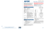
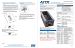
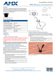
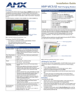
Installation Guide
#4 Plastite screws
(provided)
Notch on Lift Spring Assembly
HPX-1600 Retractable Connection Port
The notch on the Lift Spring Assembly
fits into the slot on the Bottom Cover
Slot on Bottom Cover
Lift Spring Assemblies
AC Power Socket
Power Cord
Bottom
Cover
1) Select a Suitable Location For the HPX-1600
The HPX-1600 HydraPort Retractable Connection Port (FG550-cc) is the first
completely modular, retractable cable connection system built to accommodate the
diverse connection needs of conference and meeting room visitors.
The HPX-1600 is designed to be mounted into a horizontal surface such as a
conference room table or lectern in order to provide connectivity for power,
networking, Audio/Video and control. Specific connectivity is accomplished by
populating the HPX-1600 Base Assembly with various modules.
ATTENTION: Only a professional, AMX-qualified installer should perform this
installation. Installation must conform to all local codes. This product may not
be installed by the end-user.
Note the space requirements for installing the system (FIG. 1).
Product Specifications
Mounting
Sleeve
Clip
Overview
HPX-1600 Specifications
Dimensions (HWD):
FIG. 11 Installing the Power Cord
9) Install Shields
FIG. 10 Inserting the Lift Spring Assembly Into the Bottom Cover
6) Install the System Into the Mounting Surface
Turn the system over and install the unit into the cutout in the mounting surface.
• Make sure that all cables from the backside terminations pass through the
cutout.
• Note that any fixed cables should already be passed through both the mounting
surface and retaining ring.
7) Install the Retaining Ring
1.
2.
3.
•
•
•
4.
•
•
Insert the four #6-32 x 1 3/8 retaining screws into the retaining ring.
Note the orientation of the retaining ring. This orientation changes in order to
accommodate the various thicknesses of mounting surfaces (see FIG. 5 on
page 2).
Note the direction of the screw bosses.
For mounting surfaces less than 35mm thick, orient the screw bosses away form
the main assembly (down).
For mounting surfaces greater than 35mm thick orient the screw bosses toward
the main assembly (up).
Place the retaining ring over the lower portion of the base assembly and against
the underside of the mounting surface.
If an accessory mounting bracket HPX-AC-MB (FG559-21) is to be used, install
it now by trapping it between the retaining ring and mounting surface
Gradually tighten the 4 retaining screws to secure the unit in the mounting surface.
Ensure the unit is properly aligned in the mounting surface.
Torque the retaining screws to approximately 3 in-lbs.
Do not over tighten the screws.
After tightening the retaining screws ensure the unit moves smoothly up and
down.
Over tightening the retaining screws can cause the system to bind.
If the system binds, gradually loosen the retaining screws until it operates
smoothly.
8) Install Power Cord (If Required)
If AC power modules are to be used in International models (FG550-BL, FG550-SL),
install a suitable 14AWG power cord into the provided IEC 320 C14 socket.
Fold the power cord back 180 degrees, and secure it to the far side of the bottom
cover using the supplied wire ties. (FIG. 11).
Note: Insure the resulting service loop is tight enough so that it does not rub the
shields when the unit moves up and down.
1.
Secure the 2 shields to each other using the 8 supplied screws.
2.
Ensure that any fixed cables pass through the assembled shield appropriately.
3.
Snap the assembled shield onto the lower portion of the mounting sleeve.
Install the 4 additional mounting screws into the top of the shield to secure the shield
to the mounting sleeve
10) Secure Cables
Terminate the backside connections as required for each cable exiting bottom of the
HPX-1600. Secure these cables and the power cable to the 4 tabs provided on the
retaining ring using the supplied wire ties (FIG. 12).
Max above
mounting surface:
9.57" x 10.55" x 4.53"
(243mm x 268mm x 115mm)
Max below
mounting surface:
15.08" x 11.54" x 6.26"
(383mm x 293mm x 159mm)
Min. mounting surface
thickness:
19mm (.75in)
Max mounting surface
thickness:
50mm (2.0in)
Weight:
Base Assembly only:
2 Kg (4.41 lbs)
Typical Installation:
3 Kg (6.61 lbs)
Models Available:
• International, Black trim (FG550-BL)
• International, Silver trim (FG550-SL)
Enclosure
Natural finish metal frame with plastic top and bottom covers
moving vertically in a plastic sleeve assembly.
• Matt black top cover and trim ring (FG550-BL, FG550-01BL) or matt silver top cover and trim ring (FG550-SL,
FG550-01-SL).
• Matt black module face plates on all I/O modules.
Rear Connections
Included rear connection – IEC 320 C14 Power cord
receptacle (FG550-BL, FG550-SL), Included AC Power Cord
(FG-550-01-BL, FG550-01-SL).
Rear connections for individual modules are routed through
openings in the unit’s bottom cover.
Tabs/Wire Ties (2 on each side)
Mounting Surface
Retaining Ring
Optional Accessories:
HPX-AC-TK Hydraport Installation Tool Kit (FG559-90)
HPX-AC-HSP Hydraport Spring Kit for Heavy Loads
(FG559-42)
The following table lists the components of the (optional) HPX-AC-TK Hydraport
Installation Tool Kit:
Optional HPX-AC-TK Hydraport Installation Tool Kit (FG559-90)
Quantity Description
Shields
Cables from bottom
of HPX-1600
FIG. 12 Secured Service Loop
•
Ensure there is sufficient service loop to allow the system to travel in its full
range of motion.
• Avoid excess service loop as this can place significant weight on the sliding and
lifting mechanism and prevent the system from functioning properly.
• Ensure the service loop does not catch on the shields or any other obstruction
and is away from users who might kick or snag the cables.
• Secure the cables in at least one additional location after they have been
secured to the retaining ring so as to prevent undue stress on the system if the
cables are inadvertently kicked, snagged or pulled.
Note: The socket-outlet (Connection to Mains Power branch circuit) shall be installed
near the equipment and shall be easily accessible.
Additional Documentation
For more detailed installation instructions with additional drawings, please refer to the
HPX-1600 Installation Guide, available to view or download from www.amx.com.
page 4 of 4
For full warranty information, refer to the AMX Instruction Manual(s) associated with your Product(s).
3/12
©2012 AMX. All rights reserved. AMX and the AMX logo are registered trademarks of AMX.
AMX reserves the right to alter specifications without notice at any time.
3000 RESEARCH DRIVE, RICHARDSON, TX 75082 • 800.222.0193 • fax 469.624.7153 • technical support 800.932.6993 • www.amx.com
93-0550-01
REV: C
(1)
HPX-AC-TMPLT 559-91 router template
(4)
Mounting Strips
Note: The Mounting Strips are manufactured by 3M™. The 3M part number is
“17021P”.
(1)
Router bit (Freud 12-128 or Whiteside 1072)
(1)
Guide Bushing (Woodcraft 144693)
(1)
Lock Nut (Woodcraft 144696)
(1)
Installation Guide
FIG. 1 Hydraport System Space Requirements
•
The Hydraport system requires a mounting surface from 19mm (.75in) to 50mm
(2.0in) thick.
• The Hydraport system requires at least the following amount of space below the
mounting surface to install (see FIG. 1):
383mm (15.08”) height below surface
293mm (11.54”) width
159mm (6.26”) depth
• If the system is to be mounted within a column, pillar or other enclosed space
below the mounting surface, please note that final assembly and termination will
require the installer to have access to this space below the mounting surface.
Care should also be taken to ensure that the system does not interfere with the normal
use of the workspace. For example, on a table or work surface, ensure that the
system does not interfere with the user's legs when they are seated at the table.
Note: Even when the system is deployed in the up position, the mounting system and
shields occupy the entire space requirement below the table.
2) Cut the Hole In the Mounting Surface
Use the HPX-AC-TK router template (FG559-90) and a suitable router with ½” arbor to
create the hole in the mounting surface. FIG. 2 provides the hole cutout dimensions for
reference:
The following sections describe the preparation, installation and setup of the
HPX-1600 Hydraport Base Assembly, using the HPX-AC-TK Hydraport Installation
Tool Kit (FG559-90).
Note: Read these instructions in their entirety before beginning the installation. The
installation requires specific steps to be performed in specific order.
CAUTION: This installation kit requires specific woodworking skills. This
installation should be performed by an experienced person, comfortable with
these type of woodworking operations. Improper use of this tool kit may result
in damage to the mounting surface. AMX is not responsible for damage caused
by improper use of this tool kit.
A typical installation will include several of the available modules. Each of these
modules has specific instructions for terminating their rear connections. Refer to the
installation guide for each appropriate module during the installation of the Hydraport
system.
FIG. 2 Hole Cutout Dimensions
1.
2.
Carefully measure the tabletop or other mounting surface to locate the desired
position of the Hydraport unit.
Apply mounting strips or other appropriate double sided tape to the bottom
surface of the router template, making sure that the rounded edges of the
mounting strips protrude slightly beyond the edges of the template (see FIG. 3).
page 1 of 4
3.
Use the alignment marks scribed on the template to align the template properly
on the mounting surface (FIG. 3).
Mounting Surface
Fixed Cables
Double-sided mounting strips
(4) mounting screws
Bottom Cover
Alignment Marks
Retaining Ring
Double-sided mounting strips
Fixed Cables
FIG. 3 HPX-AC-T Router Template
•
•
•
Note that due to the guide bushing and router bit, the final cutout will be smaller
than the opening in the template. The cutout in the mounting surface will be
offset to the inside of the template opening by 1/8th inch (3.2 mm) on all sides.
Note both the position and orientation of the template relative to the table top or
other mounting surface.
Note that very little clearance exists between the Hydraport assembly and the
hole cutout in the mounting surface. Take care to align the cutout carefully with
the edges or other appropriate features in the table or mounting surface. If the
cutout is misaligned, the installed unit will be misaligned.
Cross-section view of Bottom Cover
showing cable routing
FIG. 8 Bottom Cover - Connect each AC power module to the power inlet assembly
7.
The included circuit breaker modules should also be connected to the Power
Inlet assembly at this time.
Note: International units (FG550-BL, FG550-SL) include 2 circuit breakers for line and
neutral. Both circuit breakers are required for operation. Take care while routing the
wires to the circuit breaker positioned on the opposite side of the chassis from the 2
circuit breaker connectors on the Power Inlet assembly (see FIG. 8).
Refer to the Installation Guides provided with each Module for detailed installation
instructions.
FIG. 4 Fixed Cable Passing Through Ring, Table and Into the HPX-1600 Assembly
Note the direction of the screw bosses, as indicated in FIG. 5:
CAUTION: Ensure the template is held securely on the mounting surface.
4.
•
•
5.
6.
7.
8.
9.
If the template moves during the cutting process, the cutout will be
enlarged and will likely exceed the trim bezel of the Hydraport base
assembly, requiring extensive repair to the mounting surface.
Install the router guide bushing into the base of a suitable router.
The router should be equipped with a ½ inch (12.2mm) collet and a baseplate
capable of accepting a standard 1 3/16 inch (30.2mm) guide bushing.
Install the router bit into the router with an appropriate portion of the bit exposed
below the guide bushing.
Switch the router on and carefully lower (plunge) the router bit into the mounting
surface within the template opening.
Move the router against the template opening such that the guide bushing
follows along the template opening.
Carefully follow the template opening with the guide bushing in a clockwise
fashion such that the cutting action of the router bit is acting against the motion
of the router.
Make several passes with the router, guide bushing and router bit.
Lower the router bit in small increments to remove a suitable amount of material
on each pass.
Mounting Surface
FIG. 6 Installing the Bottom Cover
Retaining Ring
Retaining
Screw
•
•
•
10.
to the mounting surface.
Take care to ensure that the top surface of the mounting surface is not damaged
beyond the width of the trim bezel as the cutout is made.
Make sure the bit or cutting tool used is appropriate for the material to be cut
and will not tear or chip the top surface.
AMX does NOT recommend using a Jigsaw to make the final cutout.
Note that the process of making the cutout will create substantial dust and
prepare the environment appropriately.
Finally, remove template by pulling firmly on the rounded edges of the
double-sided tape mounting strips until they release from the tabletop and
template.
3) Prepare the Terminations
Some modules that are included in the final system require some type of backside
termination. Refer to the installation guide for each module to determine the required
backside termination.
Note: The backside termination for each module can and should be completed before
the module is installed into HPX Base assembly.
Note that for terminations for which the far end of the cable is not accessible either
because the cable has been run under carpet, in a conduit or structure, or is otherwise
fixed, the cable must be placed:
1.
Through the retaining ring, (note the orientation of the retaining ring - see
FIG. 5 on page 2),
2.
Then through the mounting surface from bottom to top,
3.
Then to the module before the module is placed into the base assembly, as
shown in FIG. 4:
4.
Slide the pre-terminate modules one at a time into the Base assembly.
Note the orientation of each module: a small tab exists on the bottom side
(shown facing up in FIG. 7) of the faceplate of each module.
Ensure this tab is facing the bottom side of the system (see FIG. 8).
Retaining
Screw
This tab on each Module faceplate must
face the BOTTOM of the Hydraport system
note the orientation
of the screw bosses
ATTENTION: If modules have been installed in more than 50% of the available
space, the performance of the HPX-1600 retract mechanism may benefit from
the installation of the optional accessory HPX-AC-HSP (FG559-42). See the
installation guide for HPX-AC-HSP for further details.
After the bottom cover is fully secure and the exiting cables are secured:
1.
Clip both lift spring assemblies onto the mounting sleeve.
2.
Ensure the lift spring assembly is oriented properly (FIG. 9).
Lift Spring Assembly
Clip
Retaining Ring
Retaining
Screw
Retaining
Screw
Base Assembly
(bottom of HPX-1600
Mounting Sleeve)
(bottom)
FIG. 5 Direction of the Screw-Bosses, based on surface thickness (19mm vs. >19mm thick)
•
•
For mounting surfaces less than 35mm thick, orient the screw bosses away form
the main assembly (down).
For mounting surfaces greater than 35mm thick orient the screw bosses toward
the main assembly (up).
(detail view of Module Faceplate)
4) Insert the Modules
ATTENTION: See Step 4.5 for the installation of High Voltage Isolators
(HPX-PA-HVI) These Isolators must be installed properly to maintain product
safety certifications.
Note: All Low-Voltage, Secondary-Circuit (LVSC) Modules must be installed above
the AC Power Outlets and Circuit Breaker Modules in the HPX-1600 Base Assembly.
The LVSC Modules will therefor be installed first.
1.
Latch the system in the closed (down) position.
2.
Place the HPX-1600 Base assembly upside down on a suitable surface to
ensure the top cover is not scratched.
3.
Remove the 4 Mounting Screws that secure the Bottom Cover to the
aluminum frame, and remove the bottom cover. (FIG. 6).
HPX-1600 Base Assembly
(shown here upside-down, as it should be
positioned for inserting Modules)
Top Cover
FIG. 7 Inserting Modules Into the HPX-1600 Base Assembly
5.
•
•
•
6.
page 2 of 4
5) Install the Lift Spring Assemblies
Mounting Surface
CAUTION: Trying to cut too deep in any one pass may result in damage
•
Bottom Cover
(inside view)
Route the cables from each module out the bottom (currently facing up) of the
base assembly.
If both low-voltage, secondary circuit (LVSC) modules and AC Power Outlets will
be installed, place the (LVSC) modules in the upper portion of the chassis first,
followed by the AC Power Outlets in the lower portion of the chassis.
The LVSC Modules and the AC Power Outlets must be separated by the High
Voltage Isolators provided in this kit.
See the Instructions provided with the High Voltage Isolators for detailed
installation instructions.
For AC power modules, plug the provided wire harness into the Power Inlet
assembly inside the bottom cover (FIG. 8).
FIG. 9 Lift spring assembly clipped to main sleeve
3.
4.
5.
6.
7.
Unlatch the sliding frame and mounting sleeve so the sleeve is free to slide
relative to the frame.
Slide the mounting sleeve so that it is nearest to the bottom cover.
Take hold of the body of one lift spring assembly and pull it firmly up so that it
can be snapped into the provided slot in the bottom cover (FIG. 10).
Repeat for the second lift spring assembly
Slide the mounting sleeve towards the top of the unit until the unit latches in the
closed position.
page 3 of 4