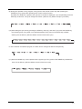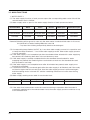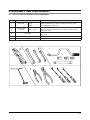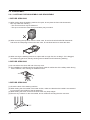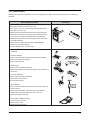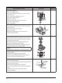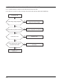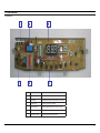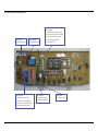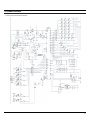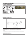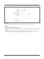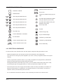
1
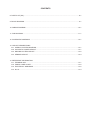
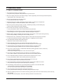
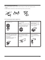
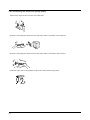
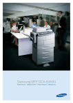
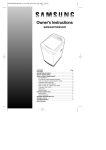
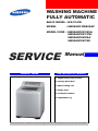
WASHING MACHINE FULLY AUTOMATIC BASIC MODEL : WA17L9W MODEL : SW85ASP/SW82ASP MODEL CODE : SERVICE PRODUCT IMAGE SW85ASPIW1/XSA SW85ASPIW1/YMI SW82ASPIW/XSA SW82ASPIW/YMI Manual THE FEATURE OF PRODUCT 1. Digital Fuzzy Logic Control 2. Opaque Steel Door 3. Water Saving Tub 4. Magic Filter 5. Centerjet Pulsator 6. Adjustable Leg Refer to the service manual in the itself (http://itself.sec.samsung.co.kr/) for the more information. CONTENTS 1. PRECAUTIONS 1-1. SAFETY PRECAUTIONS..................................................................................................................1-1 1-2. PRECAUTIONS UPON INSTALLATION...........................................................................................1-2 2. PRODUCT SPECIFICATIONS 2-1. THE FEATURE OF PRODUCT.........................................................................................................2-1 2-2. SPECIFICATIONS OF PRODUCT....................................................................................................2-2 2-3. THE COMPARATIVE SPECIFICATIONS OF PRODUCT.................................................................2-3 2-4. OPTION SPECIFICATIONS..............................................................................................................2-4 3. OPERATING INSTRUCTIONS AND INSTALLATION 3-1. EACH KEY AND DISPLAY................................................................................................................3-1 3-2. FUNCTION OF CONTROL KEYS.....................................................................................................3-2 3-3. MAIN FUNCTIONS............................................................................................................................3-6 4. ALIGNMENT AND ADJUSTMENTS 4-1. ERROR MODE..................................................................................................................................4-1 4-2. TEST PROGRAM MODE...................................................................................................................4-2 5. ASSEMBLY AND DISASSEMBLY 5-1. TOOLS FOR DISASSEMBLY AND ASSEMBLY...............................................................................5-1 5-2. DISASSEMBLY..................................................................................................................................5-2 5-3. ASSEMBLY........................................................................................................................................5-6 6. TROUBLE DIAGNOSIS 6-1. PRECAUTIONS FOR THE REPAIR AND REPLACEMENT.............................................................6-1 6-2. TROUBLE DIAGNOSIS AND SHOOTING ON MAIN FAILURE........................................................6-2 7. EXPLODED VIEWS AND PARTS LIST 7-1. ASSY-COVER TOP...........................................................................................................................7-1 7-2. ASSY-TUB.........................................................................................................................................7-2 7-3. ASSY-CASE.......................................................................................................................................7-3 CONTENTS 8. PARTS LIST (SA).....................................................................................................................................8-1 9. BLOCK DIAGRAM...................................................................................................................................9-1 10. WIRING DIAGRAM..............................................................................................................................10-1 11. PCB DIAGRAM....................................................................................................................................11-1 12. SCHEMATIC DIAGRAMS ..................................................................................................................12-1 13. CIRCUIT DESCRIPTIONS 13-1. OVERALL SYSTEM DIAGRAM.....................................................................................................13-1 13-2. AC INPUT & POWER CIRCUIT.....................................................................................................13-1 13-3. DRIVING SYSTEM CIRCUIT.........................................................................................................13-2 13-4. SENSOR CIRCUIT........................................................................................................................13-3 14. REFERENCE INFORMATION 14-1. TERMINOLOGY.............................................................................................................................14-1 14-2. FABRIC CARE CHART..................................................................................................................14-2 14-3. ELECTRICAL WARNINGS............................................................................................................14-2 14-4. Q & A..............................................................................................................................................14-3 1. PRECAUTIONS 1-1. SAFETY PRECAUTIONS 1. Do not allow the customer to repair product. The person may be injured or the product life may be shortened. 2. Be sure to unplug the power cord before starting to service (especially when servicing the electrical parts). Take extreme care of the electric shock. 3. Do not plug several plugs in the same outlet. It may cause the fire due to overheat. 4. Check it power plug or outlet is damaged, pressed, dented, or melted by hot temperature. Replace promptly if it is defective. (electric shock or fire hazard) 5. Be sure to ground. (Check grounding of outlet + additional grounding of metal water pipe) Electric shock hazard due to electric leakage 6. Do not clean the main body by directly using water. It may cause electric shock or fire and may shorten the product life. 7. Avoid exposing the wire harness to moisture and secure tightly during servicing. Secure wiring so as not to get loosened or deviated when given an impact. 8. Remove dirts or foreign materials around the housing, wire harness, contact points during servicing. Prevent the possibility of catching fire due to tracking or short. 9. Check if there is any evidence that electrical parts or harness has been exposed to moisture. If it has been exposed to moisture, replace the part or completely remove moisture. 10. Check the parts assembly status after servicing. Maintain the same status as before servicing. 11. When unplugging the power cord, hold the head part of the power cord. There may be dangers of electric shock or fire when the power cord is damaged. 12. Leave the power cord unplugged when the washing machine is not being used. There may be dangers of electric shock or fire due to a strike of lightening. 13. Do not use or store the spray or inflammable materials (including gasoline, thinner, alcohol etc.) nearby the washing machine. There may be dangers of explosion or fire due to electric spark. 14. Do not put a water-containing bowel or wet laundry on the washing machine. If the water is spilled, it may cause electric shock or fire to the washing machine. 15. Do not install the washing machine in a place which is exposed to rain or snow. It may cause electric shock or fire and may shorten the product life. 16. Do not press control buttons by using a pointed tool such as awl or pin. It may cause electric shock and trouble to the product. 17. Check if the washing machine is leveled horizontally and securely installed on the floor. The product life may be injured by the spinning tub. (checking) 18. If the washing machine does not stop the dehydration tub within 15 seconds after there cover is opened, stop using immediately and let it repaired. The user may be injured by the spinning tub. (check shaft) 19. Use connectors for joining the wires and secure them firmly. It may cause fire due to tracking if connected by using the adhesive tapes. 20. When the washing machine is to be laid for servicing, put the pad on the floor first and then lay the ma chine by side carefully. The parts may be damaged by TUB, if the washing machine is to be laid on front. 1-1 1-2. PRECAUTIONS UPON INSTALLATION 1-2-1. Instruction for Installation Environment 1. Install the washing machine on a solid and level floor. 2. Place the machine at least 10cm away from the wall. 3. Placement on an inclined, weak or rough floor may cause abnormal trembling. 1-2-2. Balance See if machine is placed level by checking the position of the washing tub. * Open the lid of the machine, pour water into the tub up to the level just below the pulsator, and adjust the legs so that the pulsator is positioned at the center of the (a) water as shown in the figure. (a) * To control the machine level, turn 10cm away the wall. WATER WATER (b) 1-2-3. Controlling the Front Adjustable Leg To control the height, turn the adjustable leg. (a) (b) 1-2 (b) (a) 1-2-4. Connecting the Drain Hose 1. After pressing the joint ring (a), insert the drain hose (b) in the drain outlet. (same as pump model) 2. Install the drain hose about 80~100cm above the ground. (for pump model) (b) (a) (b) 1-2-5. Connecting the water supply hose 1. Remove the adaptor from the water supply hose. 4. Connect the water supply hose to the adaptor. Pull down part (c) of the water supply hose. When part (c) is released, the hose is automatically connected to the adaptor, and makes a ‘click’ sound. 2. First, using a “+” type screwdriver, and then loosen the three screws on the adaptor. Next, take the adaptor and hold parts (a) and (b) with a gap about 5mm between them. 3. Connect adaptor to the water tap by firmly tightening the screws. Then turn part (b), following the arrow, and put (a) and (b) together. a a b b 5. Connect the other end of the water supply hose to the inlet water valve at the washer. Screw the hose clockwise, all the way in. 6. In case that the water tap is a screw type, connect a water supply hose that fits to the tap as shown. c 1-3 1-2-6. Positioning the Drain Hose (pump model) Take out the cap-hose and connect the outlet-hose. Be sure to join tightly the drain hose into the drain-outlet on the back of the machine. Be sure to join tightly the drain hose into the drain-outlet on the side of the machine. Install the drain hose in the position of about 90~100cm above the ground. 1-4 2. PRODUCT SPECIFICATIONS 2-1. THE FEATURE OF PRODUCT WATER SUPPLY HOSE RED-HOT WATER DRAIN HOSE LID WATER SUPPLY HOSE WHITE-COLD WATER DETERGENT BOX MAGIC FILTER POWER PLUG BLEACH INLET FABRIC SOFTENER DISPENSER HEIGHT ADJUSTING LEG 2-1 2-2. SPECIFICATIONS OF PRODUCT Classifications Specifications Model SW85ASP/SW82ASP Washing Capacity 8.5kg Washing Method Stirring Type Rated Voltage 230~30V/50Hz Wash 550W Spin 310W Maximum 92 ℓ High 78 ℓ Medium 62 ℓ Med-Low 48 ℓ Extra Low 32 ℓ Power Consumption Standard Water Level Maximum Water Usage Applicable Water Pressure Spin Speed Weight Dimension 2-2 240 ℓ 0.05~0.78 Mpa (0.5~8.0kgf/㎠ ) 710 rpm 47kg W630×D675×H1060 2-3. THE COMPARATIVE SPECIFICATIONS OF PRODUCT SW85ASPIW1/XSA SW85ASPIW1/YMI SW82ASPIW/XSA SW82ASPIW/YMI 8.5kg 8.5kg Rated Voltage 230~40V/50Hz 230~40V/50Hz Water Supply Hot+Cold+Rinse Hot+Cold+Rinse Basket Type All Stainless All Stainless Mirror + Button Inlay Door Steel Steel Color Neat White Neat White Model Specifications Washing Capacity Control Panel Type Weight Dimension 47kg W630×D675×H1060 2-3 2-4. OPTION SPECIFICATIONS Item 2-4 Item Name CODE.NO QTY ASSY-HOSE WATER DC91-10229E DC91-10229F 2 ASSY-HOSE DRAIN(O) DC97-00139C 1 MANUALBOOK DC68-02340* 1 REMARK 3. OPERATING INSTRUCTIONS AND INSTALLATION 3-1. EACH KEY AND DISPLAY Note : The real control panel has the same layout and function as the above figure’s expression. 3-2. FUNCTION OF CONTROL KEYS 1. PROGRAM KEY (1) Before the initial start key is entered or during the pause mode, each pressing of this key shows the selectable Programs as in the order below. SENSOR �������� → �� BEDDING �������� → ��� HEAVY ������ DUTY ����� → ��� ECONO ������ WASH �������� → QUICK ������ → �� WOOL ���� (2) Each time you press the key during the valid operation, it gives a beep sound for each key-in but it does not perform any corresponding action. (3) When you press PAUSE key and then change the current program into the new program, the current ....................................................................................................... program����������������������������������������������������������������������������������������������� will be reset as the initial default values of the newly selected ���������������������������� program��������������������� even though you have set up the current program�������������������������������������������������������������������������� ��������������������������������������������������������������������������������� which has it’s own manual function by using the manual key (wash, rinse, spin). (4) In case the selected ������������������������� program������������������ is available and being ������������������������������������� operated, you can press all of the �������������������� keys except for the RESERVE key (DELAY START key) and �������� PROGRAM������ ����� key. (5) Weight sensing function is valid only for Sensor, BEDDING(HEAVY), ECONO WASH(ECONO), ........ QUICK��, SUPER CLEAN ��������� programs�. When you press WATER LEVEL key, water level is selected in the order below. The initial key-in for WOOL ������������������������ program��������������������������������������������������������������� has the default ��������� value of ������������������������������������� the water level as Medium level even though you don’t press WATER LELEL key. 3-1 (6) Function Table for Programs WASH TIME DIVISION SENSOR BEDDING/ HEAVY HEAVY DUTY ECONO WASH QUICK WOOL MANUAL SET 6~30 min 6~30 min 6~30 min 6~30 min 1~15 min 1~15 min MAXIMUM 20 min 15 min 20 min 18 min 5 min 5 min HIGH 20 min 15 min 20 min 18 min 5 min 5 min MEDIUM 20 min 15 min 20 min 18 min 5 min 5 min MED-LOW 15 min 15 min 20 min 18 min 3 min 5 min EXTRA LOW 15 min 15 min 20 min 18 min 3 min 5 min MANUAL SET 1~5 ����� times 1~5 ����� times 1~5 ����� times 1~5 times 1~5 ����� times 1~5 ����� times INITIAL VALUE 2 times ����� 2 times ����� 2 times ����� 1 time ���� 1 time ���� 2 times MANUAL SET 1~9 min 1~9 min 1~9 min 1~9 min 1~9 min 1~9 min INITIAL VALUE 5 min 5 min 5 min 3 min Max,High,Med : 3 min, Med-low Low : 1 min 1 min INITIAL WATER SUPPLY Cold Water Cold Water Cold Water Cold Water Cold Water Cold Water WEIGHT SENSING WATER LEVEL Low~ Maximum Low~ Maximum Low~ Maximum Low~ Maximum Low~ Maximum Medium RINSE SPIN TIME (7) When the PROGRAM key is available and being operated, you can update the corresponding function by pressing the manual key. But the cycle-off should be skipped. (8) At the Sensor program which is the initial program mode after power-on, every press of the manual keys only performs the manual function. Sensor program is automatically selected when POWER key is pressed. You may change the Sensor program into the other programs before pressing the START key and also you can select the corresponding manual function by pressing the manual keys. In case before pressing the START key, the manual function of each program can be performed by pressing the PROGRAM key first and then manual key. Otherwise, the press of the manual key after pressing the START key enables you to set up the corresponding function. In case during the operation of any program, you can perform the manual-only function of each program by pressing the PAUSE key, changing the program, and selecting the manual only function and then finally pressing the START key. 3-2 (9) During the operation of any program, every press of the manual control key after pressing the PAUSE key may change the operating time of each manual function. Ex) When the SPIN key is pressed, the spin time of “5 MIN” is displayed. If you sequentially press the SPIN key at this time, it may be changed as follows. (effective only before the spin cycle starts) (10) After setting the spin time by pressing the SPIN key at the (9), and then if you press the WASH key, the remaining time of any wash cycle would be added. Every press of the WASH key modifies washing time as follows. (effective before the end of the wash cycle) In case of WOOL and QUICK program, the wash time is changed as follows exceptionally. (11) When the RINSE key is more pressed at the (8) and (9), Every press of the RINSE key modifies the rinse time as follows. (effective before the end of the rinse cycle) 3-3 2. WATER SUPPLY KEY (1) This key is valid except for error cases. (2) This key-in changes the mode as follows. Cold Water �� →� ��������������� Hot/Cold Water �� →� ��������� Hot Water (3) If you select any water supply by pressing the WATER SUPPLY key, the selected water supply remains valid even if you change the program mode(except for WOOL program). If you move to the WOOL program, the cold water is automatically selected, but the previous setting is restored if you switch to the other program. (4) Error cases as follows in above item (1). - Water supply error - Drain error - Water sensing error (5) While water is being supplied, the corresponding water supply lamp ftwinkles by 1 sec. 3. START/PAUSE KEY (1) This key-in toggles between start and pause as follows. Start �� →������ ����� Pause (2) This key performs error clear function. - Water supply error - Drain error - Water sensing error 3-4 4. WATER LEVEL KEY (1) The WATER LEVEL key is always valid except for error cases as below. * Error: - Water Supply Error - Drain Error - Water sensing error (2) Pressing the Water Level key shows the options in the order as below. Middle → ● → High → ● → Maximum → ● → High → ● → Middle → ● → Low → ●Extra low → Lowest ● Low ← ● ← Extra low (3) When the WATER LEVEL key happen to be touched before the MOTOR starts to rotate after the water-feeding, the time of water feeding is automatically adjusted to the water level and so the time is recalculated. (4) The washing time with any selected water level at each program can be modified only before the motor starts to rotate. Otherwise, after the motor started to rotate, the wash cycle will be performed with the washing time which was already set at the old water level regardless of the water level. (5) In case of adjusting the washing time by the WASH key at the (4), the washing time is to be recalculated with the new time setup, regardless of the water level. (6) When the water level is not selected, the segment display is “-:--”. When the WATER LEVEL key is pressed, the total cycle time is displayed in the segment. Default value for the water level is selected medium. 5. RESERVE KEY (DELAY START KEY) (1) Reserve key-in is available only before entering start-key under the condition of pressing any program. (2) Default value of this key is 3 hours. (3) Each key-in can update the reserved time by 1 hour to the maximum 19 hours. (4) It’s possible to change the reserved time within 10 min after pressing the START key. It’s not valid to change the time after 10 min. (5) Manual wash time, rinse time and spin time can be adjusted only after pressing the start key in 10 min. If total working time is over 3 hours automatic reserve process is canceled and return to the early condition. 3-5 3-3. MAIN FUNCTIONS 1. WATER SUPPLY (1) The water supply function of each process opens the corresponding water valve ON until the selected water level is fulfilled. (2) Water supply valve is open for the water supply function of each process as below. Selected Wate Wash Rinse Rinse2 Water plus Intermittent spin Cold Water Cold Water Cold Water Cold Water Cold Water Cold Water Hot/Cold Water Hot/Cold Water Hot/Cold Water Cold Water Cold Water Cold Water Hot Water Hot Water Hot/Cold Cold Water Cold Water Cold Water Remarks) Washing will progress in case only the warm water is selected.Cold water in 20 sec at the initial time of water feeding Make the valve ON → To protect the clothing and perfectly dissolve the detergent. (3) Corresponding lamp flashes ON/OFF by 1 sec when water supply process is in operation and or keep the lamp ON when it’s not in the water supply process. when water supply process is not in operation. (4) If the water supply is not completed yet after the standard time allocated for water supplying has passed, the remaining time does not count down any more. (5) If the water supply is already completed before the standard time allocated for water supplying has passed, the remaining time counts down as much as the standard time and then proceed to next step. (6) If the water supply is not completed even after 60 minutes has passed, water supply error function is performed. (7) If a WATER LEVEL key is entered again after the water supply is all finished, and if the newly set level is higher than the current level, then the water supply process is performed again, and the washing motor is turned OFF and the remaining time does not count down during water supply. (8) Water supply washing motor table for each water level. Water level Maximum High Medium Med-Low Low, Extra Low Supply level 5 min 4 min 30 sec 4 min 2 min 30 sec 2 min (9) If the water level comes down under the reset level during in operation after the water is completely supplied up to the selected water level, the water supply process continues on up to the selected level. 3-6 2. INTERMITTENT SPINNING (1) Opening the door while the intermittent spin is in operation stops spinning and generates door open alarm (door open melody 5 times). (��������������������������������������������������������������������������������������������������� 2) If the door is closed while the door open alarm is ongoing, the alarm status is terminated and proceeds to the next step in as identical order as in START/PAUSE key-in. (������������������������������������������������������������������������������������������� 3) If the safety S/W senses the unbalance state during the intermittent spinning cycle, it performs the unbalance clear function. ■ Unbalance Sensing Function - S/W Sensing Time UNBALANCE: 20~500mS Door ��������������������������� Open: 501mS or more. . - When the door is opened, the OFF time of the motor is at the time that the 20mS is detected. ������������������������������������������������������������������������������������������ If the door is closed while the door open alarm is undergoing, the alarm status stops ����������������������������������������������������������������������������������� and the drain motor turns ON. and then after 10 sec, the washing motor works. ����������������������������� ■���������������������������� Unbalance Clear Function - If the unbalance is detected at the spin cycle of any program (except for spin only mode), the ������������������������������������������������������������������������������������������ spin cycle stops, the release wash/rinse function is performed and then the spin cycle works ������������ again. The ����������������������������������������������������������������������������������������������� unbalance clear function like this, which is valid until 2 times. But If it is 3 times, it displays ��������������������������������������� “UE” error, all of cycle stop. 3. SPIN FUNCTION (1) The spin function allows the washing motor to rotate to the left and to maintain the drain motor ON for the whole spinning time. (2) Other functions are as identical as Intermittent spin function. (3) The spinning time after each wash cycle, rinse cycle, and the final spin cycle follow the time chart. 4. PAUSE FUNCTION (1) The pause function turns off the motor for 1 min and turns on only the drain motor on for 30 secs. (2) If the door is opened while the pause function is in operation during the rinse cycle, it gives door open error and resumes the process after door is closed. (3) If the door is opened while the pause function is in operation during the spin cycle, it ends the spin function. 3-7 5. WATER SUPPLY FUNCTION (1) Identical as the water supply function of wash process. 6. RINSE FUNCTION (1) If a selected water level is fulfilled, the rinse function is performed. (2) Rinse time is 2 min 30 sec at 1 time for most of programs except for the following programs. (2 min for WOOL program, 1 min 30 sec for ECONO WASH program) 7. SPIN FUNCTION (1) It is identical as the intermittent spin and spin function of the rinse process. (2) Spin fuction performs for only 1 min at WOOL program. 8. EXIT FUNCTION (1) After all the selected process is completed, it performs exit process. (2) While the exit function is in operation it gives end melody and turns off all the driving com partment. The display shows “END”. (3) If the exit function is finished, it automatically turns power relay off. 3-8 4. ALIGNMENT AND ADJUSTMENTS 4-1. ERROR MODE 4-1-1. ERROR FUNCTION 1. WATER LEVEL SENSOR ERROR (1) When the water level senser detects a frequency less than 15kHz or more than 30kHz for more than 5 seconds (2) Generates ERROR MELODY 5 times. (3) DISPLAY: ‘1E’ 0.5 sec ON/OFF (4) How to Clear: Press the START key to check again. 2. WATER SUPPLY ERROR (1) When the water supply does not reach at the selected water level after 60 min has passed since starting to supply water. (2) Generates ERROR MELODY 5 times. (3) DISPLAY: ‘4E’ 0.5 sec ON/OFF (4) How to Clear: Press the START key to clear the error status and to resume the water supply function. 3. DRAIN ERROR (1) When the water level does not fall under reset level after 15 min has passed since starting to drain. (2) Generates ERROR MELODY 5 times. (3) DISPLAY : ‘5E’ 0.5 sec ON/OFF (4) How to Clear : Press the START key to clear the error status and to resume the water drain function. 4. DOOR OPEN ERROR (1) When the door is opened during the intermittent spin and spin. (2) Generates ERROR MELODY 5 times. (3) DISPLAY: ‘dE’ 0.5 sec ON/OFF (4) How to Clear : Close the door. 5. UNBALANCE ERROR (1) In case the unbalance is sensed three times during the same spin cycle. (2) In case the ERROR MELODY sounds five times. (3) DISPLAY: ‘UE’ 0.5 sec ON/OFF (4) How to Release: Open the DOOR and then close it. 4-1 4-2. TEST PROGRAM MODE 4-2-1. TEST MODE FUNCTION (Drive and other test) 1) How to enter. (Water level+Course+Power s/w) 2) All of the PCB display when you press three buttons. 3) If you depress the three buttons, it shows the micom model number in 2 seconds and then shows the software version. 4) Mode change: you may change mode by pressing Start/Hold button in test mode. 5) Press the Start/Hold button one time. (Segment display: ‘ㅂ’) The wash course started only Maximum water level. (Digital course) 6) Press the Start/Hold button two times. (Segment display: ‘ㅂH’) The wash course started only Minimum water level. (Digital course) 7) Press the Start/Hold button three times. (Segment display: ‘L’) The water supply entered until Maximum water level. 8) Press the Start/Hold button four times. (Segment display: ‘S’) The Spin Course started by Semi-spin Course finished. PCB senses the motor error when they didn’t exists 30 taco-pulses in Semi-spin runs on 4times, 30 seconds. (Door error, Unbalance error) 9) Press the Start/Hold button five times. (Segment display: ‘HA’) The weights sensing runs, and display the weighting pulse on segment. 10)The washing machine power is off when press the Start/Hold button six times. 11)The washing machine runs the extra function when you press the Start/Hold button between one pressing and five pressing. 12)When the water supply button is entered, shows the selectable courses as in the order below. Cold → Rinse → Hot → Off If you press the Water supply button when water supplies, it didn’t effect. 13)When the water level button is entered, shows the selectable courses as in the order below. If you press the Water level button when motor runs, it didn’t effect. 14)When the Wash button is entered, shows the selectable courses as in the order below. Drain → OFF 4-2 If you press the Wash button when drain-motor runs, it didn’t effect. 4-3 Memo 4-4 5. ASSEMBLY AND DISASSEMBLY 5-1. TOOLS FOR DISASSEMBLY AND ASSEMBLY NO. TOOL 1 Box driver 2 Double-ended spanner 10 mm 13 mm 19 mm Heater (1) Motor (1), Balance (5), 2 holes of each left and right of the shock absorber 1 Pulley hole 10, 13, 19 mm Replaceable for the box driver. Since the bolt runs idle when the box driver is used, use the box driver 17mm. Tool to protect the idle and abrasion of the bolt for the box driver. 3 Vice pliers 4 Other (Driver, Nipper, Long nose) General tools for the after service. 5 JIG for the BASKET SPIN ASSY 1 (Disassemble and Assemble) 5-1 5-2. DISASSEMBLY 5-2-1. CAUTIONS FOR DISASSEMBLY AND REASSEMBLY 1. BEFORE SERVICING (1) When laying down the washing machine for repair, do not place the front side downwards. This may cause the following : - The round front face may be deformed. - The top-cover and the outer-case (round area) may not match. (2) When removing the top-cover from the outer-case, do not let the wire bundle fall downwards and touch the sharp edge of the outer-case. Also, do not allow tension to stress the wires. (3) When moving the washing machine to a place with a rough floor, do not drag it. If it is dragged, the rubber may get loose, thereby causing severe vibration and noise during washing. 2. BEFORE SERVICING (1) Do not deform the check-S/W rod of the top-cover. (2) The installation of a deformed check-S/W rod will result in malfunction of the safety switch during severe vibration, thus causing an unbalanced error. 3. BEFORE SERVICING (1) Check the level of the washing machine. (2) When setting the wire bundle in the lower section, make sure that the wire bundle is not stressed by any tension due to tilting of the tub assembly. (3) When setting the wires, do not let the wires touch any sharp edges. (4) Remove any moisture on the wire bundle, and on areas surrounding the wire connector. 5-2 5-2-2. DISASSEMBLY Warning! To avoid risk of electrical shock, personal injury or death, disconnect the power to the washing machine. Disassembly Procedure ■ Removing the PCB Assembly 1)Remove the Screw to fix the Cover-T.C. 2)Lift up the Cover-T.C with the Control-Panel assembled. 3)Turn the Cover-T.C “up”. 4)Disconnect the Wire Harness from each electrical parts. 5)Remove the 4 Screws connecting the Control Panel with the Cover-T.C. and then dissemble the Control Panel. 6)Remove the 5 Screws connecting the Control Panel with the PCB Assembly. 7)Disconnect the Wire Harness of the PCB Assembly. 8)Pull away the PCB Assembly. 9)Do the reassembly in reverse order. Illustration ■ Removing the Pressure-Senser, Water-Valve, and Checker Assembly ■ Pressure Senserl 1) Pull out the Lead Wire Terminal of the Pressure Digital. 2) Remove the Pressure Digital. 3) Pull out the Air Hose. ■ Water Valve 1) Pull out the Lead Wire Terminals. 2) Remove the Water valve while pushing it in the direction of the arrow. ■ Checker Assembly 1) Pull out the Lead Wire Terminals. 2) Remove the two Screws. 3) Lift out the Checker. ■ Wire Harness 1) Pull out the Lead Wire Terminals from the parts in back of the Top Cover. 2) Pull out the Lead Wire Terminals from the PCB after dissemble the Control-Panel from the Cover-T.C. 3) Remove the Wire Harness. ■ Door Switch <Magnet Switch> 1) Turn over the top-cover. 2) Remove the screw. 3) Remove the door switch. 5-3 Disassembly Procedure ■ Removing the Motor 1)Remove the Back Cover. 2)Lay down the Washing Machine with the rear side facing the floor. 3)Pull out the Sound Absorption Panel. 4)Remove the Wire Housing. 5)Remove the V Belt. 6)Remove the two Bolts fastening the Motor. 7)Remove the Motor Pulley. 8)Pull out the Motor. ■ Removing the Drain Motor 1)Lay down the Washing Machine with the rear side facing the floor. 2)Pull out the Lead Wire Terminal. 3)Remove the Bolt. 4)Remove the Drain Motor Wire from the Link. 5)Lift out the Drain Motor. ■ Removing the Shaft Assembly 1)Remove the two Screws fixing the Top Cover, and lift up the Top Cover gently tilt the Top Cover back to expose the Tub Cover. 2)Remove the four Screws fixing the Tub Cover. 3)Remove the Bolt fixing the Pulsator. 4)Remove the Spin Nut fixing the flange Shaft and the Shaft and pull out the Spin Basket. Caution Disassemble the Spin Nut in a clockwise direction. 5)Lay down the Washing Machine with the rear side facing the floor. 6)Remove the two Bolts fixing the Saddle. 7)Remove the four Bolts fixing the Shaft using the Box and take out the Shaft Assembly. ■ Removing the Pump Assy 1)Remove the Back Cover. 2)Remove the Lead Wire Terminal and the Earth Wire. 3)Remove the Two Hoses. 4)Remove the 2screws which fix the filter. 5)Lay down the Washer with the right side facing the Floor. 6)Remove the 2 Screws which fix the pump. 7)Lift out the Pump. 5-4 Illustration Remarks 5-3. Spin - Nut Repairing Box 5-3-1. Procedure 1. Insert the jig ® into the spin-nut - . 2. Insert the guide pin ¯ into the groove of the flange - shaft by rotating it to the right and left. 3.Insert the connecting rod ° and handle ± into the sq uare box. Then turn the handle clockwise on the axis of the small box to disassemble (Right-hand thread).* To disassemble the box, give three to four times of instantaneous shocks to the handle in the loosening direction, then disassemble it by turning the handle when the nut is loosened. 4.To disassemble the box, strike the handle three or four times-quick shocks to loosen it-then complete the disassembly by turning the handle as the nut is loosened. 5. Reassemble in reverse order. 5-5 5-4. REASSEMBLY Reassembly procedures are in the reverse order of dissasembly procedures. 5-6 6. TROUBLE DIAGNOSIS - As the washing machine which has the micom processor, is configured of the complicated structure, there might be many kind of the service call from the consumer even though there is no defect on the parts in the machine. Below information is prepared for the exact trouble diagnosis and the suitable repaire guide. 6-1. Precautions for the Repair and Replacement Please observe and follow the below instruction for the trouble diagnosis and parts replacement. (1)As the electric components are easily damaged by the static electricity charged in the resin part of the machine or in the human body, be sure to remove the potential difference between the human body the washing machine by touching the earth strap or the power supply which is connected to the machine if you need to contact PCB parts for servicing. Earth Strap Power Plug (2)The wiring should be properly connected in accordance with the wiring diagram. Erroneous wiring may cause the faulty operation, smoke, or fire. Speial attention should be paid to connection, insulation treat ment, and wiring work for the lead wire. (3)Be sure to pull out the power plug during repair. (4)Be sure to use only authoirzed replacement parts. (5)Be careful that touching the radiating plate accidentally may cause electric shock, because AC 110V 220V is applied between T1 and T2 of the triac on the PCB assembly. (6)As the parts on PCB are coated with urethane, they can not be inspected by the test bar on the multimeter. Check them normal or not by using the test mode first and then diagnose the trouble in an appropriated procedure as next troubleshooting method. 6-1 6-2. TROUBLE DIAGNOSIS AND SHOOTING ON MAIN FAILURE 6-2-1. POWER SUPPLY, DISPLAY, AND KEY SELECTION FAILURE (1) In case of no power on when you plug in the power cord and then press the POWER key No Power ON Yes Is the rating voltage supplied ? No Apply the rating voltage. Yes Is the power plug well connected? No Plug in the power cord securely. Yes Fuse blown out? Yes Replace fuse. No Is the wiring on the power line well connected? Yes The PCB Assy is defective. Replace it. 6-2 No Repair or Replace the wire connection. (2) In case the unselected indicator turns on. Unselected indicator turns on. Replace defective PCB ASS`Y. (3) In case there is no beep sound and also the indicator does not turn on at any key selection. No beep sound and or no display in the indicator Power S/W ON? No Turn Power S/W ON. (All of key selections are valid only when POWER S/W is on.) No Tact S/W or Tact S/W connection with PBA is defective. Replace PCB ASS`Y. Yes S/W contacts in good condition? Yes Replace defective PCB ASS`Y. 6-3 6-2-2. DRIVING UNIT FAILURE - At the below instruction, it is the case that there is no failure on the power supply and key selection. it is the diagnosis of any problem after POWER key and START key are selected and then any operation is being normally performed. (1) In case of no water supply No W/S(water supply) START/PAUSE key is pressed after selecting a course? No Press Start/Pause key. Yes Is there any sound like ‘zee-’ at the W/S valve during water supply? Connect the terminal firmly. No Yes Water tap is opened? No Water supply has been cut off? Yes Yes Turn off the water tap and turn Power OFF. Yes Clean the filter by using a brush. No W/S valve is electrically continuous? Yes Foreign materials exist on W/S hose or valve? Yes No W/S valve is defective. Replace it. Is the water level senser well connected? Yes Do the pulsator rotate? No PCB Assy is defective. Replace it. 6-4 Open the water tap. Yes The terminal of W/S valve is well connected? No No Yes Water level senser is defective. Replace it. (2) In case the water supply does not stop and also the wash does not start. The water supply does not stop Yes Pull out the plug. Yes Does the water supply stop? Yes The water valve is defective. * Remove the foreign material in the water velve. Yes Air is leaking. Check the connection, and apply the adhesives. Yes Is there water in the water level sensor hose? For pump model No No Is the water level sensor hose bent? Yes No Is the water coming out through the drain hose with the operation of the drain valve? Correct the bent hose. For no pump model Yes Check the drain valve. Remove foreign materials such as drawn thread, hair pin and buttons. No Replace the PCB assembly. 6-5 (3) In case the wash starts without the water supply. Wash starts without the water supply Water Level Sensor terminal is securely connected? No Connect terminals securely. Yes Washing is going on? Yes Replace defective PCB ASS`Y. 6-6 No Turn Power OFF and starts to operate again. (4) In case the pusator does not rotate during washing. - This malfunction may be caused by defective contacts of the wire harness. The pulsator dose not rotate. Yes Does the water supply stop after filling to the specified level? No Is the connection of the water lwvwl sensor terminal all right? Yes Replace the water level sensor. Yes Yes Connect the terminal securely. No No Does the motor make a “woong” sound? Replace the condenser. Is water supplied? No No Dose the pulsator operate normally? No No Now it is normal Replace the PCB assembly. Check the motor for shortcircuit and replace it if necessary. Dose the pulsator operate normally? Yes The motor is defective. No Is the V belt positioned correctly? Yes Replace the PCB assembly. No Install the V belt correctly. Check for a racing motor due to excessively strong or weak tension of the V - belt. 6-7 (5) In case the noise occurs during washing. Noise coccurs during washing. Yes Does the noise occur from the inside of the washing tub? No Yes Any foreign materials stuck between the washing tub and the pulsator? Remove any foreign materials. Adjust the clearance of the pulsator. Is there noise from the clutch? No Yes Is there noise from the motor? Contact noise due to the wear of motor bearing. Replace the defective motor assy due to the abrasion state. No Noise of loosing screws from the connection area. Yes Is the position of the brake lever adjusted properly? Yes The noise is either the contact noise inside the clutch, or it is noise caused by the wear and deformation of parts. Replace the defective clutch assy due to the abrasion state. 1. Check the fastening screws for the motor and the motor pulley. 2. Check the caulking of the motor pulley. 3. Check the internal components for any abnormality. * The ‘Sha-ah’ sounds may be heard when the Spin tub comes to a halt but that is not problem of the washing machine as they are coming from normal water flowing inside the spin tub by auto balancing function. 6-8 (6) In case of no spinning No Spinning Is it draining? Yes This is normal as designed to drain before spinning. No Pulsator blades are rotating? No Adjust tension of the Yes V-belt. V-belt tension is too strong or too weak? No Educate customer to Yes close the lid. Is the lid open? No Check and adjust safety switch. Yes Safety S/W terminal is lifted up when lid closed? Yes Drain motor makes operating sounds? Yes Improper adjustment of Clutch part. Repair it. Yes Drain motor shows continuity? No Replace Drain Motor. Yes Drain Motor operable as a single unit? No Replace defective drain motor lead wires. Yes Improper adjustment of Clutch part. Repair it. No Replace safety S/W. Yes Terminals of safety S/W COM and DOOR continuous? No Unbalance 1st, 2nd times automatically dose water Supply → Wash. Remove foreign materials. Spin tub is rotating correctly? Yes No Yes No Any foreign materials between the spin tub and TUB? No Yes Check motor lead wire. OK. Replace defective PCB ASS`Y. Unbalance status? No Yes Spin tub is rotating correctly? No Motor is defective Replace it. 6-9 (7) In case of no draining No Draining No pump model only Drain hose is put down? Yes Put down the drain hose. Yes Drain hose is bent? Yes Position the hose properly. No Press Start/Pause key 3 or 4 times in Drain ·Spin mode. Drain Motor makes operating sounds? Yes No pump model only Connect them securely. Yes Spring joining Drain valve and Motor deviated? No Yes Drain hole of Drain hose is blocked? Remove foreign materials. Yes No pump model only No No Any blocking materials in Drain hole? No OK 6-10 Drain motor is continuous? No Replace defective Drain Motor. No Replace the defective drain motor. Yes Drain pump can operate alone? Yes Wires are securely connected? Yes Any blocking materials in Drain Valve? Take out wash tub (spin tub). Yes No Replace defective PCB ASS`Y. No Connect them securely. 7. EXPLODED VIEW AND PARTS LIST 7-1. ASSY-COVER TOP [ SW82ASP ] PXXXX P0079 C0082 C0115 A0242 P0051 P0007 [ SW85ASP ] P0038 C0002 P0198 P0030 C0082 A0242 D0089 P0075 D0089 P0053 P0031 P0062 P0115 P0018 W0004 7-1 Location. No CODE-NO A0242 DC64-01207A INLAY-PANEL A0242 DC64-01275A A0242 DESCRIPTION SPECIFICATION Q’TY SA/SNA WA17L9,PC,T1.5,W186.5,L57.3, 1 SA INLAY-PANEL WA15L5W,PET,T0.188,W395.6,L9 1 SA DC64-01275B INLAY-PANEL WA15L4W,PET,T0.188,W395.6,L9 1 SA A0242 DC64-01275C INLAY-PANEL WA17L7W,PET,T0.188,W395.6,L9 1 SA A0242 DC64-01275H INLAY-PANEL NEW-SKIPPY/WA14L1/4,PET,-,-, 1 SA A0242 DC64-01275J INLAY-PANEL NEW-SKIPPY/WA14L2/5,PET,-,-, 1 SA A0242 DC64-01275K INLAY-PANEL SKIPPY2,PET,T0.188,W395.6,L9 1 SA A0242 DC64-01275L INLAY-PANEL SKIPPY2,PET,T0.188,W395.6,L9 1 SA A0242 DC64-01275M INLAY-PANEL SKIPPY2,PET,T0.188,W395.6,L9 1 SA C0002 DC97-11213A ASSY-PANEL CONTROL WA17L9,-,BUTTON-TYPE, 1 SA C0002 DC97-11213D ASSY-PANEL CONTROL B27L9WDP/YE,-,-,NEW- 1 SA C0002 DC97-11213E ASSY-PANEL CONTROL NEW SKIPPY,WA15L*,PAN 1 SA C0002 DC97-11213F ASSY-PANEL CONTROL NEW SKIPPY,WA14L1/L4, 1 SA C0002 DC97-11213G ASSY-PANEL CONTROL NEW SKIPPY,WA14L2/L5, 1 SA C0082 DC64-01174A PANEL-CONTROL WA14L1,ABS,-,-,-,-,NEAT-WH 1 SNA C0082 DC64-01174D PANEL-CONTROL WB27L9,ABS,-,-,-,-,SPRAY-S 1 SNA C0082 DC64-01208A PANEL-CONTROL WA14L1,ABS,-,-,-,-,NEAT-WH 1 SNA C0082 DC64-01208C PANEL-CONTROL WA14 L1/2/4/5 WDP/XAX,ABS, 1 SNA C0082 DC64-01208D PANEL-CONTROL WA14 L1/2/4/5 WDP/XAX,ABS, 1 SNA C0115 ASSY PCB PARTS MFS-S1TT25B-09 1 SNA D0089 MFSS1TT25B-09 DC61-00523A HINGE-DOOR PIN SW95ASP,NYLON66(GRASS30%) 2 SA P0007 DC97-01766F ASSY BODY DETERGENT WA15L1W,NEW SKIPPY ( 1 SA P0198 DC90-10104D CHECKER S/W SEW-110J,DC15V/50MA,-,- 1 SA P0030 DC32-30006S SENSOR PRESSURE DN-S17,10KG/STANDARD 1 SA P0031 DC61-20223A HINGE-DOOR(R) ABS,SW90K1SP 1 SA P0038 DC63-00041R CASE-DETERGENT WA14H6Q3DW/XAX,ABS, 1 SA P0051 DC63-00698A COVER-T.C WA14L1,ABS,-,-,-,-,-,NEAT-WHT, 1 SA P0051 DC63-00698B COVER-T.C WA15L5,ABS,-,-,-,-,SEM,NEAT-WH 1 SA P0051 DC63-00698C COVER-T.C WA17L7W,ABS,-,-,-,-,SEM/MEXICO 1 SA P0051 DC63-00698D COVER-T.C WA15L1W,ABS,-,-,-,-,SEM/MEXICO 1 SA P0051 DC63-00698G COVER-T.C WA15L1W,ABS,-,-,-,-,SELA-P(PAN 1 SA P0051 DC63-00698J COVER-T.C WA15L4W,ABS,-,-,-,-,SELA-P(PAN 1 SA P0051 DC63-00698K COVER-T.C WA17L9W,ABS,-,-,-,-,SELA-P(PAN 1 SA P0051 DC63-00698L COVER-T.C WB27L1W,ABS,-,-,-,-,SAMCOL/Col 1 SA P0051 DC63-00698M COVER-T.C WB27L9W,ABS,-,-,-,-,SAMCOL/Col 1 SA P0051 DC63-00698S COVER-T.C WA14L1WDP/XAX,ABS,-,-,-,-,SEM 1 SA P0051 DC63-00698T COVER-T.C WA14L2WDP/XAX,ABS,-,-,-,-,SEM, 1 SA P0051 DC63-00698U COVER-T.C WA14L4WDP/XAX,ABS,-,-,-,-,SEM, 1 SA P0051 DC63-00698V COVER-T.C WA14L5WDP/XAX,ABS,-,-,-,-,SEM, 1 SA P0051 DC63-00698W COVER-T.C WA15L4WDP/YCX,-,-,-,-,-,SELA-P 1 SA P0051 DC63-00698X COVER-T.C WA15L1,ABS,-,-,-,-,SELA-P,NEAT 1 SA P0051 DC63-00973D COVER-T.C SKIPPY2/WA15L3WDP/XAX,ABS,-,-, 1 SA 7-2 Remark Location. No CODE-NO P0051 DC63-00973E COVER-T.C P0051 DC63-00973F DESCRIPTION SPECIFICATION Q’TY SA/SNA SKIPPY2/WA15L6WDP/XAX,ABS,-,-, 1 SA COVER-T.C SKIPPY2/WA15L4GDP/XAX,ABS,-,-, 1 SA P0051 DC63-00973G COVER-T.C SKIPPY2/WA15L5GDP/XAX,ABS,-,-, 1 SA P0051 DC63-00973H COVER-T.C SKIPPY2/WA17L9GDP/XAX,ABS,-,-, 1 SA P0051 DC63-00973J COVER-T.C SKIPPY2/WA15L3WDP/XAP,ABS,-,-, 1 SA P0051 DC63-00973K COVER-T.C SKIPPY2/WA15L3WDP/YCX,ABS,-,-, 1 SA P0051 DC63-00973L COVER-T.C SKIPPY2/WA15L4GDP/XAP,ABS,-,-, 1 SA P0051 DC63-00973M COVER-T.C SKIPPY2/WA15L4GDP/YCX,ABS,-,-, 1 SA P0051 DC63-00973N COVER-T.C SKIPPY2: WA17L9GDP/XAP,ABS,-,- 1 SA P0053 DC63-00074C COVER-TOP WA14H6Q3DW/XAX,ABS,N 1 SA P0062 DC61-20225E DOOR LID-T.C WA14H6Q3DW/XAX,SECC,T1.0,-, 1 SA P0062 DC64-01135A DOOR LID-T.C WA14H1,ABS,-,-,-,-,NEAT-WHT 1 SA P0062 DC64-01764A DOOR LID-T.C WA14L4W,ABS,T2.8,-,-,-,NEAT 1 SA P0075 DC61-20224A HINGE-DOOR(L) ABS,SW90K1SP 1 SA P0079 DC62-10306A HOSE-RINSE EPDM,BLK,SW90K1SP 2 SNA P0115 DC34-00001G SWITCH REED DC5V,1.5A,L370/OKI/OR 1 SA W0004 DC96-01165C ASSY M. WIRE HARNESS NEW-SKIPPY,-,H+C+ 1 SA SA P0018 DC97-10575A ASSY LID T.C WA14H1,-,-,-,NEAT-WHT/SEM 1 P0018 DC97-10575B ASSY LID T.C WA15L4,-,-,-,NEAT-WHT/SEM 1 SA P0018 DC97-15380B ASSY LID T.C SKIPPY2,WA14L6W,ABS+POM+SCR 1 SA Remark 7-3 7-2. ASSY-TUB U0131 U0225 U0100 S0033 S0058 U0076 S0030 S0050 U0345 F0045 R0009 I0043 P0082 U0085 I0046 U0195 U0371 U0344 U0343 U0075 U0334 U0136 W0001 7-4 Location. No CODE-NO DESCRIPTION F0045 DC97-00252J F0045 DC97-09928C ASSY-FILTER ASSY-FILTER HOSE-AIR SPECIFICATION Q’TY WA11RAS3EG/XST,SAVOY-BLUE,-, 1 SA Q2,SVC/2LEGS,-,- 1 SA SNA SA/SNA I0043 DC62-10272A PVC,ID4.5,-,-,L610,NTR,SEW-10 1 I0046 DC62-00092A HOSE-DRAIN SW85ASP,EPDM,L287,BLK,H 1 SA R0009 DC66-40167C WA13V2QMDW/XAX,ALDC8, 1 SNA S0030 DC97-15272A ASSY-BASKET SPIN WA17R3(12KG),MAGIC(1)/F 1 SA S0030 DC97-15272B ASSY-BASKET SPIN WA15R3(10KG),MAGIC(1)/F 1 SA S0030 DC97-05443X ASSY-BASKET SPIN WA17XPM,DIAMOND DRUM/MA 1 SA S0030 DC97-05443Y ASSY-BASKET SPIN WA15X7R,DIAMOND DRUM/MA 1 SA FLANGE-SHAFT S0033 DC97-05763D ASSY-GUIDE W.F WA17XPM,-,FALL-TYPE,-,-,K 1 SA S0050 DC61-00861C GUIDE-W.F(M) WA17XPM,PP,-,-,-,KTL GRY,M- 1 SA S0049 DC61-00862C GUIDE-W.F(F) WA17XPM,PP,-,-,-,KTL GRY,FA 1 SNA S0058 DC97-00526H ASSY-BALANCER WA15X7R,KTL-GRY/OMEGA BALA 1 SA S0058 DC97-01806C ASSY-BALANCER WA17XPM,KTL-GRY/WIDE BALAN 1 SA U0075 DC90-11070J ASSY-PULLEY MOTOR SEW-100,O.P=64.25(50HZ 1 SA U0076 DC97-06130E ASSY-PULSATOR TORNADO,KTM-GRY,-,-,-,- 1 SA U0131 DC61-10670H COVER-TUB WA15X7R,PP(TB53),-,-,-,-,-,KTL 1 SA U0131 DC63-00251C COVER-TUB WA17XPM,PP(TB53),-,-,-,-,-,KTL 1 SA U0136 DC61-70061E DIE-MOTOR WA13V2QMDW/XAX,SBHG1,SEM 1 SA U0195 DC66-30024A LINK-DRAIN PP,L66.5,SEW-PB10 1 SA U0225 DC66-00349B PULSATOR-CAP WA12RAN3IS/YFQ,ABS,SAVOY BL 1 SA U0085 DC97-08071D ASSY TUB OUTER 10 KG MODELS,PW70 / SEM,- 1 SA U0334 DC31-00058B MOTOR INDUCTIONWASHING SEW-G100,WAS360Z 1 SNA U0334 DC31-10026J MOTOR INDUCTIONWASHING PWS360WSEA,50( 1 SNA U0343 DC66-10142A BELT-V STATIC,M22,SEW-60FX 1 SA U0343 DC66-10170B BELT-V SEW-950,RUBBER,-,-,L541.5,-,-,M21 1 SA U0344 DC31-20014C MOTOR DRAIN SWD-118,120,60,-,-,- 1 SA U0345 DC60-50004A NUT-SPIN ZNDC1,M24,L14,CW 1 SA U0371 DC61-40054C SUPPORT-SADDLE SBHG-A,T1.2,SEM/CKD 1 SA W0001 DC96-00572H ASSY-WIRE HARNESS WA17XPM,-,SUB/PUMP/C 1 SA P0082 DC62-10291B HOSE-PUMP WSLS1100A,EPDM,ID30.5,OD36.5 1 SA P0082 DC67-00356A HOSE-PUMP SEM,PP,ID20.5,OD24.13,-,L1500, 1 SA Remark 7-5 7-3. ASSY-CASE U0061 A0086 B0044 B0072 A0282 I0039 B0073 B0070 I0040 B0012 I0040 7-6 Location. No CODE-NO DESCRIPTION SPECIFICATION Q’TY SA/SNA A0086 DC64-01083C HANDLE POSEIDON-BIG(ASIA),PP,-,-,-,-,NEA 2 SA A0282 DC61-10571B COVER-BACK SBHG1-A,-,-,-,-,-,EDGE-BEND 1 SA B0012 DC97-00287K ASSY-BASE WA15X7R(X100),PUMP/10kg/LOW 1 SA B0012 DC97-00287L ASSY-BASE WA17XPM(X100),PUMP/12kg/HIGH 1 SA B0044 DC61-50164B LEG-LEVER POSEIDON-MAX,PP,-,KT GRY,-,- 2 SA B0070 DC91-11795D ASSY-LEG SEW-D107,RUBBER-LEG+ADJUST 2 SA B0072 DC61-30330B BASE WA15X7R,PP, KT GRY,10kg/LOW/PU 1 SA B0072 DC61-30333B BASE WA17XPM,PP, KT GRY,12kg/HIGH/P 1 SA B0073 DC61-50166A LEG-RUBBER BUTYL,10/12KG,D41(FRONT) 2 SNA B0073 DC61-50167A LEG-RUBBER BUTYL,10KG/12KG,D29(BACK) 2 SA I0003 DC62-10289B HOSE-WATER(C) WIP4013SRW,PVC+NYLON,ID10. 1 SA I0039 DC97-00139Z ASSY-HOSE DRAIN(O) SEM-MODELS,SEM,PUMP-T 1 SA U0061 DC97-05280C ASSY-DAMPER GENERAL,FRONT/SPRING_DAMPER 2 SA GENERAL,REAR/SPRING_DAMPER,- 2 SA U0061 7-7 DC97-05280D ASSY-DAMPER Remark 8. PARTS LIST (SA) -You can search for updated part codes through ITSELF web site. URL : http://itself.sec.samsung.co.kr/ Location. No CODE-NO J0013 DC96-01113A ASSY-PUMP DRAIN J0013 DESCRIPTION SPECIFICATION Q’TY SA/SNA WA17R3Q3AW/YCX,-,-,110-1 1 SA DC96-01113G ASSY-PUMP DRAIN WA17R3Q3DW/XAX,-,-,110-1 1 SA P0010 DC97-07779G ASSY-SEMI COVER TOP WA17L9/NEW SKIPPY, 1 SNA P0010 DC97-07779L ASSY-SEMI COVER TOP SKIPPY2,GLASS DOOR M 1 SNA P0036 DC67-00080J CAP-RINSE SEW-3G100A,ABS,PEACOCK/G 1 SA P0148 DC61-60384A GUIDE-WATER SEW-V12,SHV-945EG1(KEC), 1 SNA R0160 DC61-70029A SPRING-CLIP HSWR67,-,ID7.5,OD9.9,-,-,- 1 SA S0040 DC61-00974C BASKET-BOWL WA17XPM,PP,-,-,KTL GRY,- 1 SNA U0161 DC61-01151A GUIDE-WIRE SEW-3G100A,ABS(5VA),-,-,-,-,P 1 SA U0342 DC75-00010F CONDENSER-M.F UP25B456JSF,-,-,-,-,W35,L1 1 SA U0342 DC75-00010H CONDENSER-M.F UP25B606JSF,-,-,-,-,W35,L1 1 SA U0358 DC97-04458C ASSY-SCREW SEW-3G100A,-,-,D_TYPE/L20/N 4 SNA U0358 DC91-11258U ASSY-SCREW MOTOR(COAT,-,M8*30FE/FZY( 4 SNA W0002 DC96-00038B ASSY POWER CORD 125V/10A,W752P,1500 1 SA W0002 DC90-10079A ASSY POWER CORD EP2,125V/12A,-,1500 1 SA Remark 8-1 Memo 8-2 9. BLOCK DIAGRAM 9-1 Memo 9-2 10. WIRING DIAGRAM 10-1 Memo 10-2 11. PCB DIAGRAM 11-1. MAIN PCB Item Part Name Description 1 Motor Driving System Controls the CW & CCW motor operation. 2 Power Relay Supplies/disconnects power when the power is turned on/off. 3 Display System Displays the function of the operation. 4 Key input System Activates operations depending on the user’s keystroke. 5 LVT Supplies power. 6 Valve Driving System Controls the operation (On/Off) of the valve. 11-1 11-2. Connector & Relay Terminals Description CN1 Component Connected to Motor MR CN3 Component Connected to Motor ML CN2 Component 1. Connected to hot valve (H/W) 3. Connected to rinse valve (RINSE) 4/5. Connected to drain motor (DRAIN) 6. Connected to cold valve (COLD) 11-2 CN6 Component 1. Connected to water level senser (WL_1) 2. Connected to door checker (DOOR UNB) 3. Connected to water level senser (WL) 4. Connected to the ground (GND) 5. Connected to 5V (5V) CN5 Component 1. Connected to AC power 2. Connected to AC common CN4 Component Connected to AC power 12. SCHEMATIC DIAGRAMS * This Document can not be used without Samsung’s authorization. 12-1 Memo 12-2 13. CIRCUIT DESCRIPTIONS 13-1. OVERALL SYSTEM DIAGRAM 13-2. AC INPUT & POWER CIRCUIT Description Generates and supplies 12V or 5V, required respectively for the AC power supply or disconnection. Operation - The AC Power 120V (or 220-240V used at any country) applied to the primary transistor will be transformed into AC12V for the secondary transistor. - The AC 12V is converted into DC 12V by D2~ D5. - DC 12V is transformed into DC 5V on 7805. 13-1 13-3. DRIVING SYSTEM CIRCUIT Description Controls all driving components (Valve, Drain motor, etc) by turning on/off the TRIAC of each system. Operation - MICOM outputs a high signal of 5V on pins #1~7 of IC3. - Then pins #10~16 of IC3 will be grounded (0V). - Once pins #10~16 of IC3 are grounded, TRIAC 1, 2, 3, 4, 5 and 6 turn on due to the electric potential difference to the 12V. - Power is applied to the electric components (MOTOR, VALVE, and DRAIN MOTOR) connected to CN9 and the operation starts. - If PWM signal is applied to the BASE of TR3, BZ1 starts to operate due to the electric potential difference between the 12V and DGND. The operating sound of BZ1 changes according as the DUTY of PWM changes. 13-2 13-4. SENSOR CIRCUIT Description Receives signals from each electric components and controls the operation. Operation - The water level sensor is connected to W/L, W/L-1 of CN6. - Certain bands of the frquency from the water level sensor is input to IC2, depending on the water level. - The water level frequency, through IC2, is transformed into a square wave before being input to MICOM 23. - Door magnetic senser is installed at the top cover to check if the door is open : If the door is closed, 0V is applied to pins # 14 and 15 on MICOM and 5V to a open door. 13-3 Memo 13-4 14. REFERENCE INFORMATION 14-1. TERMINOLOGY 1) ASSY-MAIN PCB (Imbalance Sensor) →To prevent the laundry from gathering on one side of the tube causing noise and vibration, the washing machine uses an imbalance detection device that evenly disentangles the laundry before the hydrating cycle starts. 2) DOOR-LOCK S/W →Prevents the door from being opened while a cycle is in progress. For safety purposes, it keeps the door locked even in pause mode or after the washing cycle unless the water level frequency is greater than 24.8Khz (anti-overflow level) or the inside-tube temperature is less than 65℃ in the hydrating cycle, and 55℃ in the washing cycle. 3) SENSOR-PRESSURE (Anti Over-Flow) →When the water supplied is more than 2/3 of the tube capacity due to a malfunction of the water supply valve, this device automatically starts water-draining and displays “OVER- FLOW ERROR(E3)” on the LED. 4) THERMISTOR →Keeps sensoring and controlling the temperature inside the tube to keep it below your settings. 5) ASSY-THERMAL FUSE (Anti Over-Heat) →When the washing heater is overheated due to an error in the thermistor or any other malfunction, the assy-thermal fuse (built in the heater) is automatically activated to discon nect the power for your and the product’s safety. 6) ASSY-MAIN PCB (Sensitive Laundry Protection) →To avoid any damage to sensitive laundry, the tube temperature is detected and “ERROR(E8)” is displayed on the LED for Wool or Lingerie courses when the temperature is over 50℃. 7) THERMOSTAT (Anti Over-Heat) →When the heater (drier) overheats from an error in the thermistor or any other malfunction, the thermostat (installed on the drying duct) is automatically activated to disconnect the power for your or product’s safety 8) CHILD LOCK →Prevents children from playing with the washing machine. 9) PRE-WASH →The machine does a preliminary wash of about 10 minutes prior to the main wash. This is particularly effective for cleaning badly stained laundry. 10) WEIGHT SENSOR →The tube automatically rotates when no water is supplied to detect the laundry weight so that the proper wash time can be determined. (Standard, Boiling, Economy Boil and Dirt courses and Toweling and Drying cycles) 14-1 14-2. FABRIC CARE CHART Can be ironed at 100˚C max Resistant material Delicate fabric Item may be washed at 95˚C Item may be washed at 60˚C Do not iron Can be dry cleaned using any solvent Dry clean with perchloride, lighter fuel, pure alcohol or R113 only Item may be washed at 40˚C Dry clean with aviation fuel, pure alcohol or R113 only Item may be washed at 30˚C Do not dry clean Item may be hand washed Dry flat Dry clean only Can be bleached in cold water Do not bleach Can be hung to dry Dry on clothes hanger Tumble dry, normal heat Can be ironed at 200˚C max Tumble dry, reduced heat Can be ironed at 150˚C max Do not tumble dry 14-3. ELECTRICAL WARNINGS To reduce the risk of fire, electrical shock, and other injuries, keep these safety precautions in mind: - Operate the appliance only from the type of power source indicated on the marking label. If you are not sure of the type of power supplied to your home, consult your appliance dealer or local power company. - Use only a grounded or polarized outlet. For your safety, this appliance is equipped with a polarized alter nating current line plug having one blade wider than the other. This plug will fit into the power outlet only one way. If you are unable to insert the plug fully into the outlet, try reversing the plug. If the plug still doesn’t fit, contact your electrician to replace your outlet. - Protect the power cord. Power supply cords should be routed so that they are unlikely to be walked on or pinched by items placed on or against them. Pay particular attention to cords at plugs, convenience re ceptacles, and the point where they exit from the unit. - Do not overload the wall outlet or extension cords. Overloading can result in fire or electric shock. 14-2 14-4. Q & A Q1. What are the main features of this product? - RUST-PROOF FIBER BODY Made of durable material with rust-proof fiber body, it can endure humidity for an extended time. -TRANSPARENT WINDOW This Transparent Window is the new concept to solve the curiosity of users to see inside of washing machine while operation. While operation, the laundry progress inside of washing machine can be checked by looking through the transparent window. -TORNADO PULSATOR The Pulsator helps water and detergent to go through fabrics efficiently powerful water action to clean larger and heavier clothes and while providing both the the gentle water action to clean all delicates with less wear and tear on clothes. -MAGIC FILTER This unique magic Filter ensures that all the lint inside the tub is captured for top quality filtering results to deliver consistently effective cleaning results. - CAS SYSTEM (i control system) - Child Lock Function This is a device to protect children from being accidentally hurt while playing with the washer. - Auto Restart The power is turned on automatically after power failure. - Saving Energy The Eco+ course, it is a wash course to saving the energy reduces laundry time for frequent and soiled clothes. - SUPER CLEAN Use for clean washing.¥ Water is supplied to moderate level and then five times more while washing. Q2. What is the function of the “Wash+” button? It is available when the option “Wash+Rinse+Spin” is selected. It will add another five minutes to the original washing time. Q3. What is the maximum number of rinses allowed? Maximum of 5. Q4. What is the function of the cas system? -CAS SYSTEM (i control system) - Child Lock Function - Auto Restart The power is turned on automatically after power failure. - Saving Energy The Eco+ course, it is a wash course to saving the energy reduces laundry time for frequent and soiled clothes. Q5. What is the function of the super clean? - SUPER CLEAN - Use for clean washing. - Water is supplied to moderate level and then five times more while washing. 14-3 Q6. What is the child lock? Child-Lock function This is a device to protect children from being accidentally hurt while playing with the washer. - How to start the Child-Lock function: - Press the “Power” button to go to an initial washing mode. - By pressing “Start/Hold” button, you start washing and in case Child Lock function is needed during the laundry - Press both the “Water level” and “Function” buttons at the same times. (Note: You cannot perform the function without the “Power” button on.) - In the event that you would like to modify the Child-Lock function, “L” signal flashes in the “signal window showing the rest of the set time” every two seconds, which means it is locked and indicates how much time is left until the function is released. - To release the function of Child-Lock: - In case the “Child-Lock” is programmed, press both the “Function” and “Water level” buttons at the same time. Q7. Is spinning duration selectable? Spinning duration is set in minutes. From one to seven minutes, customers are free to select the duration most suited for the washing according to type and weight. Q8. What is the limit for setting delay start time for the “Delay Start” duration? Delay start time is set in hours. The choice is in the range of 3 to 18 hours. Q9. Is there an inlet for bleaching agent and rinsing agent? Yes. - The Softener Dispenser releases the fabric softener at the appropriate time when the last rinsing proceeds. Q10. What kind of filter is used in this product? This product uses the Magic filter. - This unique magic Filter ensures that all the lint inside the tub is captured for top quality filtering results to deliver consistently effective cleaning results. 14-4 -This Service Manual is a property of Samsung Electronics Co., Ltd. Any unauthorized use of Manual can be punished under applicable International and/or domestic law. Samsung Electronics Co.,Ltd. 416, Maetan-3Dong, Yeongtong-Gu, Suwon City, Gyeonggi-Do, Korea, 443-742 Printed in Korea P/N : DC68-02669A-00 URL : http://itself.sec.samsung.co.kr/