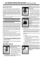
1
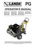
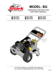
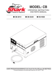
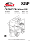
MODEL: BG
OPERATING INSTRUCTION
AND PARTS MANUAL
■ BG-3020
■ BG-3530
■ BG-3025
■ BG-3535
■ BG-3525
■ BG-5030
SHARK PRESSURE WASHERS ■ 4275 N.W. Pacific Rim Blvd. ■ Camas, WA 98607 ■ USA
For technical assistance or the Shark Dealer nearest you, call 1-800-771-1881.
2
MACHINE SPECIFICATIONS
●
Pump Volume At Pump Head:
BG-3020 3.0 GPM
BG-3025 2.8 GPM
BG-3525 3.6 GPM
BG-3530 3.5 GPM
BG-3535 3.3 GPM
BG-5030 4.8 GPM
●
Pump Pressure At Pump Head:
BG-3020 2000 PSI
BG-3025 2500 PSI
BG-3525 2500 PSI
BG-3530 3000 PSI
BG-3535 3500 PSI
BG-5030 3000 PSI
●
Machine Dimensions:
BG-3020
BG-3025
BG-3525
BG-3530
BG-3535
BG-5030
●
Shipping Weight:
BG-3020 255 Lbs.
BG-3025 255 Lbs.
BG-3525 255 Lbs.
BG-3530 255 Lbs.
BG-3535 255 Lbs.
BG-5030 255 Lbs.
Length = 39"
Length = 39"
Length = 39"
Length = 39"
Length = 39"
Length = 39"
Width =
Width =
Width =
Width =
Width =
Width =
31"
31"
31"
31"
31"
31"
Height =
Height =
Height =
Height =
Height =
Height =
35"
35"
35"
35"
35"
35"
3
CONTENTS
Introduction ............................................................. 4
Preventative Maintenance ...................................... 9
Machine Safety .................................................... 4-5
Oil Change Record ................................................. 9
Pre-Operation Check .............................................. 5
Storage ................................................................. 10
Set-Up Procedures ................................................. 5
Troubleshooting ............................................... 11-12
Component Identification ........................................ 6
Exploded View ...................................................... 13
Operating Instructions ............................................ 7
Exploded View, Parts List ................................ 14-15
Shut Down Procedures ........................................... 7
Hose & Spray Gun Assembly (All Models) ............ 16
General Washing Techniques ................................. 7
Warranty ............................................................... 17
How To Use the Detergent Injector ......................... 8
SERIAL NUMBER:
DATE PURCHASED:
FOR SALES AND SERVICE, PLEASE CONTACT:
Shark BG Manual • Form #97-6125 • Revised 2/02
4
BG SERIES PRESSURE WASHER
INTRODUCTION
Thank you for purchasing a Shark Pressure Washer.
This manual covers the operation and maintenance of the
BG-302031, BG-302531, BG-352531, BG-353031,
BG-353531, BG-503021, BG-302037, BG-302537,
BG-352537, BG-353037, BG-353537, BG-503021E and
BG-503027 washers. All information in this manual is based
on the latest product information available at the time of
printing.
Shark reserves the right to make changes at any time
without incurring any obligation.
The BG Series was designed for maximum
use of 8 hours per day, 5 days per week.
Owner/User Responsibility:
The owner and/or user must have an understanding of
the manufacturer’s operating instructions and warnings
before using this Shark pressure washer. Warning information should be emphasized and understood. If the operator is not fluent in English, the manufacturer’s instructions and warnings shall be read to and discussed with
the operator in the operator’s native language by the purchaser/owner, making sure that the operator comprehends its contents.
Owner and/or user must study and maintain for future
reference the manufacturers’ instructions.
The operator must know how to stop the machine quickly
and understand the operation of all controls. Never permit anyone to operate the engine without proper instructions.
This manual should be considered a permanent
part of the machine and should remain with it if
machine is resold.
When ordering parts, please specify model and
serial number.
MACHINE SAFETY
CAUTION: To reduce the risk of injury, read operating instructions
carefully before using.
1. Read the owner's manual thoroughly. Failure to follow instructions could cause malfunction
READ OPERATOR’S
of the machine and result in
MANUAL
death, serious bodily injury and/
THOROUGHLY
PRIOR TO USE.
or property damage.
2. All installations must comply with local codes. Contact your electrician, plumber, utility company or the
selling distributor for specific details.
WARNING
CAUTION
OPERATOR’S MANUAL
WARNING: Risk of asphyxiation
— Use this product only in a well
ventilated area.
3. Avoid installing machines in
small areas or near exhaust
fans. Exhaust contains poisonRISK OF
ous carbon monoxide gas;
ASPHYXIATION.
exposure may cause loss of
USE ONLY IN A WELL
VENTILATED AREA.
consciousness and may lead to
death. It also contains
chemicals known, in certain quantities, to cause cancer, birth defects or other reproductive harm.
WARNING: Flammable liquids
WARNING
can create fumes which can ignite
causing property damage or severe injury.
WARNING: Risk of fire — Do not
add fuel when the product is
operating.
RISK OF FIRE.
DO NOT ADD FUEL
WARNING: Risk of explosion —
WHEN OPERATING
MACHINE.
Do not spray flammable liquids.
4. Do not place machine near flammable objects as
the engine is hot.
5. Allow engine to cool for 2 minutes before refueling. If
any fuel is spilled, make sure the area is dry before
testing the spark plug or starting the engine. (Fire
and/or explosion may occur if this is not done.)
Refuel gasoline engines on mobile or portable
equipment:
a. outdoors;
b. with the engine on the equipment stopped;
c. with no source of ignition within 10 feet of the
dispensing point; and
d. with an allowance made for expansion of the fuel
should the equipment be exposed to a higher
ambient temperature.
In an overfilling situation, additional precautions are
necessary to ensure that the situation is handled in
a safe manner.
WARNING: High pressure stream
WARNING of water that this equipment can
produce can pierce skin and its
underlying tissues, leading to
serious injury and possible
amputation.
WARNING
HIGH PRESSURE
SPRAY CAN PIERCE
SKIN AND TISSUES.
BG SERIES PRESSURE WASHER
WARNING: High pressure spray
can cause paint chips or other
particles to become airborne and
fly at high speeds. To avoid personal injury, eye safety devices
must be worn.
PROTECTIVE
6. Eye safety devices and foot proEYEWEAR AND
CLOTHING MUST
tection must be worn when usBE WORN.
ing this equipment.
7. High pressure developed by these machines will cause
personal injury or equipment damage. Use caution
when operating. Do not direct discharge stream at
people, or severe injury or death will result.
8. Never make adjustments on machine while in operation.
9. Do not operate with spray gun in the off position for
extensive periods of time as this may cause damage to the pump.
10. The best insurance against an accident is precaution and knowledge of the machine.
11. Shark will not be liable for any changes made to our
standard machines, or any components not purchased from Shark.
12. Read engine safety instructions provided.
WARNING
WARNING
KEEP WATER
SPRAY AWAY FROM
ELECTRICAL
WIRING.
WARNING: Keep water spray
away from electrical wiring or fatal electric shock may result.
13. Never run pump dry or leave
spray gun closed longer than
5 minutes.
14. Do not allow children to operate the pressure washer at any
time.
15. Inlet water supply must be cold
and clean fresh water.
PRE-OPERATION CHECK
❑ Check pump oil level. (Use SAE 30W non-detergent
OPERATOR’S MANUAL
5
SET-UP PROCEDURES
1. Attach a 5/8" garden hose to inlet connector. Minimum flow should be 6 GPM.
2. Attach high pressure hose to discharge nipple using
quick coupler. Lock coupler securely into place by pulling back coupler collar and inserting it onto discharge
nipple, then pushing collar forward to lock in place.
Discharge
Nipple
Pressure Hose
Collar
Garden Hose
Filter
Inlet Connector
3. Attach variable pressure wand to spray gun using
teflon tape on threads to prevent leakage.
4. Attach swivel connector on discharge hose to spray
gun using teflon tape on threads.
5. Remove oil plug on top of pressure washer pump
and replace with dipstick supplied. (This may be
installed from the factory.)
Dipstick
6. Check oil level on sight glass on back of pump. Oil
should be visible one half way up sight glass (30W
non-detergent).
7. Fill gasoline tank and check engine oil.
oil). Dipstick is located on top of pump.
❑
❑
❑
❑
❑
❑
Cold water supply (minimum 6 GPM, 5/8", 20 PSI)
Filler Cap/Dipstick
Hose, wand, nozzle (nozzle size per serial plate)
Water filter (intact, non restrictive)
Upper Limit
Fuel (unleaded 86 or higher octane)
Open spray gun to relieve pressure before starting.
Engine oil (SAE 10W30)
Lower Limit
Notice: Running the engine with a low oil level can
cause engine damage.
6
BG SERIES PRESSURE WASHER
OPERATOR’S MANUAL
COMPONENT IDENTIFICATION
Starter
Grip
ON-OFF
Switch
High
Pressure
Nozzles
Unloader
Detergent Injector
Soap
Nozzle
Pump
Quick Coupler
Pressure Nozzle
Soap Nozzle
Wand
Coupler
Detergent Bucket
(not included)
Detergent
Hose
Wand w/Side
Grip
Trigger
Spray
Gun
High Pressure
Hose
Pump — Develops high pressure.
Starter Grip — Used for starting the engine manually.
Spray Gun — Controls the application of water and detergent onto cleaning surface with trigger device. Includes
safety latch.
Detergent Injector — Allows you to siphon and mix
detergents.
Inlet Connector
Water Filter
Water
Supply Hose
(not included)
High Pressure Hose — Connect one end to water pump
discharge nipple and the other end to spray gun.
Pump Protector — Cycles water through pump when
water reaches 140°F.
Note: If trigger on spray gun is released for more
than 2 minutes, water will leak from valve. Warm water
will discharge from pump onto floor. This system
prevents internal pump damage.
BG SERIES PRESSURE WASHER
OPERATING INSTRUCTIONS
1. Read provided engine manual warning and operating instructions.
2. Pull wand coupler collar
back and insert pressure
nozzle into coupler then
secure by pushing collar
forward to lock.
3. Turn on water at faucet and squeeze spray gun trigger allowing water to flow until a steady stream
comes out of wand.
Fuel Valve Lever
4. Move the fuel valve lever
to the ON position. Turn
the fuel valve lever to the
OFF position after stopping engine.
ON
OFF
5. To start a cold engine,
move the choke lever to
the CLOSED position.
To restart a warm engine, leave the choke
lever in the OPEN position.
OPERATOR’S MANUAL
7
9. With the spray nozzle pointed away from you or anyone else, press the trigger on the spray gun to obtain pressurized spray.
SHUTDOWN PROCEDURES
1. If a detergent injector was used, flush all lines with
clean water to remove soap residue.
2. Turn off engine. Turn off water supply.
3. Squeeze spray gun trigger to relieve any pressure.
4. Disconnect water supply hose from washer.
CAUTION: Do not allow pump to run without water.
5. Disconnect all hoses to allow water to drain. Protect
from freezing.
CAUTION: Do not allow pump to run longer than
3 minutes without water. Disconnect all hoses to
allow water to drain.
CAUTION: With machine off, open spray gun to
release pressure before removing discharge hose.
GENERAL WASHING
TECHNIQUES
Choke Lever
Test pressure and spray pattern on hard surface (i.e. cement) to gauge distance and impact of water spray.
OPEN
CLOSED
6. Turn the engine switch to
the ON position.
7. Open spray gun before pulling the starter grip.
Engine Switch
8. To start the engine pull
the starter grip lightly until you feel resistance,
then pull briskly. Return
the starter grip gently.
Hold spray nozzle
approximately one
foot from surface being cleaned. For best
surface cleaning action, spray at slight
angle.
Spray Nozzle
Wand
Wand
Quick Coupler
1 Foot
To change spray
nozzle for a different pattern it is recommended that you
turn off engine and squeeze spray gun trigger to release
hose pressure. Pull back on quick coupler at end of wand
and exchange nozzle. Make sure nozzle is seated securely. Restart engine.
Use the detergent injector to apply detergent. Wash from
the bottom and work up. Allow the detergent to set 5-10
minutes on surface. Rinse from top down.
NOTE: If pressure washer is running and not being
used for more than 2 minutes, turn off engine.
Starter Grip
CAUTION: Pull trigger on spray gun to relieve pressure if machine does not start after one pull of starter
grip.
CAUTION: Small engines may kick back. Do not hold
starter grip tightly in hand.
8
BG SERIES PRESSURE WASHER
HOW TO USE THE
DETERGENT INJECTOR
WARNING
SOME DETERGENTS
MAY BE HARMFUL
IF INHALED OR
INGESTED
WARNING: Some detergents may
be harmful if inhaled or ingested,
causing severe nausea, fainting
or poisoning. The harmful elements may cause property damage or severe injury.
The machine can siphon and mix detergents with the use of Shark's detergent injector kit.
1. Turn engine and water supply off. Squeeze spray
gun to relieve pressure before attaching detergent
injector.
OPERATOR’S MANUAL
2. To attach detergent injector between pressure
washer and high pressure hose, pull injector quick
coupler collar back and secure on discharge nipple.
Injector valve body arrow should point in direction of
flow.
3. Connect pressure discharge hose to injector nipple
securing quick coupler by pushing collar towards
nipple.
4. Start machine as outlined in Operating Instructions.
5. Place detergent pick-up tube into container of detergent solution.
6. Open spray gun. Water detergent ratio is approximately 15 to 1.
7. For clean up, place detergent pick-up tube into container of clear water and follow steps 5 and 6 to prevent detergent deposits from damaging the injector.
Detergent
Injector
Quick
Coupler
Collar
Discharge
Nipple
Water
Inlet
High Pressure Nozzle
Spray
Gun
Soap Nozzle
High Pressure
Hose
Detergent
Pick-up Tube
Trigger
Wand
w/Side Grip
BG SERIES PRESSURE WASHER
OPERATOR’S MANUAL
9
PREVENTATIVE MAINTENANCE
This pressure washer was produced with the best available materials and quality craftsmanship. However, you as the
owner have certain responsibilities for the correct care of the equipment. Attention to regular preventative maintenance procedures will assist in preserving the performance of your equipment. Contact your Shark dealer for maintenance. Regular preventative maintenance will add many hours to the life of your pressure washer. Perform maintenance more often under severe conditions.
MAINTENANCE SCHEDULE
Engine Oil
Inspect
Daily
Change
First month or 20 hours.
Every 100 hours or every 6 months after first month
Filter
Every 50 hours
Inspect
Every 50 hours
Clean
Monthly
Air Cleaner/Filter
Engine Fuel Filter
500 hours or 6 months
Spark Plug Maintenance
300 hours or annually
Clean Fuel Tank(s)
Annually
Replace Fuel Lines
Annually
Inspect
Oil level daily
Change
After first 50 hours, then every 500 hours or annually
Pump Oil
Replace High Pressure Nozzle
Every 6 months
Replace Quick Connects
Annually
Clean Water Screen/Filter
Weekly
Replace HP Hose
Annually (if there are any signs of wear)
Tighten
Every 6 months
Inspect/Replace
Every 6 months
Belts
OIL CHANGE RECORD
Check pump oil and engine oil level before first use of your new power washer.
Date Oil Changed
Month/Day/Year
Estimated Operating
Hours Since Last
Oil Change
Date Oil Changed
Month/Day/Year
Estimated Operating
Hours Since Last
Oil Change
10
BG SERIES PRESSURE WASHER
STORAGE
Pump Storage
CAUTION: Always store your pressure
washer in a location where the
temperature will not fall below 32°F
(0° C). The pump in this machine is
susceptible to permanent damage if
frozen. FREEZE DAMAGE IS NOT
CAUTION
COVERED BY WARRANTY.
If you must store your pressure washer in a location
where the temperature is below 32°F, you can minimize
the chance of damage to your machine by draining your
machine as follows:
1. Stop the pressure washer and detach supply hose
and high pressure hose. Squeeze the trigger of the
spray gun to drain all water from the wand and hose.
2. Restart pressure washer and let it run briefly (about
5 seconds) until water no longer discharges from
the high pressure outlet.
Engine Storage
When the pressure washer is not being operated or is
being stored more than one month, follow these instructions:
1. Replenish engine oil to upper level.
2. Drain gasoline from fuel tank, fuel line, fuel valve
and carburetor.
3. Pour about one teaspoon of engine oil through the
spark plug hole, pull the starter grip several times
and replace the plug. Then pull the starter grip slowly
until you feel increased pressure which indicates the
piston is on its compression stroke and leave it in
that position. This closes both the intake and exhaust
valves to prevent the inside of the cylinder from
rusting.
OPERATOR’S MANUAL
4. Cover the pressure washer and store in a clean, dry
place that is well ventilated away from open flame or
sparks.
NOTE: The use of a fuel additive, such as STA-BIL®,
or an equivalent, will minimize the formulation of fuel
gum deposits during storage. Such an additive may
be added to the gasoline in the fuel tank of the engine, or to the gasoline in a storage container.
After Extended Storage
CAUTION
Caution: Prior to restarting, thaw out any
possible ice from pressure washer hoses,
spray gun or wand.
Engine Maintenance
During the winter months, rare atmospheric conditions
may develop which will cause an icing condition in the
carburetor. If this develops, the engine may run rough,
lose power and may stall. This temporary condition can
be overcome by deflecting some of the hot air from the
engine over the carburetor area.
NOTE: Refer to the engine manufacturer's manual
for service and maintenance of the engine.
BG SERIES PRESSURE WASHER
OPERATOR’S MANUAL
11
TROUBLESHOOTING
PROBLEM
POSSIBLE CAUSE
SOLUTION
LOW OPERATING
PRESSURE
Insufficient water supply. Closed
faucet
Use larger garden hose; clean inlet water
screen. Open faucet.
Old, worn or incorrect spray nozzle
Match nozzle number to machine and/or
replace with new nozzle.
Plumbing or hose leak
Check plumbing system for leaks. Retape leaks
with teflon tape.
Faulty or misadjusted unloader
valve
Adjust unloader for proper pressure. Install
repair kit when needed. Call TUFF technical
support.
Worn packing in pump
Call TUFF technical support.
Machine has been stored in
freezing temperatures
Thaw out machine completely, including hose,
spray gun and wand.
Slow engine RPM
Call TUFF technical support.
Worn pump valves
Call TUFF technical support.
Dirt in pump valves
Call TUFF technical support.
Pump sucking air
Check all pump lines and connections.
Nozzle worn
Replace nozzle.
Unloader valve worn
Replace unloader valve.
ENGINE WILL NOT START
OR STOPS
WHILE OPERATING
Low oil shutdown
Fill engine with oil.
ENGINE IS
OVERLOADED
Nozzle partially blocked
Clean nozzle.
Excessive pressure from high
engine RPM
Adjust engine throttle to lower RPM.
WATER OR OIL LEAKING
FROM BOTTOM OF PUMP
A small amount of leaking is
normal
If excessive leaking occurs, call TUFF technical
support.
PRESSURE INCREASES
WHEN SPRAY GUN IS
CLOSED
Unloader valve not operating
properly
Call TUFF technical support.
PRESENCE OF WATER
IN PUMP OIL
Water sprayed at machine
Change oil. Direct spray away from machine.
High humidity in air
Check and change oil twice as often.
Piston packing worn. Oil seal worn
Call TUFF technical support.
FLUCTUATING
PRESSURE
PRESSURE LOW
AFTER PERIOD OF
NORMAL USE
12
BG SERIES PRESSURE WASHER
OPERATOR’S MANUAL
TROUBLESHOOTING
PROBLEM
POSSIBLE CAUSE
SOLUTION
OIL SQUIRTS OUT OF
OIL CAP ON PUMP
Pump over filled with oil
Maintain oil level at red dot on sight glass at rear
of pump or at top of notch on dipstick.
ENGINE OPERATES
FOR 15 MIN. THEN
STOPS
Not enough gas or engine oil
Fill tank with gas. Check oil level.
Vapor lock developed by heat of
day
Keep gas tank full to avoid vapor locking.
Obstruction in fuel filter
Clean or replace fuel filter.
Piston packing worn
Call Shark technical support.
O-Ring plunger retainer worn
Call Shark technical support.
Cracked piston
Call Shark technical support.
OIL DRIPPING
Oil seal worn
Call Shark technical support.
WATER LEAKING
FROM PUMP
PROTECTOR
Spray gun closed with machine
running 2 minutes or longer
Open spray gun or turn off machine.
Excess water supply pressure
Place a pressure regulator at end of 50' garden
hose.
WATER DRIPPING
FROM UNDER PUMP
BG SERIES PRESSURE WASHER
OPERATOR’S MANUAL
13
EXPLODED VIEW
ALL MODELS
22
3
2
47
1
43
8
42
23
42
9
44
50
30
45
49
28
26
34
18,19
46
33
49
48
13
27
4
20
29
35
19
10
36
18
15
32
51
16
52
53
17
12
11
17
18
31
31
6
5
25
4
36
7
24
10
21
18
11
39
37
41
14
38
20
14
BG SERIES PRESSURE WASHER
OPERATOR’S MANUAL
EXPLODED VIEW PARTS LIST
ITEM
1
PART NO.
5-0105
Engine, Honda, 11 HP (353031) 1
Engine, Honda, 13 HP (353531)1
5-0306
Engine, Vanguard, 16 HP
Pull/Start (503021)
DESCRIPTION
5
4-12803540
Nozzle, SAQCMEG, 4003.5
White (3535, 3020)
QTY
1
4-12804000
Nozzle, SAQCMEG, 0004 Red
(3530, 3020)
1
1
4-12804015
5-0104
Engine, Honda, 5.5 HP
(302031)
Nozzle, SAQCMEG, 1504 Yellow
(3530, 3020)
1
1
4-12804025
Engine, Honda, 6.5 HP
(302531)
Nozzle, SAQCMEG, 2504 Green
(3530, 3020)
1
1
4-12804040
▲ Guard, Muffler, Vanguard
16 HP Only
Nozzle, SAQCMEG, 4004 White
(3530, 3020)
1
1
4-12805500
▲ Muffler, Vanguard
16 HP Only
Nozzle, SAQCMEG, 005.5 Red
(5030)
1
1
4-12805515
▲ Heat Deflector,
Vanguard Only
Nozzle, SAQCMEG,
1505.5 Yellow (5030)
1
1
4-12805525
Pump, General, EZ2542S
(302531, 302031, 352531)
Nozzle, SAQCMEG,
2505.5 Green (503021)
1
1
4-12805540
Pump, General, TS-1011
(353031, 353531)
Nozzle, SAQCMEG
4005.5 White (503021)
1
1
6
4-16540
Nozzle, Compl, QCEM-6540
w/Black Nylon
1
1
7
90-2007
▲ Nut, 3/8", HEX, NC
2
8
2-2007
Nipple, 3/8" x 3/8"
NPT ST Male (General Pumps) 1
2-2006
Nipple, 3/8" x 3/8" FNPT ST.
(Legacy Pumps)
1
95-07101214
5-23130
5-23040
5-2307
5-1625
5-1649
5-1650
5-1651
5
PART NO.
Engine, Honda 9 HP (352531) 1
76-807964
4
ITEM
5-0102
95-07101149
3
QTY
5-010721
5-01041
2
DESCRIPTION
Pump, General, TS-2021
(503021)
Pump, Legacy WML-2540
(302037, 302537)
1
Pump, Legacy TML-3045
(352537, 303077, 353037)
1
Pump, Legacy TML-3545
(353537)
1
Pump, Legacy TML-3053
(503027)
1
9
2-30082
Pump Protector, 1/2" PTP
1
10
90-4002
Washer, 3/8", SAE, Flat
14
11
90-4001
Washer, 5/16", Flat SAE
16
12
95-07200100
Frame Assy (5030)
1
95-07200101
Frame Assy (3020, 3025,
3525, 3530, 3535)
1
Belt Guard (3530, 3535,
5030)
1
5-3025
Unloader, PA 8 GPM/3650 PSI
(353031, 353531, 503021)
1
5-3022
Unloader, PA 8 GPM, 3650 PSI
(302031, 302531, 352531)
1
5-3151
Unloader, APR 53000 (302037,
302537, 352537, 353037)
1
2-011727
▲ Belt Guard
(3020, 3025, 3525)
1
5-3152
Unloader, APR 35
(353537, 503027)
1
90-19710
▲ Screw, 1/4" x 3/4" HH NC,
Whiz Loc
6
Wheel & Tire, 6" Steel Rim
(503021)
2
90-20231
▲ Nut, Cage, 1/4" x 12 GA
6
95-07200023
Handle Assy, Grab
1
11-0307
▲ Label, Nozzle/Inst Plate
1
4-0307
4-0303
Wheel & Tire, 4" Steel Rim
(3020, 3025, 3525, 3530, 3535) 2
4-12803500
Nozzle, SAQCMEG, 003.5 Red
(3535, 3020)
1
4-12803515
Nozzle, SAQCMEG, 1503.5
Yellow (3535, 3020)
1
Nozzle, SAQCMEG, 2503.5
Green (3535, 3020)
1
4-12803525
13
14
2-011721
BG SERIES PRESSURE WASHER
OPERATOR’S MANUAL
15
EXPLODED VIEW PARTS LIST (CONT)
ITEM
PART NO.
DESCRIPTION
QTY
ITEM
PART NO.
DESCRIPTION
QTY
15
95-07200026
Handle, Bumper
1
31
95-07102101
Tab, Belt Guard Mount
16
90-10220
Bolt, 3/8" x 3-1/2", TAP
2
32
95-07101012
Axle, 5/8" Rod, 27"L (503021) 1
17
90-10072
Bolt, 5/16" x 2",
NC Carriage Zinc
95-07102225
8
Axle, Rhino, Hot Box (302031,
302531, 352531, 353031,
353531)
1
3
18
90-2001
Nut, 5/16", ESNA, NC
12
19
90-2002
Nut, 3/8" ESNA, NC
10
33
11-3229
Label, Belt Guard
1
20
90-20041
Collar, 5/8" Bore Shaft 3010
2
34
11-0101
Label, Warning (Lexan)
1
21
90-2020
Nut, Cage, 3/8" x 12 GA
2
35
95-07200103
Rail, Pump
1
22
10-02025A
Label, "Hot/Caliente" with
Arrows Warning
36
90-4005
Washer, 5/8" Flat
2
1
37
95-07101135
Bracket, Belt Tension
1
1
38
90-1010
Bolt, 5/16" x 1-3/4"
(Vanguard Engine)
4
901020
Bolt, 3/8" x 2", NC HH
(Honda Engine)
4
Bolt, 3/8" x 1-1/4" NC, HH
6
23
10-02029
Label, Danger Cool Engine
24
2-0103
Grommet, Rubber,
Nozzle Holder
5
2
25
2-01041
Pad, Soft Rubber, 50 Duro
26
5-40203001
Pulley, 2AK 30H (353031,
353531, 353037, 352537)
5-40203401
Pulley 2AK 34H (352531)
5-40402775
Pulley BK 27 x 3/4" Bore
(302031, 302531)
1
Pulley, 2BK 32H
(302031, 302531)
1
5-40503201
Pulley 2BK 32H (503021)
1
5-40207401
Pulley, 2AK 74H (353031,
353531, 352531)
1
5-40403201
27
28
29
30
39
90-1017
1
40
90-40125
▲ Washer, 3/8" x 1"
2
1
41
90-4007
Washer, 3/8" x 1-1/2"
4
42
2-0031
Elbow, 3/8" Street
2
43
2-10942
Swivel, 1/2" x 3/4" GHF
1
44
2-1923
Strainer, 1/2" Inline
1
45
2-3100544
Valve, E-Z Start
1
46
2-1084
Hose Barb,
1/4" Barb x 1/8" MNPT
1
Hose Barb, 90°,
1/4" Barb x 1/8" MNPT
(General Pumps)
1
Hose Barb, 90°,
1/4" Barb x 1/4" MNPT
(Legacy Pumps)
1
47
2-1088
5-40407501
Pulley, BK 75 (302031, 302531) 1
5-40508001
Pulley, 2BK 80H (503021)
1
5-40208401
Pulley, 2AK84H (352537)
1
5-40409001
Pulley, BK 90 (302031, 302531) 1
5-511100
Bushing H x 1"
(All Except 302031, 302531)
1
48
Bushing, H x 24mm
1
49
2-9000
Clamp #4 Screw
2
2-1024
Elbow, 1/2" Street, Brass
1
1
5-512024
2-1089
4-02100000
Hose, 1/4"
1 FT
5-602035
Belt, AX35 (353031, 353531)
2
50
5-604035
Belt, BX35 (302031, 302531)
2
51
95-07101114
Clamp, Battery (503021E)
5-602037
Belt, AX37 (352531)
2
52
90-1019
5-604036
Belt, BX36 (503021)
2
Bolt, 3/8" x 1-3/4", Tap
(503021E)
2
5-602038
Belt AX38 (352537)
2
53
95-07101113
Holder, Battery (503021E)
1
▲ Not Shown
16
BG SERIES PRESSURE WASHER
OPERATOR’S MANUAL
HOSE & SPRAY GUN ASSEMBLY
ALL MODELS
4
7
3
1
5
Pressure Nozzle
6
Brass Soap
Nozzle
2
ITEM
1
2
QTY
ITEM
PART NO.
DESCRIPTION
QTY
PART NO.
DESCRIPTION
2-2002
Coupler, 3/8" Female
1
5
2-0123H
▲ Quick Coupler O-Ring,
1/4" & 3/8" (Packaged)
1
6
4-16540
Brass Soap Nozzle
1
7
2-2000
Coupler, 1/4" Female
1
2-0119
1
Pressure Nozzle
(See Exploded View)
4-02093450BC Hose w/Coupler
(All Models Except 353531)
1
4-02073450RC Hose w/Coupler (353531)
1
▲ O-Ring, Coupler Quick Sm
HI-HT
▲ Not Shown
3
4-01246
Spray Gun, AP 1000
1
4
4-0110413
Wand, Side Grip, w/Coupler
1
BG SERIES PRESSURE WASHER
WARRANTY
SHARK LIMITED NEW PRODUCT WARRANTY
PRESSURE WASHERS
WHAT THIS WARRANTY COVERS
All SHARK PRESSURE WASHERS are warranted by SHARK to the original purchaser to be free from defects in materials and
workmanship under normal use, for the periods specified below. This Limited Warranty is subject to the exclusions shown below,
is calculated from the date of the original purchase, and applies to the original components only. Any parts replaced under this
warranty will assume the remainder of the part’s warranty period. This warranty applies to the orignial purchaser and is not
transferable.
LIMITED LIFETIME PARTS WARRANTY:
Components manufactured by SHARK, such as frames, handles, coil wraps, float tanks, and belt guards. All heating coils will
have a one year warranty. Internal components on the oil-end of all pressure washer pumps will have a seven year warranty.
ONE YEAR PARTS WARRANTY:
All other components, excluding normal wear items as described below, will be warranted for one year on parts. Warranty on
these parts will be for one year regardless of the duration of the original component manufacturer’s part warranty.
WARRANTY PROVIDED BY OTHER MANUFACTURERS:
Motors, generators, and engines, which are warranted by their respective manufacturers, are serviced through these manufacturers’ local authorized service centers. SHARK cannot provide warranty on these items.
WHAT THIS WARRANTY DOES NOT COVER
This warranty does not cover the following items:
1. Normal wear items, such as nozzles, guns, discharge hoses, wands, quick couplers, seals, filters, gaskets, O-rings,
packings, pistons, pump valve assemblies, strainers, belts, brushes, rupture disks, fuses, pump protectors.
2. Damage or malfunctions resulting from accidents, abuse, modifications, alterations, incorrect installation, improper
servicing, failure to follow manufacturer’s maintenance instructions, or use of the equipment beyond its stated usage
specifications as contained in the operator’s manual.
3. Damage due to freezing, chemical deterioration, scale buildup, rust, corrosion, or thermal expansion.
4. Damage to components from fluctuations in electrical or water supply.
5. Normal maintenance service, including adjustments, fuel system cleaning, and clearing of obstructions.
6. Transportation to service center, shop labor charges, field labor charges, or freight damage.
WHAT YOU MUST DO TO OBTAIN WARRANTY SERVICE
While not required for warranty service, we request that you register your SHARK pressure washer by returning the completed
registration card. In order to obtain warranty service on items, you must return the product to an Authorized SHARK Dealer,
freight prepaid, with proof of purchase, within the applicable warranty period. If the product is permanently installed, you must
notify your Authorized SHARK Dealer of the defect. The Authorized Dealer will file a claim, which must subsequently verify the
defect. In most cases, the part must be returned to SHARK freight prepaid with the claim. For warranty service on components
warranted by other manufacturers, the Authorized Dealer can help you obtain warranty service through these manufacturers’
local authorized service centers. If you are unable to resolve the warranty claim satisfactorily, write to SHARK at 4275 N.W.
Pacific Rim Blvd., Camas, WA 98607, ATTN: Warranty Dept., detailing the nature of the defect, the name of the Authorized
Dealer, and a copy of the purchase invoice.
LIMITATION OF LIABILITY
SHARK’S liability for special, incidental, or consequential damages is expressly disclaimed. In no event shall SHARK’S liability
exceed the purchase price of the product in question. SHARK makes every effort to ensure that all illustrations and specifications are correct, however, these do not imply a warranty that the product is merchantable or fit for a particular purpose, or that
the product will actually conform to the illustrations and specifications. THE WARRANTY CONTAINED HEREIN IS IN LIEU OF
ALL OTHER WARRANTIES, EXPRESS OR IMPLIED, INCLUDING ANY IMPLIED WARRANTY OF FITNESS FOR A PARTICULAR PURPOSE. SHARK does not authorize any other party, including authorized Dealers, to make any representation or
promise on behalf of SHARK, or to modify the terms, conditions, or limitations in any way. It is the buyer’s responsibility to ensure
that the installation and use of SHARK products conforms to local codes. While SHARK attempts to assure that its products
meet national codes, it cannot be responsible for how the customer chooses to use or install the product.
SHARK PRESSURE WASHERS
4275 N.W. Pacific Rim Blvd. • Camas, WA 98607 • USA • 1-800-771-1881
N.W. Pacific Rim Blvd. • Camas, WA 98607 • 1-800-771-1881
Form #97-6125 • Revised 2/02 • Printed in U.S.A.