1
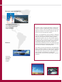
Over a century of history at the service of technology
Mitsubishi Heavy Industries Ltd is the founder of the Mitsubishi Group, one
of the major industrial and financial empires in the world, with a network
of as many as 131 industries.
The origin of the brand dates back to the last decade of the nineteenthcentury in Nagasaki, where the first big shipyard was established to produce
ships for the Japanese navy. Shipbuilding is still one of the most important
sectors for Mitsubishi Heavy Industries. Subsequently Mitsubishi implemented
a progressive diversification and extension of its activity in heavy industry,
as well as in the airplane, rail and car sectors, becoming the biggest private
company in Japan in the 1930s. Mitsubishi Heavy Industries still operates
in the car sector through its controlled company Mitsubishi Motors.
In the post-war period there was a progressive process of corporate
downsizing by American industry for the protection of the same.
The competitor Mitsubishi Electric was set up in 1921 as one of these spin
offs, producing a limited number of products (electrical engines for boats
and fans) and keeping the three-pointed diamond as its logo, just like the
parent company.
Today, Mitsubishi Heavy Industries is still a leader in numerous sectors of
traditional industry, but its also one of the major movers of technological
innovation in the aviation, aerospace, robotics and renewable energy sectors.
The current need for alternative energy resources in fact, sees Mitsubishi
Heavy Industries constantly committed to searching for state-of-the-art
solutions that can preserve the delicate balance of the ecosystem both
today and in the future.
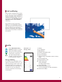
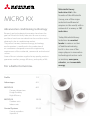
Future and technology for air conditioning
Research and technological innovation have been the companys goals
for over a century, and translate into the excellent results that have
been obtained in the air conditioning market.
The perfect balance between energy, technology and development
this is what we strive for in the production of air conditioning units
designed to meet the plant engineering requirements of the civil, tertiary
and industrial sectors.
State-of-the-art solutions applied to high quality products, that guarantee
wellbeing, energy saving and living quality.
For a better tomorrow.
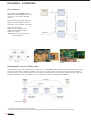
Global Mitsubishi Heavy Industries activity
2
Resources/Energy
Environment
Industrial
raw oil storage base
liquid natural gas tanks
boilers and turbines
oil production plants
thermal power plants
combined cycle plants
solid oxide fuel cells
water and wind turbines
biomass synthesis systems
nuclear power plants with pressurised water
reactors
uranium enrichment systems
fast breeder reactors
co-generation systems
ultra-high steel smokestacks
refuse incineration plants
night soil treatment plants
electrostatic precipitators
fluidized incinerators
CFC collecting equipment
spillway radial gates
dams
steel bridges
desalination plants
distribution and logistics equipment
engines
wiring and cabling systems
Transportation
Industry
unloader&container cranes
integrated automated storage systems
rubber and tyre machineries
suspended monorail systems
skyrails
forklift trucks
helicopters
aircraft
container ships
railway maintenance equipments
LNG carrier
chemical plants
wind tunnels/test equipments
casting machines
strip mills
cement plants
industrial robotics
injection moulding machines
pulp&paper machinery
corrugating machines
boxmaking machines
machine tools
printing machines
Comfort
air conditioners for residential and
commercial applications
automotive air conditioners
refrigeration units
dry cleaning machines
food machinery
cruise ships
multipurpose domes
Research and development
oceanographic research ships
deep submergence research vehicles
communication satellite rockets
space transportation
rockets and engines
Defence
By land or sea, in the sky and also in space: the
range of interest of Mitsubishi Heavy Industries
knows no limits, with the production of over 700
different products for various industrial and civil
sectors on the international market.
Ships, civil engineering, power stations, industrial
and civil machines, air conditioning units, pollution
reduction and environmental control systems,
aerospace systems: the rich and varied range of
Mitsubishi Heavy Industries products is designed
to make the environment liveable and harmonious.
This balance derives from over a century of
technological leadership which has made the brand
famous worldwide for high end products, as result
of constant research and development.
The advent of the third millennium saw Mitsubishi
Heavy Industries venture into sectors of the greatest
importance for the future of the planet: research
into alternative energy sources, space exploration,
with constant commitment to guarantee
development with man and technology in perfect
harmony.
submarines
naval vessels
jet fighters
helicopters
missiles
3
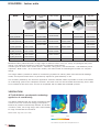
Technological evolution
The Mitsubishi Heavy Industries
research laboratories have always put
the study and application of new
technologies at the forefront, to
support the product development of
the highest quality, respecting the
environment and creating airconditioned solutions.
Mitsubishi Heavy Industries air
conditioning units use mainly PAM
DC Inverter technology, which
guarantees higher efficiency and
energy saving, with the possibility of
reaching the required temperature
faster and with greater precision.
Technological research has also made
it possible to develop high performance
products, with very high market values
for each class of product.
The studies on the airflow distribution
and the application of methods of
aerodynamic analysis used in the Jet
engines design has led to the
development of Jet Air Scroll
technology which guarantees even
temperature, silent running and high
air quality in air-conditioned areas.
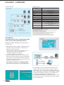
Technological evolution for the greatest
flexibility of use and simplified
Caring for the environment
Air quality for a better future: this is
the mission of Mitsubishi Heavy
Industries, which boasts Energy
Efficiency Rating A for most of its
products.
All products use R410A, an ecofriendly bi-component CFC-free gas,
which guarantees the maximum
efficiency and economic management
thanks to the possibility of partial
recharging.
As the recent application of RoHs
standards on the European market
involves restrictions on the use of
some harmful substances for the
4
environment, Mitsubishi Heavy
Industries increased its efforts to search
for eco-compatible solutions.
This resulted in the development of
the PbF propriety method, which
allows for the production of electronic
boards welded using materials that
do not contain lead, guaranteeing total
quality and reliability.
maintenance: sophisticated and practical
centralized control instruments make it
possible to extend the number of units
and systems that can be controlled, for
a rational and secure management.
Total wellbeing
Ideal climatic conditions every month
of the year; functional and detailed
design; air quality; silent running and
maximum energy saving. These are
the features that Mitsubishi Heavy
Industries offers for the desired
wellbeing.
All products of the range have
filtering and air purifying systems
that can clean the air in the room to
prevent allergies and respiratory
diseases, contrasting and completely
destroying the formation of bacteria
and mould.
Quality
All the Mitsubishi Heavy
Industries products are ISO
9001 and 14001 certified
and are part of the Eurovent
certification programme.
The CE marking makes it
possible to sell the products
on the European market.
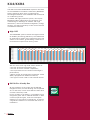
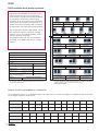
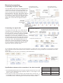
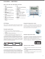
Energy labelling
According to EU standards, since
2004 air conditioning units up to 12
kW refrigerating power must have
an Energy label. This is mainly to
classify the level of consumption on
the basis of the ratio between
thermal performance and energy
consumption.
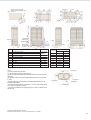
Example of
Energy Label
1
3
4
5
6
7
8
9
10
11
12
13
2
1
2
3
4
5
6
7
8
9
10
11
12
13
Energy.
Air conditioner.
Manufacturer.
Outdoor Units-Indoor Units.
Low consumption.
High consumption.
Annual energy consumption, kW/h in cooling
mode.
Cooling output kW.
Energy efficiency ratio.
Type: cooling only;
cooling & heating;
air cooling; water cooling.
Heat output (kW).
Heating mode performance
A: low consumption; G: high consumption.
Noise level in dB(A).
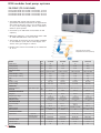
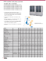
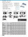
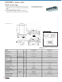
5
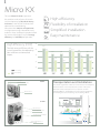
KX4/KXR4
The VRF Inverter KX4/KXR4 Multi-system is the result
of the standards of excellence reached by Mitsubishi
Heavy Industries after years of impassioned
technological research in the residential and commercial
air conditioning sector.
A reliable and highly efficient system, which puts
Mitsubishi Heavy Industries at the forefront in air
conditioning for buildings of medium and large
dimensions, where centralised management, energy
savings, and the functionality of the control devices
are essential elements.
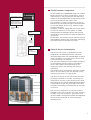
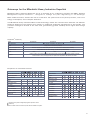
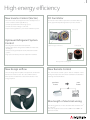
High COP
KX4
The KX4/KXR4 system reaches the highest levels
of reliability and energy efficiency: the coefficients
of performance (COP) of the range have first rate
values in the market, guaranteeing a reduction in
environmental impact and running costs.
3,93 4,18
3,91
3,39
3,81
3,84
3,82
3,73
3,55
3,52
3,47
3,42
3,69
3,25
3,83
3,73
3,02
2,72
We can reach such high COP values thanks to:
the use of R410A refrigerating gas;
the use of the DC Inverter compressor;
the improvement of the external exchangers
performance;
better control of the electronic expansion valves
(EEV), equipped with additional sensors;
the type of motor used on the external DC fan.
R410A Eco-friendly Gas
All the products of the range use the R410A
refrigerant which, as well as being eco-compatible
as it is CFC-free, is also more effective than other
coolants commonly used.
In fact, thanks to its density, its possible to use
refrigerant pipes with a reduced diameter in both
circuits (liquid and gas), with the consequent
reduction in the volume of refrigerant, as well as
a significant reduction in the times and costs of
installation.
6
3,99
3,84
3,82
3,83
3,82
3,73
3,71
3,78
3,72
3,71
3,73
3,64
3,47
3,55
3,47
3,51
3,43
3,33
3,28
3,14
3,03
2,87
3,83
2,72
The DC Inverter compressor
Improved efficiency of the
support
Tolerance in the production
of reduced mechanical
elements, thanks to the use
of highly resistant materials
Reduced refrigerant
leakage
Improved mechanical
efficiency
Reduction of
compressor
diameter
Reduced
lubricant
leakage
All the models of the KX4/KXR4 range use variable
speed control DC Inverter compressors, with an
improvement in the performance and efficiency
thanks to the self-adjustment of the output to suit
the actual demand of the indoor units.
The possibility of leaks of refrigerant or lack of
lubrication for the axial bearings is reduced thanks
to the new design of the scroll, made of highly
resistant materials.
A magnet is used to engage the rotor of the motor
to improve efficiency at low speed. The IPM
(Intelligent Power Module) device and the high
voltage drive motor further increase the efficiency
of the unit.
Furthermore, the Inverter control reduces start-up
and shutdown times on each compressor, balancing
the operating hours between the same.
Improved efficiency of the
motor
Using a reluctance
motor with a
permanent magnet
Fan
Heat exchanger
Airflow chamber
Control box
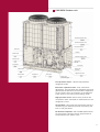
State-of-the-art technologies
The DC Inverter motor is equipped with fans
designed by the Mitsubishi Heavy Industries
aerospace department, the serrated edges of which
make it possible to increase the air volume with
a reduced energy consumption.
The electronic expansion valves adapt constantly
to the operating speed, making it possible to
control the pressure and expansion of the
refrigerant, both in the heating and cooling
operations.
The presence of an accumulator stores the coolant
that is not used during the low-demand cycles,
optimizing the flow in the gas phase.
The fans on the top of the unit extend the heat
exchanger surfaces on 4 sides, optimizing the
performance. Access to the sensors of the heat
exchangers for the relevant maintenance operations
is easy thanks to the fully accessible front with
the pipes connecting the condensers at the front
of the unit.
The vertical configuration of the fans makes it
possible to duct the air outlet at a static pressure
of 50Pa in normal conditions. The indoor units
can be located in closed environments and equipped
with an external ducted air outlet through a
ventilation slot.
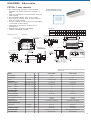
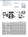
7
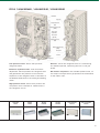
KX4/KXR4
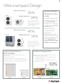
Ultra-compact Design
The compact design of the outdoor units of the
KX4/KXR4 series is unmatched, as all models from
8HP to 24HP have the same structural
characteristics. The design and the reduced footprint
dimensions make it possible to find a solution to
many limits often dictated by the space available
for installation. These characteristics, as well as
guaranteeing the optimization of spaces and the
installation work, also make it possible to
interchange with other models of the Mitsubishi
Heavy Industries range, leaving space for the
installation of other equipment.
The KX4/KXR4 units can also be incorporated in
previous KX2 series installations, without having
to change the basic structure, as the width and
depth are compatible with the previous (KX-KX2
8-10HP) models.
Same footprint for models from 8 to 24HP
Refrigerant piping
The refrigerant pipe lengths permitted for the
KX4/KXR4 series are the longest on the market:
with up to 160 m for each single module and a
total length of 510 m on the 8 - 24HP models.
This characteristic allows greater flexibility in the
planning and development phase of the air
conditioning system.
Thanks to the separation of the exchanger and
compressor compartments the refrigerant pipes
can easily be laid out in each of the four directions.
The possibility of installing the refrigerant
connections on the back of the unit makes
installation in series easier and increases the front
space optimizing the management of servicing and
maintenance operations.
1m
15 m
50 m
Reduced installation space
The reduction of the installation spaces required,
thanks to the ultra-compact design and the
availability of single modules up to 24HP, is also
determined by the possibility of being able to install
the units in series, in other words without any
space between one machine and the next.
Installation in series guarantees an excellent
aesthetic result, leaving space for other installations,
functional or in series, and permits to replace parts
and update the plant at a later date, in the same
space as was originally set aside for the plant.
8
Drain pipe
Outdoor
All the outdoor units from 8 to 24HP
have the same footprint and lateral
dimensions. This characteristic makes
it easy to install several combined
outdoor units.
Up to 50 Pa
Indoor
Floor
Outdoor unit
Easy to transport
The units are fitted with a practical base which
makes it easy to lift and transport them; no wooden
pallet is required, just a forklift truck, a hoist or
slings passing through the holes in the base.
Furthermore, as there is no difference between
master and slave units, no special components
are required, nor is any particular transportation
and positioning of the unit, making the installation
work fast and easy.
Easy service and maintenance
Airflow chamber
Control box
7-segment display
Fault LED indicator (red)
RS232C connector
Normal LED indicator (green)
To check the functional and operational state of
the system simply connect a Laptop to the outdoor
unit. Any problem solving is made faster thanks
to the possibility of gathering the operating data
both when the machine is running and in the case
of an error, and when the unit is in a test phase.
The data can be downloaded and analysed
statistically using the optional software programme.
The values and parameters of any errors can be
displayed on a large display.
The test mode can be activated with a switch on
the electronic board of the outdoor unit, to check
for any installation errors.
In the case of a fault on one of the 2 compressors
(14 - 24HP models for single units and for all
combined units), the system automatically goes
into emergency mode, with just one compressor
running to avoid the total shutdown of the plant,
guaranteeing operational continuity. In the case
of an anomaly, the operating parameters relevant
to the 30 minutes before the problem arose are
saved automatically, making diagnostics and faultfinding fast and easy.
Service LED indicator (green)
Unit address selector (tens)
Unit address selector (units)
Graph 1
Frequency
Time
Graph 2
Current
Time
Using the relevant software (Mente PC) it is possible to create reports with operating data
and any anomalies.
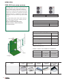
9
KX4/KXR4
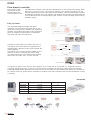
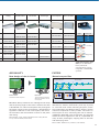
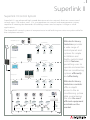
The Superlink® centralized control system
The exclusive Mitsubishi Heavy Industries Superlink
fast data transmission system, which in the past
was only dedicated to highly sophisticated systems,
is used today to connect residential and commercial
air conditioning units in a network and control
them from a remote station, optimising the
management of small, medium and large surfaces.
Up to 48 units can be connected in a network per
line, and controlled from a remote station.
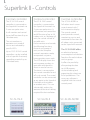
The wide range of individual and centralized
controls, and the possible combined use, makes
it possible to develop differentiated modular systems
for each control zone.
The use of Superlink reduces the wiring required,
thanks to a cable with 2 non-polarized wires: when
the plant is designed this makes integrated planning
simple with a significant reduction in the installation
costs.
RS232C connector
10
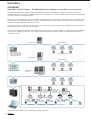
Monitoring the operating functions from a remote computer
KX4/KXR4 Outdoor unit
Electronic expansion valve
Electronic expansion valve
Low-pressure sensor
Control box
Receiver
Solenoid valve
Electronic expansion valve
Solenoid valve
Service valve
Gas side
Compressor 1
Accumulator
Service valve
Liquid side
Solenoid valve
Solenoid valve
Compressor 2
High-pressure sensor
4-way valve
Service valve
(oil equalising pipe)
Low-pressure sensor: device that prevents
refrigerant leaks.
Electronic expansion valve: with continuous
adjustment, this optimizes the refrigerant flow and
guarantees the pressure control and the expansion
of the coolant flow on the basis of the different
loads, both in the cooling and heating mode.
High-pressure sensor: device that protects the
compressor from overloads or malfunctions in the
refrigerant circuit.
Accumulator: this stores the refrigerant that isnt
used during low demand periods, optimising the
flow in the gas phase.
DC Inverter compressor: with variable speed control,
so the output is always exactly proportional to
the demand of the indoor units.
11
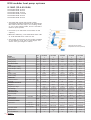
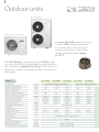
KX4
KX4 modular heat pump systems
Heat pump units
Thanks to its compact and modular
characteristics the KX4 series heat pump
system meets the new air conditioning
requirements of medium and large buildings
to perfection, with cooling and heating
operation of all the indoor units connected.
The system can condition a single flat or a
whole multi-storey building, and is suitable
for particularly vast open space environments.
The range starts with an 8HP model, up to
the maximum capacity value for a single
outdoor unit on the market (24HP), with a
cooling capacity of 68 kW.
The outdoor units can also be combined
providing up to 48HP/136 kW on a single
system.
8HP
10HP
FDCA224HKXE4R*
FDCA280HKXE4R*
12HP
DIS-180-1
DIS-371-1
DIS-540-1
Total capacity of the I.U. downstream of the branch
<18 kW
>18 kW - <37,1 kW
>37,1 kW - <54 kW
>54 kW
Header set (opt.)*
HEAD4-22-1R
HEAD6-180-1R
HEAD8-371-1R
HEAD8-540-1R
Combinations of heat pump units
Branch piping set (opt.)
Max. branches
<18 kW
4
>18 kW - <37,1 kW
6
>37,1 kW - <54 kW
16HP
18HP
20HP
22HP
24HP
FDCA504HKXE4R
FDCA560HKXE4R
FDCA615HKXE4R
FDCA680HKXE4R
28HP
FDCA735HKXE4R
FDCA800HKXE4R
(FDCA335HKXE4R-K+FDCA400HKXE4R) (FDCA400HKXE4R+FDCA400HKXE4R)
32HP
FDCA900HKXE4R
(FDCA450HKXE4R+FDCA450HKXE4R)
38HP
FDCA1065HKXE4R
(FDCA504HKXE4R+FDCA560HKXE4R)
34HP
FDCA960HKXE4R
(FDCA450HKXE4R+FDCA504HKXE4R)
40HP
FDCA1130HKXE4R
(FDCA560HKXE4R+FDCA560HKXE4R)
30HP
FDCA850HKXE4R
(FDCA400HKXE4R+FDCA450HKXE4R)
36HP
FDCA1010HKXE4R
(FDCA504HKXE4R+FDCA504HKXE4R)
42HP
FDCA1180HKXE4R
(FDCA560HKXE4R+FDCA615HKXE4R)
8
>54 kW
8
Outdoor unit branch piping set **
DOS-2A-1
FDCA400HKXE4R
FDCA450HKXE4R
26HP
DIS-22-1
14HP
FDCA335HKXE4R*
FDCA335HKXE4R-K
44HP
for 2 units (from 735 to 1360)
FDCA1235HKXE4R
(FDCA615HKXE4R+FDCA615HKXE4R)
46HP
FDCA1300HKXE4R
(FDCA615HKXE4R+FDCA680HKXE4R)
48HP
FDCA1360HKXE4R
(FDCA680HKXE4R+FDCA680HKXE4R)
* These models of outdoor units arent modular, therefore they
can only be used in stand-alone mode. For the 26HP combination
(14HP+12HP) must be used the outdoor unit
FDCA335HKXE4RK.
* Cannot be connected to FDUA 224 and 280 model headers.
**To use only with 2 combined outdoor units and not for a
stand-alone installation.
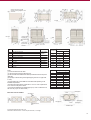
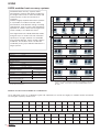
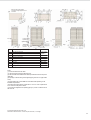
Number of indoor units available for combinations
Up to 48 indoor units, of 12 different types and capacities, for a total of roughly 61 models can be connected
to the higher capacity outdoor unit.
HP equivalent
Model
N. of connectable units
HP equivalent
Model
N. of connectable units
12
8
10
12
14
16
18
20
22
24
26
28
FDCA224HKXE4R FDCA280HKXE4R FDCA335HKXE4R FDCA400HKXE4R FDCA450HKXE4R FDCA504HKXE4R FDCA560HKXE4R FDCA615HKXE4R FDCA680HKXE4R FDCA735HKXE4RFDCA800HKXE4R
FDCA335HKXE4R-K
1-13
30
1-16
32
1-20
1-23
34
1-26
36
1-29
38
1-33
40
2-36
42
2-40
44
2-43
46
2-47
48
FDCA850HKXE4R FDCA900HKXE4R FDCA960HKXE4R FDCA1010HKXE4R FDCA1065HKXE4R FDCA1130HKXE4R FDCA1180HKXE4R FDCA1235HKXE4R FDCA1300HKXE4R FDCA1360HKXE4R
2-48
2-48
2-48
2-48
2-48
3-48
3-48
3-48
3-48
3-48
It is possible to programme the operating mode of
the system for cooling or heating using selector SW37 installed on the PCB (Printed Circuit Board) of the
outdoor unit. This lets the users of the building define
the operating mode of the system, for example only
cooling in summer, and only heating in the winter,
avoiding unwanted energy consumption.
Furthermore, it is possible to install the control switch
in a remote position in the building or connect it to
a room thermostat.
13
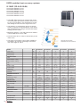
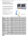
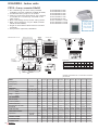
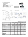
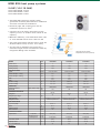
KX4 modular heat pump systems
8-16HP (22.4-45.0kW)
FDCA224HKXE4R 22.4kW
FDCA280HKXE4R 28.0kW
FDCA335HKXE4R 33.5kW
FDCA335HKXE4R-K 33.5kW
FDCA400HKXE4R 40.0kW
FDCA450HKXE4R 45.0kW
The KX4 VRF 2-pipe heat pump system
guarantees excellent performance for applications
that need to function only in the cooling mode,
or only in the heating mode, and it is therefore
ideal for open spaces.
50
Connects up to 26 indoor units/130% of the
capacity
40
Maximum efficiency, with COP values from 3.81
to 4.18 and EER from 3.35 to 3.93.
30
20
The length of the piping is the longest available
on the market: up to 510 m total length, and
with a max. pipe length of 160 m.
10
0
-10
Heating function with external
temperatures down to -20°C (wet bulb)
-20
MODEL
Power source
Cooling capacity
Heating capacity
ELECTRICAL DATA
Power
Power absorption - cooling
Power absorption - heating
EER
COP
Current - cooling
Current - heating
DIMENSIONS
External dimensions
Net weight
REFRIGERATION CIRCUIT
Refrigerant
Refrigerant pre-charge
Heat exchanger
Refrigerant control
AIR CONDITIONING
Type and quantity
Motor
Airflow and head
Max. noise level
PIPE SPECIFICATIONS
Pipe diameter
Connection method
Capacity control
N. of connectable I.U.
14
FDCA
HP
kW
kW
224 HKXE4R
280 HKXE4R
335 HKXE4R
400 HKXE4R
450 HKXE4R
8
10
12
14
16
22,40
28,00
33,50
40,00
45,00
25,00
31,50
37,50
45,00
50,00
Ph-V-Hz 3-380~415V-50HZ 3-380~415V-50HZ 3-380~415V-50HZ 3-380~415V-50HZ 3-380~415V-50HZ
kW
5,70
8,26
9,53
11,27
12,97
kW
5,98
8,06
9,84
11,73
13,10
height x width x depth
3,93
3,39
3,52
3,55
4,18
3,91
3,81
3,84
3,82
A
A
9,6~8,8
13,6~12,4
15,5~14,2
18,4~16,9
21,1~19,3
9,6~8,8
13,3~12,2
16,3~14,9
19,6~17,9
21,7~19,9
mm
Kg
1690x1350x720
1690x1350x720
1690x1350x720
1690x1350x720
1690x1350x720
240/245
240/245
245
290/310
290/310
R410A
R410A
R410A
R410A
R410A
Kg
14,2
Internally finned
and grooved tubes
Electronic expansion
valve
Axial fan x 2
W
Cool./Heat.
Liquid line
Discharge gas line
Suction gas line
m3/min (Pa)
14,2
Internally finned
and grooved tubes
Electronic expansion
valve
Axial fan x 2
3,47
14,2
17,0
17,0
Internally finned
and grooved tubes
Electronic expansion
valve
Internally finned
and grooved tubes
Electronic expansion
valve
Internally finned
and grooved tubes
Electronic expansion
valve
Axial fan x 2
Axial fan x 2
Axial fan x 2
120 x 2
120 x 2
386 x 2
386 x 2
386 x 2
220/180 (0, max 50) 220/180 (0, max 50) 280/260 (0, max 50) 250/220 (0, max 50) 260/240 (0, max 50)
dB(A)
57
58
60,5/61
58,5/59
61/61
mm (in)
mm (in)
mm (in)
ø9.52 (3/8)
ø9.52 (3/8)
ø12.70 (1/2)
ø12.70 (1/2)
ø12.70 (1/2)
-
-
ø19.05 (3/4)
ø22.22 (7/8)
ø25.4 (1)
ø25.4 (1)
ø28.58 (9/8)
Liquid side: flared fitting
Gas side: welded
%
27~16
13
Liquid side: flared fitting
Gas side: welded
Liquid side: flared fitting
Gas side: welded
Liquid side: flared fitting
Gas side: welded
Liquid side: flared fitting
Gas side: welded
20~114
19~117
15~114
13~112
16
20
23
26
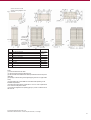
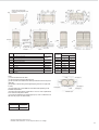
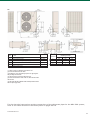
View from above of the unit after
connection including refrigeration circuit
connections
Anchor bolt positions for I
Lower
Anchor bolt positions for F J
Rear
Air intake
7-segment display
inspection port
Drain pipe
Right
Signal wire terminal
block
Left
Rif.
Terminal block
for power cable
connection
Gas side piping connection
B
Liquid side piping connection
C
Outlet for refrigerant piping
D
Opening for power cables
F
Hole for anchor bolts
G
Instruction plate
Right
Front
Item
A
For the refrigerant
piping, please refer
to the O.U.
specifications
Ø88
Ø50
M10, 4 holes
Drain pipe connection
Ø45, 3 holes
Dimensions
L1
Installation example
1
2
500
open
L2
10
10
L3
100
100
open
L4
10
H1
1500
-
not limited
not limited
H
Drain hole
Ø20, 6 holes
H2
K*
Oil equalising pipe connection
Ø3/8 (flare)
H3
1000
not limited
180x44.7
H4
not limited
-
L
Opening for handling
*14-16 HP models only
Notes
(1) Fix the unit with the anchor bolts.
(2) Leave at least 2m free space above the unit.
(3) The decal with the installation data shall be positioned under the front panel
(right side).
(4) Openings for electric wiring and refrigerant piping are knock out (open with
a cutter).
(5) For the piping inlet, use the Ø88 hole or the Ø100 hole depending on the
installation requirements.
(6) Use the fixing holes (M10x4) marked with "L" and "J" in case of replacement
of an outer unit of the previous series.
(7) Connect the refrigeration oil equalising pipe ("K") in case of combined use of
the outer unit (only for 14-16HP models).
When more units are installed
Dimensions
Installation example
A
B
500
open
L2
10
200
L3
100
300
L4
10
open
L5
0
400
L6
0
400
H1
1500
not limited
H2
not limited
not limited
H3
1000
not limited
H4
not limited
not limited
L1
Unit front side
Wall height H3
Intake
Wall height H3
Wall height H4
Wall height H2
rear
Front
Wall height H2
Service space
Intake
Wall height H4
Wall height H1
Installation space
All of the measurements shown are in mm.
Calculation of the noise levels: 1 m from front part of the unit; 1 m in height.
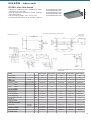
15
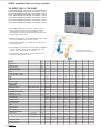
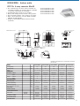
KX4 modular heat pump systems
18-24HP (50.4-68.0kW)
FDCA504HKXE4R
FDCA560HKXE4R
FDCA615HKXE4R
FDCA680HKXE4R
50.4kW
56.0kW
61.5kW
68.0kW
The KX4 VRF 2-pipe heat pump system
guarantees excellent performance for applications
that need to function only in the cooling mode,
or only in the heating mode, and it is therefore
ideal for open spaces.
Connects up to 40 indoor units/130% of the
capacity
Maximum efficiency, with COP values from 3.69
to 3.83 and EER from 2.72 to 3.42.
50
40
The length of the piping is the longest available
on the market: up to 510 m total length, and
with a max. pipe length of 160 m.
30
20
10
0
Heating function with external
temperatures down to -20°C (wet bulb)
-10
-20
MODEL
Power source
Cooling capacity
Heating capacity
ELECTRICAL DATA
Power
Power absorption - cooling
Power absorption - heating
EER
COP
Current - cooling
Current - heating
DIMENSIONS
External dimensions
Net weight
REFRIGERATION CIRCUIT
Refrigerant
Refrigerant pre-charge
Heat exchanger
Refrigerant control
AIR CONDITIONING
Type and quantity
Motor
Airflow and head
Max. noise level
PIPE SPECIFICATIONS
Pipe diameter
Connection method
Capacity control
N. of connectable I.U.
16
height x width x depth
FDCA
HP
kW
kW
504 HKXE4R
Ph-V-Hz
kW
kW
680 HKXE4R
18
20
22
24
50,40
56,00
61,50
68,00
56,50
63,00
69,00
73,00
3-380~415V-50HZ
3-380~415V-50HZ
3-380~415V-50HZ
3-380~415V-50HZ
14,73
17,21
20,37
24,98
15,15
17,07
18,48
19,08
3,42
3,25
3,02
2,72
3,69
3,73
3,83
A
A
24,1~22,0
28,2~25,8
33,1~30,3
40,3~36,9
25,2~23,1
28,5~26,1
30,7~28,1
31,6~29,0
mm
Kg
2048x1350x720
2048x1350x720
2048x1350x720
2048x1350x720
340
340
360
360
R410A
R410A
R410A
R410A
19,4
Internally finned
and grooved tubes
Electronic expansion
valve
Axial fan x 2
Liquid line
Discharge gas line
Suction gas line
615 HKXE4R
3,73
Kg
Cool./Heat.
560 HKXE4R
19,4
Internally finned
and grooved tubes
Electronic expansion
valve
26,2
Internally finned
and grooved tubes
Electronic expansion
valve
26,2
Internally finned
and grooved tubes
Electronic expansion
valve
Axial fan x 2
Axial fan x 2
W
386 x 2
386 x 2
386 x 2
386 x 2
m3/min (Pa)
270/250 (0, max 50)
270/250 (0, max 50)
270/250 (0, max 50)
270/250 (0, max 50)
dB(A)
60/60,5
60,5/62,5
63
63,5
mm (in)
mm (in)
mm (in)
ø12.70 (1/2)
ø12.70 (1/2)
ø12.70 (1/2)
ø12.70 (1/2)
-
-
-
-
ø28.58 (9/8)
ø28.58 (9/8)
ø28.58 (9/8)
ø28.58 (9/8)
Liquid side: flared fitting
Gas side: welded
%
Liquid side: flared fitting
Gas side: welded
Axial fan x 2
Liquid side: flared fitting
Gas side: welded
Liquid side: flared fitting
Gas side: welded
11~100
10~113
9~110
8~108
29
33
36
40
View from above of the unit after
connection including refrigeration circuit
connections
Anchor bolt positions for I
Lower
Anchor bolt positions for F J
Rear
Air intake
Drain pipe
7-segment display
inspection port
Front
Right
rear
Signal wire terminal
block
Left
Rif.
Terminal block
for power cable
connection
Front
Item
A
Gas side piping connection
B
Liquid side piping connection
C
Outlet for refrigerant piping
D
Opening for power cables
F
Hole for anchor bolts
G
Right
Instruction plate
Drain pipe connection
For the refrigerant
piping, please refer
to the O.U.
specifications
Ø100
Ø50
Dimensions
L1
Installation example
1
2
500
open
L2
10
10
L3
100
100
open
L4
10
Ø45.3, 3 holes
H1
1500
-
not limited
not limited
M10, 4 holes
H
Drain hole
Ø20.5, 3 holes
H2
K
Oil equalising pipe connection
Ø9.52 (flare)
H3
1000
not limited
Opening for handling
180x44.7
H4
not limited
-
L
Notes
(1) Fix the unit with the anchor bolts.
(2) Leave at least 2m free space above the unit.
(3) The decal with the installation data shall be positioned under the front panel
(right side).
(4) Openings for electric wiring and refrigerant piping are knock out (open with
a cutter).
(5) For the piping inlet, use the Ø88 hole or the Ø100 hole depending on the
installation requirements.
(6) Use the fixing holes (M10x4) marked with "L" and "J" in case of replacement
of an outer unit of the previous series.
(7) Connect the refrigeration oil equalising pipe ("K") in case of combined use of
the outer unit.
Wall height H3
Intake
Wall height H2
Service space
Intake
Wall height H4
Wall height H1
Installation space
All of the measurements shown are in mm.
Calculation of the noise levels: 1 m from front part of the unit; 1 m in height.
17
KX4 modular heat pump systems
26-32HP (73.5-90.0kW)
FDCA735HKXE4R
FDCA800HKXE4R
FDCA850HKXE4R
FDCA900HKXE4R
(FDCA335R+FDCA400R)
(FDCA400R+FDCA400R)
(FDCA400R+FDCA450R)
(FDCA450R+FDCA450R)
73.5kW
80.0kW
85.0kW
90.0kW
The KX4 VRF 2-pipe heat pump system
guarantees excellent performance for applications
that need to function only in the cooling mode,
or only in the heating mode, and it is therefore
ideal for open spaces.
Connects up to 48 indoor units/130% of the
capacity
Maximum efficiency, with COP values from 3.82
to 3.99 and EER from 3.47 to 3.64.
50
40
The length of the piping is the longest available
on the market: up to 510 m total length, and
with a max. pipe length of 160 m.
30
20
Double units can be connected up to a distance
of 10 m.
10
0
Heating function with external
temperatures down to -20°C (wet bulb)
-10
-20
MODEL
Power source
Cooling capacity
Heating capacity
ELECTRICAL DATA
Power
Power absorption - cooling
Power absorption - heating
EER
COP
Current - cooling
Current - heating
DIMENSIONS
External dimensions
Net weight
REFRIGERATION CIRCUIT
Refrigerant
Refrigerant pre-charge
Heat exchanger
Refrigerant control
AIR CONDITIONING
Type and quantity
Motor
Airflow and head
Max. noise level
PIPE SPECIFICATIONS
Pipe diameter
Connection method
Capacity control
N. of connectable I.U.
18
height x width x depth
FDCA
HP
kW
kW
735 HKXE4R
Ph-V-Hz
kW
kW
850 HKXE4R
900 HKXE4R
26
28
30
32
73,50
80,00
85,00
90,00
82,50
90,00
95,00
100,00
3-380~415V-50HZ
3-380~415V-50HZ
3-380~415V-50HZ
3-380~415V-50HZ
20,21
22,54
24,24
25,94
20,66
23,46
24,83
26,20
3,64
3,55
3,51
3,47
3,99
3,84
3,83
3,82
A
A
32,9~30,2
36,8~33,7
39,5~36,2
42,2~38,6
34,4~31,4
39,2~35,8
41,3~37,8
43,4~39,8
mm
Kg
(1690x1350x720) x 2
(1690x1350x720) x 2
(1690x1350x720) x 2
(1690x1350x720) x 2
310x2
310x2
310 x 2
310 x 2
R410A
R410A
R410A
R410A
Kg
34
Internally finned
and grooved tubes
Electronic expansion
valve
W
Liquid line
Discharge gas line
Suction gas line
800 HKXE4R
34
Internally finned
and grooved tubes
Electronic expansion
valve
34
Internally finned
and grooved tubes
Electronic expansion
valve
34
Internally finned
and grooved tubes
Electronic expansion
valve
Axial fan x 4
Axial fan x 4
Axial fan x 4
386 x 4
386 x 4
386 x 4
Axial fan x 4
386 x 4
260 x 2 (0, max 50)
m3/min (Pa)
220+250 (0, max 50)
250 x 2 (0, max 50)
250+260 (0, max 50)
dB(A)
60,5/61
61,5/62
63
64
mm (in)
mm (in)
mm (in)
ø12.70 (1/2)
ø12.70 (1/2)
ø12.70 (1/2)
ø12.70 (1/2)
-
-
-
-
ø28.58 (9/8)
ø28.58 (9/8)
ø28.58 (9/8)
ø28.58 (9/8)
Liquid side: flared fitting
Gas side: welded
%
8~123
43
Liquid side: flared fitting
Gas side: welded
Liquid side: flared fitting
Gas side: welded
Liquid side: flared fitting
Gas side: welded
4~114
4~112
4~112
47
48
48
View from above of the unit after
connection including refrigeration circuit
connections
Anchor bolt positions for I
Lower
Anchor bolt positions for F J
Rear
Air intake
7-segment display
inspection port
Drain pipe
Right
Signal wire terminal
block
Left
Rif.
Terminal block
for power cable
connection
rear
Front
Instruction plate
Right
Front
Item
A
Gas side piping connection
B
Liquid side piping connection
C
Outlet for refrigerant piping
D
Opening for power cables
F
Hole for anchor bolts
M10, 4 holes
G
Drain pipe connection
Ø45, 3 holes
H
Drain hole
Ø20, 6 holes
K
Oil equalising pipe connection
Ø3/8 (flare)
L
Opening for handling
180x44.7
For the refrigerant
piping, please refer
to the O.U.
specifications
Ø88
Ø50
Notes
(1) Fix the unit with the anchor bolts.
(2) Leave at least 2m free space above the unit.
(3) The decal with the installation data shall be positioned under the front panel
(right side).
(4) Openings for electric wiring and refrigerant piping are knock out (open with
a cutter).
(5) For the piping inlet, use the Ø88 hole or the Ø100 hole depending on the
installation requirements.
(6) Use the fixing holes (M10x4) marked with "L" and "J" in case of replacement
of an outer unit of the previous series.
(7) Connect the refrigeration oil equalising pipe ("K") in case of combined use of
the outer unit.
All of the measurements shown are in mm.
Calculation of the noise levels: 1 m from front part of the unit; 1 m in height.
19
KX4 modular heat pump systems
34-48HP (96.0-136.0kW)
FDCA960HKXE4R (FDCA450R+FDCA504R) 96.0kW
FDCA1010HKXE4R (FDCA504R+FDCA504R) 101.0kW
FDCA1065HKXE4R (FDCA504R+FDCA560R) 106.5kW
FDCA1130HKXE4R (FDCA560R+FDCA560R) 113.0kW
FDCA1180HKXE4R (FDCA560R+FDCA615R) 118.0kW
FDCA1235HKXE4R (FDCA615R+FDCA615R) 123.5kW
FDCA1300HKXE4R (FDCA615R+FDCA680R) 130.0kW
FDCA1360HKXE4R (FDCA680R+FDCA680R) 136.0kW
The KX4 VRF 2-pipe heat pump system
guarantees excellent performance for applications
that need to function only in the cooling mode,
or only in the heating mode, and it is therefore
ideal for open spaces.
Connects up to 48 indoor units/130% of the
capacity
50
40
Maximum efficiency, with COP values from 3.71
to 3.83 and EER from 2.72 to 3.47.
30
20
The length of the piping is the longest available
on the market: up to 510 m total length, and
with a max. pipe length of 160 m.
10
0
Double units can be connected up to a distance
of 10 m.
Heating function with external
temperatures down to -20°C (wet bulb)
-10
-20
MODEL
Power source
Cooling capacity
Heating capacity
ELECTRICAL DATA
Power
Power absorption - cooling
Power absorption - heating
EER
COP
Current - cooling
Current - heating
DIMENSIONS
External dimensions
Net weight
REFRIGERATION CIRCUIT
Refrigerant
Refrigerant pre-charge
Heat exchanger
Refrigerant control
AIR CONDITIONING
Type and quantity
Motor
Airflow and head
Max. noise level
PIPE SPECIFICATIONS
Pipe diameter
Connection method
Capacity control
N. of connectable I.U.
20
FDCA
HP
kW
kW
960HKXE4R
1010HKXE4R
1065HKXE4R
1130HKXE4R
1180HKXE4R
1235HKXE4R
1300HKXE4R
34
36
38
40
42
44
46
1360HKXE4R
48
96,00
101,00
106,50
113,00
118,00
123,5
130,00
136,00
108,00
113,00
119,50
127,00
132,00
138,00
142,00
146,00
Ph-V-Hz 3-380~415V-50HZ 3-380~415V-50HZ 3-380~415V-50HZ 3-380~415V-50HZ 3-380~415V-50HZ 3-380~415V-50HZ 3-380~415V-50HZ 3-380~415V-50HZ
kW
27,70
29,46
31,94
34,42
37,58
40,74
45,35
49,96
kW
28,25
30,30
32,22
34,14
35,55
36,96
37,56
38,16
A
A
height x width x depth
mm
Kg
Kg
3,47
3,43
3,33
3,28
3,14
3,03
2,87
3,82
3,73
3,71
3,72
3,71
3,73
3,78
2,72
3,83
45,2~41,3
48,2~44,0
52,3~47,8
56,4~51,6
61,3~56,1
66,2~60,6
73,4~67,2
80,6~73,8
46,9~43,0
50,4~46,2
53,7~49,2
57,0~52,2
59,2~54,2
61,4~56,2
62,3~57,1
63,2~58,2
(1690x1350x720)x1
(2048x1350x720)x1(2048x1350x720)x2(2048x1350x720)x2(2048x1350x720)x2 2048x1350x720x2 2048x1350x720x2 (2048x1350x720)x2(2048x1350x720)x2
315 + 340
340 x 2
340 x 2
340 x 2
340 + 360
360 x 2
360 x 2
360 x 2
R410A
R410A
R410A
R410A
R410A
R410A
R410A
R410A
36,4
38,8
38,8
38,8
45,6
52,4
52,4
52,4
Internally finned
Internally finned
Internally finned
Internally finned
Internally finned
Internally finned
Internally finned
Internally finned
and grooved tubes and grooved tubes and grooved tubes and grooved tubes and grooved tubes and grooved tubes and grooved tubes and grooved tubes
Electronic expansion Electronic expansion Electronic expansionElectronic expansion Electronic expansion Electronic expansion Electronic expansion Electronic expansion
valve
valve
valve
valve
valve
valve
valve
valve
W
Axial fan x 4
Axial fan x 4
Axial fan x 4
Axial fan x 4
Axial fan x 4
Axial fan x 4
Axial fan x 4
Axial fan x 4
386 x 4
386 x 4
386 x 4
386 x 4
386 x 4
386 x 4
386 x 4
386 x 4
m3/min (Pa) 260+270 (0, max 50) 270x2 (0, max 50) 270x2 (0, max 50) 270x2 (0, max 50) 270x2 (0, max 50) 270x2 (0, max 50) 270x2 (0, max 50) 270x2 (0, max 50)
dB(A)
Liquid line
Discharge gas line
Suction gas line
mm (in)
mm (in)
mm (in)
63,5/64
63/63,5
63/65
63,5/65,5
65/66
66/66
66,5
66,5
ø12.70 (1/2)
ø12.70 (1/2)
ø12.70 (1/2)
ø12.70 (1/2)
ø12.70 (1/2)
ø12.70 (1/2)
ø12.70 (1/2)
ø12.70 (1/2)
-
-
-
-
-
-
-
-
ø28.58 (9/8)
ø28.58 (9/8)
ø28.58 (9/8)
ø28.58 (9/8)
ø28.58 (9/8)
ø28.58 (9/8)
ø28.58 (9/8)
ø28.58 (9/8)
Liquid side: flared fittingLiquid side: flared fitting Liquid side: flared fittingLiquid side: flared fittingLiquid side: flared fittingLiquid side: flared fittingLiquid side: flared fittingLiquid side: flared fitting
Gas side: welded
Gas side: welded
Gas side: welded
Gas side: welded
Gas side: welded
Gas side: welded
Gas side: welded
Gas side: welded
%
4~110
48
4~109
4~111
4~112
4~112
4~109
4~108
4~107
48
48
48
48
48
48
48
View from above of the unit after
connection including refrigeration circuit
connections
Anchor bolt positions for I
Lower
Anchor bolt positions for F J
Rear
Air intake
7-segment display
inspection port
Drain pipe
Signal wire terminal
block
Left
Rif.
Terminal block
for power cable
connection
Front
Right
rear
Right
Instruction plate
Front
Item
For the refrigerant
piping, please refer
to the O.U.
specifications
A
Gas side piping connection
B
Liquid side piping connection
C
Outlet for refrigerant piping
D
Opening for power cables
Ø50
F
Hole for anchor bolts
M10, 4 holes
G
Drain pipe connection
Ø45.3, 3 holes
H
Drain hole
Ø20.5, 3 holes
K
Oil equalising pipe connection
Ø9.52 (flare)
L
Opening for handling
180x44.7
Ø100
Notes
(1) Fix the unit with the anchor bolts.
(2) Leave at least 2m free space above the unit.
(3) The decal with the installation data shall be positioned under the front panel
(right side).
(4) Openings for electric wiring and refrigerant piping are knock out (open with a
cutter).
(5) For the piping inlet, use the Ø88 hole or the Ø100 hole depending on the
installation requirements.
(6) Use the fixing holes (M10x4) marked with "L" and "J" in case of replacement
of an outer unit of the previous series.
(7) Connect the refrigeration oil equalising pipe ("K") in case of combined use of
the outer unit.
All of the measurements shown are in mm.
Calculation of the noise levels: 1 m from front part of the unit; 1 m in height.
21
KX4
Refrigerant piping
The KX4 system is manufactured in accordance with the highest standards of quality and reliability and therefore
it is essential that the methods of installation and materials used have the same qualitative characteristics, to
guarantee long-term trouble-free operation.
We recommend using copper refrigerant pipes, which must be chosen allowing for the greater operating pressure
of the R410A refrigerant gas.
The materials used must respect European standard EN12735 and the RoHS directive, which envisages the
prohibition (in other words limiting the use) of lead, mercury, cadmium, hexavalent chrome and some fire
retardants in electric and electronic equipment (polybrominated biphenyls (PBBs) and polybrominated diphenyl
ethers (PBDEs) to very low values. The connections to the indoor units and those between the outdoor units
must be made using the original Mitsubishi Heavy Industries branch kits and header kits.
The additional R410A refrigerant gas must be charged using electronic scales. The additional quantity of gas
must be calculated in accordance with the data supplied by the manufacturer, established on the basis of the
length and diameter of each section of the refrigerant pipes in the system.
Pipe fitting
Single outdoor unit
Liquid side
Gas side
System of refrigerant pipes that uses the header kit
Combined outdoor units
System of refrigerant pipes that uses the branch kit
Condensate pipe
Pipe fitting
Pipe fitting
Refrigerant oil
equalising pipe
System of refrigerant pipes that uses
the branch kit
Refrigerant oil
equalising pipe
DOS-2A-1
DOS-2A-1
Outdoor units (HP)
Liquid side
8
Main piping
=<90 m
Gas side
Liquid side
System of refrigerant pipes that uses the
header kit
10
14
16
18
20
22
24
26
28
30
32
34
36
38
40
42
44
48
3/8" 3/8" 1/2" 1/2" 1/2"
1/2"
1/2"
1/2"
1/2"
5/8"
5/8"
5/8"
5/8"
5/8"
5/8"
3/4"
3/4"
3/4" 3/4"
3/4"
3/4" 7/8"
Main piping
=<90 m
12
1"
1" 1.1/8" 1.1/8" 1.1/8" 1.1/8" 1.1/8" 1.3/8" 1.3/8" 1.3/8" 1.3/8" 1.3/8" 1.3/8" 1.3/8" 1.3/8" 1.3/8" 1.3/8" 1.3/8"
1/2" 1/2" 1/2" 1/2" 1/2"
Gas side
5/8"
5/8"
5/8"
5/8"
3/4"
3/4"
3/4"
3/4"
3/4"
3/4"
7/8"
7/8"
7/8" 7/8"
7/8"
7/8" 7/8" 7/8" 1.1/8" 1.1/8" 1.1/8" 1.1/8" 1.1/8" 1.1/8" 1.3/8" 1.3/8" 1.3/8" 1.3/8" 1.3/8" 1.3/8" 1.3/8" 1.3/8" 1.3/8" 1.3/8" 1.3/8"
yes
Horizontally
Headers
Branches
Floor
no
Floor
Vertically
no
Floor
22
yes
Floor
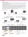
Electrical connections
Connecting the power cables
Power (outdoor unit side)
Three-phase 380/415V 50Hz
The new KX4 system has very simple electrical
connections with the indoor unit, thanks to a
control circuit with 2 non-polarized wires. The
power wiring can be passed through the prepunched holes in the front, right, left or rear of
the outdoor unit. A separate power line must
be installed for outdoor units and 3-phase outdoor
units. The interaction between outdoor and
indoor unit is also done through the control
device.
Ground fault
circuit breaker
Magnetothermal
switch
Connecting the signal wire
Power (outdoor unit side)
Three-phase 380/415V 50Hz
Outdoor unit 1
Ground fault
circuit breaker
Outdoor unit 2
Ground fault
circuit breaker
Magnetothermal
switch
Magnetothermal
switch
Earth
Earth
Signal wire between outdoor unit and indoor unit
Signal wire between indoor units
Indoor unit
Wiring the wired
controller
Wired controller
Power source
(indoor unit side) singlephase 220/240V 50Hz
Example with an outdoor unit
The signal wire is 5V DC, so it must never be
connected to a 220/240V power line as the
electronic boards in all of the units connected
to the signal wire would be irreparably damaged.
The signal line has 2 non-polarized wires,
therefore it is not strictly necessary to respect
the same order (A, B) of the wires and contacts
on the terminal board on the different outdoor
and indoor units. Use shielded cables for the
signal wire. Connect the shield to a metallic part
of the unit near the terminal board A or B. Avoid,
as far as possible, installing the cable of the
signal wire with the power cable.
The signal wires of the indoor and outdoor units are
non-polarized. All the connections shown can be made
Outdoor unit
signals terminal
board
2 wires (0.75-2mm2)
Length of signal wire:
max. 1000 m or less
When connecting to the terminal
boards use M3.5 ring terminals
Indoor unit signals
terminal board
7 mm or smaller
Example with several outdoor units
O.U.
O.U
O.U.
O.U.
2 wires (0.75-2mm2)
Length of signal wire: max. 1000 m or less
I.U.
I.U.
I.U.
I.U.
(a) A maximum of 48 indoor units can be connected to a signal wire and it is possible to create groups of indoor
units connected to the same outdoor unit or distinct outdoor units, as long as these are connected to the same
signal wire.
(b) The signal wire can also be connected as described below.
O.U.
O.U.
O.U.
O.U.
It cannot be created a loop on the signal wire
O.U.
I.U.
I.U.
I.U.
O.U.
O.U.
Here its showed an
example of wrong
signal wire
connection, this line
forms a loop.
I.U.
I.U.
I.U.
O.U.
I.U.
I.U.
I.U.
I.U.
Specifications relevant to the connection of the wired controller
The standard specifications for wiring the wired controller are 0.3 mm2
x 3 wires. The maximum length allowed is 600 m. If the length is over
100 m, refer to the table.
If the wiring of the wired controller runs parallel with a power line, or
is exposed to electromagnetic disturbance (high frequency equipment),
use shielded wires, connecting just one end of the shield to earth.
Length (m)
Type of wires
100-200
0.5 mm2 x 3 wires
up to 300
0.75 mm2 x 3 wires
up to 400
1.25 mm2 x 3 wires
up to 600
2.0 mm2 x 3 wires
23
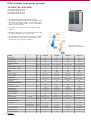
KXR4
KXR4 modular heat recovery systems
Heat recovery unit
The KXR4 heat recovery system offers
simultaneous cooling and heating modes for
the single indoor unit to meet the needs and
characteristics of the environments to
condition.
Thanks to highly sophisticated control systems
it is possible to condition several indoor
environments, with different cooling or heating
requirements, such as in the case of buildings
exposed on 4 sides, where the heat gain/loss
varies notably in the different zones.
The range starts with a 8 HP (22.4 kW) model,
and goes up to a model with the maximum
capacity for a single outdoor unit available
on the market (24 HP), with a cooling capacity
of 68 kW. The outdoor units can also be
combined proving up to 48 HP/136 kW on a
single system.
DIS-22-1-R
DIS-180-1-R
DIS-371-1-R
DIS-540-1-R
Branch piping set (opt.)
DIS-22-1
DIS-180-1
DIS-371-1
16HP
Total capacity of the I.U. upstream of the PFD
<18 kW
>18 kW - <37,1 kW
>37,1 kW - <54 kW
>54 kW
Total capacity of the I.U. downstream of PFD
<18 kW
>18 kW - <37,1 kW
>37,1 kW - <54 kW
DIS-540-1
>54 kW
PFD112-ER
<11.2 kW
PFD180-ER
<18.0 kW
1-8
PFD280-ER
<28.0 kW
1-10
Flow branch controller
N. of connectable units
1-5
<37.1 kW
PFD112X4-ER
Outdoor unit branch piping set*
DOS-2A-1-R
10HP
FDCA280HKXRE4BR*
12HP
18HP
14HP
FDCA335HKXRE4BR*
FDCA335HKXRE4BRK
20HP
FDCA400HKXRE4BR
24HP
22HP
FDCA450HKXRE4BR FDCA504HKXRE4BR FDCA560HKXRE4BR FDCA615HKXRE4BR FDCA680HKXRE4BR
Combinations of units with heat recovery
Branch piping set (opt.)
8HP
FDCA224HKXRE4BR*
max. 16
26HP
FDCA735HKXRE4BR
(FDCA335HKXRE4BRK+FDCA400HKXRE4BR)
30HP
28HP
FDCA800HKXRE4BR
FDCA850HKXRE4BR
(FDCA400HKXRE4BR+FDCA400HKXRE4BR) (FDCA400HKXRE4BR+FDCA450HKXRE4BR)
36HP
32HP
34HP
38HP
40HP
42HP
44HP
46HP
48HP
FDCA900HKXRE4BR
FDCA960HKXRE4BR
(FDCA450HKXRE4BR+FDCA450HKXRE4BR) (FDCA450HKXRE4BR+FDCA504HKXRE4BR)
FDCA1010HKXRE4BR
(FDCA504HKXRE4R+FDCA504HKXRE4BR)
FDCA1065HKXRE4BR
FDCA1130HKXRE4BR
FDCA1180HKXRE4BR
(FDCA504HKXRE4BR+FDCA560HKXRE4BR) (FDCA560HKXRE4BR+FDCA560HKXRE4BR) (FDCA560HKXRE4BR+FDCA615HKXRE4BR)
FDCA1300HKXRE4BR
FDCA1360HKXRE4BR
FDCA1235HKXRE4BR
(FDCA615HKXRE4BR+FDCA615HKXRE4BR) (FDCA615HKXRE4BR+FDCA680HKXRE4BR) (FDCA680HKXRE4BR+FDCA680HKXRE4BR)
* These models of outdoor units are not modular, therefore they
can only be used in stand-alone mode. For the 26HP combination
(14HP+12HP), the outdoor unit FDCA335HKXRE4R-K must
be used.
for 2 units (from 735 to 1360)
* To use only with 2 combined outdoor units and not for a
stand-alone installation.
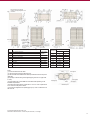
Number of indoor units available for combinations
Up to 48 indoor units, of 12 different types and capacities, for a total of roughly 61 models can be connected
to the higher capacity outdoor unit.
HP equivalent
Model
N. of connectable units
HP equivalent
Model
N. of connectable units
24
8
10
12
14
16
18
20
22
24
26
28
FDCA224HKXRE4BR FDCA280HKXRE4BR FDCA335HKXRE4BR FDCA400HKXRE4BR FDCA450HKXRE4BR FDCA504HKXRE4BR FDCA560HKXRE4BR FDCA615HKXRE4BR FDCA680HKXRE4BR FDCA735HKXRE4BR FDCA800HKXRE4BR
FDCA335HKXRE4BRK
1-13
30
1-16
32
1-20
1-23
34
1-26
36
1-29
38
1-33
40
2-36
42
2-40
44
2-43
46
2-47
48
FDCA850HKXRE4BR FDCA900HKXRE4BR FDCA960HKXRE4BR FDCA1010HKXRE4BR FDCA1065HKXRE4BR FDCA1130HKXRE4BR FDCA1180HKXRE4BR FDCA1235HKXRE4BR FDCA1300HKXRE4BR FDCA1360HKXRE4BR
2-48
2-48
2-48
2-48
2-48
3-48
3-48
3-48
3-48
3-48
The refrigerant connections of the KXR4 heat recovery
system follow one route, with two pipes connected
to the PFD flow divider and the third connected
directly to each indoor unit off the main refrigerant
line. This reduces the number of welds to execute in
situ and, therefore also the time required for installation.
The PFD flow divider is available for single connections
or 4-way connections, where each unit connected
operates independently in the cooling or heating mode.
The main advantages of the KXR4 system:
free choice between cooling and heating mode for
each indoor unit;
high efficiency and excellent energy savings;
use of the same indoor unit as the KX4 with flow
divider;
power rating of the outdoor units from 8HP to 48HP;
up to 48 indoor units can be connected to the same
refrigerant system
The advantages of simultaneous heating/cooling:
in buildings with a low thermal inertia, especially in
those built using materials such as glass and metal,
the factor of exposure to direct solar radiation often
makes a great difference to the air conditioning
requirements (especially in spring and autumn);
in buildings with variable environment, where there
are crowded areas (meeting rooms, restaurants,
etc.) or where cooling is also required in winter
(Data Processing Centres, servers etc.), a complete
freedom of choice is required for the operating mode.
Outdoor unit
High-pressure gas
Low-pressure gas
PFD
Compressor
Accumulator
Indoor unit Indoor unit Indoor unit Indoor unit
Receiver
System characterised by simultaneous cooling and heating functions.
25
KXR4 modular heat recovery systems
8-16HP (22.4-45.0kW)
FDCA224HKXRE4BR 22.4kW
FDCA280HKXRE4BR 28.0kW
FDCA335HKXRE4BR 33.5kW
FDCA335HKXRE4BRK 33.5kW
FDCA400HKXRE4BR 40.0kW
FDCA450HKXRE4BR 45.0kW
The KXR4 VRF heat recovery system with 3 inter
connecting pipes guarantees excellent performance
for any type of building, with simultaneous cooling
and heating functions for each single indoor unit.
The efficiency is maximized by the use of the DC
Inverter compressor and the distribution of the surplus
heat generated during cooling to the areas that require
heating, and vice versa.
50
40
Maximum efficiency, with COP values from 3.68 to
4,24 and EER from 3.28 to 3.80.
30
20
Connects from 50% to 130% of the capacity of the
indoor units.
10
The length of the piping is the longest available on
the market: up to 510 m total length, and with a
max. pipe length of 160 m.
0
Heating function with external
temperatures down to -20°C (wet bulb)
-10
-20
MODEL
Power source
Cooling capacity
Heating capacity
ELECTRICAL DATA
Power
Power absorption - cooling
Power absorption - heating
EER
COP
Current - cooling
Current - heating
DIMENSIONS
External dimensions
Net weight
REFRIGERATION CIRCUIT
Refrigerant
Refrigerant pre-charge
Heat exchanger
Refrigerant control
AIR CONDITIONING
Type and quantity
Motor
Airflow and head
Max. noise level
PIPE SPECIFICATIONS
Pipe diameter
Connection method
Capacity control
N. of connectable I.U.
26
FDCA
HP
kW
kW
224 HKXRE4BR
280 HKXRE4BR
335 HKXRE4BR
400 HKXRE4BR
450 HKXRE4BR
8
10
12
14
16
22,40
28,00
33,50
40,00
45,00
25,00
31,50
37,50
45,00
50,00
Ph-V-Hz 3-380~415V-50HZ 3-380~415V-50HZ 3-380~415V-50HZ 3-380~415V-50HZ 3-380~415V-50HZ
kW
10,17
5,90
8,54
13,57
11,61
kW
9,55
5,90
8,55
13,55
12,18
height x width x depth
3,80
3,28
3,29
3,45
4,24
3,68
3,93
3,69
3,69
A
A
9,1~8,3
13,6~12,4
16,5~15,1
19,0~17,4
21,6~19,8
9,2~8,4
13,5~12,4
15,5~14,2
20,3~18,6
22,4~20,5
mm
Kg
1690x1350x720
1690x1350x720
1690x1350x720
1690x1350x720
1690x1350x720
250
250
250
315
315
R410A
R410A
R410A
R410A
R410A
Kg
W
14,2
14,2
14,2
Internally finned
and grooved tubes
Electronic expansion
valve
Internally finned
and grooved tubes
Electronic expansion
valve
Internally finned
and grooved tubes
Electronic expansion
valve
17,0
Internally finned
and grooved tubes
Electronic expansion
valve
Axial fan x 2
Axial fan x 2
Axial fan x 2
Axial fan x 2
126 x 2
126 x 2
386 x 2
386 x 2
3,32
17,0
Internally finned
and grooved tubes
Electronic expansion
valve
Axial fan x 2
386 x 2
220/180(0, max 50) 220/180(0, max 50) 280/260(0, max 50) 250/220(0, max 50) 260/240(0, max 50)
59,5/60
60,5/62,5
62,5/62,5
57/57
57/59
dB(A)
Cool./Heat.
m3/min (Pa)
Liquid line
Discharge gas line
Suction gas line
mm (in)
mm (in)
mm (in)
ø9.52 (3/8)
ø9.52 (3/8)
ø12.70 (1/2)
ø12.70 (1/2)
ø12.70 (1/2)
ø15.88 (5/8)
ø19.05 (3/4)
ø19.05 (3/4)
ø22.22 (7/8)
ø22.22 (7/8)
ø19.05 (3/4)
ø22.22 (7/8)
ø22.22 (7/8)
ø28.58 (9/8)
Liquid side: flared fitting
Gas side: welded
Liquid side: flared fitting
Gas side: welded
Liquid side: flared fitting
Gas side: welded
%
Liquid side: flared fitting
Gas side: welded
ø28.58 (9/8)
Liquid side: flared fitting
Gas side: welded
24~114
19~109
18~103
14~113
13~109
13
16
20
23
26
View from above of the unit after
connection including refrigeration circuit
connections
Anchor bolt positions for I
Lower
Anchor bolt positions for F J
Rear
Air intake
Drain pipe
7-segment display
inspection port
Right
Signal wire terminal
block
Terminal block
for power cable
connection
Left
Rif.
Instruction plate
Right
Front
Item
For the refrigerant
piping, please refer
to the O.U.
specifications
A
Gas side piping connection
B
Liquid side piping connection
C
Outlet for refrigerant piping
D
Opening for power cables
Ø50
F
Hole for anchor bolts
M10, 4 holes
G
Drain pipe connection
rear
Front
Ø100
Dimensions
L1
Installation example
1
2
500
open
L2
10
10
L3
100
100
open
L4
10
Ø45, 3 holes
H1
1500
-
not limited
not limited
H
Drain hole
Ø20, 6 holes
H2
K*
Oil equalising pipe connection
Ø3/8" (flare)
H3
1000
not limited
180x44.7
H4
not limited
-
L
Opening for handling
*14-16 HP models only
Notes
(1) Fix the unit with the anchor bolts.
(2) Leave at least 2m free space above the unit.
(3) The decal with the installation data shall be positioned under the front panel
(right side).
(4) Openings for electric wiring and refrigerant piping are knock out (open with
a cutter).
(5) For the piping inlet, use the Ø88 hole or the Ø100 hole depending on the
installation requirements.
(6) Use the fixing holes (M10x4) marked with "L" and "J" in case of replacement
of an outer unit of the previous series.
(7) Connect the refrigeration oil equalising pipe ("K") in case of combined use of
the outer unit (only for 14-16HP models).
Wall height H3
Intake
Wall height H2
Service space
Intake
Wall height H4
Wall height H1
Installation space
O.U. branch piping set
Outdoor unit
Branch piping set
for 2 units (735-900)
DOS-2A-1
All of the measurements shown are in mm.
Calculation of the noise levels: 1 m from front part of the unit; 1 m in height.
27
KXR4 modular heat recovery systems
18-24HP (50.4-68.0kW)
FDCA504HKXRE4BR 50.4kW
FDCA560HKXRE4BR 56.0kW
FDCA615HKXRE4BR 61.5kW
FDCA680HKXRE4BR 68.0kW
The KXR4 VRF heat recovery system with 3
inter-connecting pipes guarantees excellent
performance for any type of building, with
simultaneous cooling and heating functions for
each single indoor unit.
The efficiency is maximized by the use of the
DC Inverter compressor and the distribution of
the surplus heat generated during cooling to the
areas that require heating, and vice versa.
50
Maximum efficiency, with COP values from 3.56
to 3.71 and EER from 2.62 to 3.21.
40
30
Connects from 50% to 130% of the capacity of
the indoor units.
20
10
The length of the piping is the longest available
on the market: up to 510 m total length, and
with a max. pipe length of 160 m.
0
Heating function with external
temperatures down to -20°C (wet bulb)
-10
-20
MODEL
Power source
Cooling capacity
Heating capacity
ELECTRICAL DATA
Power
Power absorption - cooling
Power absorption - heating
EER
COP
Current - cooling
Current - heating
DIMENSIONS
External dimensions
Net weight
REFRIGERATION CIRCUIT
Refrigerant
Refrigerant pre-charge
Heat exchanger
Refrigerant control
AIR CONDITIONING
Type and quantity
Motor
Airflow and head
Max. noise level
PIPE SPECIFICATIONS
Pipe diameter
Connection method
Capacity control
N. of connectable I.U.
28
height x width x depth
FDCA
HP
kW
kW
504 HKXRE4BR
Ph-V-Hz
kW
kW
680 HKXRE4BR
18
20
22
24
56,00
61,50
68,00
56,50
63,00
69,00
73,00
3-380~415V-50HZ
3-380~415V-50HZ
3-380~415V-50HZ
3-380~415V-50HZ
15,69
18,76
21,47
25,99
15,62
17,69
19,11
19,69
3,21
2,99
2,86
2,62
3,62
3,56
3,61
3,71
A
A
24,6~22,5
29,7~27,2
34,7~31,8
44,9~41,1
26,1~23,9
29,5~27,0
31,6~28,9
34,0~31,1
mm
Kg
2048x1350x720
2048x1350x720
2048x1350x720
2048x1350x720
345
345
365
365
R410A
R410A
R410A
R410A
19,4
Internally finned
and grooved tubes
Electronic expansion
valve
Liquid line
Discharge gas line
Suction gas line
615 HKXRE4BR
50,40
Kg
Cool./Heat.
560 HKXRE4BR
19,4
26,2
Internally finned
and grooved tubes
Electronic expansion
valve
Internally finned
and grooved tubes
Electronic expansion
valve
26,2
Internally finned
and grooved tubes
Electronic expansion
valve
Axial fan x 2
Axial fan x 2
Axial fan x 2
W
386 x 2
386 x 2
386 x 2
386 x 2
m3/min (Pa)
270/250 (0, max 50)
270/250 (0, max 50)
270/250 (0, max 50)
270/250 (0, max 50)
dB(A)
61/61,5
62/62,5
64/64
64,5/64,5
mm (in)
mm (in)
mm (in)
ø12.70 (1/2)
ø12.70 (1/2)
ø12.70 (1/2)
ø12.70 (1/2)
ø22.22 (7/8)
ø22.22 (7/8)
ø25.40 (1)
ø25.40 (1)
ø28.58 (9/8)
ø28.58 (9/8)
ø28.58 (9/8)
ø28.58 (9/8)
Liquid side: flared fitting
Gas side: welded
%
Liquid side: flared fitting
Gas side: welded
Liquid side: flared fitting
Gas side: welded
Axial fan x 2
Liquid side: flared fitting
Gas side: welded
11~107
9~107
8~110
8~100
29
33
36
40
View from above of the unit after
connection including refrigeration circuit
connections
Anchor bolt positions for I
Anchor bolt positions for F J
Rear
Lower
Air intake
7-segment display
inspection port
Drain pipe
Front
Signal wire terminal
block
Left
Rif.
Terminal block
for power cable
connection
Gas side piping connection
B
Liquid side piping connection
C
Outlet for refrigerant piping
D
Opening for power cables
F
Hole for anchor bolts
G
Drain pipe connection
rear
Right
Instruction plate
Front
Item
A
Right
For the refrigerant
piping, please refer
to the O.U.
specifications
Ø100
Ø50
Dimensions
L1
Installation example
1
2
500
open
L2
10
10
L3
100
100
open
L4
10
Ø45.3, 3 holes
H1
1500
-
not limited
not limited
M10, 4 holes
H
Drain hole
Ø20.5, 3 holes
H2
K
Oil equalising pipe connection
Ø9.52 (flare)
H3
1000
not limited
Opening for handling
180x44.7
H4
not limited
-
L
Notes
(1) Fix the unit with the anchor bolts.
(2) Leave at least 2m free space above the unit.
(3) The decal with the installation data shall be positioned under the front panel
(right side).
(4) Openings for electric wiring and refrigerant piping are knock out (open with
a cutter).
(5) For the piping inlet, use the Ø88 hole or the Ø100 hole depending on the
installation requirements.
(6) Use the fixing holes (M10x4) marked with "L" and "J" in case of replacement
of an outer unit of the previous series.
(7) Connect the refrigeration oil equalising pipe ("K") in case of combined use of
the outer unit.
Wall height H3
Intake
Wall height H2
Service space
Intake
Wall height H4
Wall height H1
Installation space
All of the measurements shown are in mm.
Calculation of the noise levels: 1 m from front part of the unit; 1 m in height.
29
KXR4 modular heat recovery systems
26-32HP (73.5-90.0kW)
FDCA735HKXRE4BR (FDCA335R+FDCA400R) 73.5kW
FDCA800HKXRE4BR (FDCA400R+FDCA400R) 80.0kW
FDCA850HKXRE4BR (FDCA400R+FDCA450R) 85.0kW
FDCA900HKXRE4BR (FDCA450R+FDCA450R) 90.0kW
The KXR4 VRF heat recovery system with 3 inter
connecting pipes guarantees excellent performance
for any type of building, with simultaneous cooling
and heating functions for each single indoor unit.
The efficiency is maximized by the use of the DC
Inverter compressor and the distribution of the
surplus heat generated during cooling to the areas
that require heating, and vice versa.
50
Maximum efficiency, with COP values from 3.69
to 3.83 and EER from 3.32 to 3.49.
40
Connects from 50% to 130% of the capacity of
the indoor units.
30
20
The length of the piping is the longest available
on the market: up to 510 m total length, and with
a max. pipe length of 160 m.
10
0
The modular units can be connected up to a
maximum distance of 10 m.
Heating function with external
temperatures down to -20°C (wet bulb)
-10
-20
MODEL
Power source
Cooling capacity
Heating capacity
ELECTRICAL DATA
Power
Power absorption - cooling
Power absorption - heating
EER
COP
Current - cooling
Current - heating
DIMENSIONS
External dimensions
Net weight
REFRIGERATION CIRCUIT
Refrigerant
Refrigerant pre-charge
Heat exchanger
Refrigerant control
AIR CONDITIONING
Type and quantity
Motor
Airflow and head
Max. noise level
PIPE SPECIFICATIONS
Pipe diameter
Connection method
Capacity control
N. of connectable I.U.
30
height x width x depth
FDCA
HP
kW
kW
735 HKXRE4BR
Ph-V-Hz
kW
kW
850 HKXRE4BR
900 HKXRE4BR
26
28
30
32
73,50
80,00
85,00
90,00
82,50
90,00
95,00
100,00
3-380~415V-50HZ
3-380~415V-50HZ
3-380~415V-50HZ
3-380~415V-50HZ
21,08
23,22
25,18
27,14
21,55
24,36
25,73
27,10
3,49
3,45
3,38
3,32
3,83
3,69
3,69
3,69
A
A
34,4~31,5
38,0~34,8
40,6~37,3
43,2~39,6
35,8~32,8
40,6~37,2
42,7~39,1
44,8~41,0
mm
Kg
(1690x1350x720) x 2
(1690x1350x720) x 2
(1690x1350x720) x 2
(1690x1350x720) x 2
250+315 x 2
315 x 2
315 x 2
315 x 2
R410A
R410A
R410A
R410A
Kg
31,2
Internally finned
and grooved tubes
Electronic expansion
valve
Axial fan x 4
Liquid line
Discharge gas line
Suction gas line
800 HKXRE4BR
34
Internally finned
and grooved tubes
Electronic expansion
valve
34
34
Internally finned
and grooved tubes
Electronic expansion
valve
Internally finned
and grooved tubes
Electronic expansion
valve
Axial fan x 4
Axial fan x 4
W
386 x 4
386 x 4
386 x 4
386 x 4
m3/min (Pa)
220+250 (0, max 50)
250 x 2 (0, max 50)
250+260 (0, max 50)
260 x 2 (0, max 50)
dB(A)
61,5/62
62,5/63
64,5/64,5
65,5/65,5
mm (in)
mm (in)
mm (in)
ø15.88 (5/8)
ø15.88 (5/8)
ø15.88 (5/8)
ø15.88 (5/8)
ø28.58 (9/8)
ø28.58 (9/8)
ø28.58 (9/8)
ø28.58 (9/8)
ø34.92 (1 3/8)
ø34.92 (1 3/8)
ø34.92 (1 3/8)
ø34.92 (1 3/8)
Liquid side: flared fitting
Gas side: welded
Liquid side: flared fitting
Gas side: welded
Liquid side: flared fitting
Gas side: welded
%
Axial fan x 4
Liquid side: flared fitting
Gas side: welded
8~123
4~114
4~112
4~112
43
47
48
48
Anchor bolt positions for I
Lower
Anchor bolt positions for F J
Rear
View from above of the unit after
connection including refrigeration circuit
connections
Air intake
7-segment display
inspection port
Drain pipe
Right
rear
Front
Signal wire terminal
block
Left
Rif.
Terminal block
for power cable
connection
Right
Instruction plate
Front
Item
A
Gas side piping connection
B
Liquid side piping connection
C
Outlet for refrigerant piping
D
Opening for power cables
F
Hole for anchor bolts
M10, 4 holes
G
Drain pipe connection
Ø45, 3 holes
H
Drain hole
Ø20, 6 holes
K
Oil equalising pipe connection
Ø3/8" (flare)
L
Opening for handling
180x44.7
For the refrigerant
piping, please refer
to the O.U.
specifications
Ø100
Ø50
Notes
(1) Fix the unit with the anchor bolts.
(2) Leave at least 2m free space above the unit.
(3) The decal with the installation data shall be positioned under the front panel
(right side).
(4) Openings for electric wiring and refrigerant piping are knock out (open with
a cutter).
(5) For the piping inlet, use the Ø88 hole or the Ø100 hole depending on the
installation requirements.
(6) Use the fixing holes (M10x4) marked with "L" and "J" in case of replacement
of an outer unit of the previous series.
(7) Connect the refrigeration oil equalising pipe ("K") in case of combined use of
the outer unit.
All of the measurements shown are in mm.
Calculation of the noise levels: 1 m from front part of the unit; 1 m in height.
31
KXR4 modular heat recovery systems
34-48HP (96.0-136.0kW)
FDCA960HKXRE4BR (FDCA450R+FDCA504R) 96.0kW
FDCA1010HKXRE4BR (FDCA504R+FDCA504R) 101.0kW
FDCA1065HKXRE4BR (FDCA504R+FDCA560R) 106.5kW
FDCA1130HKXRE4BR (FDCA560R+FDCA560R) 113.0kW
FDCA1180HKXRE4BR (FDCA560R+FDCA615R) 118.0kW
FDCA1235HKXRE4BR (FDCA615R+FDCA615R) 123.5kW
FDCA1300HKXRE4BR (FDCA615R+FDCA680R) 130.0kW
FDCA1360HKXRE4BR (FDCA680R+FDCA680R) 136.0kW
The KXR4 VRF heat recovery system with 3
inter-connecting pipes guarantees excellent
performance for any type of building, with
simultaneous cooling and heating functions for
each single indoor unit.
50
Maximum efficiency, with COP values from 3.59
to 3.71 and EER from 2.62 to 3.28.
40
30
Connects from 50% to 130% of the capacity of
the indoor units.
20
The length of the piping is the longest available
on the market: up to 510 m total length, and
with a max. pipe length of 160 m.
10
0
-10
The modular units can be connected up to a
maximum distance of 10 m.
MODEL
Power source
Cooling capacity
Heating capacity
ELECTRICAL DATA
Power
Power absorption - cooling
Power absorption - heating
EER
COP
Current - cooling
Current - heating
DIMENSIONS
External dimensions
Net weight
REFRIGERATION CIRCUIT
Refrigerant
Refrigerant pre-charge
Heat exchanger
Refrigerant control
AIR CONDITIONING
Type and quantity
Motor
Airflow and head
Max. noise level
PIPE SPECIFICATIONS
Pipe diameter
Connection method
Capacity control
N. of connectable I.U.
32
FDCA
HP
kW
kW
Heating function with external
temperatures down to -20°C (wet bulb)
-20
960 HKXRE4BR 1010 HKXRE4BR1065 HKXRE4BR1130 HKXRE4BR 1180 HKXRE4BR1235 HKXRE4BR 1300 HKXRE4BR1360 HKXRE4BR
34
36
38
40
42
44
46
48
96,00
101,00
106,50
113,00
118,00
123,5
130,00
136,00
108,00
113,00
119,50
127,00
132,00
138,00
142,00
146,00
Ph-V-Hz 3-380~415V-50HZ 3-380~415V-50HZ 3-380~415V-50HZ 3-380~415V-50HZ 3-380~415V-50HZ 3-380~415V-50HZ 3-380~415V-50HZ 3-380~415V-50HZ
kW
37,52
34,45
29,26
31,88
40,23
42,94
47,46
51,98
kW
35.38
33,31
29,17
31,24
36,80
38,22
38,80
39,38
A
A
height x width x depth
mm
Kg
Kg
3,28
3,17
3,09
3,01
2,93
2,88
2,74
2,62
3,70
3,62
3,59
3,59
3,59
3,61
3,66
3,71
46,2~42,3
49,2~45,0
54,3~49,7
59,4~54,4
64,4~59,0
69,4~63,6
79,6~72,9
89,8~82,2
48,5~44,4
52,2~47,8
55,6~50,9
59,0~54,0
61,1~55,9
63,2~57,8
65,6~60,0
68,0~62,2
(1690x1350x720) x1
(2048x1350x720) x2(2048x1350x720) x2(2048x1350x720) x2 (2048x1350x720) x2
(2048x1350x720) x1(2048x1350x720) x2(2048x1350x720) x2
(2048x1350x720) x2
345 + 315
345 x 2
345 x 2
345 x 2
365 + 345
365 x 2
365 x 2
R410A
R410A
R410A
R410A
R410A
R410A
R410A
36,4
38,8
38,8
38,8
45,6
52,4
52,4
365 x 2
R410A
52,4
Internally finned Internally finned Internally finned Internally finned Internally finned Internally finned Internally finned Internally finned
and grooved tubes and grooved tubes and grooved tubes and grooved tubes and grooved tubes and grooved tubes and grooved tubesand grooved tubes
Electronic
Electronic
Electronic
Electronic
Electronic
Electronic
Electronic
Electronic
expansion valve expansion valve expansion valve expansion valve expansion valve expansion valve expansion valve expansion valve
Axial fan x 4
W
m3/min
386 x 4
386 x 4
Axial fan x 4
386 x 4
Axial fan x 4
386 x 4
Axial fan x 4
386 x 4
Axial fan x 4
386 x 4
Axial fan x 4
386 x 4
Axial fan x 4
386 x 4
(Pa) 260+270 (0, max 50) 270x2 (0, max 50) 270x2 (0, max 50) 270x2 (0, max 50) 270x2 (0, max 50) 270x2 (0, max 50) 270x2 (0, max 50) 270x2 (0, max 50)
dB(A)
Liquid line
Discharge gas line
Suction gas line
Axial fan x 4
mm (in)
mm (in)
mm (in)
65/65
64/64,5
64,5/65
65/65,5
66/66,5
67/67
67,5/67,5
67,5/67,5
ø15.88 (5/8)
ø15.88 (5/8)
ø19.05 (3/4)
ø19.05 (3/4)
ø19.05 (3/4)
ø19.05 (3/4)
ø19.05 (3/4)
ø19.05 (3/4)
ø28.58 (9/8)
ø28.58 (9/8)
ø28.58 (9/8)
ø28.58 (9/8)
ø28.58 (9/8)
ø28.58 (9/8)
ø28.58 (9/8)
ø28.58 (9/8)
ø34.92 (1 3/8)
ø34.92 (1 3/8)
ø34.92 (1 3/8)
ø34.92 (1 3/8)
ø34.92 (1 3/8)
ø34.92 (1 3/8)
ø34.92 (1 3/8)
ø34.92 (1 3/8)
Liquid side: flared fittingLiquid side: flared fittingLiquid side: flared fittingLiquid side: flared fittingLiquid side: flared fittingLiquid side: flared fittingLiquid side: flared fitting
Liquid side: flared fitting
Gas side: welded
Gas side: welded
Gas side: welded
Gas side: welded
Gas side: welded
Gas side: welded
Gas side: welded
Gas side: welded
%
4~110
4~109
4~111
4~112
4~112
4~109
4~108
4~107
48
48
48
48
48
48
48
48
Anchor bolt positions for I
Lower
Anchor bolt positions for F J
Rear
View from above of the unit after
connection including refrigeration circuit
connections
Air intake
7-segment display
inspection port
Drain pipe
Front
Signal wire terminal
block
Left
Rif.
Terminal block
for power cable
connection
Right
rear
Right
Instruction plate
Front
Item
For the refrigerant
piping, please refer
to the O.U.
specifications
A
Gas side piping connection
B
Liquid side piping connection
C
Outlet for refrigerant piping
D
Opening for power cables
Ø50
F
Hole for anchor bolts
M10, 4 holes
G
Drain pipe connection
Ø45.3, 3 holes
H
Drain hole
Ø20.5, 3 holes
K
Oil equalising pipe connection
Ø9.52 (flare)
L
Opening for handling
180x44.7
Ø100
Notes
(1) Fix the unit with the anchor bolts.
(2) Leave at least 2m free space above the unit.
(3) The decal with the installation data shall be positioned under the front panel
(right side).
(4) Openings for electric wiring and refrigerant piping are knock out (open with a
cutter).
(5) For the piping inlet, use the Ø88 hole or the Ø100 hole depending on the
installation requirements.
(6) Use the fixing holes (M10x4) marked with "L" and "J" in case of replacement
of an outer unit of the previous series.
(7) Connect the refrigeration oil equalising pipe ("K") in case of combined use of
the outer unit.
All of the measurements shown are in mm.
Calculation of the noise levels: 1 m from front part of the unit; 1 m in height.
33
KXR4
Flow branch controller
PFD112-ER 11.2kW
PFD180-ER 18.0kW
PFD280-ER 28.0kW
PFD112X4-ER 37.1kW
The PFD lets the indoor units operate simultaneously in the cooling and heating mode.
Each unit, or group of units, connected to the PFD, can operate irrespective of the
thermal requirements of the other areas of the building. The new PFD design includes
an additional solenoid valve and capillary that reduces the pressure and eliminates the
noise produced by the coolant gas during the variation of the operating mode (coolingheating-cooling).
Easy to install
O.U.
The new PFD design envisages the direct
connection of the indoor unit liquid pipe to the
liquid line coming from the outdoor unit, bypassing
the PFD. This reduces the length of the connection
pipes, the flanging required and, consequently,
the times and costs of installation.
Discharge gas pipe
Gas side
PFD
I.U.
Suction gas pipe
Liquid side
Refrigerant connections
The PFD is connected to the indoor unit by a 3core signal wire and a relay kit (supplied) to be
located within a distance of 2 m (dont extend the
cable supplied).
The indoor unit however can be installed up to a
distance of 40 m, extending the power cable.
The electrical power to the PFD can be supplied
directly by the indoor unit, or other sources.
Power cable 220-240 VAC
PFD
220-240v AC
Kit relay
CnT indoor unit
board
12v DC
up to 2 m
up to 40 m
Kit relay
Elettrical Connections
The groups of indoor units (up to a total capacity of 37.1 kW) can be connected to a single flow branch
controller through branches, so the units of that group will operate in the same mode (cooling or heating).
Today Mitsubishi Heavy Industries can offer the new 4-way PDF controller PFD112X4 which can connect up
to 4 indoor units or 4 groups with a maximum of 4 indoor units with individual control and simultaneous cooling
or heating.
PFD112X4-ER
Total capacity of the U.I. downstream of the PFD
Connectable I.U.
PFD112-ER
< 11,2 kW
1-5
PFD180-ER
< 18,0 kW
1-8
PFD280-ER
< 28,0 kW
1-10
PFD112X4-ER
< 37,1 kW
up to 16
Flow branch contr.
34
Refrigerant piping
The KXR4 system is manufactured in accordance with the highest standards of quality and reliability and
therefore it is essential that the methods of installation and materials used have the same qualitative characteristics,
to guarantee long-term trouble-free operation. We recommend using copper refrigerant pipes, which must be
chosen allowing for the greater operating pressure of the R410A refrigerant gas.
The materials used must respect European standard EN12735 and the RoHS directive, which envisages the
prohibition (in other words limiting the use) of lead, mercury, cadmium, hexavalent chrome and some fire
retardants in electric and electronic equipment (polybrominated biphenyls (PBBs) and polybrominated diphenyl
ethers (PBDEs) to very low values. The connections to the indoor units and those between the outdoor units
must be made using the original Mitsubishi Heavy Industries branch kits and header kits.
The additional R410A refrigerant gas must be charged using electronic scales. The additional quantity of gas
must be calculated in accordance with the data supplied by the manufacturer, established on the basis of the
length and diameter of each section of the refrigerant pipes in the system.
Pipe fitting
Single outdoor unit
Liquid side
Discharge gas
Suction gas
Combined outdoor units
Condensate drain pipe
Pipe fitting
Pipe fitting
Refrigerant oil
equalising pipe
Refrigerant oil
equalising pipe
DOS-2A-1-R
DOS-2A-1-R
Outdoor unit (HP)
Liquid side
Suction gas
8
Farthest indoor unit
=<90 m
Suction gas
12
14
16
18
20
22
24
26
28
30
32
34
36
38
40
42
44
48
3/4" 7/8" 7/8" 1.1/8" 1.1/8" 1.1/8" 1.1/8" 1.1/8" 1.1/8" 1.3/8" 1.3/8" 1.3/8" 1.3/8" 1.3/8" 1.3/8" 1.3/8" 1.3/8" 1.3/8" 1.3/8" 1.3/8"
Discharge gas
Liquid side
10
3/8" 3/8" 1/2" 1/2" 1/2" 1/2" 1/2" 1/2" 1/2" 5/8" 5/8" 5/8" 5/8" 5/8" 5/8" 3/4" 3/4" 3/4" 3/4" 3/4"
5/8" 3/4" 3/4" 7/8" 7/8" 7/8" 7/8" 7/8" 7/8" 1.1/8" 1.1/8" 1.1/8" 1.1/8" 1.1/8" 1.1/8" 1.1/8" 1.1/8" 1.1/8" 1.1/8" 1.1/8"
1/2" 1/2" 1/2" 1/2" 1/2" 5/8" 5/8" 5/8" 5/8" 3/4" 3/4" 3/4" 3/4" 3/4" 3/4" 7/8" 7/8" 7/8" 7/8" 7/8"
Farthest indoor unit
=<90 m
7/8" 7/8" 7/8" 1.1/8" 1.1/8" 1.1/8" 1.1/8" 1.1/8" 1.1/8" 1.3/8" 1.3/8" 1.3/8" 1.3/8" 1.3/8" 1.3/8" 1.3/8" 1.3/8" 1.3/8" 1.3/8" 1.3/8"
Delivery gas
Branches
5/8" 3/4" 3/4" 7/8" 7/8" 7/8" 7/8" 7/8" 7/8" 1.1/8" 1.1/8" 1.1/8" 1.1/8" 1.1/8" 1.1/8" 1.1/8" 1.1/8" 1.1/8" 1.1/8" 1.1/8"
Headers
Floor
yes
DIS-22-1R/DIS-180-1R
DOS-2A-1R
Vertically
yes
Horizzontally
no
Floor
no
Floor
Floor
For the electrical connections of the KXR4 system refer to the section on the KX4 system on p. 23.
35
KX4/KXR4
SUPERLINK®
Superlink® Control System - The Mitsubishi Heavy Industries centralized control system
The exclusive Mitsubishi Heavy Industries Superlink fast data transmission system is used to connect air
conditioning units in a network and keep them under control from a remote station, optimising the management
of small, medium and large surfaces.
With one or more Superlink lines its possible to manage up to a maximum of 48 units per line. The wide range
of individual and centralized controls, and the possible combined use, makes it possible to develop modular
systems, differentiated for each control zone.
A control panel can be wired into any point of the network line, guaranteeing the continuity of communication
between the indoor units and the controller.
The use of the Superlink reduces the overall section of the wires to install thanks to a cable with 2 non-polarized
wires; when designing the plant, this makes integrated planning simple, meaning a significant reduction in
installation costs.
Multi-KX4 indoor units
Multi-KX4 outdoor unit
SC-SLA2A-ER
It permits to start, stop and
monitor up to 48 indoor units.
It can also enable and disable
the single wired controllers.
Individual wired controllers
Multi-KX4 outdoor unit
Multi-KX4 indoor units
SC-SLA3-ER/SC-SLB3-ER
Individual wired controllers
Combined Multi-KX4
outdoor units
SC-SLA2A-ER
Connection with
3 wires between
indoor unit and
outdoor unit
SC-WGW-AR
Connection with
3 wires between
indoor unit and
outdoor unit
Connection with 3
wires between
indoor unit and
outdoor unit
IR remote control
Super-link adaptor
(interface circuit board)
Super-link adaptor
(interface circuit board)
Super-link adaptor
(interface circuit board)
With wired control
With IR remote control
Without wired control
Network connection for Mitsubishi Heavy Industries RAC, PAC plants and systems.
36
Connection with
3 wires between
indoor unit and
outdoor unit
Super-link adaptor
(interface circuit board)
The Superlink centralized control
system requires a numeric address
to be assigned and set for each indoor
unit connected to the circuit of the
air conditioning system.
Its possible to set-up the numeric
addresses of each indoor unit in 3
different ways:
1. The system computer
automatically identifies the units
connected to the circuit, assigning
each of these a network address
which is also shown on the display
of each individual remote control and
on the display of the centralized
control (valid for plants with just one
outdoor unit).
1. automatic setting;
2. Address setting by remote
2. setting through wired controller; controller: When a wired remote
3. manual setting.
controller is connected to the
indoor units, it is possible to program
the unit address by simply using the
up down temperature set buttons on
the controller. It is necessary to set
the outdoor unit address number to
00-47 when setting the system in
this way.
PCB
FDURA45
O.U.
I.U.
N. O.U.
Nr. O.U.
Nr. I.U.
Automatic
49
49
49
With wired controller
00-47
49
49
Manual
00-47
00-47
00-47
Address set with
switch
PCB
FDCA400
O.U.
nr. 01
O.U.
nr. 02
I.U.
O.U. nr. 01
I.U. nr. 00
I.U.
O.U. nr. 02
I.U. nr. 04
I.U.
O.U. nr. 01
I.U. nr. 02
I.U.
O.U. nr. 02
I.U. nr. 05
I.U.
O.U. nr. 01
I.U. nr. 03
I.U.
O.U. nr. 02
I.U. nr. 06
Wired controller
Refrigerant piping
Address setting
method
PCB
FDTA28
3. There are 2 rotary switches on
the PCB on each outdoor unit
connected to the air conditioning
system, in order to select and setup the address.
Furthermore, there are 4 rotary
switches on the PCB on each indoor
unit connected to the air conditioning
system, in order to select and setup the address of the same indoor
unit and the outdoor unit of reference.
Wired controller
37
KX4/KXR4 - SUPERLINK®
Cnt connector
Outdoor
unit
The indoor units PCBs have an
additional CnT connector to connect
the unit to an external ON/OFF
switch.
Indoor unit
The following operating/anomaly
signals can be found on the Cnt
connector on the indoor unit PCB:
Unit On signal.
Unit in heating mode.
Thermostat ON signal.
Error signal.
Digital input from remote
instrumentation.
Indoor unit
AB Superlink
PCB
FDTA28
ON/OFF external input
XR1:
XR2:
XR3:
XR4:
XR5:
Indoor unit
CnT
CnT
PCB
FDURA28
Simultaneous control of indoor units
The system permits the simultaneous control of up to 16 indoor units with just one wired controller, even if
they are connected to different outdoor units. To turn all the units on or off at the same time is allowed.
If just one unit in the system registers an anomaly the intervention for verification and protection (and any
possible shutdown) will only affect this unit, leaving the rest of the system operational.
Outdoor
unit
Signal wire*
Outdoor
unit
Signal wire*
Indoor unit
01
Indoor unit
02
Wired controller
signal wire**
Indoor unit
03
Indoor unit
16
Wired controller
signal wire**
Wired controller
* The total length of the signal wire should be less than 1000 m.
** The length of the signal wire of the wired controller and the handshaking for the wired controller between the environments should be less than 600 m.
38
SC-SLA1-ER
Keyboard panel for centralised ON/OFF of
the single indoor units
Example of application of the SC-SLA1-ER console
This centralized control can manage and monitor
up to 16 indoor units.
The luminous indicator to the side of each of the
16 buttons indicates the state of the relevant unit:
green = on; red = alarm.
The ALL buttons turns all of the units on or off
at the same time.
The standard automatic reset function after a
blackout doesnt cancel the operating mode that
was previously programmed.
Up to six SC-SLA1-ER panels can coexist in a
SUPERLINK network.
Model SC-SLA1-ER: width 120 x depth 15+50* x height 120 mm
50 mm built into wall
SC-SLA2A-ER
Centralized control panel with keyboard
Example of application of the SC-SLA2A-ER console
Connecting the SC-SLA2-ER centralized control
panel to any point of the Superlink line its possible
to control each single unit independently, or control
a group of units (up to a maximum of 16) or control
all of them simultaneously.
The panel can operate on its own, or in combination
with the individual controllers and the SC-SLA1ER panel.
Model SC-SLA2A-ER: width 180 x depth 16+50* x height 120 mm
50 mm built into wall
SC-SLA3-ER - LCD colour control panel
with touch screen
Easy access to all functions thanks to a wide
LCD colour monitor with touch screen.
Controls up to 144 indoor units through
connection to 3 Superlink lines.
Up to 16 programmable operating periods per
day.
Easy and flexible management of the system,
thanks to the enable/disable function for each
operating mode.
39
KX4/KXR4 - SUPERLINK®
System diagram
Indoor unit
Characteristics
Model
48 units for SL
Item
3 systems = up to 144 units
Ambient temperature during operation
Power
Absorption
Outer dimensions
(Height x Width x Depth)
Net weight
Max. number of connectable indoor units
Input
LCD touch panel 4 5
Output
Request signal (non-contact)
System stop signal (non-contact)
Gas/Watt impulse input signal (non-contact for 8 inputs)
7 LCD colour screen
Forced stop non-contact (closed)
Contextual operation of other centralized
control units
Unified error signal
2.2 Kg
Max 48 units - system x 3 systems = 144 units
Alarm input signal 2
Simultaneous anomaly signals
Unified power on signal
23 W
162 mm x 240 mm x108 mm
Pulse min. 100 ms, max. 8 inputs
Signal for simultaneous activity2
AC Single-phase
0 - 40°C
Single-phase 100-240V 50/60 Hz
SL (Super Link) inputs
Impulse input power signals (gas,
electricity2
Request input signal
100-240 V 50/60 Hz
SC-SLA3-ER
3 Systems
Demand control
Output 1: max. 40 mA, 24V.
System all OFF: contact open.
The contact closes also if just one indoor unit is running
- 1 output: max. 40 mA, 24V.
Normally closed. In the case of error: open6
(8)
Notes:
1 Some functions are not available with the indoor unit model used.
2 Input for power reading: 12 VDC (10 mA).
3 To calculate the energy consumption, use the SC-SLB3-ER.
4 The LCD monitor has a life of roughly 32,000 hours in relation to the OFF time set for the backlit screen.
5 The touch panel has a life of roughly 1,000,000 touches.
6 On the settings page its possible to change the output mode of the error signal to normally open.
7 The energy consumption calculated by this device doesnt conform to IOLM standard.
8 Its possible to connect only)one SC-SLA2A-ER unit to a Superlink line.
- It cannot be used in combination with the series SC-SLA1-ER, Web, BACnet or LonWorks.
- Several SC-SLA3-AND and SC-SLB3-ER units cannot be connected to the same network.
SC-SLB3-ER
Centralized LCD colour control panel with
touch screen and metering function
PWM (Pulse-Width Modulation) impulse inputs:
max 8 inputs.
Metering function for single air conditioning unit.
The data can be obtained on the basis of 3
different metering criteria:
- proportional to the hourly operation of the
machine and the power requirements;
- average refrigerant flow used;
- time each single unit remains on.
By processing the data saved, a utility of the
system calculates the daily energy consumption
with respect to the operation of each single unit,
and the total energy consumption of the entire
system for a given period.
The energy consumption calculated using this
device does not conform to IOLM standards
(International Organisation of Legal Metrology).
It is possible to collect and export the data of the
units connected to the network using an using an
USB memory to process and then reorganize the same
with a simple Excel worksheet. The package includes
the data management software for calculating the
consumption and editing the data gathered.
If the SC-SLB3-ER panel is mounted on a wall, it may
be necessary to use the fixing bracket spacer SLA3
BX, sold separately.
40
Gateways for the Mitsubishi Heavy Industries Superlink
Mitsubishi Heavy Industries Gateways act as an interface for air conditioning systems with BMS - Building
Management System networks designed to manage the plant engineering in the buildings.
More reliable functions, without the use of a hard drive: the system uses a low-power processor, with a low
energy consumption, and a compact flash Rom.
The Mitsubishi Heavy Industries Multi-Thread technology makes the communication between the different
Superlink platforms more efficient with respect to traditional sequential management of the threads. The
processor manages 2 threads at the same time, guaranteeing greater reliability and a higher data storage
capacity.
Superlink® Gateway
Model
SC-WGW-AR
SC-BGW-AR
Single-phase AC 100V-240V (50/60 Hz)
Power
96 indoor units and 12 outdoor units (the indoor units are 64 if SLA-1 and SLA-2A are installed)
Number of controlled units
Conditions of use
Black
Colour
Functions
SC-LGW-AR
200 (height) x 260 (width) x 79 (depth) mm
Outer dimensions
Temperature: from 0 to 40 °C Humidity: max 85% RH (condensate-free)
Blue
Cream
Control functions: on/off, mode, fan speed, filter reset indicator, remote controller lock/unlock, system forced stop
Monitor functions: on/off, error signal, mode, fan speed, room temperature, filter indicator, unit status
Comparison of centralized controls
Max. number of indoor units
Monitor functions
Computerized control
Control functions
On/Off
On/Off
Temperature setting
Mode
Room temperature
Temperature setting
Fan speed
Fan speed
Louver direction
Louver direction
Error signal
Filter reset indicator
Filter indicator
Remote controller lock/unlock
Annual timer
System forced stop
Failure notice
Start/stop all
Emergency stop
Mode
Energy consumption
calculation
Depends on the system management programme present on server.
SLB-3 only.
Maximum number of indoor units: 96 units, when SLA isnt installed in a system.
41
KX4/KXR4 - SUPERLINK®
SC-WGW-AR
Superlink Web Gateway
This platform provides a simple monitoring system for small and medium installations.
Safe and easy: all its necessary is Internet Explorer, without any additional software.
With a filter on the IP address the system its possible to select and limit the number of accesses to the platform
through 3 different levels of account authentication.
Example of system structure
Ethernet 10BASE-T/100BASE-TX
Operating system required: Win2000 or WinXP; 1024x768 monitor resolution;
Web browser IE 6.0 or later.
SC-LGW-AR
Superlink LonWorks Gateway
This platform permits to connect and check the indoor unit from a centralized station, converting the LonWorks
communication data in Superlink communication data.
The SC-LGW-A can control up to 96 units*, the highest number of any of the LON systems on the market.
Example of system structure
SUPERLINK System 1
LonWorks Network (FTT-10)
48 units*
SUPERLINK System 2
Lighting
control
network
48 units*
Emergency
control
network
*only if SLA-1, SLA-2A have been installed, up to 64 (32x2 groups).
SC-BGW-AR
BACnet Gateway
The platform supports the BACnet/IP protocol for the centralized protocol of the air conditioning system through
a BACnet network in the building.
Up to 96 indoor units can be controlled with the centralized system; if control panels SC-SLA1-E and
SC-SLA2A-ER are installed, up to 64 units (32 x 2) can be connected to the platform.
Example of system structure
Ethernet 10BASE-T/100BASE-TX
BACnet IP Protocol
48 units*
42
Lighting
control
network
Emergency
control
network
48 units*
KX4/KXR4 - CONTROLS
Wired controller with LCD display, RC-E1R
1 TEMP
The room temperature is
selected by pressing the
buttons.
2 TIMER
Enables the Timer function
(selection of the weekly timer).
3 GRILL
Function not Enabled.
4 AIR CON No
Shows the numerical address
of the connected unit.
5 CHECK
Shows operation mode and
the faults recorded.
6 TEST
Allows for testing operations
in cooling (5°C for 30 min.).
7 RESET
Deletes all the programmed
settings.
8 SET
Sets timer for switching on or
switching off. Also for setting
Silent mode.
1
9 LOUVER
Switches on or switches off
the louver.
2
10 FAN SPEED
Selects ventilation speed.
3
Settings vary in sequence
RAPID>LOW>HIGH.
11 MODE
Selects function mode. Each
time the button is pressed, the
mode varies according to the
sequence.
12 ON/OFF
Switches air conditioning on
or off.
12
11
10
4
9
5
8
6 7
LCD Display
Integrated temperature sensor
High contrast, large dimension display that gives excellent
visualisation of information (settings, operations, errors).
The sensor is positioned in the upper corner of the
wired controller under the opening with fissures. This
improves sensibility of the control device giving a
more precise control of the operations.
Standard weekly timer
The weekly timer has the following functions:
programming of 4 daily switch on/pause/switch off
phases;
setting the desired temperature;
possibility of setting for time periods that are not
for usual operation (weekends, holidays, etc.).
These functions allow for optimised use of the system
in commercial uses by limiting its functioning to the
days and times that are effectively required. The wire
control display shows 12 hour intervals, indicating AM
and PM. It is possible to set the temperature even after
the timer has been programmed.
Time ......
RUN
8
9
Timer-1
10
11
12 13
14
Timer-2
Timer-3
Settable temperature fields
It is possible to introduce temperature settings and
adapt them to the specific requirements of the room.
By adjusting the settable temperature limits,
excessively cold or hot temperatures are avoided and
this will consequently contribute to energy saving.
Adjustable range
15 16 ....... 23
Timer-4
Max. limit
for heating operations
Min. limit for non heating operations
STOP
Optional modes available:
Data saving function
The exclusive data saving function memorises the
functioning cycles and hours of the air conditioner and
of the compressor and of any error codes that should
arise. This makes programming ordinary maintenance
easier and provides simplified diagnosis of malfunctions.
High ceiling mode: settings for rooms with high
ceilings.
Fan Tap No: variation of speed range settings.
Filter Sign Enabled/Disabled: indicates filter enabled
or disabled.
Remote Sensor Enabled/Disabled: wired controller
sensor enabled or disabled.
43
KX4/KXR4 - Indoor units
MODEL
4-Way cassette
84x84
2,2 (0.8HP) (2,000 kW)
4-Way cassette
60x60
2-Way cassette
1-Way cassette
FDTCA 22 KXE4R
FDTWA 28 KXE4R
2,8 (1HP) (2,500 kW)
FDTA 28 KXE4R
FDTCA 28 KXE4R
3,6 (1.25HP) (3,200 kW)
FDTA 36 KXE4R
FDTCA 36 KXE4R
4,5 (1.6HP) (4,000 kW)
FDTA 45 KXE4R
FDTCA 45 KXE4R
FDTWA 45 KXE4R
5,6 (2HP) (5,000 kW)
FDTA 56 KXE4R
FDTCA 56 KXE4R
FDTWA 56 KXE4R
7,1 (2.5HP) (6,300kW)
FDTA 71 KXE4R
FDTWA 71 KXE4R
9 (3.2HP) (8,000 kW)
FDTA 90 KXE4R
FDTWA 90 KXE4R
11,2 (4HP) (10,000 kW)
FDTA 112 KXE4R
FDTWA 112 KXE4R
14 (5HP) (12,500 kW)
FDTA 140 KXE4R
FDTWA 140 KXE4R
22,4 (8HP) (20,000 kW)
FDTA 160 KXE4R
1-Way cassette
Ducted 60x60
High Wall
FDTQA 22 KXE4R
FDKA 22 KXE4R
FDTQA 28 KXE4R
FDKA 28 KXE4R
FDTQA 36 KXE4R
FDKA 36 KXE4R
FDTSA 45 KXE4R
FDKA 45 KXE4R
FDKA 56 KXE4R
FDTSA 71 KXE4R
FDKA 71 KXE5R
28 (10HP) (25,000 kW)
Mitsubishi Heavy Industries offers a large range of different indoor units in a variety of typologies and power
ratings, with effective solutions to meet various installation requirements.
Various types of indoor units can be chosen cassette, ceiling, floor, wall and ducted with different power
capacities - BTU or kW for a total of 61 models, with state-of-the-art technological content in a compact
design.
This range makes it possible to realise air conditioning systems for offices, public and commercial buildings,
hotels, and anywhere else there is a particularly request for great flexibility in use.
The versatility offered by the numerous applicative solutions available makes it possible to install a centralized
air conditioning system with a Superlink network: the indoor units can be controlled autonomously, dont need
to be installed at the same time, and are all compatible with the KX4 and the KXR4 systems.
VENTILATION
JET AIR SCROLL: aerodynamic technology
applied to air conditioning
The airflow obtained with this system ventilates a large
volume of air with a minimum energy consumption,
because air pockets are drastically reduced. The airflow
is uniform, silent, has a long range, and is also suitable
for large conditioned environments.
FDKA models: high wall (2.2-7.1kW).
Previous model
New model
Slow
Fast
The colours in the photo show the speed of the air.
44
Ceiling
Ducted medium
Thin ducted
FDUMA 22 KXE5R
FDQSA 22 KXE5R
FDUMA 28 KXE5R
FDQSA 28 KXE5R
FDEA 36 KXE4R
FDUMA 36 KXE5R
FDQSA 36 KXE5R
FDEA 45 KXE4R
FDUMA 45 KXE5R
FDQSA 45 KXE5R
FDEA 56 KXE4R
FDUMA 56 KXE5R
FDQSA 56 KXE5R
FDEA 71 KXE4R
FDUMA 71 KXE5R
Ducted high
Floor-exposed
Floor-concealed
FDFLA 28 KXE4R
FDFUA 28 KXE4R
FDFLA 45 KXE4R
FDFUA 45 KXE4R
FDFUA 56 KXE4R
FDFLA 71 KXE4R
FDFUA 71 KXE4R
FDUMA 112 KXE5R
FDEA 140 KXE4R
FDUMA 140 KXE5R
Model
Airflow m3/h
SAF 500 E4
SAF 800 E4
SAF 1000 E4
500
800
1000
Outdoor
Indoor
Outdoor
Fesh air
temperature
29°C
Exhaust air
temperature
33°C
Outdoor air
temperature
35°C
FDUA 280 KXE4R
Free cooling
Room temperature
27°C
Indoor
FDUA 224 KXE4R
Operation mode
Fesh air
temperature
10°C
Exhaust air
temperature
27°C
Outdoor air
temperature
10°C
FDUMA 90 KXE5R
FDEA 112 KXE4R
Total heat recovery units
(SAF)
Energy recovery
Room temperature
27°C
Total heat recovery units
(SAF) of the Mitsubishi
Heavy Industries
commercial line can be
integrated in KX4/KXR4
systems.
AIR QUALITY
FILTERS
New design of the air louver
Natural enzyme filter
Enzyme filter
Airflow
Conventional filter
Antibacterial action of the enzyme
Bacteria
Enzyme
Previous series
The airflow dirties the panel
New series
The new design and airflow
reduce the formation of dirt
on the panel
Mitsubishi Heavy Industries has redesigned the shape
and the opening angle of the louver: therefore the flow
is distributed in a uniform and optimal way throughout
the entire volume of the environment, guaranteeing a
significant reduction in the noise impact, and also in
the formation and accumulation of dust on the panel
and ceiling.
FDTA models: 4-way cassette 84x84 (2.8-16.0 kW); FDTCA:
4-way cassette 60x60 (2.2-5.6 kW).
Connection
Filter fibre
Enzyme
Membrane
Enzyme
Sterilization effect
From the Mitsubishi Heavy Industries research
laboratories, another revolutionary new way to purify
air. The filter with natural sterilizing enzymes, unlike
the components of traditional filters, doesnt contain
chemical compounds or heavy metals. The action of
the enzymes is local, eliminating the risk of material
irradiated or dispersed in the environment. The enzymes
attack the micro-organisms in the air, responsible for
many air-born pathologies, trapping them in the filter
and destroying them.
FDTA models: 84x84 4-way cassette (2.8-16.0kW).
45
KX4/KXR4 - Indoor units
FDTA: 4-way cassette 84x84
Air conditioning unit with 4-way cassette
available in 9 power capacities (2.8kW-16.0kW).
Condensate drain pump on all models.
Ideal for commercial applications: the cassette
is invisible as it can be fully recessed in the
false-ceiling.
New panel design that prevents ceiling stains.
Max. noise reduction: only 31 dB(A) (models
FDTA 28-45 KXE4R).
Angle kit with RCN-T-W-ER remote controller
(optional).
Enzyme filter (optional): HA05041.
Measurements in mm
Fresh air
opening for
ducting
860-890 (ceiling hole size)
780 (Suspension bolts pitch)
FDTA28KXE4R 2.8kW
FDTA36KXE4R 3.6kW
FDTA45KXE4R 4.5kW
FDTA56KXE4R 5.6kW
FDTA71KXE4R 7.1kW
FDTA90KXE4R 9.0kW
FDTA112KXE4R 11.2kW
FDTA140KXE4R 14.0kW
FDTA160KXE4R 16.0kW
ENZYME
FILTER
Decorative panel
Holes for tapping screws
Holes for tapping screws
675 (Suspension bolts pitch)
Control box
Exhaust air opening for
ducting
VIEW A
VIEW B
Liquid piping
Air outlet
Air inlet grille
1000 or more
Obstacle
VIEW M
Gas piping
Drain hose
(accessories)
Local setting
2500 or more
Space for installation and service
Dimension table
45 or more
Lug for
suspension
bolts
a
b
c
d
e
f
FDTA28KXE4R-71KXE4R
212
270
123
43
122
52
FDTA90KXE4R
212
295
148
68
147
77
FDTA112KXE4R-140KXE4R
269
365
218
138
215
147
Model
700 or less
Max. drain up
Drain
connectable with VP25
Suspension bolts
Control box Hole for wiring
VIEW N
Calculation of the noise levels: 1.5 m from bottom and central
part of the unit.
MODEL
Cooling capacity
Heating capacity
Power
DIMENSIONS
Dimensions internal
panel
Weight
internal
panel
AIR CONDITIONING
Motor and quantity
Treated air (Hi/Med/Lo)
Useful head (Hi speed)
Noise level (Hi/Lo) TQA - QRA
Fresh air inlet
Air filter and quantity
PIPING SPECIFICATIONS
Pipe diameter
CONTROL SYSTEMS
ACCESSORY PARTS
OPTIONAL PARTS
46
kW
kW
Ph-V-Hz
height x width x depth
height x width x depth
FDTA 28 KXE4R
FDTA 36 KXE4R
FDTA 45 KXE4R
FDTA 56 KXE4R
FDTA 71 KXE4R
2,80
3,60
4,50
5,60
7,10
9,00
11,20
14,00
16,00
3,20
4,00
5,00
6,30
8,00
10,00
12,50
16,00
18,00
FDTA 90 KXE4R
FDTA 112 KXE4R FDTA 140 KXE4R
FDTA 160 KXE4R
1-220~240V 50HZ 1-220~240V 50HZ 1-220~240V 50HZ 1-220~240V 50HZ 1-220~240V 50HZ 1-220~240V 50HZ 1-220~240V 50HZ 1-220~240V 50HZ 1-220~240V 50HZ
mm
mm
Kg
Kg
W
m3/h
Pa
dB(A)
270x840x840
270x840x840
270x840x840
270x840x840
270x840x840
295x840x840
365x840x840
365x840x840
365x840x840
35x950x950
35x950x950
35x950x950
35x950x950
35x950x950
35x950x950
35x950x950
35x950x950
35x950x950
24
24
24
24
24
26
31
31
31
7
7
7
7
7
7
7
7
7
40 x 1
120 x 1
120 x 1
14 x 1
14 x 1
14 x 1
14 x 1
20 x 1
900-840-780
900-840-780
900-840-780
900-840-780
900-840-780
-
-
-
-
-
-
-
-
-
35-33-31
35-33-31
35-33-31
36-34-32
37-35-33
43-41-38
43-41-38
45-43-41
45-43-41
Possible
Possible
Possible
Possible
Possible
Possible
Possible
Possible
Possible
1260-1140-1020 1620-1380-1200 1740-1560-1380
120 x 1
1740-1560-1380
Long life filter
Long life filter Long life filter Long life filter Long life filter Long life filter Long life filter Long life filter Long life filter
x 1 (washable) x 1 (washable) x 1 (washable) x 1 (washable) x 1 (washable) x 1 (washable) x 1 (washable) x 1 (washable) x 1 (washable)
Liquid side
Gas side
mm(in)
mm(in)
ø6.35 (1/4)
ø9.52 (3/8)
ø6.35 (1/4)
ø6.35 (1/4)
ø12.7 (1/2)
ø12.7 (1/2)
ø6.35 (1/4)
ø9.52 (3/8)
ø9.52 (3/8)
ø9.52 (3/8)
ø9.52 (3/8)
ø9.52 (3/8)
ø12.7 (1/2)
ø15.88 (5/8)
ø15.88 (5/8)
ø15.88 (5/8)
ø15.88 (5/8)
ø15.88 (5/8)
Wired controller (opt. RC-E1R)Wired controller (opt. RC-E1R)Wired controller (opt. RC-E1R)Wired controller (opt. RC-E1R)Wired controller (opt. RC-E1R)Wired controller (opt. RC-E1R)Wired controller (opt. RC-E1R)Wired controller (opt. RC-E1R) Wired controller (opt. RC-E1R)
Kit (opt. RCN-T-W-ER)
Kit (opt. RCN-T-W-ER)
Kit (opt. RCN-T-W-ER)
Kit (opt. RCN-T-W-ER)
Kit (opt. RCN-T-W-ER)
Kit (opt. RCN-T-W-ER)
Kit (opt. RCN-T-W-ER)
Kit (opt. RCN-T-W-ER)
Kit (opt. RCN-T-W-ER)
Mounting kit
Mounting kit
Mounting kit
Mounting kit
Mounting kit
Mounting kit
Mounting kit
Mounting kit
Mounting kit
Condensate drainCondensate drainCondensate drainCondensate drainCondensate drainCondensate drainCondensate drainCondensate drain Condensate drain
T-PSA-35W-ER T-PSA-35W-ER T-PSA-35W-ER T-PSA-35W-ER T-PSA-35W-ER T-PSA-35W-ER T-PSA-35W-ER T-PSA-35W-ER T-PSA-35W-ER
KX4/KXR4 - Indoor units
FDTCA: 4-way cassette 60x60
Air conditioning unit with 4-way cassette for
recessed installation in modular ceilings, available
in 5 power capacities (2.2-5.6kW).
Condensate drain pump on all models.
New panel design that prevents ceiling stains.
Ultra-compact design: only 24.8 cm in height.
Max. noise reduction: only 32 dB(A) (models
FDCTA 22-28 KXE4R).
Angle kit with RCN-T-W-ER remote control
(optional).
Measurements in mm
FDTCA22KXE4R
FDTCA28KXE4R
FDTCA36KXE4R
FDTCA45KXE4R
FDTCA56KXE4R
2.2kW
2.8kW
3.6kW
4.5kW
5.6kW
Holes for tapping screw
Decorative panel
530 (Suspension bolts pitch)
530 (Suspension bolts pitch)
VIEW A
Space for installation and service
Drain hose
(accessories)
Local setting
1000 or more
Obstacle
Opening for exit
wiring
Drain
connectable with VP25
Liquid piping
Air inlet grille
1000 or more
Air outlet
Control box
45 or more
Lug for
suspension
bolts
Max. drain up
600 or less
Suspension bolts
M 10 o M 8
Gas piping
Calculation of the noise levels: 1.5 m from bottom and central
part of the unit.
MODEL
Cooling capacity
Heating capacity
Power
DIMENSIONS
Dimensions internal
panel
Weight
internal
panel
AIR CONDITIONING
Motor and quantity
Treated air (Hi/Med/Lo)
Useful head (Hi speed)
Noise level (Hi/Lo) TQA - QRA
Fresh air inlet
Air filter and quantity
PIPING SPECIFICATIONS
Pipe diameter
CONTROL SYSTEMS
ACCESSORY PARTS
OPTIONAL PARTS
kW
kW
Ph-V-Hz
height x width x depth mm
height x width x depth mm
Kg
Kg
W
m3/h
Pa
dB(A)
Liquid side
Gas side
mm(in)
mm(in)
FDTCA 22 KXE4R
FDTCA 28 KXE4R
FDTCA 36 KXE4R
FDTCA 45 KXE4R
FDTCA 56 KXE4R
2,20
2,80
3,60
4,50
5,60
2,50
3,20
4,00
5,00
6,30
1-220~240V 50HZ
1-220~240V 50HZ
1-220~240V 50HZ
1-220~240V 50HZ
1-220~240V 50HZ
248x570x570
248x570x570
248x570x570
248x570x570
248x570x570
35x700x700
35x700x700
35x700x700
35x700x700
35x700x700
15
15
16
16
16
3,5
3,5
3,5
3,5
3,5
50 x 1
50 x 1
50 x 1
50 x 1
50 x 1
570-510-480
570-510-480
600-540-480
660-600-540
780-690-600
-
-
-
-
-
35-33-32
35-33-32
38-36-34
40-38-36
45-42-39
No possible
No possible
No possible
No possible
No possible
Long life filter
x 1 (washable)
Long life filter
x 1 (washable)
Long life filter
x 1 (washable)
Long life filter
x 1 (washable)
Long life filter
x 1 (washable)
ø6.35 (1/4)
ø6.35 (1/4)
ø6.35 (1/4)
ø6.35 (1/4)
ø6.35 (1/4)
ø9.52 (3/8)
Wired controller RC-E1RRCN-E1R (opt.)
ø9.52 (3/8)
ø12.7 (1/2)
ø12.7 (1/2)
ø12.7 (1/2)
Wired controller RC-E1RRCN-E1R (opt.)
Wired controller RC-E1RRCN-E1R (opt.)
Wired controller RC-E1RRCN-E1R (opt.)
Wired controller RC-E1RRCN-E1R (opt.)
Condensate drain
Condensate drain
Condensate drain
Condensate drain
Condensate drain
TC-PSA-24W-ER
TC-PSA-24W-ER
TC-PSA-24W-ER
TC-PSA-24W-ER
TC-PSA-24W-ER
Mounting kit
Mounting kit
Mounting kit
Mounting kit
Mounting kit
47
KX4/KXR4 - Indoor units
FDTWA: 2-way cassette
Air conditioning unit with 2-way cassette,
available in 2 models and 7 power capacities
(2.8-14.0 kW).
Can be fully recessed into false-ceiling, for
optimal air distribution in environments with a
rectangular perimeter.
Ultra-compact design: only 28.5 cm high (models
FDTWA 28 -56 KXE4R).
Max. noise reduction: only 33 dB(A) (models
FDTWA 28 -56 KXE4R).
Enzyme filter (optional):
HA05042+HA04594 (28-56kW);
HA05043+HA04652 (71-90kW);
HA05044+HA04655 (112-140kW).
ENZYME
FILTER
Center of
panel
1260 (ceiling hole size)
1130 (Suspension bolts pitch)
Holes of tapping
screws
Suspension bolts
FDTWA112KXE4R, 140KXE4R
Control box
Center of
panel
Fresh air opening for ducting
Drain hose
accessory
local setting
1730 (ceiling hole size)
1600 (Suspension bolts pitch)
Drain hose
accessory
local setting
Control box
(ceiling hole size)
Control box
FDTWA71KXE4R, 90KXE4R
(ceiling hole size)
(Suspension bolts pitch)
Drain hose
accessory
local setting
(Suspension bolts pitch)
(ceiling hole size)
FDTWA28KXE4R, 45KXE4R, 56KXE4R
1015 (ceiling hole size)
585 (Suspension bolts pitch)
(Suspension bolts pitch)
Measurements in mm
FDTWA28KXE4R 2.8kW
FDTWA45KXE4R 4.5kW
FDTWA56KXE4R 5.6kW
FDTWA71KXE4R 7.1kW
FDTWA90KXE4R 9.0kW
FDTWA112KXE4R 11.2kW
FDTWA140KXE4R 14.0kW
Center of
panel
750 or less Max. drain up
VIEW A
Gas piping
Hole for wiring
Drain VP 20
Natural drainage
Exhaust air
opening for
ducting
Holes of tapping
screws
100 or more
or more
or more
hole
hole
Exhaust air opening
for ducting
Holes of tapping
screws
Exhaust air
opening for
ducting
Holes of tapping
screws
Dimension table
Space for installation and service
or more
Max. drain up
750 or less
Drain
connectable with
VP25
Max. drain up
750 or less
Liquid piping
a
b
c
d
e
f
FDTWA28, 45, 56KXE4R
120
47
98
91
1055
965
FDTWA71, 90KXE4R
120
50
95
88
1300
1210
FDTA112, 140KXE4R
130
50
110
103
1770
1680
Model
or more
Obstacle
Calculation of the noise levels: 1.5 m from bottom and central
part of the unit.
MODEL
Cooling capacity
Heating capacity
Power
DIMENSIONS
Dimensions internal
panel
Weight
internal
panel
AIR CONDITIONING
Motor and quantity
Treated air (Hi/Med/Lo)
Useful head (Hi speed)
Noise level (Hi/Lo) TQA - QRA
Fresh air inlet
Air filter and quantity
PIPING SPECIFICATIONS
Pipe diameter
CONTROL SYSTEMS
ACCESSORY PARTS
OPTIONAL PARTS
48
FDTWA 28 KXE4R FDTWA 45 KXE4R FDTWA 56 KXE4R FDTWA 71 KXE4R FDTWA 90 KXE4R FDTWA 112 KXE4R FDTWA 140 KXE4R
kW
kW
Ph-V-Hz
4,50
5,60
7,10
9,00
11,20
14,00
3,20
5,00
6,30
8,00
10,00
12,50
16,00
1-220~240V 50HZ 1-220~240V 50HZ 1-220~240V 50HZ 1-220~240V 50HZ 1-220~240V 50HZ 1-220~240V 50HZ 1-220~240V 50HZ
height x width x depth mm
height x width x depth mm
Kg
Kg
W
m3/h
Pa
dB(A)
Liquid side
Gas side
2,80
mm(in)
mm(in)
285x817x620
285x817x620
285x817x620
335x1054x620
335x1054x620
357x1524x620
357x1524x620
8x1055x680
8x1055x680
8x1055x680
8x1300x680
8x1300x680
8x1770x680
8x1770x680
19
19
19
26
26
38
38
7
7
7
9
9
11
11
40 x 2
50 x 2
30 x 1
30 x 1
30 x 1
35 x 1
40 x 1
840-720-600
840-720-600
840-720-600
960-780-660
1140-960-720
1680-1500-1380 1920-1680-1440
-
-
-
-
-
-
-
39-36-33
39-36-33
39-36-33
41-38-35
41-39-36
44-41-38
45-42-39
Possible
Possible
Possible
Possible
Possible
Possible
Possible
Long life filter
x 1 (washable)
Long life filter
x 1 (washable)
Long life filter
x 1 (washable)
Long life filter
x 1 (washable)
Long life filter
x 1 (washable)
Long life filter
x 1 (washable)
Long life filter
x 1 (washable)
ø6.35 (1/4)
ø6.35 (1/4)
ø6.35 (1/4)
ø9.52 (3/8)
ø9.52 (3/8)
ø9.52 (3/8)
ø9.52 (3/8)
ø9.52 (3/8)
ø12.7 (1/2)
ø12.7 (1/2)
ø15.88 (5/8)
ø15.88 (5/8)
ø15.88 (5/8)
ø15.88 (5/8)
RC-E1R (opt.)
RC-E1R (opt.)
RC-E1R (opt.)
RC-E1R (opt.)
RC-E1R (opt.)
RC-E1R (opt.)
RC-E1R (opt.)
Mounting kit
Condensate drain
Mounting kit
Condensate drain
Mounting kit
Condensate drain
Mounting kit
Condensate drain
Mounting kit
Condensate drain
Mounting kit
Condensate drain
Mounting kit
Condensate drain
TW-PSA-23W-ER TW-PSA-23W-ER TW-PSA-23W-ERTW-PSA-33W-ERTW-PSA-33W-ER TW-PSA-43W-ERTW-PSA-43W-ER
KX4/KXR4 - Indoor units
FDTSA: 1-way cassette
Air conditioning unit with 1-way cassette,
available in 2 power capacities (4.5 and 7.1
kW).
Ideal for installations in environments with low
false-ceilings.
Ultra-compact design: only 19.4 cm high.
High capacity airflow, ideal for environments
with very high ceilings.
Can be installed on ceiling with unit suspended
or recessed in false-ceiling.
Possibility of connection to ducts for air
recirculation.
Enzyme filter (optional): HA05045
(45kW); HA05046 (71kW).
Measurements in mm
FDTSA45KXE4R 4.5kW
FDTSA71KXE4R 7.1kW
ENZYME
FILTER
Dimension table
FDTSA45KXE4R
Model
a
FDTSA45KXE4R
60 1230 990 180 555 435 115 940 235 85 205 125 920 245 1200 1290
FDTSA71KXE4R
45 1440 1250 145 675 575 100 1200 200 70 170 110 1180 210 1410 1500
b
c
d
e
f
g
h
i
j
k
l
m
n
o
p
Air outlet
Fresh air opening for ducting
Fresh air opening for ducting
b (Ceiling hole size)
c (Suspension bolts pitch)
Fresh air opening for ducting
Holes for tapping screws
Panel
center
Decorative panel
Space for installation and service
Obstacle
Liquid piping
100 or more
Suspension bolts
100 or
more
600 or less
Fresh air opening for ducting
VIEW A
Drain hose accessories
Local setting
Max. drain up
710 (Ceiling hole size)
600 (Suspension bolts pitch)
Air inlet grille
100 or
more
100 or
more
Obstacle
Holes for tapping screws
Drain
connectable with
VP25
Gas piping
Hole for wiring
VIEW B
VIEW C
Calculation of the noise levels: 1.5 m from bottom and central
part of the unit.
MODEL
Cooling capacity
Heating capacity
Power
DIMENSIONS
Dimensions internal
panel
Weight
internal
panel
AIR CONDITIONING
Motor and quantity
Treated air (Hi/Med/Lo)
Useful head (Hi speed)
Noise level (Hi/Lo) TQA - QRA
Fresh air inlet
Air filter and quantity
PIPING SPECIFICATIONS
Pipe diameter
CONTROL SYSTEMS
ACCESSORY PARTS
OPTIONAL PARTS
kW
kW
FDTSA 71 KXE4R
4,50
7,10
5,00
8,00
1-220~240V 50HZ
1-220~240V 50HZ
194x1040x650
194x1300x650
10X1290X770
10X1500X790
Kg
Kg
26
30
6
7
W
m3/h
Pa
dB(A)
40 x 1
25 x 2
840-720-600
1080-900-720
Ph-V-Hz
height x width x depth mm
height x width x depth mm
Liquid side
Gas side
FDTSA 45 KXE4R
mm(in)
mm(in)
-
-
43-40-38
44-40-38
Possible
Possible
Long life filter x 1 (washable)
Long life filter x 1 (washable)
ø6.35 (1/4)
ø9.52 (3/8)
ø12.7 (1/2)
ø15.88 (5/8)
RC-E1R (opt.)
RC-E1R (opt.)
Mounting kit; Condensate drain
Mounting kit; Condensate drain
TS-PSA-38W-ER
TS-PSA-38W-ER
49
KX4/KXR4 - Indoor units
FDTQA: 1-way cassette 60x60
Air conditioning unit with ductable 1-way
cassette, low discharge head, available in 3
power capacities (22 -36kW).
Can be installed in any type of false-ceiling.
Ideal for small environments, with a ventilation
speed of only 5.4 m3/min.
Two different types of panel: direct blow and
ducted.
Panel with motorised louver for a comfortable
airflow distribution.
Ultra-compact design: only 25 cm high.
Condensate drain pump on all models.
FDTQA22KXE4R 2.2kW
FDTQA28KXE4R 2.8kW
FDTQA36KXE4R 3.6kW
Discharge type
Model
Holes for tapping screws
Fresh air opening for
ducting
Direct blow panel (TQ-PSA-13W-E)
Duct panel (QR-PNA-13W-E)
625x650
blind
Supsension bolts
Fresh air opening for
ducting
85 or more
Holes for tapping screws
Air outlet
576 (Suspension bolts pitch)
Gas piping
Centro del
pannello
Liquid piping
100 or
more
Ph-V-Hz
height x width x depth
height x width x depth
kW
kW
or
more
VIEW B
Calculation of the noise levels: 1.5 m from bottom
and central part of the unit.
FDTQA 22 KXE4R
FDTQA 28 KXE4R
FDTQA 36 KXE4R
TQ-PSA-13W-ER
TQ-PSA-13W-ER
TQ-PSA-13W-ER
QR-PNA-13W-ER
QR-PNA-13W-ER
QR-PNA-13W-ER
2,20
2,80
3,60
2,50
3,20
4,00
1-220~240V 50HZ
1-220~240V 50HZ
1-220~240V 50HZ
mm
mm
250x570x570
250x570x570
250x570x570
TQ-QR A 35x625x650
TQ-QR A 35x625x650
TQ-QR A 35x625x650
Kg
Kg
19
19
19
TQ-QR A 2,5
TQ-QR A 2,5
TQ-QR A 2,5
W
m3/h
Pa
dB(A)
Liquid side
Gas side
or
more
Opening for exit wiring
Inlet air grille
VIEW A
Direct blow
Ducted
Cooling capacity
Heating capacity
Power
DIMENSIONS
Dimensions internal
TQA QRA panel
Weight
internal
TQA - QRA panel
AIR CONDITIONING
Motor and quantity
Treated air
Useful head (Hi speed)
Noise level (Hi/Lo) TQA - QRA
Fresh air inlet
Air filter and quantity
PIPING SPECIFICATIONS
Pipe diameter
100 or
more
Obstacle
Drain connectable
with VP25
MODEL
Panel
100 or more
528 (Suspension bolts pitch)
Space for installation and service
Box elettrico
50
QR-PNA-13W-ER
Holes for tapping screws
600 or less
Supply air duct
Max. drain up
Holes for tapping screws
CONTROL SYSTEMS
ACCESSORIES
with flaps
Duct panel (QR-PNA-13W-E)
Direct blow panel (TQ-PSA-13W-E)
Duct panel (QR-PNA-13W-E)
Direct blow panel (TQ-PSA-13W-E)
Drain hose
accessories
local setting
Type
625x650
Direct blow panel (TQ-PSA-13W-E)
Measurements in mm
Supply air duct
Dimensions
TQ-PSA-13W-ER
mm(in)
mm(in)
20 x 1
20 x 1
20 x 1
420-324
420-324
420-324
-
-
-
TQ A 38-34 - QR A 42-39
TQ A 38-34 - QR A 42-39
TQ A 38-34 - QR A 42-39
Possible
Possible
Possible
Long life filter x 1 (washable)
Long life filter x 1 (washable)
Long life filter x 1 (washable)
ø6.35 (1/4)
ø6.35 (1/4)
ø6.35 (1/4)
ø9.52 (3/8)
ø9.52 (3/8)
ø12.7 (1/2)
RC-E1R (opt.)
RC-E1R (opt.)
RC-E1R (opt.)
Mounting kit; Condensate drain
Mounting kit; Condensate drain
Mounting kit; Condensate drain
KX4/KXR4 - Indoor units
FDKA: high wall
High-wall air conditioning unit available in 2
models and 6 power capacities (2.2-7.1 kW).
Simple, modern design, for a perfect integration
in any environment.
Ultra-compact dimensions: just 19.4 cm in depth
(model FDKA 71 KXE5R).
Simple maintenance and cleaning of the filters
thanks to the easy-to-remove front panel.
Jet Air Scroll technology, which produces a
uniform, silent, long-range airflow.
FDKA22KXE4R
FDKA28KXE4R
FDKA36KXE4R
FDKA45KXE4R
FDKA56KXE4R
FDKA71KXE5R
2.2kW
2.8kW
3.6kW
4.5kW
5.6kW
7.1kW
FDKA71KXE5R can be connected with FDCA224-1360HKXE4R (8HP-48HP)
Measurements in mm
FDKA22KXE4R, 28KXE4R, 36KXE4R, 45KXE4R, 56KXE4R
FDKA71KXE5R
Installation position diagram when viewed from
the front and installation space
Service space
Unit
A
Piping hole
Service space
Mounting plate
Service space
long hole
Terminal block
Indoor unit
Drain hose
VP16
Mounting plate
Service space
Hole on wall for rear
connection
Liquid piping
Hole on wall for rear
connection
Gas piping
Outlet for piping
(on both side
Otlet for
electric wiring
or more
Gas piping
Liquid piping
Drain hole
outlet for piping
outlet for piping
VIEW A
Space for installation and service
or more
or more
Outlet for piping
or more
67 (right)
60 (left)
Space for installation and service
or more
Calculation of the noise levels: 1 m from bottom part of the unit;
1 m from central bottom point.
MODEL
Cooling capacity
Heating capacity
Power
DIMENSIONS
Dimensions internal
panel
Weight
internal
panel
AIR CONDITIONING
Motor and quantity
Treated air (Hi/Med/Lo)
Useful head (Hi speed)
Noise level (Hi/Lo) TQA - QRA
Fresh air inlet
Air filter and quantity
PIPING SPECIFICATIONS
Pipe diameter
CONTROL SYSTEMS
ACCESSORY PARTS
OPTIONAL PARTS
kW
kW
Ph-V-Hz
FDKA 28 KXE4R
FDKA 36 KXE4R
FDKA 45 KXE4R
FDKA 56 KXE4R
FDKA 71 KXE4R
2,20
2,80
3,60
4,50
5,60
7,10
2,50
3,20
4,00
5,00
6,30
8,00
1-220~240V 50HZ 1-220~240V 50HZ 1-220~240V 50HZ 1-220~240V 50HZ 1-220~240V 50HZ 1-220~240V 50HZ
height x width x depth mm
height x width x depth mm
Kg
Kg
W
m3/h
Pa
dB(A)
Liquid side
Gas side
FDKA 22 KXE4R
mm(in)
mm(in)
298x840x240
298x840x240
298x840x240
298x840x240
298x840x240
-
-
-
-
-
-
12
12
12
12,5
13
22
-
-
-
-
-
-
375x1436x194
33 x 1
33 x 1
33 x 1
33 x 1
33 x 1
45 x 1
480-420-360
480-420-360
600-540-420
660-540-420
840-720-600
1260-1080-900
-
-
-
-
-
-
40-36-32
40-36-32
41-37-33
41-37-32
46-43-39
47-44-40
No possible
No possible
No possible
No possible
No possible
No possible
Polypropylene net x 2
(washable)
Polypropylene net x 2
(washable)
Polypropylene net x 2
(washable)
Polypropylene net x 2
(washable)
Polypropylene net x 2
(washable)
Polypropylene net x 2
(washable)
ø6.35 (1/4)
ø6.35 (1/4)
ø6.35 (1/4)
ø6.35 (1/4)
ø6.35 (1/4)
ø9.52 (3/8)
ø9.52 (3/8)
ø9.52 (3/8)
ø12.7 (1/2)
ø12.7 (1/2)
ø12.7 (1/2)
ø15.88 (5/8)
RC-E1R - RCN E1R (opt.) RC-E1R - RCN E1R (opt.) RC-E1R - RCN E1R (opt.) RC-E1R - RCN E1R (opt.) RC-E1R - RCN E1R (opt.) RC-E1R - RCN E1R (opt.)
Mounting kit
Condensate drain
Mounting kit
Condensate drain
Mounting kit
Condensate drain
Mounting kit
Condensate drain
Mounting kit
Condensate drain
Mounting kit
Condensate drain
-
-
-
-
-
-
51
KX4/KXR4 - Indoor units
FDEA: ceiling
Ceiling-mounted air conditioning unit, available
in 6 power capacities (3.6-14.0 kW).
Ideal for very big environments, thanks to a
particularly abundant airflow.
Ultra-compact design: only 21 cm high (models
FDEA 36-71 KXE4R).
Simple and fast installation, thanks to a net
weight of just 30 kg (FDEA 36-71KXE4R).
Maximum installation flexibility: the refrigerant
pipes can be connected in 3 different positions
(rear, top, on the right); the condensate drain
pipes in two different positions (on left or right).
Enzyme filter (optional): HA05047(36-56kW);
HA05048 (71kW); HA05049 (112-140kW).
FDEA36KXE4R 3.6kW
FDEA45KXE4R 4.5kW
FDEA56KXE4R 5.6kW
FDEA71KXE4R 7.1kW
FDEA112KXE4R 11.2kW
FDEA140KXE4R 14.0kW
ENZYME
FILTER
Dimension table
a
b
c
d
e
FDEA36KXE4R-56KXE4R
1022
990
1070
215
210
FDEA71KXE4R
1272
1240
1320
215
210
FDEA112KXE4R-140KXE4R
1572
1540
1620
255
250
Model
Measurements in mm
Holes for suspension bolts
a (Suspension bolts pitch)
290 (Suspension bolts pitch)
M8 bis M10 x 4 St.
Liquid piping
Gas piping
Air outlet grille
Drain hole connection (1) VP20
Notes (1): the slope of drain piping inside unit is
able to take the incline of 10 mm
Space for installation and service
Liquid piping
Gas piping
800 or more
Drain hole connection (1) VP20
or more
Air inlet grille
Drain hole
connection (1) VP20
or more
or more
Obstacle
Calculation of the noise levels: 1 m from front part of the unit;
1 m from central bottom point.
MODEL
Cooling capacity
Heating capacity
Power
DIMENSIONS
Dimensions internal
panel
Weight
internal
panel
AIR CONDITIONING
Motor and quantity
Treated air (Hi/Med/Lo)
Useful head (Hi speed)
Noise level (Hi/Lo) TQA - QRA
Fresh air inlet
Air filter and quantity
PIPING SPECIFICATIONS
Pipe diameter
CONTROL SYSTEMS
ACCESSORY PARTS
OPTIONAL PARTS
52
kW
kW
Ph-V-Hz
FDEA 45 KXE4R
FDEA 56 KXE4R
FDEA 71 KXE4R
3,60
4,50
5,60
7,10
FDEA 112 KXE4R FDEA 140 KXE4R
11,20
14,00
4,00
5,00
6,30
8,00
12,50
16,00
1-220~240V 50HZ 1-220~240V 50HZ 1-220~240V 50HZ 1-220~240V 50HZ 1-220~240V 50HZ 1-220~240V 50HZ
height x width x depth mm
height x width x depth mm
Kg
Kg
W
m3/h
Pa
dB(A)
Liquid side
Gas side
FDEA 36 KXE4R
mm(in)
mm(in)
210x1070x690
210x1070x690
210x1070x690
210x1320x690
210x1620x690
210x1620x690
-
-
-
-
-
-
30
30
30
36
46
46
-
-
-
-
-
-
30 x 2
38 x 2
25 x 1
25 x 1
25 x 1
25 x 2
660-540-420
660-540-420
660-540-420
1080-840-720
1560-1380-1260 1740-1560-1380
-
-
-
-
-
-
39-38-36
39-38-36
39-38-36
41-39-37
44-41-39
46-44-43
No possible
No possible
No possible
No possible
No possible
No possible
Polypropylene net x 2
(washable)
Polypropylene net x 2
(washable)
Polypropylene net x 2
(washable)
Polypropylene net x 2
(washable)
Polypropylene net x 2
(washable)
Polypropylene net x 2
(washable)
ø6.35 (1/4)
ø6.35 (1/4)
ø6.35 (1/4)
ø9.52 (3/8)
ø9.52 (3/8)
ø9.52 (3/8)
ø12.7 (1/2)
ø12.7 (1/2)
ø12.7 (1/2)
ø15.88 (5/8)
ø15.88 (5/8)
ø15.88 (5/8)
RC-E1R - RCN E1R (opt.) RC-E1R - RCN E1R (opt.) RC-E1R - RCN E1R (opt.) RC-E1R - RCN E1R (opt.) RC-E1R - RCN E1R (opt.) RC-E1R - RCN E1R (opt.)
Mounting kit
condensate drain
Mounting kit
condensate drain
Mounting kit
condensate drain
Mounting kit
condensate drain
Mounting kit
condensate drain
Mounting kit
condensate drain
-
-
-
-
-
-
KX4/KXR4 - Indoor units
FDUMA: ducted medium
Ducted air conditioning unit, available in 9 power
capacities (2.2-14.0 kW).
Ideal for conditioning small/medium sized
environments.
Max. noise reduction: only 29 dB(A) (models
FDUMA 22-71 KXE4R).
Ultra-compact design: only 29.9 cm high (models
FDUMA 45-71 KXE4R).
Condensate drain pump on all models.
Enzyme filter (optional): HA05030 (22
36kW); HA05031 (45-56kW); HA05032 (71-90kW);
HA05033 (112-140kW).
FDUMA22KXE5R 2.2kW
FDUMA28KXE5R
FDUMA36KXE5R
FDUMA45KXE5R
FDUMA56KXE5R
2.8kW
3.6kW
4.5kW
5.6kW
ENZYME
FILTER
Measurements in mm
FDUMA22KXE5R
FDUMA36KXE5R, 45KXE5R, 56KXE5R
VIEW A
786 (Suspension bolts pitch)
(Suspension bolts pitch)
Drain hose accessorie
local setting
Liquid piping
Exhaust air opening for
ducting
Liquid piping
Supply air duct
Max. drain up
Suspension bolts
Fresh air
opening for
ducting
Gas piping
Exhaust air opening for
ducting
VIEW A
Drain connectable with
VP25
600 or less
600 or less
Drain connectable
with VP25
Inspection space
Control box
Supply air duct
Suspension bolts
(M10, 4 holes)
Space for installation and service
Drain hose accessorie
local setting
Max. drain up
Fresh air
opening for
ducting
Gas piping
Drain (VP20)
Natural drainage
Hole for wiring
Hole for tapping screws
Hole for tapping screws
(Suspension bolts pitch)
(Suspension bolts pitch)
Control box
Space for installation and service
Return air duct
Holes for tapping screws
Drain (VP20)
Natural drainage
Hole for wiring
VIEW B
Inspection space
VIEW B
Return air duct
Calculation of the noise levels: 1.5 m from bottom and central
part of the unit.
MODEL
Cooling capacity
Heating capacity
Power
DIMENSIONS
Dimensions internal
panel
Weight
internal
panel
AIR CONDITIONING
Motor and quantity
Treated air (Hi/Med/Lo)
Useful head (Hi speed)
Noise level (Hi/Lo) TQA - QRA
Fresh air inlet
Air filter and quantity
PIPING SPECIFICATIONS
Pipe diameter
CONTROL SYSTEMS
ACCESSORY PARTS
OPTIONAL PARTS
FDUMA 22 KXE5R
FDUMA 28 KXE5R
FDUMA 36 KXE5R
FDUMA 45 KXE5R
FDUMA 56 KXE5R
2,20
2,80
3,60
4,50
5,60
2,50
3,20
4,00
5,00
6,30
1-220~240V 50HZ
1-220~240V 50HZ
1-220~240V 50HZ
1-220~240V 50HZ
1-220~240V 50HZ
mm
mm
299x750x635
299x750x635
299x750x635
299x750x635
299x750x635
-
-
-
-
-
Kg
Kg
33
34
34
34
34
-
-
-
-
-
kW
kW
Ph-V-Hz
height x width x depth
height x width x depth
W
m3/h
Pa
dB(A)
Liquid side
Gas side
mm(in)
mm(in)
40 x 1
50 x 1
50 x 1
55 x 1
55 x 1
600-540-480
720-660-600
720-660-600
840-720-660
840-720-660
85
85
85
85
85
33-31-28
34-32-29
34-32-29
35-32-29
35-32-29
-
-
-
-
-
-
-
-
-
-
ø6.35 (1/4)
ø6.35 (1/4)
ø6.35 (1/4)
ø6.35 (1/4)
ø6.35 (1/4)
ø12.7 (1/2)
ø12.7 (1/2)
ø12.7 (1/2)
ø12.7 (1/2)
ø12.7 (1/2)
RC-E1R-RCND-Kit-H ER (opt.) RC-E1R-RCND-Kit-H ER (opt.) RC-E1R-RCND-Kit-H ER (opt.) RC-E1R-RCND-Kit-H ER (opt.) RC-E1R-RCND-Kit-H ER (opt.)
Mounting kit
Condensate drain
Mounting kit
Condensate drain
Mounting kit
Condensate drain
Mounting kit
Condensate drain
Mounting kit
Condensate drain
UM-FL1E
UM-FL1E
UM-FL1E
UM-FL1E
UM-FL1E
53
KX4/KXR4 - Indoor units
FDUMA: ducted medium
FDUMA71KXE5R 7.1kW
FDUMA90KXE5R 9.0kW
FDUMA112KXE5R 11.2kW
FDUMA140KXE5R 14.0kW
ENZYME
FILTER
Measurements in mm
FDUMA112KXE5R, 140KXE5R
FDUMA71KXE5R, 90KXE5R
VIEW A
1406 (Suspension bolts pitch)
Hole for tapping screws
Control box
Control box
(Suspension bolts pitch)
472 (Suspension bolts pitch)
986 (Suspension bolts pitch)
Drain hose accessorie
local setting
Liquid piping
Gas piping
Drain hose accessorie
local setting
Liquid piping
Fresh air
opening for
ducting
Exhaust air opening for
ducting
Gas piping
Supply air duct
Max. drain up
Supply air duct
Drain connectable with
VP25
Max. drain up
Suspension bolts
(M10, 4 holes)
600 or less
600 or less
Suspension bolts
(M10, 4 holes)
Drain (VP20)
Natural drainage
Space for installation and service
Drain (VP20)
Natural drainage
Space for installation and service
Hole for wiring
Inspection space
Inspection space
VIEW B
Return air duct
Calculation of the noise levels: 1.5 m from bottom and central
part of the unit.
MODEL
Cooling capacity
Heating capacity
Power
DIMENSIONS
Dimensions internal
panel
Weight
internal
panel
AIR CONDITIONING
Motor and quantity
Treated air (Hi/Med/Lo)
Useful head (Hi speed)
Noise level (Hi/Lo) TQA - QRA
Fresh air inlet
Air filter and quantity
PIPING SPECIFICATIONS
Pipe diameter
CONTROL SYSTEMS
ACCESSORY PARTS
OPTIONAL PARTS
54
FDUMA 71 KXE5R
FDUMA 90 KXE5R
FDUMA 112 KXE5R
FDUMA 140 KXE5R
7,10
9,00
11,20
14,00
8,00
10,00
12,50
16,00
1-220~240V 50HZ
1-220~240V 50HZ
1-220~240V 50HZ
1-220~240V 50HZ
299x950x635
299x950x635
350x1370x635
350x1370x635
-
-
-
-
Kg
Kg
40
40
59
59
-
-
-
-
W
m3/h
Pa
dB(A)
90 x 1
100 x 1
45 x 1, 90 x 1
50 x 1, 100 x 1
1080-960-840
1200-1080-900
1680-1500-1320
2040-1860-1620
85
85
90
85
35-32-29
36-33-30
38-35-32
39-37-34
-
-
-
-
-
-
-
-
kW
kW
Ph-V-Hz
height x width x depth mm
height x width x depth mm
Liquid side
Gas side
mm(in)
mm(in)
ø9.52 (3/8)
ø9.52 (3/8)
ø9.52 (3/8)
ø9.52 (3/8)
ø15.88 (5/8)
ø15.88 (5/8)
ø15.88 (5/8)
ø15.88 (5/8)
RC-E1R-RCND-Kit-H ER (opt.)
RC-E1R-RCND-Kit-H ER (opt.)
RC-E1R-RCND-Kit-H ER (opt.)
RC-E1R-RCND-Kit-H ER (opt.)
Mounting kit
Condensate drain
Mounting kit
Condensate drain
Mounting kit
Condensate drain
Mounting kit
Condensate drain
UM-FL2E
UM-FL2E
UM-FL3E
UM-FL3E
KX4/KXR4 - Indoor units
FDQSA: ultra thin ducted
FDQSA22KXE5R
FDQSA28KXE5R
FDQSA36KXE5R
FDQSA45KXE5R
FDQSA56KXE5R
2.2kW
2.8kW
3.6kW
4.5kW
5.6kW
18 cm
Ducted air conditioning unit, available in 5 power
capacities (2.2-5.6 kW).
Ideal for applicative solutions in hotels, hospitals
and small offices.
Ultra-compact design: only 18 cm high.
Condensate drain pump on all models: h 60 cm.
FDQSA22KXE5R, 28KXE5R, 36KXE5R, 45KXE5R, 56KXE5R
Measurements in mm
Suspension bolts
600 oder weniger
Max. Pegel
Suspension bolts pitch
Remote control wires and
signal wires connection (ø35)
Hole for wiring (ø35)
Drain connectable with VP25
100 or more
200 or more
50 or more
100 or more
Obstacle
Calculation of the noise levels: 1.5 m from bottom and central
part of the unit.
MODEL
Cooling capacity
Heating capacity
Power
DIMENSIONS
Dimensions internal
panel
Weight
internal
panel
AIR CONDITIONING
Motor and quantity
Treated air (Hi/Med/Lo)
Useful head (Hi speed)
Noise level (Hi/Lo) TQA - QRA
Fresh air inlet
Air filter and quantity
PIPING SPECIFICATIONS
Pipe diameter
CONTROL SYSTEMS
ACCESSORY PARTS
OPTIONAL PARTS
kW
kW
Ph-V-Hz
height x width x depth mm
height x width x depth mm
Kg
Kg
W
m3/h
Pa
dB(A)
Liquid side
Gas side
mm(in)
mm(in)
FDQSA 22 KXE5R
FDQSA 28 KXE5R
FDQSA 36 KXE5R
FDQSA 45 KXE5R
FDQSA 56 KXE5R
2,20
2,80
3,60
4,50
5,60
2,50
3,20
4,00
5,00
6,00
1-220~240V 50HZ
1-220~240V 50HZ
1-220~240V 50HZ
1-220~240V 50HZ
1-220~240V 50HZ
180x940x580
180x940x580
180x940x580
180x940x580
180x940x580
-
-
-
-
-
27
27
28
28
28
-
-
-
-
-
25 x 1
25 x 1
25 x 1
25 x 1
25 x 1
540-480-450
540
540
660-600-540
660-600--540
30
30
30
30
30
37-35-33
37-35-33
37-35-33
37-35-33
37-35-33
-
-
-
-
-
-
-
-
-
-
ø6.35 (1/4)
ø6.35 (1/4)
ø6.35 (1/4)
ø6.35 (1/4)
ø6.35 (1/4)
ø9.52 (3/8)
ø9.52 (3/8)
ø12.70 (1/2)
ø12.70 (1/2)
ø12.70 (1/2)
RC-E1R-RCND-Kit-H ER (opt.) RC-E1R-RCND-Kit-H ER (opt.) RC-E1R-RCND-Kit-H ER (opt.) RC-E1R-RCND-Kit-H ER (opt.) RC-E1R-RCND-Kit-H ER (opt.)
Mounting kit
Condensate drain
Mounting kit
Condensate drain
Mounting kit
Condensate drain
Mounting kit
Condensate drain
Mounting kit
Condensate drain
-
-
-
-
-
55
KX4/KXR4 - Indoor units
FDUA: ducted high
High static pressure ducted air conditioning unit,
available in 2 power capacities (22.4 and 28.0
kW).
Fans with heads up to 200 Pa.
Ultra-compact design for easy installation in
particularly low false-ceilings: only 36 cm high.
Measurements in mm
FDUA224KXE4R 22.4kW
FDUA280KXE4R 28.0kW
250 (Duct for dimension)
1640 (Abstand Hängestangen)
794 (Suspension bolts pitch)
Holes for screw
Return air duct
Space for installation and service
900 or more
900 or more
1500 (Duct for dimension)
Control box
Suspension
Holes for screw
Supply air
Holes for wiring
250 (Duct for dimension)
VIEW A
Gas piping
Liquid piping
100 or more
Inspection hole
Installation
space
Inspection hole
Service
space
Service space
Installation hole
400 or more
piping space
Service space of side
Service space of lower
300 or
more
Alto
Stab
Basso
200 or
more
Ceiling
1450 (Duct for dimension)
Drain connectable with
VP25
Calculation of the noise levels: 1.5 m from bottom and central
part of the unit.
MODEL
Cooling capacity
Heating capacity
Power
DIMENSIONS
Dimensions internal
panel
Weight
internal
panel
AIR CONDITIONING
Motor and quantity
Treated air (Hi/Med/Lo)
Useful head (Hi speed)
Noise level (Hi/Lo) TQA - QRA
Fresh air inlet
Air filter and quantity
PIPING SPECIFICATIONS
Pipe diameter
CONTROL SYSTEMS
ACCESSORY PARTS
OPTIONAL PARTS
56
kW
kW
FDUA 280 KXE4R
22,40
28,00
25,00
31,50
1-220~240V 50HZ
1-220~240V 50HZ
360x1570x830
360x1570x830
-
-
Kg
Kg
92
92
-
-
W
m3/h
Pa
dB(A)
200 x 2
230 x 1, 270 x 1
Ph-V-Hz
height x width x depth mm
height x width x depth mm
Liquid side
Gas side
FDUA 224 KXE4R
mm(in)
mm(in)
3060
4080
100-200
100-200
48
49
Possible
Possible
to purchase apart
to purchase apart
ø9.52 (3/8)
ø9.52 (3/8)
ø19.05 (3/4)
ø22.22 (7/8)
RC-E1R (opt.)
RC-E1R (opt.)
Mounting kit; Condensate drain
Mounting kit; Condensate drain
-
-
KX4/KXR4 - Indoor units
FDFLA/FDFUA: floor
Floor mounted air conditioner, available for
exposed or concealed application, with 3 - 4
power capacities (2.8-7.1 kW).
Ultra-compact design: only 63 cm high and
22.5 cm deep.
Maximum comfort, thanks to the wide and
optimal airflow distribution.
Measurements in mm
FDFLA28KXE4R 2.8kW
FDFLA45KXE4R 4.5kW
FDFLA71KXE4R 7.1kW
FDFUA28KXE4R 2.8kW
FDFUA45KXE4R4.5kW
FDFUA56KXE4R 5.6kW
FDFUA71KXE4R 7.1kW
FDFLA Note: values in brackets refer to model 71.
FDFUA Note: values in brackets refer to model 71.
Space for installation and service
Slotted hole for wall
mounting
Floor piping space
Slotted hole for wall
mounting
Peri cover
Space for installation and service
150 or more
600 or more
100 or more
150 or more
Remote-controller
mounting part
Expansion valve box
Control box
Expansion valve box
Control box
Drain piping flexible
tube
PT20A female screw
600 or more
Drain piping flexible
tube
PT20A female screw
Level adjusting screw
Accessory
Gas piping (accessory)
Air filter
Gas piping (accessory)
Air filter
Floor fixing metal bracket
Accessory
long hole 10x30
Floor fixing metal bracket
Accessory
long hole 10x30
Liquid piping
Liquid piping
Level adjusting screw
Accessory
Calculation of the noise levels: 1 m from front part and central
of the unit; 1 m in height from bottom part.
MODEL
Cooling capacity
Heating capacity
Power
DIMENSIONS
Dimensions internal
panel
Weight
internal
panel
AIR CONDITIONING
Motor and quantity
Treated air (Hi/Med/Lo)
Useful head (Hi speed)
Noise level (Hi/Lo) TQA - QRA
Fresh air inlet
Air filter and quantity
PIPING SPECIFICATIONS
Pipe diameter
CONTROL SYSTEMS
ACCESSORY PARTS
OPTIONAL PARTS
FDFLA 28 KXE4R FDFLA 45 KXE4R FDFLA 71 KXE4R FDFUA 28 KXE4R FDFUA 45 KXE4R FDFUA 56 KXE4R FDFUA 71 KXE4R
kW
kW
Ph-V-Hz
height x width x depth
height x width x depth
2,80
4,50
7,10
2,80
4,50
5,60
7,10
3,20
5,00
8,00
3,20
5,00
6,30
8,00
1-220~240V 50HZ 1-220~240V 50HZ 1-220~240V 50HZ 1-220~240V 50HZ 1-220~240V 50HZ 1-220~240V 50HZ 1-220~240V 50HZ
mm
mm
630x1196x225
630x1196x225
630x1481x225
630x1077x225
630x1077x225
630x1077x225
-
-
-
-
-
-
-
Kg
Kg
32
32
40
25
25
25
32
-
-
-
-
-
-
-
W
m3/h
Pa
dB(A)
30 x 1
40 x 1
40 x 1
30 x 1
40 x 1
40 x 1
40 x 1
720-660-600
840-720-600
1080-900-720
720-660-660
840-720-600
840-720-600
1080-900-720
-
-
-
-
-
-
-
630x1362x225
41-38-36
43-41-40
43-41-40
41-38-36
43-41-40
43-41-40
43-41-40
Not possible
Not possible
Not possible
Not possible
Not possible
Not possible
Not possible
Polypropylene net x 2 Polypropylene net x 2 Polypropylene net x 2 Polypropylene net x 2 Polypropylene net x 2 Polypropylene net x 2 Polypropylene net x 2
(washable)
(washable)
(washable)
(washable)
(washable)
(washable)
(washable)
Liquid side
Gas side
mm(in)
mm(in)
ø6.35 (1/4)
ø6.35 (1/4)
ø9.52 (3/8)
ø6.35 (1/4)
ø6.35 (1/4)
ø6.35 (1/4)
ø9.52 (3/8)
ø15.88 (5/8)
ø9.52 (3/8)
ø12.7 (1/2)
ø15.88 (5/8)
ø9.52 (3/8)
ø12.7 (1/2)
ø12.7 (1/2)
RC-E1R (opt.)
RC-E1R (opt.)
RC-E1R (opt.)
RC-E1R (opt.)
RC-E1R (opt.)
RC-E1R (opt.)
RC-E1R (opt.)
Mounting kit
Mounting kit
Mounting kit
Mounting kit
Mounting kit
Mounting kit
Mounting kit
Condensate drain
Condensate drain
Condensate drain
Condensate drain
Condensate drain
Condensate drain
Condensate drain
-
-
-
-
-
-
-
57
MINI KX4
58
MINI KX4
5HP
6HP
The new Mitsubishi Heavy Industries Mini KX4
line is the most advanced solution for conditioning
commercial spaces or large high-residential
environments, where energy saving and installation
versatility for the control of each single environment
are essential requirements. Thanks to the use of
the latest electronic technology, the system is
suitable for applications that require either cooling
or heating. It is highly efficient, flexible to
programme and use, and offers the maximum
reliability.
The vast range of indoor units makes the Mini
KX4 line the best choice for meeting the most
different requirements when creating a comfortable
environment.
59
MINI KX4
MINI KX4 heat pump systems
The MINI KX4 heat pump 2-pipe system lets
all the indoor units connected operate in
cooling and heating mode, so its the ideal
solution for systems with requirements that
range from conditioning a single flat (compact
single-phase unit - 14.0kW), to multi-storey
buildings, with particularly large open space
areas.
The Mini KX4 system uses indoor units of
the same type and power capacity as the
KX4 and KXR4 systems.
Except models FDTA160KXE4R,
FDKA71KXE5R, FDUA224KXE4R,
FDUA280KXE4R.
5HP
6HP
FDCA140HKXEN4R / FDCA140HKXES4R
FDCA160HKXES4R
Branch piping set (opt.)
DIS-22-1
Total capacity of the indoor units downstream of the branch
<18 kW
Header set (opt.)*
HEAD4-22-1R
Max. branches
<18 kW
4
Height difference: 30 m*
Outdoor unit
Height difference between indoor units: 4 m
Refrigerant piping parameters
Total length
100 m or less
Farthest unit
70 or less
Ø 9.52 length of pipes on liquid side
50 or less
Height difference between units
Indoor unit below - Outdoor unit above
30 m oder weniger
Indoor unit above - Outdoor unit above
15 oder weniger
Indoor Unit Indoor Unit
* When the outdoor unit is installed below the indoor unit, the height
difference must be within 15 m.
Number of indoor units available for combinations
HP equivalent
Indoor unit
Model
N. of connectable units
Max length: 70 m
MODEL
60
4 oder weniger
4-way cassette
FDTA
4-way cassette
60x60 FDTCA
2-way cassette
FDTWA
5
6
FDCA140HKXEN4R
FDCA140HKXES4R
FDCA160HKXES4R
2-6
2-8
2-8
1-way cassette
FDTSA
1-way cassette
Ducted 60x60
FDTQA
FDCA 140HKXEN4R, 140HKXES4R, 160HKXES4R
Control box
4-way valve
Low-pressure sensor
(PSL)
Electronic expansion valve
(EEVh)
Service valve
(liquid side)
Service valve
(gas side)
High-pressure sensor
(PSH)
Electronic expansion valve
(EEVh)
Oil separator
Receiver
Compressor
Receiver
Low-pressure sensor: device that prevents
refrigerant leaks.
Electronic expansion valve: with continuous
adjustment which optimises the refrigerant flow
and guarantees the pressure control and the
expansion of the refrigerant flow on the basis of
the different loads, both in the cooling and heating
mode.
Receiver: stores the refrigerant that isnt used during
low demand periods, optimising the flow in the gas
phase.
DC Inverter compressor: with variable speed control, so
the output is always exactly proportional to the demand
of the indoor units.
High-pressure sensor: device that protects the
compressor from overloads or malfunctions in
the refrigerant circuit.
High Wall
FDKA
Ceiling
FDEA
Ducted
FDUMA
Ducted
FDQSA
Floor exposed
FDFLA
Floor concealed
FDFUA
61
MINI KX4 heat pump systems
5-6HP (14.0-16.0kW)
FDCA140HKXEN4R 14.0kW
FDCA140HKXES4R 14.0kW
FDCA160HKXES4R 16.0kW
The KX4 VRF heat pump 2-pipe system
guarantees excellent performance for residential
and small commercial installations.
Extremely light and compact unit with an
installation space of 0.36 m2.
Connects up to 6 indoor units/150% of the
capacity; from 7 to 8 indoor units/130% of the
capacity.
50
40
Maximum efficiency, with COP values from 3.67
to 3.73 and EER values from 2.93 to 3.48.
30
20
The total piping length reaches 100 m with the
farthest indoor unit up to max. 70 m away.
The unit has a refrigerant pre-charge for a
maximum length of 100 m and doesnt need any
refrigerant adding when installed.
10
0
-10
Heating function with external
temperatures down to -20°C (wet bulb)
-20
MODEL
Power source
Cooling capacity
Heating capacity
ELECTRICAL DATA
Power
Power absorption - cooling
Power absorption - heating
EER
COP
Current - cooling
Current - heating
DIMENSIONS
External dimensions
Net weight
REFRIGERATION CIRCUIT
Refrigerant
Refrigerant pre-charge
Heat exchanger
Refrigerant control
AIR CONDITIONING
Type and quantity
Motor
Airflow and head
Max. noise level
PIPE SPECIFICATIONS
Pipe diameter
Connection method
Capacity control
N. of connectable I.U.
62
Height x Width x Depth
FDCA
HP
kW
kW
140 HKXEN4R
Ph-V-Hz
kW
kW
160 HKXES4R
5
5
6
14,60
14,60
16,00
16,60
16,60
18,00
1-220~240V-50HZ
3-380~415V-50HZ
3-380~415V-50HZ
4,20
4,20
5,46
4,45
4,45
4,90
3,48
3,48
2,93
3,73
3,73
3,67
A
A
21,2~19,4
6,87~6,29
8,91~8,17
22,5~20,6
7,27~6,64
8,00~7,33
mm
Kg
1300x970x370
1300x970x370
1300x970x370
125
125
125
R410A
R410A
R410A
7,5
7,5
7,5
Internally finned and grooved tubes
Internally finned and grooved tubes
Internally finned and grooved tubes
Electronic expansion valve
Electronic expansion valve
Electronic expansion valve
Axial fan x 2
Kg
Liquid line
Discharge gas line
Suction gas line
140 HKXES4R
Axial fan x 2
Axial fan x 2
W
60 x 2
60 x 2
60 x 2
m3/min (Pa)
100 (0)
100 (0)
100 (0)
dB(A)
53
53
53
mm (in)
mm (in)
mm (in)
ø9.52 (3/8)
ø9.52 (3/8)
ø9.52 (3/8)
-
-
-
ø15.88 (5/8)
ø15.88 (5/8)
ø15.88 (5/8)
(flare)
(flare)
(flare)
%
3~130
3~130
25~125
2-6
2-8
2-8
5HP
Power
terminal board
Suction
Suction
Discharge
Service
space
Installation space
Rif.
A
Item
Gas side piping connection
Ø15.88 (flare)
Dimensions
Installation example
1
2
3
Open
500
B
Liquid side piping connection
L1
Open
C
Outlet for electrical wiring and refrigerant piping
L2
300
5
Open
Drain holes
Ø20, 3 holes
L3
100
300
150
L4
5
5
5
D
Ø9.52 (flare)
E
Holes for anchor bolts
M10, 4 holes
F
Outlet for electrical wiring
Ø30, 3 holes
(1) There must be no obstacles all around the unit.
(2) Fix the unit with the anchor bolts.
(3) Position the unit so the discharge port is at a right angle to
the prevailing wind direction.
(4) Leave at least 1m free space above the unit.
(5) If there are obstacles in front of the unit, these must be lower
than the unit.
(6) The decal with the installation data shall be positioned under
the front panel (right side).
For the electrical connections and the connections of the refrigerant pipes for the Mini KX4 system,
refer to the same sections of the KX4 system on pages 22-23.
All measurements in mm.
63
MEMO
64
MICRO KX
VRF Inverter Multi Systems
2009
MICRO KX
Advanced air conditioning technology
Research and technological innovation have been the
goals of Mitsubishi Heavy Industries for over a century
and these have been translated into the excellent results
obtained in the air conditioning market.
The perfect harmony between energy, technology
and innovation is manifested in the production of
air conditioners designed to meet the engineering
requirements of the residential, commercial and industrial
sectors.
State-of-the-art solutions applied to top quality products
guarantee comfort, energy efficiency, and quality of life.
For a better tomorrow.
Profile
1-3
Advantages
4-5
MICRO KX
6-9
Compact dimensions
Design flexibility
High efficiency
MICRO KX
10-26
Outdoor units
Indoor units
Control Systems
Central controllers
Superlink II
27-32
Mitsubishi Heavy
Industries Ltd is the
founder of the Mitsubishi
Group, one of the major
industrial and financial
empires in the world, with a
network of as many as 131
industries.
Today Mitsubishi Heavy
Industries is a market
leader in various sectors
of traditional industry,
but it is also one of the
major players in innovative
technological sectors such
as aviation, aerospace,
robotics, and renewable
energy.
2
The global activity of
Mitsubishi Heavy Industries, Ltd.
The origin of the brand dates back to the last decade
of the nineteenth century in Nagasaki, where the first
big shipyard was established to produce ships for the
Japanese navy. Shipbuilding is still one of the most
important sectors for Mitsubishi Heavy Industries.
Subsequently Mitsubishi implemented a progressive
diversification and extension of its activity in heavy
industry, as well as in the airplane, rail and car sectors,
becoming the biggest private company in Japan in
the 1930’s. Mitsubishi Heavy Industries still operates
in the car sector through its subsidiary company
Mitsubishi Motors.
Resources/Energy
• Crude Oil Storage Barges
• LNG Tanks
• Boilers & Turbines
• Oil Production Plants
• Thermal Power Plants
• Combined Cycle Plants
• Fuel Cells
• Water Turbines
• Wind Turbines
• Geothermal Power Plants
• PWR Nuclear Power Plants
• Uranium Enrichment Equipment
• Co-Generation Systems
In the post-war period there was a organised process
of corporate downsizing by American industry for the
protection of the same.
The competitor Mitsubishi Electric was set up in 1921
as one of these spin offs, producing a limited number
of products (electrical engines for boats and fans) and
keeping the three-pointed diamond as its logo, just
like the parent company.
The current need for alternative energy resources
in fact, sees Mitsubishi Heavy Industries constantly
committed to searching for state-of-the-art solutions
that can preserve the delicate balance of the
ecosystem both today and in the future
The advent of the third millennium saw Mitsubishi
Heavy Industries venture into sectors of the greatest
importance for the future of the planet, amongst
which are research into alternative energy sources
and space exploration, with a constant commitment
to guarantee development whilst keeping man and
technology in perfect harmony.
Environment
• Ultra-High Steel Stacks
• Refuse Incineration Plants
• Night Soil Treatment Plants
• Fluidized Incinerators
• CFC Collecting Equipment
3
Transportation
Local development
Research and development
• Unloader & Container Cranes
• Mechanical Parking Facilities
• Integrated Automated Storage Systems
• Rubber & Tyre Manufacturing Plant
• Skyrails
• Monorail Cars
• New Transportation Systems
• Passenger Boarding Bridges
• Toll Collection Machine Systems
• Forklift Trucks
• Helicopters
• Aircraft
• Railway Maintenance Equipment
• LNG Carriers
• Container Ships
• Spillway Radial Gates
• Steel Bridges
• Penstocks
• Desalination Plants
• Logistics and Transportation
• Turbines
• Cabling Systems
• Oceanographic research ships
• Deepsea research vehicles
• Communication satellites and rockets
• Space transportation
• Rockets and engines
Comfort
Industry
Defence
• Air conditioners for residential and
commercial applications
• Automotive air conditioners
• Refrigeration units
• Dry cleaning machines
• Equipment for the food industry
• Cruise ships
• Multipurpose domes
• Chemical Plants
• Wind Tunnels/Test Rigs
• Casting and Foundry Equipment
• Strip Mills
• Cement Plant
• Industrial Robots
• Injection Moulding Machines
• Pulp & Paper Machinery
• Production of Corrugated Packaging
• Box Making Machines
• Machine Tools
• Submarines
• Naval vessels
• Jet fighters
• Helicopters
• Missiles
4
MICRO KX redefines
our expectations
KX2
KX4
Comfort, Energy Efficiency,
5
8~12HP
4~6HP
KX6
The Micro KX6
series is the result
of the industry
leading design
from Mitsubishi
Heavy Industries
offering a
solution for the
air conditioning
of residential
and commercial
applications
wherever energy
efficiency,
comfort and
reliability are
fundamental
requirements.
Care for the Environment
6
Micro KX
The new Micro KX Series represents
the excellent result of years of reseach
and development by Mitsubishi Heavy
Industries in the field of residential and
commercial air conditioning.
After more than 80 years of experience
in refrigeration design, Mitsubishi Heavy
Industries have developed a product which
has attained the highest levels of energy
efficiency and reliability of operation.
High Efficiency (COP)
High efficiency
Flexibility of installation
Simplified installation
Easy maintenance
4,5
The high energy efficiency of the
system guarantees low operating
costs and low environmental
impact.
4,33
4,15
4,00
4,0
3,84
3,72
3,71
4,00
3,5
3,71
3,46
3,41
3,36
3,29
3,0
2,5
in cooling
in heating
Compact Heat Exchanger
4-6HP
New Inverter Control
Transportation and Installation
Due to the significant reduction in dimensions and footprint,
with one of the most compact units on the market, the
Micro KX can be transported in a six person elevator
(Width 1400 mm, Depth 850 mm, Door opening 850 mm),
eliminating the cost of craneage and reducing labour.
DC Fan Motor
Twin Rotary Compressor
8-12HP
DC Fan Motor
New Inverter Control
Downsized accumulator
Elevator
3D-Scroll Compressor
mod. 12HP
7
Ultra-compact Design
Volume reduction
Weight reduction
845 mm
1300 mm
4-6HP
Series KX4
Series KX6
Volume reduction
1675 mm
Series KX4
The new 4-6 HP outdoor
units are characterised by a
significant weight reduction
(from 125 kg to 82 kg) and
reduced footprint.
47%
10%
Weight reduction
1690 mm
8-12HP
35%
34%
The most compact
VRF System on the
market.
Series KX6
The new 8-12HP outdoor
units are characterised by a
significant weight reduction
(from 245 kg to 221 kg) and
reduced footprint.
The significant reduction
in weight and dimensions
of the new Micro KX
outdoor units is achieved
through the use of single
and twin fans with
horizontal discharge.
Through advanced
research and
development, the main
internal components have
also been redimensioned,
whilst improving the
energy performance and
reliability of the system.
Compact high efficiency
heat exchanger
Compact integrated PCB
• Optimisiation of the relationship between air flow
and fin design.
• Improved air distribution.
• Maximisation of the efficiency of the heat exchanger.
• New treatment of the condensor fins (KS101) for improved
corrosion resistance even in agressive environments.
• Reduction in the dimensions of the control enclosure.
• PCB dimensions reduced by 50%
• Control PCB changed from single sided board to
double sided board;
• Inverter PCB with reduced power transistor size.
• New Superlink II network
KX4
KX6
KX4
KX6
Design flexibility
Up to 22 indoor units connection capacity
The technically advanced design of the Micro KX permits the connection capacity of the indoor units to be increased to 150% of
the outdoor unit capacity, up from the 130% of the previous models (KX4).
4 HP
5 HP
6 HP
8 HP
10 HP
12 HP
kW
11,2
14,0
15,5
22,4
28,0
33,5
Number of indoor units connectable
1-6
1-8
1-8
1-15
1-19
1-22
Power of indoor units connectable
80% - 150%
50% - 150%
Range of Operation
MICRO KX series permits system design for heating operation at low temperature conditons down to -20 °C from -15 °C of the
previous model and cooling operation at temperatures down to -15 °C from -5 °C of the previous model.
*For the capacities in low temperature conditions, please refer to the technical data sheets
Long piping length
The increase in pipe lengths also permits an
increase in the permissible height difference
between indoor units to 15 m for the 4 to 6
HP models, and to 50 m for the 8 to 12 HP
models.
4~6HP
I.U.
I.U.
15 m
Total Length: 100 m
I.U.
I.U.
I.U.
I.U.
30 m O.U./I.U.
15 m I.U./O.U.
Distance from the O.U. to the furthest I.U.: 70 m
Height difference between O.U. and I.U.: 30 m
The total length of 3/8” ǿ (9,52mm) liquid
line piping should not exceed 50 m
High efficiency through the
application of:
8~12HP
Maximum distance from outdoor unit to the first branch tee: 130 m
Maximum distance from the first branch tee to the furthest indoor unit: 90 m
I.U.
2D scroll Compressor (8-10HP)
I.U.
I.U.
18 m
I.U.
Total length: 510 m
50 m O.U./I.U.
40 m I.U./O.U.
3D scroll Compressor (12HP)
Compact Heat Exchanger
Vector Inverter Control
Distance from the O.U. to the furthest I.U.: 160m
Height difference between O.U. and
I.U.: 50 m (outdoor unit above) / 40 m
(outdoor unit below)
Twin Rotary Compressor (4-6HP)
I.U.
I.U.
I.U.
I.U.
DC Fan Motor
9
High energy efficiency
New Inverter Control (Vector)
DC Fan Motor
The new inverter control applies the latest developments in
vector control to attain high efficiency.
• Smooth operation from low to high speed.
• Smooth Sine Wave voltage is achieved.
• Improved energy efficiency even at low rotational speeds.
The DC fan motor enables operation at excellent efficiency
levels, approximately 60% higher than previous models.
Stator (Coil)
Optimum Refrigerant System
Control
The refrigerant circuit has been improved:
• optimisation of the refrigerant distribution in the heat
exchanger;
• advanced refrigerant liquid return protection control
system;
• high speed control by the new Superlink II network.
Rotor
(Squirrel Cage conductor)
Stator (Coil)
Rotor (permanent magnet)
New design airflow
New Remote Control
The new design of the impeller and optimised combination
with the fan motor results in the same airflow volumes
of the previous model with a substantial reduction in the
energy required.
The new remote control system utilises nonpolar 2-core
wiring for simple and convenient installation and facilitates
rewiring and modifications.
previous
3 core
new
2 core
Max length of electrical wiring
The wiring must be a 2-core shielded cable size 0.75 mm2
to 1.25 mm2.
The max length of 2-core can be 1500 m from 1000 m of
previous models.
10
Outdoor units
8~12HP 3 Phase
4~6HP 1 Phase and 3 Phase
The new 3D Scroll compressor in the
3 phase 12HP models guarantees
increased output and improved
energy performance even when
heating at temperatures down
to -20 °C.
The Twin Rotary compressor in the 4~6HP models
provides high efficiency and optimum performance.
The compressor weight only 19 kg and the reduced
dimensions make this the best product available on
the market.
Model
FDC 112 KXEN6
Power Supply
FDC 140 KXEN6
FDC 155 KXEN6
1 Phase 220~240V 50Hz, 220V 60Hz
FDC 112 KXES6
FDC 140 KXES6
3 Phase 380~415 50Hz, 380V 60Hz
Nominal cooling capacity
kW
11,2
14,0
15,5
11,2
14,0
Nominal heating capacity
kW
12,5
16,0
16,3
12,5
16,0
Starting current (max)
A
5
Power consumption (cooling)
kW
2,80
4,17
4,71
2,80
4,17
Power consumption (heating)
kW
2,89
4,31
4,38
2,89
4,31
Running current (cooling)
A
13,5/12,4
20,6/18,9
23,3/21,3
4,5/4,1
6,9/6,3
Running current (heating)
A
14,1/12,9
21,5/19,7
21,9/20,1
4,7/4,3
7,2/6,6
Sound pressure level
dB(A)
52/54
53/55
53/56
52/54
53/55
External dimensions (H x W X D)
mm
845 x 970 x 370
Net weight
kg
82
Compressor motor
kW
1,9
2,9
3,2
1,9
2,9
Capacity control range
%
29~113
22~110
21~101
29~113
22~112
Crankcase heater
W
Heat exchanger
Straight fins and inner grooved tubing
Refrigerant
Ref. amount pre-charged
Refrogerant piping size
20
R410A
kg
in (mm)
5,0
Liquid line: ø 3/8” (9,52)
Gas line: ø 5/8” (15,88)
11
Dimensions
4~6HP
8~12HP
Terminal block
Terminal block
A
Service valve connection (gas side)
ø 5/8” (15,88) (flare)
B
Service valve connection (liquid line)
ø 3/8” (9,52) (flare)
C
Pipe/cable draw-out port
4 places
D
Drain discharge port
ø 20 x 3 places
E
Anchor bolt hole
M10 x 4 places
F
Cable draw-out port
ø 30 x 3 places
dimensions
L1
L2
L3
L4
A
B
D
E
Service valve connection (gas side)
Service valve connection (liq. line)
Drain discharge hole
Anchor bolt hole
F
Cable draw-out hole
Installation example
1
2
3
open
open
500
300
5
open
150
300
150
5
5
5
FDC 155 KXES6
FDC224KXE6
ø 3/4” (19,05)
ø 3/8” (9,52)
ø 20 x 4 places
M10 x 4 places
FDC280KXE6
ø 3/4” (19,05)
ø 3/8” (9,52)
ø 20 x 4 places
M10 x 4 places
FDC335KXE6
ø 3/4” (19,05)
ø 1/2” (12,7)
ø 20 x 4 places
M10 x 4 places
ø 30 x 2 places (front)
ø 45 (side)
ø 30 x 2 places (back)
ø 30 x 2 places (front)
ø 45 (side)
ø 30 x 2 places (back)
ø 30 x 2 places (front)
ø 45 (side)
ø 30 x 2 places (back)
dimensions
L1
L2
L3
L4
FDC 224 KXE6
FDC 280 KXE6
Installation example
1
2
3
open
open
1500
300
5
open
300
300
300
5
5
5
FDC 335 KXE6
3 Phase 380~415 50Hz, 380V 60Hz
15,5
22,4
28,0
33,5
16,3
25,0
31,5
37,5
4,71
5,60
8,09
9,82
4,38
6,03
8,21
10,12
7,8/7,1
9,25/8,47
13,22/12,10
15,87/14,53
7,3/6,7
9,85/9,02
13,41/12,28
16,36/14,98
53/56
58/58
59/60
61/61
5
845 x 970 x 370
1675 x 1080 x 480
82
221
224
3,2
3,81
5,22
7,25
21~109
27~114
20~115
21~119
20
33
Straight fins and inner grooved tubing
R410A
5,0
Liquid line: ø 3/8” (9,52)
Gas line: ø 5/8” (15,88)
11,5
Liquid line: ø 3/8” (9,52)
Gas line: ø 3/4” (19,05)
Gas line: ø 7/8” (22,22)
Liquid line: ø 1/4” (12,7)
Gas line: ø 1” (25,4)
Note (4~6HP, 8~12HP):
1. The unit must not be surrounded by walls on all four sides
2. The unit must be fixed with anchor bolts.
3. Where the unit is exposed to strong winds, the unit should be
installed with the air discharge at 90° to the prevailing wind
direction.
4. At least one metre unobstructed space should be left above the unit.
5. If the unit is installed with an obstruction in front of the blower
outlet, the height of the obstruction should not exeed the height of
the unit.
6. The unit name plate is located on the lower right hand corner of the
front panel.
12
Indoor units
4-way Cassette 84x84
4-way Cassette 60x60
2,2 kW (0.8HP)
1-way Cassette
Compact 60x60
2-way Cassette
Duct connected
High Static Pressure
1-way Cassette
FDTC 22 KXE6A
FDTQ 22 KXE6
2,8 kW (1HP)
FDT 28 KXE6A
FDTC 28 KXE6A
FDTW 28 KXE6
FDTQ 28 KXE6
3,6 kW (1.25HP)
FDT 36 KXE6A
FDTC 36 KXE6A
4,5 kW (1.6HP)
FDT 45 KXE6A
FDTC 45 KXE6A
FDTW 45 KXE6
5,6 kW (2HP)
FDT 56 KXE6A
FDTC 56 KXE6A
FDTW 56 KXE6
7,1 kW (2.5HP)
FDT 71 KXE6A
FDTW 71 KXE6
9,0 kW (3.2HP)
FDT 90 KXE6A
FDTW 90 KXE6
FDU 90 KXE6
11,0 kW (4HP)
FDT 112 KXE6A
FDTW112 KXE6
FDU 112 KXE6
14,0 kW (5HP)
FDT 140 KXE6A
FDTW 140KXE6
FDU 140 KXE6
16,0 kW (6HP)
FDT 160 KXE6A
FDTQ 36 KXE6
FDTS 45 KXE6
FDTS 71 KXE6
FDU 71 KXE6
22,4 kW (8HP)
FDU 224 KXE6
28,0 kW (10HP)
FDU 280 KXE6
Jet air scroll Ventilation
(FDK models)
New design of the air
louvres (FDT models)
The jet air scroll system allows high volume
air flow with minimum energy consumption,
through the drastic reduction of air pockets. The
airflow is uniform, silent, with increased throw,
and particularly suitable for large air-conditioned
spaces.
The 4 directions of air flow can be controlled by
the individual flap control. Due to optimization of
the flap design, a better air flow diffusion through
the space is guaranteed a better air flow diffusion
through the space.
Air quality
(FDT and FDTC models)
High efficiency
The airflow is distributed in a uniform and optimal
way throughout the whole volume of the space,
guaranteeing a significant reduction noise and also in the
amassing of dust on the panel and ceiling.
The increase of the air flow outlet area allows a
reduction in pressure loss of the air flow in the indoor
unit. The fan motor power requirement is decreased
and efficiency is increased. The application of DC fan
motors achieves one of the highest energy efficiencies.
13
A large range of different indoor units in a variety of models and power ratings, with effective solutions to meet
various installation requirements. Indoor units can be chosen from amongst 14 different models and different
power capacities, for a total of 72 models, with state-of-the-art technological content and compact design. This
wide range makes it possible to install air-conditioning systems in offices, public and commercial buildings, hotels
and anywhere else where there is a particular request for great flexibility in use.
Duct connected
Medium Static Pressure
Duct connected
Compact
Outdoor Air
Processing unit
Duct concealed
Floor Standing
exposed
Wall Mounted
Ceiling Suspended
FDUM 22 KXE6
FDQS 22 KXE6
FDUH 22 KXE6
FDK 22 KXE6
FDUM 28 KXE6
FDQS 28 KXE6
FDUH 28 KXE6
FDK 28 KXE6
FDUM 36 KXE6
FDQS 36 KXE6
FDUH 36 KXE6
FDK 36 KXE6
FDE 36 KXE6A
FDUM 45 KXE6
FDQS 45 KXE6
FDK 45 KXE6
FDE 45 KXE6A
FDUM 56 KXE6
FDQS 56 KXE6
FDK 56 KXE6
FDE 56 KXE6A
FDK 71 KXE6
FDE 71 KXE6A
FDUM 71 KXE6
FDUM 90 KXE6
FDFL 28 KXE6
FDFU 28 KXE6
FDFL 45 KXE6
FDFU 45 KXE6
FDFU 56 KXE6
FDFL 71 KXE6
FDFU 71 KXE6
FDU 500 FKXE6
FDUM 112 KXE6
FDUM 140 KXE6
Floor Standing
concealed
FDE 112 KXE6A
FDU 850 FKXE6
FDE 140 KXE6A
FDU 1300 FKXE6
FDU 1800 FKXE6
compact design
Model FDUH
The FDUH ducted unit is an excellent product ideal for installation in specific
locations due to its compact dimensions, with only 27 cm height, and its low
operating noise levels, 27 dB(A). It is ideally suited for applications in hotels,
hospitals, and small offices.
Model FDU-F
The full fresh air ducted unit FDU-F provides a 100% fresh air supply from
the exterior to the conditioned space, with cooling or heating of the intake air,
depending on the season.
This unit is ideally suited for fresh air intake in applications with high
occupancy, guaranteeing a comfortable environment with a controlled
temperature.
Remote temperature sensor
SC-THB-E3
This option can be installed at the time of
installation or after the unit has already been
installed. The remote temperature sensor can
be located in the most appropriate position
for monitoring the internal temperature, unlike
previous models where the temperature sensor
position was fixed. The sensor can be selected
from the wired remote control.
14
FDT - 4 Way Cassette 84 x 84
compact design
24,6 cm (2,8~7,1 kW)
29,8 cm (9,0~16,0 kW)
9 capacities (2,8~16,0 kW)
Ideal for installation in commercial applications: the cassette is
completely concealed with the false ceiling installation
Optional wireless remote control kit RCN-T-36W-E with corner
mounted receiver
Detachable covers at the four corners for easier installation.
Easy checking of condensate drain pan condition
New design of the heat exchanger - reduced from 2 components to a
single component - results in decrease in the unit height
Individual flap control system
Low Profile design
36,5
29,8
27
24,6
Height reduction from 27 to 24,6 cm and from 36,5 a 29,8
cm.
Due to optimization of the outlet design of air flow, the correct air flow
is guaranteed with better diffusion through the space.
Model
FDT28KXE6A
FDT36KXE6A
FDT45KXE6A
FDT56KXE6A
FDT71KXE6A
FDT90KXE6A FDT112KXE6A FDT140KXE6A FDT160KXE6A
Nominal cooling capacity
kW
2,8
3,6
4,5
5,6
7,1
9,0
11,2
14,0
16,0
Nominal heating capacity
kW
3,2
4,0
5,0
6,3
8,0
10,0
12,5
16,0
18,0
Power supply
1 Phase 220~240V, 50Hz/220V, 60Hz
Power cons. (cooling)
kW
0,03-0,03
0,04-0,04
0,10-0,10
0,14-0,14
Power cons. (heating)
kW
0,03-0,03
0,04-0,04
0,10-0,10
0,14-0,14
Sound pressure level
dB(A)
Hi 33 Me 31 Lo 30
External dimensions
mm
unit 246x840x840
unit 298x840x840
panel 35x950x950
pannello 35x950x950
(H x W x D)
Net weight
Air flow (standard)
kg
unit 22 panel 5,5
CMM
unit 24 panel 5,5
Hi 18 Me 16 Lo 14
Fresh air intake
Hi 42 Me 40 Lo 37 Hi 43 Me 41 Lo 38
unit 27 panel 5,5
Hi 27 Me 24 Lo 20
Possible
Panel
T-PSA-36W-E
Air filter Type and Q’ty
Washable plastic mesh x 1
Remote Control
Refrigerant piping size
Hi 40 Me 37 Lo 35
Wired remote control RC-E3, RCH-E3; RCN-T-36W-E Kit Wireless
mm (in)
Liquid line 6,35 (1/4”)
Gas line 9,52 (3/8”)
Liquid line 6,35 (1/4”)
Gas line12,7 (1/2”)
Liquid line 9,52 (3/8”)
Gas line 15,88 (5/8”)
Hi 30 Me 27 Lo 33
15
FDTC - 4 Way Cassette 60 x 60
compact design
24,8 cm
5 capacities (2,2~5,6 kW)
Ideal for installation in modular soffit ceilings
Ultra slim design with only 24,8 cm height
Optional RCN-TC-24W-ER wireless remote control kit with corner
mounted receiver
Detachable covers at the four corners for easier installation
Standard condensate drain pump
Air Flow
Max Head
600 or less
Condensate drain pump included as standard
New shape and louvre design redirects the air flow away
from the ceiling, to reduce ceiling stains.
Model
FDTC22KXE6A
FDTC28KXE6A
FDTC36KXE6A
FDTC45KXE6A
FDTC56KXE6A
Nominal cooling capacity
kW
2,2
2,8
3,6
4,5
5,6
Nominal heating capacity
kW
2,5
3,2
4,0
5,0
6,3
Power supply
1 Phase 220~240V, 50Hz/220V, 60Hz
Power cons. (cooling)
kW
0,03-0,03
0,04-0,04
Power cons. (heating)
kW
0,03-0,03
0,04-0,04
Sound pressure level
dB(A)
External dimensions
mm
Hi 35 Me 33 Lo 32
Air flow (standard)
Hi 45 Me 42 Lo 39
panel 35x700x700
kg
unit 14 panel 3,5
CMM
Hi 9,5 Me 8,5 Lo 8
Fresh air intake
unit 15 panel 3,5
Hi 10 Me 9 Lo 8
Hi 11 Me 10 Lo 9
Not possible
Panel
TC-PSA-24W-ER
Air filter Type and Q’ty
Washable plastic mesh x 1
Remote Control
Refrigerant piping size
Hi 40 Me 38 Lo 36
unit 248x570x570
(H x W x D)
Net weight
Hi 38 Me 36 Lo 34
Wired remote control RC-E3, RCH-E3; RCN-TC-24W-ER Wireless
mm (in)
Liquid line 6,35 (1/4”)
Gas line 9,52 (3/8”)
Liquid line 6,35 (1/4”)
Gas line 12,7 (1/2”)
Hi 13 Me 11,5 Lo 10
16
FDTW - 2 way Cassette
compact design
28,7 cm (2,8~5,6 kW)
7 capacities (2,8~14,0 kW)
Completely installed within a false ceiling, this unit is particularly suited for
uniform air distribution in rectangular locations
Ultra compact design with only 28,7 cm height (2,8~5,6 kW models)
Condensate drain pump
Max Head
Space for installation and service
1000 or more
750 or less
Maintain a distance of 4000 mm or more between units
when installing more than one.
100
or
more
1500
or
more
obstacle
Model
1500
or
more
FDTW28KXE6
FDTW45KXE6
FDTW56KXE6
FDTW71KXE6
FDTW90KXE6
FDTW112KXE6
FDTW140KXE6
Nominal cooling capacity
kW
2,8
4,5
5,6
7,1
9,0
11,2
14,0
Nominal heating capacity
kW
3,2
5,0
6,3
8,0
10,0
12,5
16,0
Power supply
1 Phase 220~240V, 50Hz/220V, 60Hz
Power cons. (cooling)
kW
0,09-0,10
0,10-0,11
0,12-0,13
0,18-0,20
0,20-0,24
Power cons. (heating)
kW
0,09-0,10
0,10-0,11
0,12-0,13
0,18-0,20
0,20-0,24
Sound pressure level
dB(A)
Hi 39 Me 34 Lo 32
Hi 41 Me 36 Lo 35
Hi 41 Me 37 Lo 36
Hi 44 Me 38 Lo 37
Hi 45 Me 41 Lo 39
External dimensions
mm
unit 287x817x620
unit 342x1054x620
unit 357x1524x620
panel 8x1055x680
panel 8x1300x680
panel 8x1770x680
unit 26 panel 9
unit 38 panel 11
(H x W x D)
Net weight
Air flow (standard)
kg
unit 18 panel 7
CMM
unit 19 panel 7
Hi 14 Me 12 Lo 10
Hi 16 Me 13 lo 11
Fresh air intake
Hi 28 Me 25 Lo 23
Hi 32 Me 28 Lo 24
Possible
Panel
TW-PSA-24W-E
Air filter Type and Q’ty
TW-PSA-34W-E
TW-PSA-44W-E
Washable plastic mesh x 1
Remote Control
Refrigerant piping size
Hi 19 Me 16 Lo 12
Washable plastic mesh x 2
Wired remote control RC-E3, RCH-E3; RCN-KIT3-E Wireless
mm (in)
liq. line 6,35 (1/4”)
Gas line 9,52 (3/8”)
Liquid line 6,35 (1/4”)
Gas line 12,7 (1/2”)
Liquid line 9,52 (3/8”)
Gas line 15,88 (5/8”)
17
FDTS - 1 way Cassette
compact design
19,4 cm
2 capacities (4,5 and 7,1 kW)
Suitable for surface mounting or installation within a suspended
ceiling
Extremely compact dimensions, with only 19,4 cm height, ideal for
applications where space above the soffit is restricted
Powerful airflow for good air distribution in applications with high
ceilings
Fresh air intake connection available
Space for installation and service
Max Head
Condensate drain pump
Maintain a distance of 4000 mm or more between units
when installing more than one.
1000 or more
750 or less
obstacle
100
or
more
100 or more
obstacle
Model
FDTS45KXE6
FDTS71KXE6
Nominal cooling capacity
kW
4,5
7,1
Nominal heating capacity
kW
5,0
8,0
Power supply
1 Phase 220~240V, 50Hz/220V, 60Hz
Power cons. (cooling)
kW
0,09-0,11
0,12-0,15
Power cons. (heating)
kW
0,09-0,11
0,12-0,15
Sound pressure level
dB(A)
Hi 43 Me 38 Lo 36
Hi 44 Me 38 Lo 36
External dimensions
mm
unit 194x1040x650
unit 194x1300x650
panel 10x1290x770
panel 10x1500x770
kg
unit 27 panel 6
unit 31 panel 7
CMM
Hi 14 Me 12 Lo 10
Hi 18 Me 15 Lo 12
(H x W x D)
Net weight
Air flow (standard)
Fresh air intake
Possible
Panel
Air filter Type and Q’ty
TS-PSA-29W-E
TS-PSA-39W-E
Washable plastic mesh x 2
Washable plastic mesh x 3
Remote Control
Refrigerant piping size
Wired remote control RC-E3, RCH-E3; RCN-KIT3-E Wireless
mm (in)
Liquid line 6,35 (1/4”)
Gas line 12,7 (1/2”)
Liquid line 9,52 (3/8”)
Gas line 15,88 (5/8”)
18
FDTQ - 1 way Cassette compact
compact design
25 cm
3 capacities (2,2~3,6 kW)
Low static pressure ducted unit
Suitable for installation in all types of soffit ceiling
Ideal for small rooms, with an airflow of only 5,4 m3/min
Panel for cassette type installation, panel for ducted installation
Panel includes motorised louvres for comfortable air distribution
Standard condensate drain pump
Ultra compact design
Max drain up
Condensate drain pump included as standard
Fresh air opening for ducting (Knock out)
up to 600 mm
Holes for self-tapping screws
FDTQ28KXE6
FDTQ22KXE6
Model
Panel
Panel model
FDTQ36KXE6
Cassette type
Duct type
Cassette type
Duct type
Cassette type
Duct type
TQ-PSA-15W-E
QR-PNA-14W-ER
TQ-PSA-15W-E
QR-PNA-14W-ER
TQ-PSA-15W-E
QR-PNA-14W-ER
Nominal cooling capacity
kW
2,2
2,8
3,6
Nominal heating capacity
kW
2,5
3,2
4,0
Power supply
1 Phase 220~240V, 50Hz/220V, 60Hz
Power cons. (cooling)
kW
0,04-0,05
0,04-0,05
0,04-0,05
Power cons. (heating)
kW
0,04-0,05
0,04-0,05
0,04-0,05
Sound pressure level
dB(A)
External dimensions I.U.
(H x W x D) Panel
Net weight
Air flow (standard)
Hi 38 Lo 33
Hi 42 Lo 39
Hi 38 Lo 33
Hi 42 Lo 39
Hi 7 Lo 6,5
Hi 7 Lo 5,4
Hi 7 Lo 6,5
35x625x650
kg
I.U. 19 p. 2,5
Hi 7 Lo 5,4
Hi 7 Lo 6,5
Hi 7 Lo 5,4
Fresh air intake
Possible
Air filter Type & Q’ty
Washable plastic mesh x 1
Remote control
Refrigerant piping size
Hi 38 Lo 33
250x570x570
mm
CMM
Hi 42 Lo 39
Wired remote control RC-E3, RCH-E3; RCN-KIT3-E Wireless
mm (in)
Liquid line 6,35 (1/4”)
Gas line 9,52 (3/8”)
Liquid line 6,35 (1/4”)
Gas line 12,7 (1/2”)
19
FDU - Duct connected High Pa
compact design
29,5 cm (7,1 kW)
35 cm (9,0~14,0 kW)
36 cm (22,4~28,0 kW)
6 capacities (7,1~28,0 kW)
Ducted high static pressure
Return air intake from rear or from below
Static pressure up to 130 Pa (7,1~14,0 kW) and up to 200 Pa (22,4~28,0 kW)
Compact dimensions: height only 29.5 cm (7,1 kW), 35 cm (9,0~14,0 kW)
and 36 cm ( 22,40~28,0 kW)
Standard condensate drain pump with 60 cm head (7,1~14,0 kW)
High static pressure
The air flow can be set at 16 different speeds for improved comfort settings in every
environment, using the optional airflow control U-FCDA for the 22,8 and 28,0 kW
models.
Control box
Duct connection
High static pressure silent fan
Fan motor
Model
FDU71KXE6
FDU90KXE6
FDU112KXE6
FDU140KXE6
FDU224KXE6
FDU280KXE6
Nominal cooling capacity
kW
7,1
9,0
11,2
14,0
22,4
28,0
Nominal heating capacity
kW
8,0
10,0
12,5
16,0
25,0
31,5
Power supply
1 Phase 220~240V, 50Hz
Power cons. (cooling)
kW
0,29-0,32
0,35-0,39
0,39-0,45
0,94-1,03
0,96-1,05
Power cons. (heating)
kW
0,27-0,30
0,34-0,38
0,34-0,39
0,86-0,90
0,88-0,96
Sound pressure level
dB(A)
Hi 41 Lo 37
Hi 42 Lo 37
Hi 51
Hi 52
External dimensions
mm
295x850x650
350x1370x650
360x1570x830
kg
40
63
92
CMM
Hi 25 Lo 20
Hi 42 Lo 38
Hi 43 Lo 39
(H x W x D)
Net weight
Air flow (standard)
Available Static Pressure
Pa
Hi 34 Lo 27
Standard 50 max 130
Fresh air intake
Hi 51
Hi 68
Standard 100 max 200
Possible
Air filter Type & Q’ty
Procure locally
Remote control
Refrigerant piping size
Hi 42 Lo 33,5
Wired remote control RC-E3, RCH-E3; RCN-KIT3-E Wireless
mm (in)
Liquid line 9,52 (3/8”)
Gas line 15,88 (5/8”)
Liquid line 9,52 (3/8”)
Gas line 19,05 (3/4”)
Liquid line 9,52 (3/8”)
Gas line 22,22 (7/8”)
20
FDUM - Duct connected Medium Pa
compact design
29,9 cm (2,2~9,0 kW)
9 capacities (2,2~14,0 kW)
Medium static pressure
Ideal for air conditioning small and medium sized environments
Compact dimensions with only 29,9 cm height (2,2~9,0 kW)
Standard condensate drain pump with 60 cm head
Low noise levels: only 28 dB(A) (2,2~3,6 kW)
Optional Filter Kit UM-FL1E (FDUM 22~56), UM-FL2E (FDUM 71, 90),
UM-FL3E (FDUM 112, 140)
Condensate drain pump included as standard
Drain can be discarged upwards by 600 mm from the ceiling surface. It allows a
piping layout with an high degree of freedom depending on the installation location.
Flexible hose
less than
600 mm
FDUM22KXE6 FDUM28KXE6 FDUM36KXE6 FDUM45KXE6 FDUM56KXE6 FDUM71KXE6 FDUM90KXE6 FDUM112KXE6 FDUM140KXE6
Model
Nominal cooling capacity
kW
2,2
2,8
3,6
4,5
5,6
7,1
9,0
11,2
14,0
Nominal heating capacity
kW
2,5
3,2
4,0
5,0
6,3
8,0
10,0
12,5
16,0
Power supply
1 Phase 220~240V, 50Hz
Power cons. (cooling)
kW
0,09-0,11
0,11-0,13
0,14-0,16
0,15-0,17
0,16-0,19
0,24-0,28
0,28-0,32
Power cons. (heating)
kW
0,09-0,11
0,11-0,13
0,14-0,16
0,15-0,17
0,16-0,19
0,24-0,28
0,28-0,32
Sound pressure level
dB(A)
Hi 33 Me 31 Lo 28
Hi 34 Me 31 Lo 28
External dimensions
(H x W x D)
Net weight
Air flow (standard)
Available Static Pressure
mm
Hi 35 Me 32 lo 29
299x750x635
kg
33
CMM
Hi 10 Me 9 Lo 8
34
Hi 12 Me 11 Lo 10
Pa
Hi 14 Me 12 Lo 11
299x950x635
350x1370x635
40
59
Hi 18 Me 16 Lo 14 Hi 20 Me 18 Lo 15 Hi 28 Me 25 Lo 22 Hi 34 Me 31 Lo 27
Standard 50 max 85
Standard 60 max 85
Fresh air intake
Possible
Air filter Type & Q’ty
Optional
Remote control
Refrigerant piping size
Hi 36 Me 33 Lo 30 Hi 37 Me 35 Lo 32 Hi 38 Me 36 Lo 33
Wired remote control RC-E3, RCH-E3; RCN-KIT3-E Wireless
mm (in)
Liquid line 6,35 (1/4”)
Gas line 9,52 (3/8”)
Liquid line 6,35 (1/4”)
Gas line 12,7 (1/2”)
Liquid line 9,52 (3/8”)
Gas line 15,88 (5/8”)
21
FDQS - Duct concealed (ultra thin)
compact design
18 cm
5 capacities (2,2~5,6 kW)
Ideal for hotels, hospitals, and small offices
Ultra thin design with only 18 cm height, ideal for applications with
restricted height
Extremely light, only 27 kg (2,2~2,8kW) and 28 kg (3,6~5,6 kW) for
easy transport and quick installation
Standard condensate drain pump with 60 cm head
Optional Filter Kit QS-FL1E
Condensate drain pump included as standard
Standard condensate drain pump with 600 mm head allows for greater flexibility in
layout and installation.
600 mm
Model
FDQS22KXE6
FDQS28KXE6
FDQS36KXE6
FDQS45KXE6
FDQS56KXE6
Nominal cooling capacity
kW
2,2
2,8
3,6
4,5
5,6
Nominal heating capacity
kW
2,5
3,2
4,0
5,0
6,3
Power supply
1 Phase 220~240V, 50Hz/220V, 60Hz
Power cons. (cooling)
kW
0,06-0,07
0,07-0,08
0,08-0,09
Power cons. (heating)
kW
0,06-0,07
0,07-0,08
0,08-0,09
Sound pressure level
dB(A)
Rear air return Hi 37 Me 35 Lo 33 Bottom air return Hi 43 Me 41 Lo 39
mm
180x940x580
External dimensions
(H x W x D)
Net weight
Air flow (standard)
Available Static Pressure
kg
27
CMM
Hi 9 Me 8 Lo 7,5
Pa
Hi 9 Me 8 Lo 7,5
Hi 11 Me 10 Lo 9
Standard 15 max 30
Fresh air intake
Not possible
Air filter Type & Q’ty
Optional
Remote control
Refrigerant piping size
28
Wired remote control RC-E3, RCH-E3; RCN-KIT3-E Wireless
mm (in)
Liquid line 6,35 (1/4”)
Gas line 9,52 (3/8”)
Liquid line 6,35 (1/4”)
Gas line 12,7 (1/2”)
22
FDUH - Duct connected compact
compact design
25,7 cm
3 capacities (2,2~3,6 kW)
Compact dimensions with only 25,7 cm height
Flexible installation with controls and drain connections possible on
either side of the unit
Return air flow from the rear or from beneath
Optional condensate drain pump kit UH-DU-E
The ideal solution for air conditioning in hotels with
compact reduced height units and high energy
efficiency. In addition the units weigh just 20 kg.
Control box
The ontrol box and drain piping can be installed on
either side of the unit and air intake to the unit is
available from bottom or rear.
The lowest available sound levels ensure comfort and
silent operation, particularly suited for hotel room
applications.
Also suited to hotel rooms is the simplified remote
controller, with control functions limited to the
minimum requi red, such as ON/OFF, mode,
temperature setting, and fan speed, make the unit
particularly user friendly.
Model
Drain piping
FDUH22KXE6
FDUH28KXE6
FDUH36KXE6
Nominal cooling capacity
kW
2,2
2,8
3,6
Nominal heating capacity
kW
2,5
3,2
4,0
Power supply
1 Phase 220~240V, 50Hz/220V, 60Hz
Power cons. (cooling)
kW
0,050-0,055/0,053
Power cons. (heating)
kW
0,050-0,055/0,053
Sound pressure level
dB(A)
Hi 33 Me 30 Lo 27
mm
257x570x530
kg
20
CMM
Hi 7 Me 6,5 Lo 6
Pa
30
External dimensions
(H x W x D)
Net weight
Air flow (standard)
Available Static Pressure
Fresh air intake
-
Air filter Type & Q’ty
Installed on site
Remote control
Refrigerant piping size
Wired remote control RC-E3, RCH-E3; RCN-KIT3-E Wireless
mm (in)
Liquid line 6,35
Gas line 9,52 (3/8”)
Gas line 12,7 (1/2”)
23
FDU F - Outdoor Air Processing unit
compact design
36 cm
4 capacities (9,0~28,0 kW)
Static pressure up to 200 Pa
Optional air flow Control Kit U-FCRB
Standard condensate drain pump
Compact design at just
360 mm in height, high
static pressure of 200 Pa
and the industry’s lowest
noise level are ideal for
installation in various
locations such as
for offices, restrooms,
and commercial
kitchens,
etc.
Air conditioning and intake of outdoor air are in
the same system
Outdoor Air processing unit can be connected in a
KX6 system as one of indoor unit series.
KX6 O.U.
Outside
air supply
supply air
Air conditioning
rooms
I.U.
FDU-F
corridor
I.U.
exhaust air
outdoor air
supply air
outdoor air
Model
FDU500FKXE6
FDU850FKXE6
FDU1300FKXE6
FDU1800FKXE6
Nominal cooling capacity
kW
9,0
14,0
22,4
28,0
Nominal heating capacity
kW
4,2
7,0
10,9
14,8
Power supply
1 Phase 220~240V, 50Hz/220V, 60Hz
Power cons. (cooling)
kW
0,11
0,16
0,27
0,31
Power cons. (heating)
kW
0,11
0,16
0,27
0,31
Sound pressure level
dB(A)
43
46
48
51
mm
360x820x830
360x1200x830
kg
48
62
82
84
CMM
8,5
14
22
30
CMH
510
840
1320
1800
External dimensions
(H x W x D)
Net weight
Air flow (standard)
Available Static Pressure
Pa
Max 200
Air filter Type & Q’ty
-
Remote control
Refrigerant piping size
360x1570x830
Wired remote control RC-E3; RCN-KIT3-E Wireless
mm (in)
Liquid line 9,52 (3/8”)
Gas line 15,88 (5/8”)
Liquid line 9,52 (3/8”)
Gas line 19,05 (3/4”)
Liquid line 9,52 (3/8”)
Gas line 22,22 (7/8”)
24
FDK - Wall Mounted
compact design
24,8 cm (7,1 kW)
6 capacities (2,2~7,1 kW)
Slim modern design for attractive installation in all applications
Compact dimensions: only 24,8 cm deep (7,1 kW)
Simplified maintenance and filter cleaning through an easily
removable front panel
Optional infra red Remote Control Kit RCN-K-E (2,2~5,6 kW) and
RCN-K71-E (7,1 kW)
The new design
The feature of the new FDK models is a design that minimizes the air flow losses
(CFD analysis) ensuring a consistent distribution of conditioned air throughout the
space. The new thinner design of just 24 cm in depth and 29,8 cm height allows easy
and attractive installation even where available space is limited.
Easy Servicing
Cleaning the unit is very simple due to the convenient front panel which allows easy
acccess to the removable filters.
Model
FDK22KXE6
FDK28KXE6
FDK36KXE6
FDK45KXE6
FDK56KXE6
FDK71KXE6
Nominal cooling capacity
kW
2,2
2,8
3,6
4,5
5,6
7,1
Nominal heating capacity
kW
2,5
3,2
4,0
5,0
6,3
8,0
Power supply
1 Phase 220~240V, 50Hz/220V, 60Hz
Power cons. (cooling)
kW
0,05
0,05
0,09
Power cons. (heating)
kW
0,04
0,05
0,09
Sound pressure level
dB(A)
External dimensions
mm
Hi 35 Me 33 Lo 31
Hi 39 Me 35 Lo 31
Air flow (standard)
kg
CMM
Hi 8 Me 7 Lo 6
Hi 47 Me 43 Lo 39
318x1098x248
12
Fresh air intake
Hi 10 Me 9 Lo 7
12,5
13
15,5
Hi 11 Me 9 Lo 7
Hi 14 Me 12 Lo 10
Hi 21 Me 18 Lo 15
Not possible
Air filter Type & Q’ty
Washable polypropylene mesh x 2
Wired remote control RC-E3, RCH-E3
Remote control
Refrigerant piping size
Hi 46 Me 42 Lo 37
298x840x259
(H x W x D)
Net weight
Hi 42 Me 37 Lo 33
RCN-K-E Wireless
mm (in)
Liquid line 6,35 (1/4”)
Gas line 9,52 (3/8”)
RCN-K71-E Wireless
Liquid line 6,35 (1/4)
Gas line 12,7 (1/2”)
Liquid line 9,52 (3/8”)
Gas line 15,88 (5/8”)
25
FDE - Ceiling Suspended
compact design
21 cm
6 capacities (3,6~14,0 kW)
Suitable for large spaces due to the powerful airflow
Compact dimensions: only 21 cm high (3,6~7,1 kW)
Quick and easy installation, with a weight of just 28 kg (3,6~5,8 kW)
Optional Infra Red Remote Control Kit RCN-E-E (optional)
Installation Flexibility
Flexible installation: the refrigerant pipework can be installed in
three different positions (on the back, on the top, to the right) as well
as the drain pipework (on the left or right).
Top
Back
Right
Model
FDE36KXE6A
FDE45KXE6A
FDE56KXE6A
FDE71KXE6A
FDE112KXE6A
FDE140KXE6A
Nominal cooling capacity
kW
3,6
4,5
5,6
7,1
11,2
14,0
Nominal heating capacity
kW
4,0
5,0
6,3
8,0
12,5
16,0
Power supply
1 Phase 220~240V, 50Hz/220V, 60Hz
Power cons. (cooling)
kW
0,04-0,05
0,08-0,09
0,12-0,14
0,14-0,15
Power cons. (heating)
kW
0,04-0,05
0,07-0,08
0,11-0,13
0,13-0,14
Sound pressure level
dB(A)
Hi 39 Me 38 Lo 36
Hi 41 Me 39 Lo 37
Hi 44 Me 41 Lo 39
Hi 46 Me 44 Lo 43
External dimensions
mm
210x1070x690
210x1320x690
250x1620x690
kg
28
37
49
CMM
Hi 11 Me 9 Lo 7
Hi 18 Me 14 Lo 12
(H x W x D)
Net weight
Air flow (standard)
Fresh air intake
Not possible
Air filter Type & Q’ty
Washable plastic mesh x 2
Remote control
Refrigerant piping size
Hi 26 Me 23 Lo 21
Wired remote control RC-E3, RCH-E3; RCN-E-E Wireless
mm (in)
Liquid line 6,35 (1/4”)
Gas line 12,7 (1/2”)
Liquid line 9,52 (3/8”)
Gas line 15,88 (5/8”)
Hi 29 Me 26 Lo 23
26
FDFL/FDFU - Floor Standing
compact design
63 cm
3 and 4 capacities (2,8~7,1 kW)
Wide airflow for optimum comfort
Compact design with just 63 cm height and 22,5 cm depth
floor standing exposed
Optimal airflow distribution
floor standing concealed
Model
FDFL28KXE6
FDFL45KXE6
FDFL71KXE6
FDFU28KXE6
FDFU45KXE6
FDFU56KXE6
FDFU71KXE6
Nominal cooling capacity
kW
2,8
4,5
7,1
2,8
4,5
5,6
7,1
Nominal heating capacity
kW
3,2
5,0
8,0
3,2
5,0
6,3
8,0
Power supply
1 Phase 220~240V, 50Hz/220V, 60Hz
Power cons. (cooling)
kW
0,09-0,10
0,09-0,10
Power cons. (heating)
kW
0,09-0,10
0,09-0,10
Sound pressure level
dB(A)
External dimensions
mm
(H x W x D)
Net weight
Air flow (standard)
Hi 41 Me 38 Lo 36
Hi 41 Me 38 Lo 36
630x1481x225
630x1077x225
630x1362x225
32
40
25
32
Hi 12 Me 11 Lo 10
Hi 14 Me 12 Lo 10
Hi 18 Me 15 Lo 12
Fresh air intake
Hi 12 Me 11 Lo 10
Hi 14 Me 12 Lo 10
Hi 18 Me 15 Lo 12
Liquid line 6,35 (1/4”)
Gas line 12,7 (1/2”)
Liq. line 9,52 (3/8”)
Gas line 15,88 (5/8”)
-
Air filter Type & Q’ty
Washable polypropylene mesh x 1
Remote control
Refrigerant piping size
Hi 43 Me 41 Lo 40
630x1196x225
kg
CMM
Hi 43 Me 41 Lo 40
Wired remote control RC-E3, RCH-E3; RCN-KIT3-E Wireless
mm (in)
Liq. line 6,35 (1/4”)
Gas line 9,52 (3/8”)
Liq. line 6,35 (1/4”)
Gas line 12,7 (1/2”)
Liq. line 9,52 (3/8”)
Gas line 15,88 (5/8”)
Liq. line 6,35 (1/4”)
Gas line 9,52 (3/8”)
27
Individual Controls
RC-E3 wired remote control
RCH-E3 wired remote control
RCN-KIT3-E wireless infrared remote control kit
Superlink II
SC-SL 1N-E Central controller
SC-SL 2N-E Central controller
SC-SL3N-AE/BE LCD display central control panel
SC-WGWN-A/B Web gateway
SC-BGWN-A/B BACnet gateway
SC-LGWN-A LONworks gateway
The Micro KX system
permits the control of all
units through the control
network. The sophisticated
control system allows
the user to: 1. select all
functions from the indoor
unit individual remote
control from the central
controller, or from the
Superlink II network; 2.
Enable a remote ON/OFF
function; 3. Define user
program modes.
28
Individual Controls
Wired remote control
with LCD display
Basic wired remote
control
Wired remote control with
LCD display: the large
display area and the clear
LCD enables convenient
access to operation and
service data.
• Standard weekly timer
function
• Room temperature sensor
integrated in the remote
control unit
• Adjustable set temperature
ranges
Specifically suited for
application in hotels and
small offices, this wired
controller is simple to use
and provides the basic
control functions
• On/Off
• Mode
• Temp. setting
• Fan speed
• Autorestart
The basic wired remote
control allows the individual
control of up to 16 indoor
units.
RC-E3
RCH-E3
Wireless
infrared remote
control kit
Standard wireless infrared
remote control sensor for the
following models.
FDTW, FDTS, FDTQ, FDU,
FDUM, FDQS, FDFL, FDU-F.
RCN-KIT3-E
29
Superlink II
Superlink II Control System
Superlink-II is an advanced high speed data transmission network that can connect and
control up to 128 indoor units. It is a comprehensive control and management system,
capable of meeting the demands of building owners and occupiers in large or small
applications.
The Superlink II control system is inexpensive to install utilising two wire non-polar cable for
the complete network.
MICRO KX System
Mitsubishi Heavy
Industries provides
a wide range of
control panels and
systems for simple
installation and
highly sophisticated
control features,
permitting users to
operate and maintain
their air conditioning
systems efficiently
and effectively.
I.U. Multi-KX6
SC-SL2N-E
RC-E3
RC-E3
RC-E3
KX6 System
I.U. Multi-KX6
SC-WGWN-A/B
SC-SL3N-AE/BE
RC-E3
RC-E3
RC-E3
KX6 System
I.U. Multi-KX6
SC-SL2N-E
RC-E3
PAC units
RC-E3
RC-E3
RAC units
SC-BIKN-E
SC-BIKN-E
Wireless
SC-ADN-E
SC-ADN-E
SC-ADN-E
SC-ADN-E
Mitsubishi Heavy
Industries controls
offer in-depth
access to the air
conditioning system
data, guaranteeing
the user the most
efficient equipment
available on the
market.
30
Superlink II - Controls
Central controller
Central controller
Central controller
The SC-SL 1N-E central
controller is connected to
the Superlink II network via
2-core non-polar wires.
The SC-SL 2N-E central
controller is connected to
the Superlink II network via
2-core non-polar wires. It
will monitor and control the
on/off function of up to 16
indoor units, or 16 groups of
units, for central control of
up to 64 units.
It also monitors and controls
the following functions
for each unit, group of
units, or the complete
network: operation mode,
temperature set point,
louvre position, error code.
The LCD display shows the
unit or group numbers in
operation and identifies
those in need of service.
The timer is connected to
the central controller for on/
off cycle control. The central
controller can be connected
at any point in the Superlink
II network, at the indoor
or outdoor units. This can
substantially reduce the
amount of electrical cabling
required for the installation.
The SC-SL3-AE/BE is a
full colour touch screen
central control with 7
inch interactive display.
The central control
panel provides control,
monitoring, service and
maintenance functions for
all indoor units connected
to the Superlink II network.
It will monitor and control
the on/off function of up to
16 indoor units.
The unit numbers in
operation or in need of
service are indicated by
specific LED’s.
Up to 12 SC-SL1N-E central
controllers can be installed
with a Superlink II network,
controlling a total of up to
128 indoor units.
SC-SL1N-E
SC-SL2N-E
The SC-SL3N-BE offers
an electrical power
consumption calculation
function for each indoor
unit or group.
It offers the possibility
of exporting the data
to a USB memory
stick and editing and
organising this data in an
Excel spreadsheet. The
necessary software is
supplied with the central
control panel.
SC-SL3N-AE/BE
31
Web gateway
SC-WGWN-A
SC-WGWN-B
BACnet gateway
SC-BGWN-A
SC-BGWN-B
LONworks
gateway
SC-LGWN-A
This central control provides
a simple management
system for small and
medium installations,
including electrical power
consumption data, and can
be utilised for the control
of up to 128 indoor units
in up to 96 groups (64
indoor units x 2 Superlink
II networks). Secure and
simple to install, all that is
required is Internet Explorer.
An IP address filter function
is included, together
with three-level user
authentication for security.
The SC-WGWN-B offers
an electrical power
consumption calculation
function for each indoor
unit or group.
This interface device
operates on the BACnet
protocol for the central
control of the air
conditioning system on
a BACnet network. It can
be used for the interfacing
of up to 128 indoor units
in up to 96 groups (64
indoor units x 2 Superlink II
networks).
This interface device
allows the interfacing,
monitoring, and control
of the MHI indoor units on
a LonWorks network, by
converting the Superlink
II communication data to
the LonWorks protocol.
It can be used for the
control and monitoring
of up to 96 indoor units,
which is the highest
number of units for a
LonWorks system interface
device available on the
market.
SC-WGWN-A
SC-WGWN-B
The SC-BGWN-B offers
an electrical power
consumption calculation
function for each indoor
unit or group.
SC-BGWN-A
SC-BGWN-B
SC-LGWN-A
Service maintenance and troubleshooting data can be easily accessed via the wired remote controller.
A laptop computer can easily be connected to the outdoor unit for full access to all operating data of the system.
32
Convenient servicing and maintenance
All the units are designed for simple and convenient maintenance with
internal compartmentalisation of the different functional areas within the
unit, and easily removable panels for access.
The structural features of the unit allow that the air flow base functions as a
drain pan flowing through the mechanical area. It is not necessary to have a
separate drain pan for condensate drainage of the outdoor unit.
The outdoor unit PCB is also equipped with
a 7 segment digital display for showing error
codes. In the event of a fault, the operation data
is stored for the 30 minute period preceding
the occurrence of the fault. This facilitates the
fault finding process.
Checking the functional and operational state of the system can be done
through the remote controller.
Any problem solving is made faster thanks to the possibility of gathering
the operating data whether the unit is in normal operation, in fault mode, or
in test mode. A PC can be connected to the unit for data collection.
The operating data can be downloaded and analysed statistically using the
optional software programme.
The test mode can be activated with a switch on the electronic board of
the outdoor unit, to check any installation errors.
Monitoring function
MICRO KX Ultra Compact series includes new features to assist with
servicing and trouble shooting.
Various data can be monitored through the 3-digit display on the outdoor
unit PCB.
Detailed fault diagnosis and operation
history memory via 7-segment display.
The test run on the outdoor unit can be used
to verify:
Closing of the service valves
Incorrect refrigeration pipework
connections
Incorrect wiring connections
EEV and valve operation.
This procedure takes 15 to 30 minutes and
prevents the majority of faults arising from the
installation.
dip switch
Equipped with RS232C for connection
directly to your PC monitoring and
service tasks made simple with
Mitsubishi Heavy Industries’s service
software (“Mente PC”).
Due to the continous improvement policy, we reserve the right to make changes in all
specifications without notice.
02-09
TERMAL INTERNATIONAL srl
Via della Salute, 14 - 40132 Bologna - Italy | Tel. +39 051 41 33 111 | Fax +39 051 41 33 231
www.termalgroup.com
www.mitsubishi-termal.it