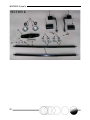
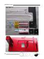
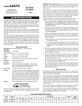
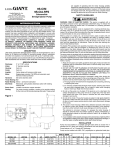
1
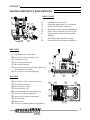
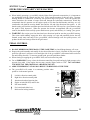
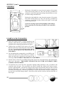
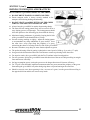
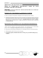
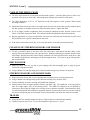
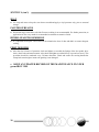
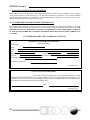
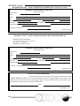
OPERATION, PARTS & SERVICE MANUAL MANUFACTURED BY Rev. 3 – 11/26/09 PRESIDENT’S MESSAGE On behalf of Wood Bay Turf Technologies and your local distributor, we thank you for purchasing the high performance greensIRON 3900. You are rolling in the right direction for smooth and fast greens! Introducing a greensIRON into the turf maintenance program at your course will provide many important benefits. In the development of the greensIRON 3900, our engineers were thinking about the needs of your course. We’ve met the many challenges and unconventional requirements of turf managers by working with superintendents and their staff. You can be assured the smoothest putting greens, increased green speed, and decreased mowing frequency are all very important benefits received when you iron your greens with Wood Bay’s 3900. The greensIRON 3900 will improve the putting surface after aeration and/or top dressing and allow an increase in mowing heights to reduce turf stress. Meet your expectations with superior equipment manufactured by Wood Bay Turf Technologies. The greensIRON Turf Broom is a very popular attachment for enhancing putting surfaces after top dressing. It will decrease your labor costs and is one of numerous customer suggestions developed into smart design solutions for greensIRON owners. The greensIRON Turf Ventilator also lets you improve air and water penetration in your greens without any player interruption. We are manufacturers of eco-friendly products. The greensIRON light kit allows staff to get that early start and we began offering an electric start option for additional operator convenience. We urge you to read this manual carefully. The instructions and recommendations for operating the greensIRON 3900 will help assure the safe and enjoyable use of this equipment. Thank you for choosing the greensIRON 3900. D. Lyall Adams President 1 INTRODUCTION The purpose of this manual is to provide you with reference information and assistance in setting up, maintaining and operating your greensIRON 3900 in a safe, effective and efficient manner. It is intended for turf rollers powered with the Hydro-Gear hydrostatic transmission. We expect that this manual will answer most of your questions, but Wood Bay encourages you to contact your local distributor or Wood Bay’s Technical Service Center on our toll free line (available in North America at 1-800-661-4942) for further assistance or clarification at any time. The manual alerts you to safety and environmental considerations, special features of the greensIRON 3900, operations, ironing techniques, adjustments, servicing, trouble shooting and replacement parts identification. It also introduces you to the special attachments and accessories that you may obtain to increase the benefits of turf rolling in maintaining and enhancing your greens, both in terms of turf health and putting performance for your golfers. We strive for not only what could be, but what should be in your turf management program. Please note that the information, illustrations and specifications contained in this manual are based on the latest product information available at the time of printing this manual. Wood Bay Turf Technologies reserves the right to make changes at any time, without notice, in specifications and models and also to discontinue models. The right is also reserved to change any specifications or parts at any time without incurring any obligation to install the same equipment on models manufactured prior to the date of such change. The illustrations used in this manual may not depict actual models or equipment and are intended as representative views for reference only. 2 TABLE OF CONTENTS PRESIDENT’S MESSAGE ............................................................................................................................. 1 INTRODUCTION ............................................................................................................................................ 2 TABLE OF CONTENTS ................................................................................................................................. 3 SECTION 1 ........................................................................................................................................................ 4 WARNINGS-SAFETY CONSIDERATIONS ...................................................................................... 4 SECTION 2 ........................................................................................................................................................ 5 MAJOR COMPONENT DESCRIPTIONS .......................................................................................... 5 FRONT VIEW ............................................................................................................................. 5 SIDE VIEW ................................................................................................................................. 5 TOP VIEW .................................................................................................................................. 5 SECTION 3 ........................................................................................................................................................ 6 FEATURES ............................................................................................................................................. 6 SECTION 4 ........................................................................................................................................................ 7 ASSEMBLY AND SET UP .................................................................................................................... 7 ASSEMBLY INSTRUCTIONS .................................................................................................. 7 SET UP PROCEDURES ............................................................................................................. 8 SECTION 5 ...................................................................................................................................................... 10 OPERATION .........................................................................................................................................10 BEFORE STARTING YOUR greensIRON 3900 TURF ROLLER .......................................10 STARTING HONDA MOTOR .................................................................................................10 OPERATOR FAMILIARITY WITH MACHINE ..................................................................11 PEDAL CONTROL ...................................................................................................................11 STEERING .................................................................................................................................12 LOADING AND UNLOADING ...............................................................................................12 IRONING TECHNIQUES AND PRACTICES .......................................................................13 SECTION 6 ...................................................................................................................................................... 14 SERVICING AND MAINTENANCE..................................................................................................14 HYDROSTATIC TRANSMISSION and HYDRAULIC MOTOR .......................................14 MONITORING THE HYDROSTATIC TRANSMISSION PERFORMANCE ..................14 CARE OF THE DRIVE CHAIN...............................................................................................15 CLEANING OF STEERING ROLLERS AND TRAILER ....................................................15 DRIVE ROLLER .......................................................................................................................15 STEERING ROLLERS AND HANDLE BARS ......................................................................15 TRAILER....................................................................................................................................15 SEAT ...........................................................................................................................................16 PAINTED SURFACES ..............................................................................................................16 HYDRO-GEAR TRANSMISSION ..........................................................................................16 FIRST 20 HOURS ......................................................................................................................16 ENGINE MAINTENANCE.......................................................................................................17 SECTION 7 ...................................................................................................................................................... 18 TROUBLE SHOOTING .......................................................................................................................18 SECTION 8 ...................................................................................................................................................... 21 PARTS LIST AND ILLUSTRATIONS ...............................................................................................21 SECTION 9 ..................................................................................................................................................... 39 WARRANTY .........................................................................................................................................40 FOR LOCAL SALES .................................................................................................................47 3 SECTION 1 WARNINGS-SAFETY CONSIDERATIONS PLEASE OBSERVE ALL WARNING STICKERS LOCATED ON THE EQUIPMENT. WARNING INDICATES A STRONG POSSIBILITY THAT EQUIPMENT DAMAGE OR PERSONAL INJURY COULD OCCUR WITH IMPROPER USE. REMEMBER SAFETY FIRST! * * * * * * * * * * * * WARNING Ensure that the trailer is attached to the transport vehicle before unloading or loading the greensIRON. WARNING Keep all person(s) clear when towing unit because the TRAILER MAY BE WIDER THAN TOW VEHICLE. WARNING Learn how to stop the Honda motor quickly, and understand the operation of all controls. Never permit anyone to operate the greensIRON without proper instructions and initial training at slow speeds. WARNING Do not over fill the fuel tank. There should be no fuel in the filler neck. If any fuel is spilled, clean it up completely and allow petroleum vapor to dissipate before starting the motor. Refuel in a well-ventilated area with the motor stopped; do not smoke or allow flame or sparks in the area. Gasoline is highly flammable and explosive under certain conditions. Close the filler cap securely. WARNING The exhaust muffler becomes hot during operation and remains hot for a period of time after stopping the engine. Be careful not to touch the exhaust muffler while it is hot. WARNING Children or passengers must not be allowed to ride on the greensIRON or trailer. WARNING Be aware of and avoid severe grades and unusual undulations, as well as adjacent sand traps and water features (this also applies to loading and unloading). Ensure paths, gates and bridges can accommodate width of trailer. WARNING Start and stop the motor from a seated position when possible, and ensure pedals are in the neutral position to avoid any unexpected movement. WARNING Be aware of the local conditions that you are operating under. The greensIRON may have less traction on wet turf, and on higher cut turf. WARNING Ensure that the motor is shut off prior to servicing any component under the safety guards, deck, transmission, motor coupling, or the motor itself. WARNING Wear suitable protective clothing and sunscreen so as to prevent eye damage, hearing impairment and sunburn. WARNING Sudden release of the forward clutch pedal will result in the gradual slowing down/ stopping of the greensIRON. Engaging the opposite clutch pedal while the greensIRON is in motion will result in the sudden or immediate stop of the drive roller and could cause personal injury and possible bruising of the turf. Always train on the equipment at slow speeds. TO VALIDATE THE greensIRON 3900 WARRANTY, COMPLETE THE SAFETY ACKNOWLEDGEMENT AND WARRANTY FORMS PROVIDED AND RETURN TO WOOD BAY TURF TECHNOLOGIES (see Pages 42 and 44). 4 SECTION 2 MAJOR COMPONENT DESCRIPTIONS FRONT VIEW 1 2 25 3 22 19 4 5 24 21 25 6 7 1 2 3 4 5 6 7 8 Soft Hand Grips (each side) Handle Bar Adjustment Lever (Not Shown) Honda GX160 K1QX 5.5 hp Motor Manual Recoil Starter and Hour/RPM Meter Engine Switch (ON/OFF) & Oil Alert Light Steering Rollers (Galvanized Tapered/NonRidging) Drive Roller (Super Turf Trac Coating) Optional Electric Start (Battery Not Shown) SIDE VIEW 9 10 11 12 13 14 15 High Back Seat c/w Drain Hole Steering Column Cowling and Cover Transmission Cover Drive Chain and Sprocket Drive Roller Bearings Super Turf Trac covering (Disperses Water and Provides Positive Traction) Drive Roller Tapered (Non-Ridging) 9 23 10 greensIRON 11 13 13 12 TOP VIEW 16 17 18 19 20 21 22 23 24 25 greensIRON - Trailer Locking Latch Bar Non-Slip Deck Surface Direction Pedal - Right Direction Pedal - Left Seat Forward/Reverse Adjustment Lever Optional Turf Broom Attachment Optional Turf Ventilator Attachment Optional Lights Bumper Pads Accessories Attachment Bracket (Not Shown) 14 15 24 17 15 16 24 18 19 3 20 5 SECTION 3 FEATURES UNMATMATCHED QUALITY AND COMMITMENT: PERFORMANCE EVERY DAY Precision engineered components in each greensIRON produce amazing operator satisfaction from start to finish. Unique and dynamic steering system for straight tracking over flat to undulating greens. High back padded seat with slide adjustment for maximum operator comfort and support. Minimal day to day maintenance requirements combined with the new low torque powerful Hydro-Gear hydrostatic transmission and hydraulic motor. Customers can expect longer life with less maintenance. Machined and tapered galvanized steel steering rollers give both maximum durability and aesthetic appeal. Minimal vibration levels and comfortable seat improves productivity and significantly reduces operator fatigue. The Super Turf Trac drive roller covering provides increased high performance traction when you need it in severe undulating conditions. Produces a soft touch effect for putting. Reduced scuffing on collars. Industrial bearings, with convenient access to grease ports. Powerful and economical to operate Honda GX160 UTQX26 5.5 hp engine. Multi-purpose transport trailer complete with extra long tailgate ramp is designed for fast, trouble–free loading and unloading. Highest quality rust protection liner throughout trailer. Convenient and easy to locate main drive components including: hydrostatic pump oil reservoir, drive sprockets, drive coupler, hydrostatic transmission, hydraulic motor, Honda motor and drive chain adjustments. Factory installed oil drain hose and tap for easy and efficient servicing of Honda motor. Optional 25-watt magneto lighting system for “night time” illumination. Optional Turf Broom attachment will create a perfect finish to greens following top dressing. Optional Turf Ventilator available when fast and efficient aeration is required on greens and tees. Optional, side-loading trailer (special order) for courses with narrow pathways, gates and bridges. Optional electric Honda motor start for extra convenience. Limited one year warranty on parts and labor. Owning a greensIRON 3900 is rolling in the right direction! 6 SECTION 4 ASSEMBLY AND SET UP ASSEMBLY INSTRUCTIONS 1. Remove all packaging and crating materials except the bottom pallet. 2. Remove and unpack fenders (2), wheel hub and axle assemblies (2), tow bar for trailer (1), and seat for the greensIRON 3900 turf roller. 3. If the optional Turf Broom and/or Turf Ventilator attachment kits are included in your order (see packing slip and notations on crate), remove, and assemble them separately. The Turf Ventilator is assembled, and the Turf Broom has been assembled in part, at the manufacturing plant prior to shipping. The hardware package and instructions are enclosed. The right and left support brackets can stay permanently bolted to the side of the greensIRON. 4. Located under the transmission cover is the hardware (bolt package) and operations manuals (including the greensIRON 3900, Honda engine, Hydro-Gear hydrostatic transmission and hydraulic motor) with their warranty registration forms. 5. Remove the two locking pins and lower tailgate down to the floor surface. Place cardboard or packing material between the floor and tail gate to prevent scratching/paint damage. 6. Lift the roller-locking pin at the front of the trailer, releasing the greensIRON 3900, and insert it back in the holder slot. Slowly roll the greensIRON out of the trailer box and down the ramp. Remove the pallet from under the trailer. 7. Raise the tail gate and insert both locking pins. Tip the trailer box to rest on the tail gate for the next part of the assembly. Install the trailer fenders with eight (8) 3/8” x 1” bolts, nuts and washers prior to installing axels and wheels. 8. Insert the axle tube assemblies (2) into the sides of the trailer box. Ensure that hub is positioned above the axle tube to maintain a low trailer elevation. Attach securely with four (4) of the 1/2” x 2 3/4” bolts, washers and nuts (nuts facing the rear). If it is difficult to push the bolts through the holes, try switching the axle tubes from one side to the other. 9. Mount wheels to the hubs with wheel lugs provided. The bearings have been serviced and packed, and are ready for operation. Check the tire pressure. Since the trailer has no springs, eight to ten (8-10) psi is recommended for most conditions. 10. Secure the trailer tow bar to the trailer box, using two (2) of the 1/2” x 2 3/4” bolts, washers and nuts. Ensure that when installed the tow bar curves upwards at the towing machine. Tip the trailer back down on its wheels. The trailer is now ready for use. Note: the tow bar should always be firmly connected to a towing machine before attempting to reload the greensIRON 3900 turf roller. When connected to the towing unit, the bar and trailer box should be parallel with the ground. 7 SECTION 4 (con’t) 11. Loosen the handle bar clamp; turn the handle bars up so the hand grips are in a vertical position. Tighten adjustment lever. Note: The position of the handle bars may be adjusted to meet operator preference using the handle bar lever; caution: do not wear the knarling on the handle bar clamp. 12. Install the seat with its slide frame onto the turf roller seat brackets, and secure with the four (4) 5/16” nuts and lock washers provided. Tilt the seat forward prior to opening transmission cover. NOTE: greensIRON 3900 is shipped without motor and transmission lubricants, or fuel. 13. Refer to the enclosed Honda motor owner’s manual; fill the motor to the correct level with the recommended lubricant. Use high detergent, premium quality oil for the motor. The Honda manual recommends SAE 10W 30 for general, all temperature use. 14. Fill the fuel tank with unleaded fuel. Do not overfill. 15. Pour approximately three (3) liters of Mobil 1 5W40/50 synthetic oil into the Hydro-Gear transmission tank. Do not fill over/above the sight glass. 16. Lubricate the drive chain as required – see Maintenance Schedule. 17. Grease as required the steering roller pivot (1) and drive roller bearings (2). Now that your greensIRON 3900 is completely assembled, refer to the “Set Up Procedures” before moving onto the green. SET UP PROCEDURES 1. Your greensIRON 3900 does not have a throttle cable. Prior to normal operations, set the Honda motor throttle lever for preferred RPMs. Initially, RPMs should be set low until the operator is familiar with the operations of the machine. Once training and familiarization with the equipment is complete, RPM’s may be increased (maximum 3650) for faster greensIRON speeds. See RPM digital tach located on motor. 2. The drive chain tension has been preset at the factory. During assembly the greensIRON 3900 may require minor adjustment. To make an adjustment, loosen the ½ inch nut on the idler sprocket and slide the sprocket in the direction required to ensure a ¼ inch deflection at the center of the chain. It will feel quite tight. Ensure that the chain is lubricated regularly. 3. All steering end roller bearings come pre-packed with grease. After one months operation apply additional grease sparingly. Recheck all nuts, screws and set screws to ensure that none have loosened during transport. Your greensIRON 3900 is now ready to operate. 8 SECTION 4 (con’t) Comment We trust that these instructions have enabled you to assemble and get to know your greensIRON 3900 turf roller. If you have suggestions, questions, or wish to comment on the instructions, please let us know; in North America telephone 1-800-661-4942 or 780-468-4378, e-mail at [email protected] or fax comments to 780-468-0059. We appreciate your assistance and thank you for choosing one of Wood Bay’s innovative products, the greensIRON 3900. For further information contact your local distributor or the manufacturer Wood Bay Turf Technologies, 1-800-661-4942. www.woodbayturftech.com 9 SECTION 5 OPERATION BEFORE STARTING YOUR greensIRON 3900 TURF ROLLER Refer to your Honda motor, Hydro-Gear hydrostatic transmission, and the hydraulic motor owner’s manuals for start up and break-in recommendations. Check oil levels in both Honda motor and Hydro-Gear oil reservoir. Check fuel level (unleaded fuel is recommended). Check drive chain adjustment. Chain may require tightening after initial operation on golf course. Lubricate chain frequently. Check on both sides of the greensIRON prior to operation to ensure there are no obstructions that could tear the Super Turf Trac drive roller covering. STARTING HONDA MOTOR Turn the fuel switch to the ON position. Turn the motor switch to the ON position. Engage the choke switch if required. Pull the starter recoil handle (it is recommended that the operator start the engine while seated on the greensIRON). Ensure both foot pedals are in the neutral position. Once the motor is running, shut off the choke switch and adjust throttle speed. Set the throttle speed manually with engine throttle lever. To stop motor, turn ON/OFF switch to the OFF position, and close OFF fuel switch. 1 2 3 4 5 6 10 Fuel switch Choke Manual throttle lever Engine switch Pull start handle Hour/RPM meter (not shown) SECTION 5 (con’t) OPERATOR FAMILIARITY WITH MACHINE When initially operating a greensIRON with the Hydro-Gear hydrostatic transmission, it is important to get comfortable with the controls and the "feel" of the smooth operation of this turf roller. Operator training should be conducted at a relatively low-speed on large level greens. Since the speed of the motor determines the amount of torque delivered through the hydrostatic transmission, Wood Bay recommends that all operators set the engine speed to less than one-half throttle until they are very comfortable with both the steering handle bars and the left and right directional foot pedals. A low throttle setting will limit the maximum speed at which the turf roller will travel in a given direction when the pedal is fully depressed. When the operator has become accomplished with the greensIRON controls, the throttle can be set fully open to both increase speed, and efficiency in “ironing” your greens. WARNING: Do not jam your foot down hard on a directional pedal to start the greensIRON moving. This action could suddenly engage the drive roller causing it to spin and potentially bruise the turf. Smooth, steady starts and stops of the greensIRON, effected through even foot pedal pressure, will produce the best turf ironing results for the golf course. PEDAL CONTROL DO NOT DEPRESS BOTH PEDALS AT THE SAME TIME, as clutch linkage damage will occur. Depress the pedal smoothly and steadily for the desired direction of travel; left pedal for left travel; right pedal for right travel (reference to left and right side of the greensIRON is determined while seated on the unit looking forward). To increase ground speed, press the pedal down further. When slowing or stopping the greensIRON 3900, ease back on the foot pedal. For an EMERGENCY stop, release the direction-controlling foot pedal and apply light pressure to the opposite foot pedal. If the engine does not stop, turn the engine switch to “Off”. DO NOT DRAG YOUR FEET ON THE GROUND AS A BRAKING DEVICE. ABRUPT EMERGENCY STOPS MAY RESULT IN BRUISING OF THE TURF. The greensIRON will remain in a stationary position when pedals are in the neutral position. 1 1 2 3 4 5 6 7 Left drive direction control pedal Right drive direction control pedal Aluminum checkered traction plate Engine switch (ON/OFF) and oil alert Pull starter handle Fuel switch and choke lever Roller-trailer locking latch bar 2 3 4 5 6 7 Left Roll (unload) Direction Right Roll (loading) Direction 11 SECTION 5 (con’t) STEERING Pushing the left handle bar away from the operator will pivot the front of the steering rollers out. This will cause the greensIRON to commence a turn to the right when rolling in that direction, or to the left when rolling in that direction. Pushing the right handle bar away from the operator will pivot the back of the steering rollers out. This will cause the greensIRON to commence a turn to the left when rolling to the right, or to the right when rolling to the left. Avoid over steering to prevent the possibility of turf damage. This is especially true when the greensIRON is in a stationary position. LOADING AND UNLOADING 12 Ensure the transport trailer is securely attached to the transport vehicle and the greensIRON locking latch is engaged before transporting equipment to the green. Transport the greensIRON to the green to be ironed. Back the trailer unit towards the green so that when the tail gate is lowered it will rest evenly on the edge of the collar. DO NOT BACK THE TRAILER ON TO THE GREEN. For side-loading units, transport the greensIRON to the collar of the green to be ironed, and stop at a distance where the gate can be lowered to rest evenly at the collar edge. DO NOT DRIVE TRAILER ON TO THE GREEN. Start the motor, release the greensIRON locking latch, depress the left pedal and drive the unit down the ramp on to the green. FOR SAFETY REASONS DO NOT OVER ACCELERATE WHEN LOADING OR UNLOADING. To reload the unit, reverse the above procedures aligning loading markings on the greensIRON with centerline on the tail gate. The greensIRON can only be loaded and secured to the trailer from the operator’s right hand side. The non-slip coating on the tail gate ramp and trailer deck provides excellent traction when loading. Line up the greensIRON with the trailer and drive up the tail gate. Do not over accelerate, and stop gently. Once the greensIRON is in place on the trailer, insert the locking pin to prevent roller movement during transport. Shut off the motor and fuel switches, and latch both sides of the tail gate. SECTION 5 (con’t) IRONING TECHNIQUES AND PRACTICES DO NOT REFUEL greensIRON WHILE ON THE GREEN. DO NOT DRIVE TRAILER ON GREENS OR TEES. Ensure transport trailer is always securely attached to the transport vehicle during loading and unloading. DO NOT LEAVE greensIRON SITTING ON THE GREEN SURFACE FOR LENGTHY PERIODS OF TIME. Always have the greensIRON in motion when turning sharply. The most efficient ironing pattern likely will be to travel across a steep sloping green at a slight angle. The ironing pattern should allow the operator to face oncoming play from down the fairway. Maximum ironing performance is gained by keeping the left side of the greensIRON on the downhill side of a slope. Prevent creasing, marking or ridging. Adjust the ironing pattern to accommodate any sharp undulations in green surface. Steer the roller into a steep slope along the periphery of a green, minimizing the chance of creasing on the low side of the greensIRON. Be aware of bunkers, steep drops or water features adjacent to greens. The preferred ironing effect for putting is obtained at a travel speed of 1000 sq. ft. per min. (5-7 mph). Iron green in the direction that allows the Turf Broom to contact top dressing before the rollers. For superior results, drive greensIRON with the Turf Ventilator in the forward position. For new operators, driving the greensIRON toward the direction of the sun will help travelling in straight lines and increase efficiency. On large rectangular greens, ironing the green over the longest direction will increase efficiency. For TV golf events and other important tournaments make two passes around the periphery of the green. Start turning the greensIRON early when both going down a slope and turning at the same time. Should a crease(s) occur when operating in low, wet areas of a green, iron the green while travelling in the opposite direction and this will remove strip marks. 13 SECTION 6 SERVICING AND MAINTENANCE PRIOR TO UNDERTAKING MAINTENANCE greensIRON 3900, SHUT OFF MOTOR. WORK ON YOUR CAUTION: GASOLINE AND/OR OIL SPILLED OR TRACKED ON TO TURF MAY CAUSE SEVERE DAMAGE. HYDROSTATIC TRANSMISSION and HYDRAULIC MOTOR Refer to your Hydro-Gear hydrostatic and hydraulic motor transmission owner’s manuals. The Hydro-Gear hydrostatic transmission provides a smooth, powerful and quiet operation. It has been checked and adjusted at the factory to ensure it performs effectively, and that the clutch pedals return to their neutral (i.e., full stop) position when released. Add approximately three (3) liters of Mobil 1 5W40/50 synthetic oil to the reservoir. Change oil and filter after 100 hours and every 400 hours or annually thereafter. MONITORING THE HYDROSTATIC TRANSMISSION PERFORMANCE Monitor closely the cleanliness of the fan and cooling fins. The transmission may be cleaned with a pressure washer, but the input and output shaft seals are never to be sprayed directly. Direct pressure wash spraying can damage the seals. Such damage will not be covered under warranty. Check temperature and oil levels on reservoir site gauge. Performing regularly scheduled maintenance will keep your greensIRON running in top condition. 14 SECTION 6 (con’t) CARE OF THE DRIVE CHAIN The drive chain should be re-tensioned and lubricated regularly. Lubricate chain before or after every operation with a spray-on chain lube - lubricating chain regularly will extend life of the chain. The chain should have a 3/8” to 1/2” deflection on the side opposite to idler sprocket, under normal operating conditions. Should the chain become too loose or too tight, loosen the axle bolt on the idler sprocket and then adjust the idler sprocket as needed to increase or reduce the chain tension. Tighten axle bolts. If it is no longer possible to tighten the chain as needed by adjusting the idler sprocket, remove a half link or a full link to shorten the chain. The chain should then be adjusted to the preferred tension. Regular applications of a spray-on chain lube will ensure the chain does not become dry and will avoid the possibility of oil or grease contamination on the turf. If the chain is allowed to become dry, it will cause the chain to wear and/or break prematurely. CLEANING OF STEERING ROLLERS AND TRAILER Tilt the greensIRON down on the drive roller side and remove sand, thatch and other debris on the steering rollers and undercarriage with a pressure hose. Wash the sand and grass material from the trailer while empty. Keeping the trailer clean will help extend the life of the traction surface on the drive roller and enhance the appearance and longevity from the tough abrasion. The liners are great looking with a fine textured finish. DRIVE ROLLER Inspect the drive roller for any dirt or grass clippings and clean thoroughly prior to going on green. Clean with a high powered hose. Using a lithium II or non high-temp grease, lubricate both bearings every 20 hours of operation. STEERING ROLLERS AND HANDLE BARS Inspect the rollers for any dirt or grass clippings and clean them prior to traveling on the green. Using a lithium II or non high-temp grease, lubricate bearings every 50 hours of use. Check periodically for correct steering roller/handle bar alignment. Steering rollers must be aligned parallel with the right deck edge. The handle bar in driving position must be at right angles (90) to the steering rollers. The handle bar alignment can be adjusted by increasing or decreasing the length of the steering rod arm connector assembly, located under the deck. To make an adjustment in the handle bar alignment requires disconnecting at least one rod end, releasing the jam nut, and turning the rod end toward or away from the other rod end on the connector assembly. TRAILER Using lithium II or non-high temperature grease, lubricate the two wheel bearings annually. Check tire pressure prior to use. Tire pressure should be kept between 8 - 10 psi. 15 SECTION 6 (con’t) SEAT Use soap and water to keep the seat clean as needed and apply a vinyl protector only, prior to seasonal storage. PAINTED SURFACES Wash with soapy water and a soft cloth. Pressure washing is not recommended. For further protection, an application of wax every month is recommended to maintain an attractive finish. HYDRO-GEAR TRANSMISSION It is important to keep the veins (vents) of the transmission clear of dust and debris to ensure adequate cooling. FIRST 20 HOURS After the first 20 hours of operation, check and tighten, as needed, the linkage of the foot pedals, drive chain, wheel bolts and motor mounts. Also check and tighten as needed all key ways and set screws. This procedure should be conducted every 50 hours thereafter. Check and ensure the steering handle bar clamp bolts remain tight to ensure the gnarling is not damaged. KEEP AN UPDATED RECORD OF THE MAINTENANCE ON YOUR greensIRON 3900. 16 SECTION 6 (con’t) ENGINE MAINTENANCE Oil Reduction Case Oil Check oil level prior to each use. Check oil level prior to each operation. Change oil after first 20 hours use and then every Change oil after first 20 hours of use and then 100 hours thereafter. every 100 hours thereafter. Air Filter Check prior to each use. Clean every 50 hours. Replace every year or 300 hours. Sediment Cup Clean every 100 hours. Spark Plug Replace every year or 300 hours. Fuel Tank and Filter Clean every 100 hours. Refer to separate Honda Engine Owner Manual for specific parts and any other inquiries. MAINTENANCE SCHEDULE The greensIRON 3900 has been equipped with a Tiny Tach hour meter to aid you in maintaining your unit in top condition. Each Use Chains – lubricate Chains – check tension Transmission Reservoir Hydrostatic Transmission Filter Rollers – wash/rinse Drive Roller – grease bearings Steering Roller – grease Trailer – grease Trailer – tire pressure Check & tighten the linkage of the foot pedals, fan belt, drive chain, wheel bolts and motor mounts. Check & tighten as needed all keyways and set screws. Honda Motor √ Oil Air filter Reduction Oil Case Sediment Cup Spark Plug Fuel Tank and Filter √ 20 Hours 50 Hours 100 Hours 400 Hours Annually or Prior to Storage √ √ √ Change Change Change Change √ √ √ √ √ √ √ Change √ Change Clean Change Replace Change Clean Replace Clean 17 SECTION 7 TROUBLE SHOOTING TROUBLE SHOOTING SYMPTOM Honda motor runs rough. PROBABLE CAUSE SOLUTION Choke on. Switch off choke. Dirty air filter. Clean or replace filter. Intermittent spark. Clean or replace spark plug. Improper fuel mixture. Readjust—see Honda motor manual. Honda motor cuts out when changing throttle speed. Oil level low. Fill to correct level—see Honda manual. Fuel level low. Fill fuel tank. No movement left or right when pedals are depressed. Chain is broken. Replace chain. Adjust tension until desired movement is obtained. Jerky motion or chain is jumping. Not enough tension in chain. Adjust chain tension as explained in Section 5. Pedal movement is either too free or is difficult to depress. Tension on nylock nuts for the linkage arms may need adjustment. Adjust tension on nylock nuts until a comfortable pedal motion is obtained. Rattling, grinding type of noise from under deck when turf roller is moving. Chain may be loose. If chain is rubbing deck, ensure it is tightened and properly aligned. A steering bearing may be failing. Lift unit and hand turn rollers to check for noise; grease and/or replace bearings as needed. Bolts may be loose on moving parts. Check and tighten bolts as needed on: Drive roller pillow blocks Pedal linkages Steering roller end bolts/housings Stopper bolts on top of steering frame Roller continues traveling after release of pedals to neutral position. The connection to rocker arm needs adjustment to balance the return distance for both sides. See Section 5, adjusting for roller creep Transmission may over heat and feel sluggish, going both left and right to operator. Transmission oil and filter have not been changed. Change filter and oil. 18 SECTION 7 (con’t) TROUBLE SHOOTING SYMPTOM PROBABLE CAUSE SOLUTION Low oil in reservoir Fill to proper oil level With pedal depressed and throttle open, roller needs to be pushed to start moving. Failure of Hydrostatic motor or pump Change Hydrostatic pump or motor Transmission is running extra hot, shortly after starting it up. Low oil Filter needs to be changed due to poor oil flow Fill to proper oil level Change filter greensIRON Left Side View: Honda Motor and Hydro-Gear Pump 19 SECTION 7 (con’t) greensIRON Pump Reservoir and Filter greensIRON Real View: Drive Sprocket, Chain and Pump Reservoir 20 SECTION 8 PARTS LIST AND ILLUSTRATIONS Clutch Components - Section K Item Description Quantity Part # 1. 2. 3. 4. 5. 6. 7. 8. 9. 10. 11. 12. 13. Pedal Pads Clutch Pedal - Left Clutch Pedal - Right Clutch Pedal Bushing Foot Pedal Linkage Rod End (3/8" NF - Female RH) Rod End (3/8" NF - Female LH) Jam Nut (3/8" NF RH) Jam Nut (3/8" NF LH) Transmission Rocker Arm (welded with #11) Engagement Arm Connecting Shaft (welded with #10) Snap Ring (5/8") Key (3/16" x 1 1/4") 2 1 1 2 2 2 2 2 2 1 1 1 1 39 K02 100 39 K01 101 39 K01 102 39 K01 103 39 K01 104 39 Y02 183 39 Y02 184 39 Y02 185 39 Y02 186 39 K01 105 39 K01 106 39 K02 107 39 Y02 187 14. Bearing and Housing (2 hole - 5/8") 2 39 K02 108 15. Clutch Pedal Assembly – Left Checkered (no pad) 1 39 K01 270 (serial # G3I102091 ongoing – not shown) 16. Clutch Pedal Assembly – Right Checkered (no pad) 1 39 K01 271 (serial # G3I102091 ongoing – not shown) 21 SECTION 8 (con't) 22 Section 8 (con’t) Body Components - Section O Item Description Quantity Part # 1. 2. 3. 4. 5. 6. 7. 8. Deck Serial Number Plate (under cowling) Decal Package: Caution Decal Package: Identification Decal Package: Striping Non-Skid Deck Surface Steering Column Cover and Screws (6) (Not Shown) Seat (not shown) 1 1 1 set 1 set 1 set 1 1 1 39 O01 109 39 O01 110 39 O01 111 39 O01 112 39 O01 113 39 O01 114 39 O01 115 39 O02 116 9. Rubber Bumper/Scuff Pad 2 39 O02 117 10. Aluminum Traction Plate 1 39 O01 272 23 SECTION 8 (con’t) SECTION O 24 SECTION 8 (con’t) Steering Column Components - Section P Item Description Quantity Part # 1. 2. 3. 4. 5. 6. 7. 8. 9. 10. 11. 12. 13. 14. 15. 16. 17. 18. 19. 20. 21. 22. Handle Bar Steering Hand Grips Steering Shaft Handle Bar Clamp Handle Bar Adjustment Lever Steering Arm for Under Deck (welded) Steering Rod Arm (3/8" x 4 1/4" NF) Rod End (3/8" female NF) Jam Nut (3/8" NF) Bearing and Housing ( 4-bolt 1.0") Bearing and Housing ( 2-bolt 1.0") Key (1/4" x 1/4" x 1.0") Bolt (3/8" x 1 1/2" NC) Flat Washer (3/8") Lock Washer (3/8") Nut (3/8" NC) Carriage Bolt (3/8" x 1 1/2" NC) Bolt (3/8" x 1 1/4" NC) Carriage Bolt (5/16" x 1" NC) Flat Washer (5/16") Lock Washer (5/16") Acorn Nut (5/16" NC) 1 2 1 1 1 1 1 2 1 1 1 1 4 8 8 6 2 2 2 1 1 1 39 P01 118 39 P02 119 39 P01 120 39 P01 121 39 P02 122 39 P01 123 39 P01 124 39 Y02 183 39 Y02 185 39 P02 125 39 P02 126 39 P02 127 39 Z02 193 39 Z02 195 39 Z02 196 39 Z02 197 39 Z02 198 39 Z02 194 39 Z02 208 39 Z02 203 39 Z02 204 39 Z02 205 25 SECTION 8 (con’t) 26 SECTION 8 (con’t) Steering Roller Components - Section Q Item Description Quantity Part # 1. 2. 3. 4. 5. 6. 7. 8. 9. 10. 11. 12. 13. 14. 15. 16. Steering Roller Frame Steering Roller Stub Axle Steering Roller Bearing Plate Spacer Flange and Bearing (4-bolt c/w 1" bearing) Bearing (1" c/w set screw collar) Pressed Flange (3-bolt) Snap Ring (1") Bolt (3/8" x 1 1/2" NC) Flat Washer (3/8") Lock Washer (3/8") Nut (3/8" NC) Bolt (5/16" x 3/4" NC) Flat Washer (5/16") Lock Washer (5/16") Carriage Bolt (3/8" x 1 1/2" NC) 1 2 4 1 1 4 8 1 4 8 8 4 12 12 12 4 39 Q01 128 39 Q01 129 39 Q01 130 39 Q01 131 39 Q02 132 39 Q02 133 39 Q02 134 39 Q02 135 39 Z02 193 39 Z02 195 39 Z02 196 39 Z02 197 39 Z02 202 39 Z02 203 39 Z02 204 39 Z02 198 27 SECTION 8 (con’t) SECTION Q 28 SECTION 8 (con’t) Engine Components - Section R Item Description Quantity Part # 1. 2. 3. 4. 5. 6. 7. 8. 9. 10. 11. 12. Honda 5.5 hp with Oil Alert Motor Vibration Mount Vibration Dampners Digital Tach Hour/RPM Meter Muffler Deflector and Screws Oil Drain Assembly 1 1 4 1 1 1 Bolt (5/16" x 1 1/2" NC) secures engine to mounting plate 4 Flat Washer (5/16") 8 Lock Washer (5/16") 8 Nut (5/16" NC) 8 Carriage Bolt (5/16" x 5/8" NC) 4 Electric Start Kit - All Components (Not Shown) 1 39 R02 136 39 R02 137 39 R02 138 39 R02 139 39 R02 140 39 R02 141 39 Z02 200 39 Z02 203 39 Z02 204 39 Z02 206 39 Z02 209 39 R02 253 13. 14. 15. Electric Start Honda Engine (Not Shown) Wiring Harness (Not Shown) Lights (Not Shown) 1 1 2 39 R02 254 39 R02 255 39 R02 256 16. Switch (Not Shown) 1 39 R02 257 17. Battery (Not Shown) 1 39 R02 258 18. Battery Box (Not Shown) 1 39 R02 259 29 SECTION 8 (con’t) SECTION R 30 SECTION 8 (con’t) Transmission Components - Section S Item Description Quantity Part # 1. 2. 3. 4. 5. 6. Chain Coupler Hub (#40 16 3/4" - Engine Side) Chain Coupler Hub (#40 16 5/8" - Pump Side) Key (3/16" x 1 1/4") Chain (#40 double) Chain Connector Martin Chain Cover (Includes: 2 O-rings, 4 bolts, 2 lock washers, 2 gaskets Hydrostatic Transmission Mounting Bracket Hydro-Gear 10 cc Piston Pump Hydraulic Motor Mount Hydraulic Motor c/w woodruff key (1/4" x 1.0") Reservoir (oil tank) Reservoir Breather Cap Sight Glass Filter head Filter (25 micron) 90˚ Bent Stern 1/2" Fitting 60˚ Bent Stern 1/2" Fitting Hose Clamps (to fit 1/2" suction hose) Reservoir 1/2" Drain Plug Suction Hose (1/2" x 6.0") Suction Hose (1/2" x 4.0") Return Hose (1/2" x 12.0") Pressure Hose (1/2" x 10.0") ORB Adaptor (hydraulic motor to pressure hose) ORB Adaptor (hydrostatic transmission to pressure hose) Transmission Cover (Not Shown) Rubber Catch (Not Shown) Engagement Arm Transmission Engagement Rod (5/16" x 5.0" NF) Rod End (5/16" - Female RH) AVM Dampner Neutral Return Spring Bolt (1/2" x 1 1/2" NC) Lock Washer (1/2") Nut (1/2" NC) Bolt (3/8" x 1 1/2" NC) Flat Washer (3/8") Lock Washer (3/8") Nut (3/8" NC) 1 1 2 1 1 1 39 S02 142 39 S02 143 39 Y02 187 39 S02 144 39 S02 145 39 S02 146 1 1 1 1 1 1 1 1 1 5 1 6 1 1 1 1 2 2 2 1 2 1 1 2 1 1 2 2 2 2 6 6 8 39 S01 147 39 S02 148 39 S01 149 39 S02 150 39 S01 151 39 S02 152 39 S02 153 39 S02 154 39 S02 155 39 S02 156 39 S02 157 39 S02 158 39 S02 159 39 S02 160 39 S02 161 39 S02 162 39 S02 163 39 S02 164 39 S02 165 39 S01 166 39 S02 167 39 S01 168 39 S01 169 39 S02 170 39 S02 171 39 S02 172 39 Z02 189 39 Z02 191 39 Z02 192 39 Z02 193 39 Z02 195 39 Z02 196 39 Z02 197 7. 8. 9. 10. 11. 12. 13. 14. 15. 16. 17. 18. 19. 20. 21. 22. 23. 24. 25. 26. 27. 28. 29. 30. 31. 32. 33. 34. 35. 36. 37. 38. 39 31 SECTION 8 (con’t) 40. 41. 42. 43. 44. 45. 46. 47. 48. 49. 32 Carriage Bolt (3/8" x 1 1/4" NC) Bolt (5/16" x 1" NC) Flat Washer (5/16") Lock Washer (5/16") Nut (5/16" NC) Nut (5/16" NF) Bolt (1/4" x 3/4" NC) Flat Washer (1/4") Lock Washer (1/4") Nut (8mm) 4 5 3 7 5 2 2 2 2 2 39 Z02 199 39 Z02 201 39 Z02 203 39 Z02 204 39 Z02 206 39 Z02 207 39 Z02 210 39 Z02 211 39 Z02 212 39 Z02 213 SECTION 8 (con’t) SECTION S 33 SECTION 8 (con’t) Main Drive Components - Section W Item Description Quantity Part # 1. 2. 3. 4. 5. 6. 7. 8. 9. 10. 11. 12. 13. Transmission Sprocket (#50 23T - 1.0" Bore) Drive Chain (#50 39") Drive Chain Connector #50 Idler Sprocket (#50 13T 1/2" Bore) Chain Adjuster Bracket Bolt (1/2" x 2.5" NC) Flat Washer (1/2") Lock Washer (1/2") Nut (1/2" NC) Carriage Bolt (3/8" x 1 1/4" NC) Flat Washer (3/8") Lock Washer (3/8") Nut (3/8" NC) 1 1 1 1 1 1 3 2 1 2 2 2 2 SECTION W 34 39 W02 173 39 W02 174 39 W02 175 39 W02 176 39 W01 177 39 Z02 188 39 Z02 190 39 Z02 191 39 Z02 192 39 Z02 199 39 Z02 195 39 Z02 196 39 Z02 197 SECTION 8 (con’t) Drive Roller Components - Section X Item Description 1. 2. 3. 4. 5. 6. 7. 8. 9. 10. 11. Drive Roller* Sprocket (#50 23T) Bearing and Housing (2-bolt PB 1.0") Key (1/4" x 1/4" x 1 1/4") Bolt (3/8" x 1 1/2" NC) Flat Washer (3/8") Lock Washer (3/8") Nut (3/8" NC) Glue & Covering Assembly Quantity Part # 1 1 2 1 4 8 4 4 1 39 X01 178 39 X02 180 39 X02 181 39 X02 182 39 Z02 193 39 Z02 195 39 Z02 196 39 Z02 197 39 X01 179 1 1 39 X01 273 39 X01 274 CAN BE ORDERED SEPARATELY – SEE BELOW Pebble Top Roll Covering Glue & Hardner SECTION X 35 SECTION 8 (con’t) Trailer Components - Section TT Item Description 1. 2. 3. 4. 5. 6. 7. 8. 9. 10. 11. 12. 13. 14. 15. 16. 17. 18. 19. 20. 21. 22. 23. 24. 25. 26. 27. 28. 29. 30. 31. 32. 33. 34. 35. Trailer Complete Trailer Body Trailer Tail Gate Tow Bar Tail Gate Latch Safety Latch Locking Pin Hinge Pin (for Tail Gate) Tail Gate Latch Mount Return Spring (for Tail Gate Latch) Trailer Clevis Cotter Pin (5/32" x 1 1/2") Cotter Pin (1/8" x 1.0") Fender Axle Support c/w Spindle Hub Rim (for Tire 18 x 8.50) Tire (18 x 8.50) Wheel Nut Dust Cap Tapered Bearing (1.0") Seal Bolt (1/2" x 2 3/4" NC) Nut (1/2" NC) Flat Washer (1/2") Lock Washer (1/2") Lock Nut (3/4" NC) Flat Washer (3/4") Nylon Lock Nut (3/8" NC) Flat Washer (3/8") Jam Nut (9/16") Curved Pin Striping (L & R) Decal (Not Shown) Caution Keep Hands Clear Decal (Not Shown) Caution Hook Up Trailer Before Unloading Decal (Not Shown) 3900 Decal (Not Shown) 3900 Tailgate Decal (Transparent) and (Not Shown) 36 Quantity 1 1 1 1 2 1 2 2 2 1 1 2 2 2 2 2 2 8 2 2 1 6 6 12 6 1 1 2 4 1 2 1 1 1 1 Part # 39 TT01 218 39 TT01 219 39 TT01 220 39 TT01 221 39 TT01 222 39 TT01 223 39 TT01 224 39 TT01 225 39 TT02 226 39 TT01 227 39 TT02 228 39 TT02 229 39 TT01 230 39 TT01 231 39 TT02 232 39 TT02 233 39 TT02 234 39 TT02 235 39 TT02 236 39 TT02 237 39 TT02 238 39 Z02 214 39 Z02 192 39 Z02 190 39 Z02 191 39 Z02 215 39 Z02 216 39 Z02 217 39 Z02 195 39 TT02 239 39 TT02 240 39 TT02 241 39 TT02 242 39 TT02 243 39 TT02 244 SECTION 8 (con’t) 37 SECTION 8 (con’t) Item Description Quantity Part Number Turf Broom Components—Section T 39 40 41 42 43 Turf Broom Package – Complete 1 30 T01 1000 Support Bracket—Right Support Bracket—Left Turf Broom Weight Bar Broom – 2” x 3 feet Wheel, caster with bearing Decal – Turf Broom Support Bolts, ½” x 1” Washer, ½” 1 1 1 3 2 1 4 4 30 30 30 30 30 30 1 30 V01 1000 V02 V02 T22 T13 T08 T02 WB WB 2680 2690 5880 6290 6600 275 8175 8770 Turf Ventilator Components—Section V Turf Ventilator – Complete 44 45 46 47 48 49 50 38 Support Bracket—Right Support Bracket—Left Weight Bar and Handle Assembly Shaft for Ventilator (Hexagonal)—not illustrated Turf Venting Blades Spacers Between Blades Spacers, Nylon for Outside Ends Bearing and Housing (2-bolt pillow block) Decal – Turf Ventilator Support Bolts, ½” x 1” NC Lock Washer, ½” 1 1 1 1 30 29 2 2 1 4 4 30 30 30 30 30 30 30 V02 V02 V05 V06 V06 V06 V06 WB 30 V02 WB WB 2680 2690 2740 2750 2760 2770 2780 7360 276 8175 8770 SECTION 8 (con’t) Light Kit Components - Section LK Item Description Quantity Part # 1. 2. 3. 4. 5. 6. 7. 8. 9. 25 Watt Lights Fly Wheel 25 Watt Coil (10.5") 25 Watt Coil (12") Wiring Harness (12") Wiring Harness (36") Switch Bolt (6mm x 30mm) Light Kit Complete 2 1 1 1 1 1 1 4 1 39 LK02 246 39 LK02 247 39 LK02 248 39 LK02 249 39 LK02 250 39 LK02 251 39 LK02 252 39 Z02 245 39 LK01 253 39 SECTION 9 WARRANTY greensIRON 3900 WARRANTY is provided as part of Wood Bay’s support program for customers who operate and maintain their equipment as described in this manual and other enclosed owner’s manuals. This warranty provides you with the assurance that Wood Bay will back this product where defects appear within the warranty period. Should the product be abused or modified to change its performance from original factory specifications, the warranty will become void. If you have any questions… Wood Bay Distributors are very interested in your complete satisfaction with the performance of your greensIRON 3900. In the event of a warranty or related servicing matter, we encourage you to contact your local distributor as soon as possible. Should the warranty or servicing problem not be resolved to you satisfaction, submit the matter to: Wood Bay Turf Technologies Toll free: 1-800-661-4942 (USA, Canada and Mexico) Or call: 1-780-468-4378 (USA, Canada, Mexico and International) 40 SECTION 9 (con’t) A. GENERAL PROVISIONS For the first twelve (12) months after the date of purchase, the manufacturer will repair or replace, as it elects, any part(s) defective in material or workmanship (except those specified in Sections B and C below) of a new greensIRON 3900 Turf Roller and/or Turf Broom and/or Turf Ventilator (the “Product”), as delivered to the original retail purchaser. This warranty applies only to purchases from authorized distributors and extends only to the original retail purchaser of the product. The performance of this warranty is dependant on receipt by Wood Bay Turf Technologies or Wood Bay Consulting Group Limited (hereinafter referred to as the “manufacturer”) of the warranty registration card from the original retail purchaser. B. ITEMS WARRANTED SEPARATELY This warranty does not apply to the Honda Motor, the Hydro-Gear hydrostatic pump, or the hydraulic motor, which are all covered by separate written warranties. C. ITEMS NOT COVERED The manufacturer is not responsible for the following: 1. Premium charged for overtime labor requested by the purchaser. 2. Transportation to and from the distributor’s office or service calls made by the distributor. 3. Used products. 4. Modification of any component or part of the product not supplied by the manufacturer or not performed on by the manufacturer or by an authorized distributor. 5. Depreciation or damage caused by normal wear, lack of reasonable and proper maintenance, failure to follow operating instructions, misuse, lack of proper protection during storage, or accident. 6. Normal maintenance and replacement of maintenance wear items, such as oil filters, chain, sprockets, bearings, drive roller covering and tires. D. PARTS REPLACED UNDER WARRANTY Only new or remanufactured parts or components furnished or approved by the manufacturer, will be used to repair the product. E. SECURING WARRANTY SERVICE To obtain performance of this warranty, the original retail purchaser must request warranty service from an authorized distributor. Present evidence that corresponds with the warranty registration card on date of delivery, and inform the distributor in what way the purchaser believes the product to be defective. F. NO IMPLIED WARRANTY OR OTHER REPRESENTATION Where permitted by law, neither the manufacturer nor any company affiliated with the manufacturer makes warranties, representations or promises as to the quality, performance or freedom from defect of the product covered by this warranty. NO IMPLIED WARRANTY OF MERCHANTABILITY OF FITNESS IS MADE. 41 SECTION 9 (con’t) G. LIMITATION OF PURCHASER’S REMEDIES Where permitted by law, the purchaser’s only remedies in connection with the breach or performance of any warranty on the product are those set forth on this page. In no event will the distributor, manufacturer or any company affiliated with the manufacturer be liable for incidental or consequential damages, including but not limited to loss of profit, rental of substitute equipment or other commercial loss. H. NO SUBDISTRIBUTOR OR DISTRIBUTOR WARRANTY The selling distributor makes no warranty of its own on any item warranted by the manufacturer and makes no warranty on any other item unless it delivers to the purchaser a separate written certificate specifically warranting the item. THE DISTRIBUTOR HAS NO AUTHORITY TO MAKE ANY REPRESENTATION OR PROMISE ON BEHALF OF THE MANUFACTURER, OR TO MODIFY THE TERMS OR LIMITATIONS OF THIS WARRANTY IN ANY PART. CUSTOMER RECORD COPIES TO REMAIN IN MANUAL WARRANTY REGISTRATION DETAILS (Please print clearly) Purchase Date: Owner: Address: City: Model No.: Engine No.: Selling Distributor: State/Province: Serial No.: Transmission No.: Code: Pre-Delivery Certification: (Distributor Signature) Customer Copy SAFETY ACKNOWLEDGEMENT I, _____________________________ acknowledge reading all pertinent safety and operational information enclosed and that the distributor has advised me of the locations and the reasons for all safety emblems on the machine. The distributor has also advised me on the safe operating procedures for the greensIRON 3900. This information will be made available to all other operators of the greensIRON 3900. Date: (Superintendent) Customer Copy 42 This page left intentionally blank 43 SECTION 9 (con’t) DISTRIBUTOR COPY - TO BE COMPLETED AND REMOVED AT POINT OF SALE WARRANTY REGISTRATION DETAILS (Please print clearly) Purchase Date: Owner: Address: City: Model No.: Engine No.: Selling Distributor: State/Province: Serial No.: Transmission No.: Code: Pre-Delivery Certification: (Distributor Signature) Distributor Copy WOOD BAY COPY - TO BE COMPLETED, REMOVED AND FORWARDED TO: Wood Bay Turf Technologies A Division of Wood Bay Consulting Group Limited 202, 8704 – 51 Avenue Edmonton, Alberta T6E 5E8 WARRANTY REGISTRATION DETAILS (Please print clearly) Purchase Date: Owner: Address: City: Model No.: Engine No.: Selling Distributor: State/Province: Serial No.: Transmission No.: Code: Pre-Delivery Certification: (Distributor Signature) Wood Bay Copy SAFETY ACKNOWLEDGEMENT I, _____________________________ acknowledge reading all pertinent safety and operational information enclosed and that the distributor has advised me of the locations and the reasons for all safety emblems on the machine. The distributor has also advised me on the safe operating procedures for the greensIRON 3900. This information will be made available to all other operators of the greensIRON 3900. Date: (Superintendent) Wood Bay Copy 44 This page left intentionally blank 45 46 PRODUCTS MANUFACTURED BY: Turf Technologies FOR LOCAL SALES & SERVICE INFORMATION CALL: 202 - 8704 51 Ave. Edmonton, Alberta Canada T6E 5E8 Toll Free: 1-800-661-4942 Direct: 1-780-468-4378 E-mail: [email protected] Web Site: www.woodbayturftech.com