1
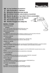
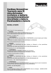
Cordless Screwdriver
Instruction Manual
F
Visseuse sans fil
Manuel d’instructions
D
Akku-Schrauber
Betriebsanleitung
I
Avvitatrice a batteria
Istruzioni per l’uso
Snoerloze schroevendraaier
Gebruiksaanwijzing
E
Atornillador a batería
Manual de instrucciones
P
Aparafusadora a bateria
Manual de instruço˜es
Akku skruemaskine
Brugsanvisning
S
Sladdlös momentskruvdragare
Bruksanvisning
N
Akku momentskrutrekker
Bruksanvisning
SF
Langaton ruuvinväännin
Käyttöohje
GR
∞Û‡ÚÌ·ÙÔ Î·ÙÛ·‚›‰È
√‰ËÁ›Â˜ ¯Ú‹Ûˆ˜
GB
NL
DK
6796D/6796FD
6797D/6797FD
6798D/6798FD
1
3
4
2
1
2
5
6
7
3
4
9
10
8
11
12
5
6
14
7
2
8
13
15
360
300
240
240
17
19
360
300
17
16
180
180
120
120
60
60
16
0
0
1
2
3
4
2
5
3
4
5
6
7
8
18
18
9
10
20
360
300
240
17
180
120
16
60
21
0
6
7
8
9
10
11
12
18
11
12
22
23
13
3
ENGLISH
1
2
3
4
5
6
7
8
Battery cartridge
Set plate
Bit
Sleeve
Graduations
Adjusting grip
Switch trigger
Light
Explanation of general view
9
10
11
12
13
14
15
16
Reversing switch lever
A side
B side
Clockwise
Counterclockwise
Warning lamp
Capacity limit of 6796D/FD
Range of fastening capacity
17
18
19
20
21
22
23
Revolution angle ( °)
Torque (Nzm)
Capacity limit of 6797D/FD
Capacity limit of 6798D/FD
Limit mark
Brush holder cap
Screwdriver
SPECIFICATIONS
Model
6796D/FD
No load speed (min–1) ................................................ 320
Fastening torque ....................................................... 1 – 5 N.m
Overall length ............................................................. 174 mm
Net weight ................................................................... 1.4 kg
Rated voltage ............................................................. D.C. 9.6 V
• Due to our continuing program of research and
development, the specifications herein are subject
to change without notice.
• Note: Specifications may differ from country to
country.
Safety hints
For your own safety, please refer to the enclosed
safety instructions.
IMPORTANT SAFETY INSTRUCTIONS
FOR CHARGER & BATTERY CARTRIDGE
ENC001-3
1. SAVE THESE INSTRUCTIONS — This manual
contains important safety and operating
instructions for battery charger.
2. Before using battery charger, read all instructions and cautionary markings on (1) battery
charger, (2) battery, and (3) product using
battery.
3. CAUTION — To reduce risk of injury, charge
only MAKITA type rechargeable batteries.
Other types of batteries may burst causing
personal injury and damage.
4. Do not expose charger to rain or snow.
5. Use of an attachment not recommended or
sold by the battery charger manufacturer may
result in a risk of fire, electric shock, or injury
to persons.
6. To reduce risk of damage to electric plug and
cord, pull by plug rather than cord when disconnecting charger.
7. Make sure cord is located so that it will not be
stepped on, tripped over, or otherwise subjected to damage or stress.
8. Do not operate charger with damaged cord or
plug — replace them immediately.
9. Do not operate charger if it has received a
sharp blow, been dropped, or otherwise damaged in any way; take it to a qualified serviceman.
4
6797D/FD
320
2 – 8 N.m
174 mm
1.4 kg
D.C. 9.6 V
6798D/FD
320
6 – 12 N.m
174 mm
1.4 kg
D.C. 9.6 V
10. Do not disassemble charger or battery cartridge; take it to a qualified serviceman when
service or repair is required. Incorrect reassembly may result in a risk of electric shock or
fire.
11. To reduce risk of electric shock, unplug
charger from outlet before attempting any
maintenance or cleaning. Turning off controls
will not reduce this risk.
12. The battery charger is not intended for use by
young children or infirm persons without
supervision.
13. Young children should be supervised to
ensure that they do not play with the battery
charger.
14. If operating time has become excessively
shorter, stop operating immediately. It may
result in a risk of overheating, possible burns
and even an explosion.
15. If electrolyte gets into your eyes, rinse them
out with clear water and seek medical attention right away. It may result in loss of your
eyesight.
ADDITIONAL SAFETY RULES FOR
CHARGER & BATTERY CARTRIDGE
1. Do not charge battery cartridge when temperature is BELOW 10°C (50°F) or ABOVE 40°C
(104°F).
2. Do not attempt to use a step-up transformer,
an engine generator or DC power receptacle.
3. Do not allow anything to cover or clog the
charger vents.
4. Always cover the battery terminals with the
battery cover when the battery cartridge is not
used.
5. Do not short the battery cartridge:
(1) Do not touch the terminals with any conductive material.
(2) Avoid storing battery cartridge in a container with other metal objects such as
nails, coins, etc.
(3) Do not expose battery cartridge to water or
rain.
6.
7.
8.
9.
A battery short can cause a large current flow,
overheating, possible burns and even a breakdown.
Do not store the tool and battery cartridge in
locations where the temperature may reach or
exceed 50°C (122°F).
Do not incinerate the battery cartridge even if
it is severely damaged or is completely worn
out. The battery cartridge can explode in a fire.
Be careful not to drop, shake or strike battery.
Do not charge inside a box or container of any
kind. The battery must be placed in a well
ventilated area during charging.
ADDITIONAL SAFETY RULES
FOR TOOL
3. Charge the battery cartridge with room temperature at 10°C – 40°C (50°F – 104°F).
Let a hot battery cartridge cool down before
charging it.
Installing or removing bit (Fig. 2)
CAUTION:
Always be sure that the tool is switched off and the
battery cartridge is removed before installing or
removing the bit.
Use only the driver bit or socket bit shown in the figure
below.
Do not use any other driver bit or socket bit.
ENB026-1
1. Be aware that this tool is always in an operating condition, because it does not have to be
plugged into an electrical outlet.
2. Hold tool by insulated gripping surfaces when
performing an operation where the cutting tool
may contact hidden wiring. Contact with a
‘‘live’’ wire will also make exposed metal parts
of the tool ‘‘live’’ and shock the operator.
3. Always be sure you have a firm footing.
Be sure no one is below when using the tool in
high locations.
4. Hold the tool firmly.
5. Keep hands away from rotating parts.
SAVE THESE INSTRUCTIONS.
OPERATING INSTRUCTIONS
Installing or removing battery cartridge
(Fig. 1)
• Always switch off the tool before insertion or
removal of the battery cartridge.
• To remove the battery cartridge, pull out the set
plate on the tool and grasp both sides of the
cartridge while withdrawing it from the tool.
• To insert the battery cartridge, align the tongue on
the battery cartridge with the groove in the housing
and slip it into place. Snap the set plate back into
place. Be sure to close the set plate fully before
using the tool.
• Do not use force when inserting the battery cartridge. If the cartridge does not slide in easily, it is
not being inserted correctly.
Charging
Before using battery charger, read all instructions and
cautionary markings on the battery charger.
Tips for maintaining maximum battery life
1. Always stop tool operation and charge the battery
cartridge when you notice that the warning lamp
lightened up.
2. Never recharge a fully charged battery cartridge.
Overcharging shortens the battery service life.
To install the bit, pull the sleeve in the direction of the
arrow and insert the bit into the sleeve as far as it will
go. Then release the sleeve to secure the bit.
To remove the bit, pull the sleeve in the direction of
the arrow and pull the bit out firmly.
Adjusting the fastening torque (Fig. 3)
Use an optional adjust grip to adjust the fastening
torque.
Insert the pins of the adjust grip into the holes in the
front of the tool. And then, turn the adjust grip so that
the torque gauge shows the desired torque by one of
the numbers from 1 to 12.
The number provides fastening torque in newtonmeter (N.m), and see below for the standard fastening
torque;
6796D/FD: 1 – 5 (Nzm)
6797D/FD: 2 – 8 (Nzm)
6798D/FD: 6 – 12 (Nzm)
After completion of the adjustment, always make trial
fastening about twenty times in order to keep stability
of torque. Then, check the fastening torque with a
torque tester before starting operation.
Switch action (Fig. 4)
CAUTION:
Before inserting the battery cartridge into the tool,
always check to see that the switch trigger actuates
properly and returns to the ‘‘OFF’’ position when
released.
To start the tool, simply pull the trigger. Release the
trigger to stop.
Lighting up front lamps (Fig. 5)
(for 6796FD/6797FD/6798FD only)
Pull the trigger to light up the front lamps. And the
lamps keep on lighting while the trigger is being
pulled. The light automatically goes out 10 to 20
seconds after the trigger is released.
5
Reversing switch action (Fig. 6)
MAINTENANCE
CAUTION:
• Always check the direction of rotation before operation.
• Use the reversing switch only after the tool comes to
a complete stop. Changing the direction of rotation
before the tool stops may damage the tool.
• When not operating the tool, always set the reversing switch lever to the neutral position.
This tool has a reversing switch to change the direction of rotation. Depress the reversing switch lever
from the A side for clockwise rotation or from the B
side for counterclockwise rotation. When the switch
lever is in the neutral position, the switch trigger
cannot be pulled.
CAUTION:
Always be sure that the tool is switched off and the
battery cartridge is removed before carrying out any
work on the tool.
Battery power warning lamp (Fig. 7)
The lamp lights up in red when the battery power
becomes low.
If you disregard the warning and continue operation,
the battery power will become not enough for the
normal performance of the tool, and soon the tool will
stop in order to avoid screwdriving with poor fastening
torque. And so, replace the battery by fully charged
one as soon as the red lamp lights up.
CAUTION:
The lamp may also light up in red before the battery
power becomes low under these conditions.
• Heavy load under which clutch mechanism does not
work. Do not use the tool in this condition.
(See the list of the capacity limit.)
Screwdriving operation (Fig. 8)
Place the point of the driver bit in the screw head and
apply pressure to the tool. Then switch the tool on.
When the clutch cuts in, the motor will stop automatically. Then release the switch trigger.
NOTE:
Make sure that the driver bit is inserted straight in the
screw head, or the screw and/or bit may be damaged.
Limits of fastening capacity (Fig. 9, 10 & 11)
Use the tool within the limits of fastening capacity. If
you use the tool beyond the limits, the clutch does not
work. And the tool cannot deliver enough fastening
torque.
NOTE:
The revolution angle means the angle which a
screw/bolt revolves when the tool attains to 100%
from 50% of desired torque.
6
Replacement of carbon brushes (Fig. 12 & 13)
Replace carbon brushes when they are worn down to
the limit mark. Both identical carbon brushes should
be replaced at the same time.
To maintain product safety and reliability, repairs,
maintenance or adjustment should be carried out by a
Makita Authorized Service Center.
NEDERLANDS
1
2
3
4
5
6
7
8
9
Accu
Stelplaat
Boor
Bus
Schaalverdelingen
Regelhandgreep
Trekschakelaar
Lampjes
Omkeerschakelaar
Verklaring van algemene gegevens
10
11
12
13
14
15
Kant A
Kant B
Rechtsom
Linksom
Waarschuwingslampje
Capaciteitslimiet van
6796D/FD
16 Aandraaicapaciteitsbereik
17 Omwentelingshoek ( °)
18 Aandraaimoment (Nzm)
19 Capaciteitslimiet van
6797D/FD
20 Capaciteitslimiet van
6798D/FD
21 Limietstreep
22 Borstelhouderdop
23 Schroevendraaier
TECHNISCHE GEGEVENS
Model
6796D/FD
Toerental onbelast/min. .............................................. 320
Aandraaimoment ........................................................ 1 – 5 N.m
Totale lengte ............................................................... 174 mm
Netto gewicht .............................................................. 1,4 kg
Nominale spanning ..................................................... DC 9,6 V
• In verband met ononderbroken research en ontwikkeling behouden wij ons het recht voor bovenstaande technische gegevens te wijzigen zonder
voorafgaande kennisgeving.
• Opmerking: De technische gegevens kunnen van
land tot land verschillen.
Veiligheidswenken
Voor uw veiligheid dient u de bijgevoegde Veiligheidsvoorschriften nauwkeurig op te volgen.
BELANGRIJKE VEILIGHEIDSVOORSCHRIFTEN VOOR ACCULADER EN
ACCU
1. BEWAAR DEZE VOORSCHRIFTEN — Deze
gebruiksaanwijzing
bevat
belangrijke
veiligheidsen
bedieningsvoorschriften
betreffende de acculader.
2. Lees alle instructies en waarschuwingen die
zijn aangebracht op (1) de acculader, (2) de
accu en (3) het product waarvoor de accu
wordt gebruikt, aandachtig door alvorens de
acculader in gebruik te nemen.
3. LET OP — Om gevaar voor verwonding te
voorkomen, dient u met de acculader uitsluitend MAKITA oplaadbare accu’s te laden.
Accu’s van andere merken kunnen gaan barsten en aldus verwondingen of schade veroorzaken.
4. Stel de acculader niet bloot aan regen of
sneeuw.
5. Het gebruik van accessoires die niet door de
fabrikant van de acculader worden verkocht of
aanbevolen, kan brandgevaar, elektrische
schok of verwondingen veroorzaken.
6. Om beschadiging van het netsnoer en de stekker te voorkomen, moet u de stekker vastpakken om het netsnoer uit het stopcontact te
halen.
6797D/FD
320
2 – 8 N.m
174 mm
1,4 kg
DC 9,6 V
6798D/FD
320
6 – 12 N.m
174 mm
1,4 kg
DC 9,6 V
7. Zorg ervoor dat het netsnoer zodanig op de
grond is geplaatst, dat niemand erop kan stappen of erover kan struikelen, en dat het niet
aan beschadiging of druk is blootgesteld.
8. Gebruik de acculader niet met een beschadigd
netsnoer of een beschadigde stekker. Vervang
deze onmiddellijk.
9. Gebruik de acculader niet indien deze een
zware stoot heeft ondergaan, op de grond is
gevallen, of een andere vorm van beschadiging heeft opgelopen; laat deze door een
bevoegde monteur nakijken.
10. Neem de acculader of de accu niet uit elkaar;
breng deze naar een bevoegde monteur wanneer onderhoud of reparatie nodig is. Het
onjuist opnieuw ineenzetten kan namelijk een
elektrische schok of brandgevaar opleveren.
11. Om gevaar voor elektrische schok te voorkomen, moet u de stekker van de acculader uit
het stopcontact halen alvorens met onderhoud of reinigen te beginnen. Het gevaar voor
elektrische schok wordt niet voorkomen door
het gereedschap alleen maar uit te schakelen.
12. De acculader mag niet worden gebruikt door
kleine kinderen of geestelijk gehandicapten
waarop geen toezicht wordt gehouden.
13. Houd toezicht op kleine kinderen om te voorkomen dat deze met de acculader gaan spelen.
14. Als de gebruiksduur van de accu bijzonder
kort geworden is, moet u het gebruik ervan
onmiddellijk stopzetten omdat er anders
gevaar is voor oververhitting, brandwonden
en zelfs een explosie.
15. Als er elektrolyt in uw ogen is terechtgekomen, moet u deze spoelen met schoon water
en onmiddellijk de hulp van een dokter inroepen. Elektrolyt in de ogen kan blindheid veroorzaken.
19
AANVULLENDE VEILIGHEIDSVOORSCHRIFTEN VOOR ACCULADER EN
ACCU
AANVULLENDE
VEILIGHEIDSVOORSCHRIFTEN
VOOR HET GEREEDSCHAP
1. Laad de accu niet op bij een temperatuur
BENEDEN 10°C of BOVEN 40°C.
2. Gebruik voor het opladen nooit een verhogingstransformator, een dynamo of een
gelijkstroombron.
3. Zorg ervoor dat de ventilatiegaten van de
acculader door niets worden afgedekt of verstopt.
4. Bedek altijd de accuklemmen met het accudeksel wanneer u de accu niet gebruikt.
5. Sluit de accu niet kort:
(1) Breng de accuklemmen nooit in aanraking
met een geleidend materiaal.
(2) Bewaar de accu niet in een bak waarin
andere metalen voorwerpen zoals spijkers,
munten e.d. worden bewaard.
(3) Stel de accu niet bloot aan water of regen.
Een kortsluiting van de accu kan oorzaak zijn
van een grote stroomafgifte, oververhitting,
mogelijke brandwonden en zelfs een defect
van de accu.
6. Bewaar het gereedschap en de accu niet op
plaatsen waar de temperatuur kan oplopen tot
50°C of hoger.
7. Werp de accu nooit in het vuur, ook niet
wanneer hij zwaar beschadigd of volledig versleten is. De accu kan dan immers ontploffen.
8. Wees voorzichtig dat u de accu niet laat vallen
en hem niet aan schokken of stoten blootstelt.
9. Laad de accu niet op in een bak of container.
Laad hem uitsluitend op in een goed geventileerde ruimte.
1. Denk eraan dat dit gereedschap altijd
gebruiksklaar is, omdat het niet op een stopcontact hoeft te worden aangesloten.
2. Houd het gereedschap bij de geïsoleerde
handgrepen vast wanneer u boort op plaatsen
waar het gereedschap met verborgen elektrische bedrading in aanraking kan komen.
Door contact met een onder spanning staande
draad, zullen ook de niet-geïsoleerde metalen
delen van het gereedschap onder spanning
komen te staan en zal de gebruiker een elektrische schok krijgen.
3. Zorg ervoor dat u altijd stevige steun voor de
voeten hebt.
Controleer of er zich niemand beneden bevindt wanneer u het gereedschap op een hoge
plaats gaat gebruiken.
4. Houd het gereedschap stevig vast.
5. Houd uw handen uit de buurt van roterende
onderdelen.
20
BEWAAR DEZE VOORSCHRIFTEN.
BEDIENINGSVOORSCHRIFTEN
Plaatsen en verwijderen van het batterijpak
(Fig. 1)
• Schakel het gereedschap altijd uit voordat het batterijpak geplaatst of verwijderd wordt.
• Om het batterijpak te verwijderen, trek eerst de
sluitplaat uit het gereedschap, pak dan het batterijpak aan beide zijden vast en verwijder het uit het
gereedschap.
• Voor het plaatsen van de batterijpak zorgt u ervoor
dat de rug op de batterijpak in de groef van het
batterijkompartiment komt, waarna u de batterijpak
naar binnen schuift. Klap alvorens het gereedschap
te gebruiken de stelplaat oftewel deksel weer dicht,
kontroleer of de stelplaat goed vast geklemd zit en
niet gemakkelijk opengaat.
• Als het batterijpak moeilijk in de houder komt,
probeer het dan niet met geweld erin te duwen.
Indien het batterijpak er niet gemakkelijk ingaat, dan
houdt u het verkeerd om.
Opladen
Regeling van het aandraaimoment (Fig. 3)
Lees alle instructies en waarschuwingen op de acculader alvorens deze te gebruiken.
Gebruik een los verkrijgbare regelhandgreep om het
aandraaimoment te regelen.
Steek de pennen van de regelhandgreep in de gaten
vooraan in het gereedschap. Draai daarna de regelhandgreep zodat de aandraaimomentmeter het
gewenste aandraaimoment aangeeft met een van de
cijfers tussen 1 en 12.
De cijfers geven het aandraaimoment aan in newtonmeter (Nzm). Het standaard aandraaimoment is als
volgt:
6796D/FD: 1 – 5 (Nzm)
6797D/FD: 2 – 8 (Nzm)
6798D/FD: 6 – 12 (Nzm)
Nadat het aandraaimoment is ingesteld, moet u altijd
ongeveer zwintig keer een proef maken om het
aandraaimoment stabiel te houden. Controleer
daarna het aandraaimoment met een aandraaimomentmeter alvorens het gereedschap te starten.
Tips voor een maximale levensduur van de
accu
1. Stop het gereedschap onmiddellijk en laad de
accu op telkens wanneer u vaststelt dat het
waarschuwingslampje brandt.
2. Laad een volledig opgeladen accu nooit opnieuw
op.
Wanneer u de accu te veel oplaadt, zal deze
minder lang meegaan.
3. Laad de accu op bij een kamertemperatuur tussen
10°C en 40°C.
Laat een warme accu afkoelen alvorens hem in de
acculader op te laden.
Aanbrengen of verwijderen van de schroefbit
(Fig. 2)
LET OP:
Controleer altijd of het gereedschap is uitgeschakeld
en de accu is verwijderd, alvorens de schroefbit aan
te brengen of te verwijderen.
Gebruik uitsluitend de schroefbit of schroefdop die
hieronder zijn afgebeeld.
Gebruik geen andere schroefbit of schroefdop.
Werking van de schakelaar (Fig. 4)
LET OP:
Alvorens de accu in het gereedschap te plaatsen,
moet u altijd controleren of de trekschakelaar juist
werkt en bij loslaten naar de ‘‘OFF’’ positie terugkeert.
Om het gereedschap te starten drukt u gewoon de
trekschakelaar in. Laat de trekschakelaar los om het
gereedschap te stoppen.
Aanzetten van de voorlampjes (Fig. 5)
(alleen voor 6796FD/6797FD/6798FD)
Druk de trekschakelaar in om de voorlampjes te doen
branden. De lampjes blijven branden zolang als u de
trekschakelaar ingedrukt houdt. Wanneer u de trekschakelaar loslaat, gaan de lampjes automatisch uit
na 10 tot 20 seconden.
Om de schroefbit aan te brengen, trek de bus in de
richting van de pijl en steek dan de schroefbit zo ver
mogelijk erin. Laat daarna de bus los om de schroefbit
vast te zetten.
Om de schroefbit/dop te verwijderen, trek de bus in de
richting van de pijl en trek dan de schroefbit/dop eruit.
Werking van de omkeerschakelaar (Fig. 6)
LET OP:
• Controleer altijd de draairichting alvorens het
gereedschap te gebruiken.
• Verander de stand van de omkeerschakelaar alleen
nadat het gereedschap volledig tot stilstand is gekomen. Indien u de draairichting verandert terwijl de
boor nog draait, kan het gereedschap beschadigd
raken.
• Zet de omkeerschakelaar altijd in de neutrale stand
wanneer het gereedschap niet wordt gebruikt.
Dit gereedschap heeft een omkeerschakelaar voor
het veranderen van de draairichting. Druk de omkeerschakelaar in vanaf zijde A voor rechtse draairichting,
of vanaf zijde B voor linkse draairichting. Wanneer
deze schakelaar in de neutrale stand staat, kan de
trekschakelaar niet worden ingedrukt.
21
Waarschuwingslampje voor accuspanning
(Fig. 7)
Dit lampje gaat rood branden wanneer de accuspanning laag wordt.
Als u deze waarschuwing negeert en het gebruik van
het gereedschap voortzet, zal de accuspanning na
een tijdje te laag worden voor de normale prestaties
van het gereedschap. Het gereedschap zal dan stoppen om inschroeven met een slecht aandraaimoment
te voorkomen. Vervang daarom de accu door een
volledig opgeladen accu zodra het rode lampje gaat
branden.
LET OP:
In de volgende omstandigheden kan het rode lampje
ook gaan branden voordat de accuspanning laag
wordt.
• Zware belasting zodat het koppelingsmechanisme
niet werkt. Gebruik het gereedschap niet in deze
conditie. (Zie de tabel met de vermogenslimieten.)
Inschroeven (Fig. 8)
Plaats de punt van de schroefbit in de schroefkop en
oefen druk uit op het gereedschap. Schakel daarna
het gereedschap in. Wanneer de koppeling ingrijpt,
zal de motor automatisch stoppen. Laat daarna de
trekschakelaar los.
OPMERKING:
Plaats de schroefbit recht in de schroefkop, aangezien de schroef en/of schroefbit anders beschadigd
kunnen raken.
Limieten van aandraaicapaciteit
(Fig. 9, 10 en 11)
Gebruik het gereedschap binnen de limieten van
aandraaicapaciteit. Als u het gereedschap voorbij de
limieten gebruikt, zal de koppeling niet werken.
Bovendien zal het aandraaimoment dan niet hoog
genoeg zijn.
OPMERKING:
De omwentelingshoek is de hoek waarbij een
schroef/bout draait wanneer het gereedschap tussen
50% en 100% van het gewenste aandraaimoment
bereikt.
22
ONDERHOUD
LET OP:
Controleer altijd of het gereedschap is uitgeschakeld
en de accu is losgekoppeld vooraleer onderhoud uit
te voeren aan het gereedschap.
Vervangen van koolborstels (Fig. 12 en 13)
Vervang de borstels wanneer ze tot aan de aangegeven limiet zijn afgesleten. Beide koolborstels
dienen tegelijkertijd te worden vervangen.
Opdat het gereedschap veilig en betrouwbaar blijft,
dienen alle reparaties, onderhoud of afstellingen te
worden uitgevoerd bij een erkend Makita service
centrum.