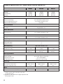
1
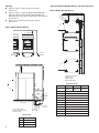
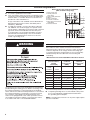
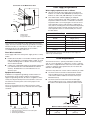
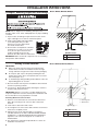
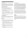
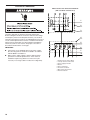
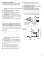
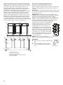
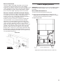
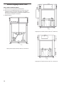
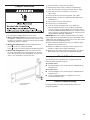
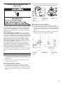
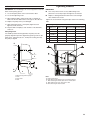
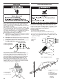
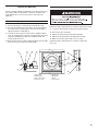
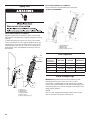
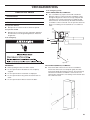
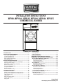
INSTALLATION INSTRUCTIONS
MFS80, MFS100, MFS125, MFS180, MFS230, MFS275
COMMERCIAL WASHER
TABLE OF CONTENTS
WASHER SAFETY ................................................................... 2
INSTALLATION REQUIREMENTS.......................................... 3
Tools, Parts, and Equipment.................................................. 3
Location Requirements ......................................................... 3
Electrical Requirements.......................................................... 6
Water Supply Requirements .................................................. 7
Drain Requirements ............................................................... 7
INSTALLATION INSTRUCTIONS ............................................ 8
Transport, Handling, Inspection, and Storage ....................... 8
Moving to Final Location ....................................................... 8
Water, Drain, and Venting Connections ................................. 9
Electrical Connection .......................................................... 10
R
emove Shipping Brackets ................................................. 13
Complete Installation ........................................................... 15
B
reak-In Period ................................................................... 15
Controls Troubleshooting .................................................... 15
WASHER MAINTENANCE .................................................... 16
Maintenance Schedule......................................................... 16
Vibration Switch Adjustment and Function Test.................. 17
Belt Inspection, Adjustment, and Replacement................... 18
Tightening Moments............................................................. 19
Lubrication........................................................................... 20
Water and Steam Filters...................................................... 20
Thrust of Door Seal.............................................................. 21
Spring Unit........................................................................... 22
Fuse Capacities......................................................................22
Earth Leakage Trips................................................................22
TROUBLESHOOTING..............................................................23
REMOVING THE WASHER FROM SERVICE.........................24
DIMENSIONS AND TECHNICAL SPECIFICATIONS..............25
Models MFS80, MFS100, and MFS125...............................25
Dimensions and Connections............................................26
Torque Specifications.........................................................26
Technical Specifications.....................................................27
Model MFS180......................................................................29
Dimensions and Connections............................................30
Torque Specifications.........................................................30
Models MFS230 and MFS275..............................................31
Dimensions and Connections............................................32
Torque Specifications.........................................................32
Technical Specifications
(Models MFS180, MFS230, and MFS275).........................33
Models MFS230 and MFS275
with Tilting Feature...............................................................35
Dimensions and Connections............................................35
Technical Specifications ....................................................35
W10214569B1
www.maytagcommerciallaundry.com
WASHER SAFETY
IMPORTANT:
■■
■■
■■
2
This washer must be directly wired to the electrical system
and may not be attached with a plug.
The circuit must be a dedicated circuit and may not be
combined with any lighting circuit.
Adequate grounding is essential to washer operation.
INSTALLATION REQUIREMENTS
Location Requirements
Tools, Parts, and Equipment
Read and follow the instructions provided with any tools listed
here.
Tools Needed
Washers must be installed by professional installers, who
should have a full compliment of standard SAE and metric hand
tools, and specialized tools as required. Gather the required
tools and parts before starting installation.
Washers must be installed on a level concrete floor on the
ground level of a building. Washers should not be installed on a
floor other than the ground floor, or in a room with a basement
or on a floor with rooms below without approval of a structural
engineer.
Proper installation is your responsibility and must meet all
governing codes and ordinances.
Working Conditions
Additional Materials
■■
Additional materials may be required for this type of installation
and the customer is responsible for supplying additional
hardware and adapters as necessary.
ashers should not be installed within reach of spraying
W
water.
■■
Do not install washer where it will be exposed to weather or
excessive humidity. Do not allow water or condensation to
run over walls or floor under washer. Ambient temperature
for storage or transportation must be between -13 and 131°F
(-25 and 55°C).
Parts Supplied
Remove parts bag from washer drum. Check that all parts were
included. The number of parts supplied varies with model.
■■ Molded rubber drain hose and band clamp (2 each)
■■ Rubber washers for the hoses (4)
■■ Water supply hoses (2)
Equipment for Handling, Transport, and Storage
Floor
Space requirements for installations are determined by
the number of washers being installed. See “Technical
Specifications” and “Installation Instructions” for more detailed
information.
■■
Use a lift truck or a manual skid cart for handling the washer
when it still is in the packaging material.
■■
The lift truck forks must be at least 4" (100 mm) longer
than the length of the washer frame.
Installation must be on a solid concrete floor or slab capable
of withstanding the weight and vibration produced by the
washer. The maximum slope of the floor is 1° under the
washer. A rough, uncovered concrete surface is preferable
to a smooth or covered surface.
Weight of Washers
Weight on
floor
80 lbs
33 kg
100 lbs
40 kg
125 lbs
55 kg
180 lbs
80 kg
230 lbs
104 kg
275 lbs
125 kg
Maximum
static load
3239 lbs
1469 kg
4083 lbs
1852 kg
4400 lbs
1996 kg
7144 lbs
3241 kg
–
–
Maximum
dynamic
load (alt.
2855 lbs
1295 kg
+616 lbs
+279 kg
3615 lbs
1640 kg
+661 lbs
+300 kg
3835 lbs
1740 kg
+704 lbs
+319 kg
6176 lbs
2801 kg
+1511 lbs
+685 kg
–
–
Dynamic
load
frequency
14.0 Hz
14.0 Hz
14.0 Hz
12.5 Hz
–
–
(with linen and
water)
stress when
extracting)
X - fork length
X
Fork
Length
■■
■■
Required Fork Length Chart
80 lbs/100 lbs/125 lbs 180 lbs
230 lbs/275 lbs
(33 kg/40 kg/55 kg)
(80 kg)
(104 kg/125 kg)
59"
1500 mm
71"
1800 mm
79" 2000 mm
■■
Washer must be secured with four (4) M16 x 160 mm
anchoring bolts. Install all four anchors before final
installation of the washer. Apply a torque of 210 Nm/
155 ft. lbs.
■■
Washer will be firmly secured to the floor and all four (4)
footings must touch the floor.
■■
Allow for adequate sanitary sewer drainage, located
behind the washers.
If possible, leave the washer in the packaging or on wooden
skid until foundation is prepared for installation. Washer is
attached to skid by four (4) M-16 bolts.
Water and Electric
See “Moving to Final Location” for more information on
moving washer to its final location.
■■
A hot water heater set at 158°F (70°C).
■■
1" (25 mm) inlet valves for hot and cold water. Determine
water hardness levels. Hard or medium levels may require
a water softener.
■■
A dedicated, GFCI-equipped circuit for each washer
(see “Electrical Requirements”).
3
Spacing
Spacing Between Multiple Washers and Feet Placement
■■
Washers require 2.4 ft (0.7 m) above the top for
maintenance.
■■
Washers require 2.4 ft (0.7 m) (Models MFS80/MFS100/
MFS125) and 2.6 ft (0.8 m) (Models MFS180/MFS230/
MFS275) between the sides for maintenance and maximum
door clearance.
X4
1
2
X12
Allow 3.3 ft (1 m) behind washer and the wall for
maintenance.
3
X13
■■
Models MFS80, MFS100, MFS125
Models MFS80, MFS100, MFS125
4
X6
X15
X1
X2
X14
X5 700 mm 28"
2.3 ft
28"
(711
mm)
(0.7
m)
2.3 ft
(0.7
P m)
2.3 ft
(0.7 m)P
X16
700 mm
28"
Front View
X17
1. Washer contour line
2. Washer foot
3. Waste sump
4. Drain with elbow
Feet Placement
40"
1000 mm
X3
X11
Side View
X10
1. Drain with elbow
2. Cover of waste pump
3. Waste sump
X9
Dimensions
X3 46.25" (1175 mm)
X9
14" (350 mm)
X10
12" (300 mm)
X11
9" (250 mm)
4
1
2
3
DistanceMS80 MS100 MS125
X1 38.19"42.13"49.21"
(970 mm) (1070 mm) (1250 mm)
Distance
All Models
X2
36.61" (930 mm)
X4 32.7" (830 mm)
X5
5.12" (130 mm)
X6
3.03" (77 mm)
X12
8" (200 mm)
X13
9" (250 mm)
X14
29.5" (750 mm)
X15
6" (150 mm)
X16
7" (180 mm)
X17
8" (200 mm)
Models MFS180, MFS230, MFS275
Spacing Between Multiple Washers and Feet Placement
Models MFS180, MFS230, MFS275
2.3 ft
28"
(711
mm)
(0.7
m)
2.6 ft
(0.8
P m)
2.6 ft
(0.8 m)P
Front View
X1
X2
1
2
SideView
View
Side
1. Drain hose
2. Waste sump cover
3. Waste sump
3
X3
Dimensions
X1
X2
X3
X13
27.55" (700 mm)
39.36" (1000 mm)
16.33" (415 mm)
9.84" (250 mm)
1. Washer contour line
2. Washer foot
3. Waste sump
4. Drain hose
Feet Placement
DistanceMS180MS230MS275
X1 49.99"54.64"55.11"
(1270 mm) (1388 mm) (1400 mm)
X2 56.29"67.51"70.07"
(1430 mm) (1715 mm) (1780 mm)
X3 41.92" 52.44" 52.44""
(1065 mm) (1332 mm) (1332 mm)
X4 30.70"30.70"30.70"
(780 mm) (780 mm) (780 mm)
X5 0.78"0.53"0.59"
(20 mm) (13.50 mm) (15 mm)
X6
5.9" 5.11" 5.19"
(150 mm) (130 mm) (132 mm)
X19 27.55"31.49"31.49"
(700 mm) (800 mm) (800 mm)
Product Dimensions
See “Technical Specifications” for specific measurements on
each washer size.
5
Electrical Requirements
Washer Connection to Electrical Network
(With an Earth Leakage Trip)
It Is Your Responsibility:
■■
■■
■■
To contact a qualified electrical installer.
To be sure that the electrical connection is adequate and in
conformance with the National Electrical Code, ANSI/NFPA
70-latest edition, or Canadian Electrical Code CSA C22.1,
and all local codes and ordinances.
A copy of the above code standards can be obtained from:
National Fire Protection Association, One Batterymarch
Park,Quincy, MA 02269.
To supply the required 3 or 4 wire, three-phase, 208–240
volt, 50/60 Hz., AC electrical supply on a separate circuit.
Circuit capacity is dependent on washer size and connection
type and is shown in the table below. A time-delay fuse
or circuit breaker is recommended. Installation of a GFCI
(Ground Fault Circuit Interrupter) is also recommended.
Connect to an individual branch circuit. Do not fuse the
neutral or grounding circuit.
1. Earth leakage trip
2. Laundry electrical
main switch
3. Power supply protection
4. Washer
5. Phase conductors
6. Protective conductor
7. Main switch inlet terminal
switchboard
8. Neutral conductor
1
2
3
4
5
6
7
8
Electrical Connection
WARNING
Inlet Conductors and Power Supply Protection
Inlet conductors of the washer connection to the electrical
network must have copper cores. The cross section of the inlet
conductors depends on the voltage and the unit heating type,
i.e. total electrical input. Circuit breakers or fuses in the laundry
switchboard keep the inlet cable from short-circuiting and
overloading.
Manufacturer’s Recommended Minimal Conductor Section
Power supply
protection device
nominal
current (US)
The electrical connections were designed per the specifications
provided during the ordering process. Before connecting, verify
the voltage and frequency on the washer label. See the Back
View in “Dimensions and Technical Specifications” to ensure that
the voltage and frequency correspond to your power network.
The connection is described in the illustration below. If the
washer is not equipped with a main switch, power disconnects
are needed for all electrical supplies connected to the washer,
in accordance with item 5.3 in standard EN 60204-1.
6
Min. phase
conductor
section in mm2
(AWG)
Min. protective
conductor
section in mm2
(AWG)
Automatic
circuit
breakers
Fuses
16A (15A)
10A (10A)
1.5 mm2 (AWG 15) 1.5 mm2 (AWG 15)
20A (20A)
16A (15A)
2.5 mm2 (AWG 13) 2.5 mm2 (AWG 13)
25A (–)
20A (20A)
4 mm2 (AWG 11)
4 mm2 (AWG 11)
40A (40A)
32A (30A)
6 mm (AWG 9)
6 mm2 (AWG 9)
63A (–)
50A (50A)
10 mm2 (AWG 7)
10 mm2 (AWG 7)
80A
2
63A
2
16 mm
16 mm2
100A
80A
25 mm2
16 mm2
125A
100A
35 mm2
25 mm2
See “Technical Specifications” for the corresponding current.
■■
A separate grounding wire is recommended if codes permit.
It is recommended that a qualified electrician determine
the grounding path is adequate.
NOTE: Connecting these washers to an IT power supply requires
special consideration.
Connection of the Main Power Inlet
Water Supply Requirements
Water supply requirements are as follows:
1
■■
Valved hot and cold water supply with a water pressure
between 14.5 and 116 PSI (100–800 kPa). Water pressure
between 43 and 73 PSI (300–500 kPa) is recommended.
■■
A hot water heater or boiler supplying an adequate
amount of water between 120–160°F (49–80°C). The water
temperature within the washer is controlled to a maximum
temperature that is set in the program. The amount of hot
water required to wash a load of laundry is dependent on
many factors, including the hot and cold water temperature
and the wash program selected. Average amounts of hot
water required to wash one load of laundry are shown in
the table below.
2
3
Hot Water Requirement Per Load
1. Main switch
2. Strain relief
3. Sag of inlet cable
Connection to Washer
These washers were designed for direct wiring into the power
supply. The washer must be electrically grounded in accordance
with all local codes or, in the absence of local codes, with the
National Electrical Code, ANSI/NFPA 70, latest edition,
or Canadian Electrical Code, CSA C22.1.
Direct Wire Installation:
Power supply cable must match power supply (4-wire or 3-wire)
and be:
■■
■■
Flexible armored cable or nonmetallic sheathed copper cable
(with grounding wire), in a flexible metallic conduit, to avoid
conductor breakage due to vibration. All current-carrying
wires must be insulated.
Copper wire of appropriate gauge for amperage requirement
(see “Manufacturer’s Recommended Minimal Conductor
Section”). Stranded wire is recommended. Do not use
aluminum wire.
Washer Model
Hot water per load*
MFS80
60 gal. (227 L)
MFS100
70 gal. (265 L)
MFS125
80 gal. (303 L)
MFS180
–
MFS230
–
MFS275
–
*Approximate values. Assumes 140°F (60°C) hot water supply and
70°F (21°C) cold water supply.
Drain Requirements
The washers have two 3" (76 mm) water drains on their rear
side. To connect the drains to a drain hose, use the 3" (76 mm)
elbow which is supplied with the washer. Secure the elbow with
a clamp. To maintain washer performance, do not reduce the
diameter of the drain pipe.
The washer may drain into a waste channel or directly to a drain.
Equipotential bonding:
■■
In addition to an equipment-grounding conductor that must
be run with the circuit conductor and be connected to the
equipment grounding terminal, all washers or appliances in the
vicinity must be permanently interconnected with a connector.
The waste channel cannot be located under the washer.
There should be at least 4" (102 mm) between the back
of the washer and the middle of the waste channel (see
illustration below).
■■
The waste channel must be lower than the drain pipe.
There should be at least a 3/4" (19 mm) air gap between
the bottom of the drain and the water level in the channel.
The external connection points serve for this purpose. See
illustration below.
The cross-sectional area of the conductor must be at least
electrically equivalent to the cross-sectional area of the copper
conductor.
3
3
4
3
X
2
4"
(102 mm)
3
1.
2.
3.
4.
1
Protective grounding structure
External protective conductor connection point
Protective conductor
Grounding identification
3/4"
(19 mm)
Minimum Waste Channel Measurements
X
MFS80/100/125
MFS180/230/275
4"
(102 mm)
4"
(102 mm)
7
INSTALLATION INSTRUCTIONS
Transport, Handling, Inspection, and Storage
Models MFS80, MFS100, MFS125
4
2
NOTE: Refer to "Equipment for Handling, Transport, and
Storage" under "Tools, Parts, and Equipment" for proper handling
of washer.
1. Inspect carton for damage. Inspect washer if carton shows
signs of damage. Do not remove washer from pallet.
2. Verify model number and serial number
on the data plate with your order.
Remove accessories and manuals
from inside washer drum.
3. Store inside in a temperature controlled
environment -13° and 131°F (-25° and
55°C). Do not expose washer to the
weather. Humidity levels must be
Data Plate
between 30 to 90% without condensation.
IMPORTANT: Make sure that all components are secured during
transportation and installation.
Moving to Final Location
IMPORTANT:
■■ Make sure all passages and spaces through which the
washer will be moved to its installation location are high
enough and wide enough for the washer and its packaging.
■■
Do not push, pull, or press the parts protruding from the
washer (front section, door, control panel, belt cover, water
inlet, outlet pipes, etc.).
■■
To avoid damage during handling and installation, make sure
all protruding parts are secured.
2 - Washer foot
4- Anchoring bolt
Bolt Dimensions
X7
X8
1.57" (40 mm)
5.9" (150 mm)
Models MFS180, MFS230, MFS275
1
2
1. M
ove the washer near the point of installation with a lift truck
and remove packing material.
2. Loosen the 4 - M16 x 160 mm bolts attaching the washer to
the pallet and gently lift washer.
IMPORTANT: Washer is very heavy. Consider equipment and
manpower required to move this washer prior to installation and
be sure that all necessary preparations are made.
X8
Fastening Washer to Concrete Floor
1. W
asher is to be attached to the concrete floor with anchor
bolts. All four footings must come into firm contact with
the floor.
2. Level washer’s base frame with a level.
3. D
o not tighten nuts of the anchor bolts until the concrete floor
or base has completely cured.
4. Tighten the nuts of the anchoring bolts to a maximum
155 lbf.ft/210 Nm for the bolts on Models MFS80, MFS100,
and MFS125. For Models MFS180, MFS230, and MFS275
tighten the nuts of the anchoring bolts to a maximum of
36 lbf.ft/49 Nm.
5. See “Dimensions and Technical Specifications” section for
installation measurements.
8
X7
Bolt Dimensions
X7
X8
2.36" (60 mm)
6.3" (160 mm)
1- Anchoring bolt
2 - Washer foot
Water, Drain, and Venting Connections
Water Hardness
Drain Connections
Determine the water hardness level in water supply. Good wash
results are dependent on water hardness. In areas that have
medium and very hard water levels, a water softener may be
required. Contact your water or soap distributor for determining
the proper soap and detergents to be used with your hardness
levels for the best wash results.
1. Always use the flexible hoses delivered with the washer.
Do not use a fixed connection to the water supply.
MFS80, MFS100, and MFS125 washers are equipped with
two 3" (75 mm) diameter drain pipes. MFS180, MFS230, and
MFS275 washers are equipped with two 4" (100 mm) diameter
drain pipes. See “Dimensions and Technical Specifications” for
location. Both pipes must be connected to the waste sump.
The sump must be positioned lower than the drain, because the
washer uses gravity to discharge water. Use the provided drain
hose to connect drain pipes to sump. Secure with a clamp and
properly cover sump. The capacity of discharged water for each
washer model is 300.00 dm3/min and 80.00 gal/min for the 3"
drain. For the 4" drains, the capacity of discharged water for
each washer model is 540.00 dm3/min and 142.00 gal/min.
2. Keep proper water pressure within range. See “Dimensions
and Technical Specifications.”
Recycled Water Drain Connection (some models)
Water Supply Connections
Washers have 2 water inlets. For connection dimensions,
see “Dimensions and Technical Specifications.”
3.Connect all water inlets to a water supply. Contact your dealer
if there is no hot water supply available.
4. 1" (25 mm) or 1.5" (38 mm) Inlet valves for hot and cold water
use inlet pressure hoses with gaskets. Mount shut-off valves
to the water supply pipes for cleaning filters and performing
maintenance.
5. To connect the washer to the water inlet shut-off valves,
use the provided flexible hoses.
Steam Connections
Washer with steam heating is equipped with an outer thread
in the back of the washer for connection with the washer steam
line. See “Dimensions and Technical Specifications” for more
details.
IMPORTANT:
■■ Install a steam supply disconnecting device near each
washer.
■■
Inlet value of steam pressure must be within range. Any
other pressure may result in washer not functioning properly.
■■
To avoid possible injuries, shut off the main steam inlet and
let the parts cool down after connection.
■■
Insert a filter with permeability up to 300 micrometers in
front of every steam valve. Dirt particles larger than 300
micrometers can damage the steam valve and cause
leakage.
■■
Attach steam filter to the washer at the connection point.
The supply piping must be clean without dirt and rust
particles. Impurities in the supply line can cause steam
valves to fail.
■■
Do not twist the filter gasket when connecting the pipes.
To shut off the assembly, clamp the filter at the side of the
connecting pipe.
Attach connecting hoses to the discharging valve located on
the right side (from rear view). The hoses go to your recycling
tank located below the drainage valve. The tank must be large
enough for the total weight and volume of water and made up of
materials which withstand 176°F (80°C) and the effects of laundry
soap. The quantity of water will vary by washer size and cycle.
Venting
IMPORTANT: To maintain proper venting, do not cover the
washer vent.
Although not recommended, it is possible to connect vent to the
laundry central exhaust ducts. Venting materials must withstand
a temperature of 176°F (80°C). Always use flexible vent material
if a connection is made. The central vent for multiple washers
must be dimensioned for the total cross section of all vents and
washers. Calibrate washer’s “zero” level after vent has been
attached.
9
Electrical Connection
Washer Connection to Electrical Network
(with a residual current device)
1
2
3
Check the data plate to determine electrical requirements.
Before making the electrical connection, make sure the voltage
and frequency listed on the data plate matches your electrical
network. Each washer must be on an individual branch circuit. To
ensure uninterrupted electrical current, a residual current device
(RCD) and a circuit breaker must be installed in the building’s
electrical system for each washer. The proper connection is
described in the illustration on the right.
4
5
6
IMPORTANT:
■■ If the washer is not equipped with a main switch, supply
disconnecting devices need to be installed in accordance
with EN 60204-1 standard 5.3.
■■
10
Make sure the supply voltage is always within the limits
specified in “Technical Specifications.” If the electrical
installation requires long distances to travel, it may be
necessary to use larger cables to reduce the voltage drop.
7
8
1. Residual current device (RCD)
2. Laundry electrical main switch
3. Power supply protection
4. Washer
5. Phase conductors
6. Protective conductor
7. Main switch inlet terminal
8. Neutral conductor
Residual Current Device (RCD)
■■
In some countries an RCD is known as an “earth leakage trip,”
“Ground Fault Circuit Interrupter” (GFCI), “Appliance Leakage
Current Interrupter” (ALCI), or “earth (ground) leakage current
breaker.”
Specifications:
■■ Tripping current: 100mA (if locally not available/allowed use
a 30mA trip current, preferably selective type with small time
delay set).
With stranded conductors, it is recommended to use
“wire-end tubes” with an insulated sleeve (6) for L1/U,
(L2/V), (L3/W), (N) conductors. Make sure there cannot be
unintentional contact, since the supply cable stays under
voltage even when the main switch is off.
■■
Crimp a ring terminal (eyelet) to the protective conductor for
good connection to the PE terminal.
■■
Connect the supply cable conductors to the terminals
(main switch [1]) marked with L1/U, (L2/V), (L3/W), (N),
and the terminal (copper screw) marked with PE.
See “Main Power Inlet Connection” illustration below.
■■
Provide a sag in the cable, in front of the cable strain relief.
This will stop condensed water from entering the washer.
See “Main Power Inlet Connection” illustration below.
■■
Install a maximum of two (2) washers on each RCD
(for 30mA, only one (1) washer)
■■
ype B. There are components inside the washer which use
T
DC-voltages, making a “Type B” RCD necessary.
N
OTE: Type B performs better than Type A, and Type A is
better than Type AC.
Adaptation of Conductor Ends of Supply Cable
When locally allowed, an RCD must always be installed. In some
electrical network earthing systems (IT, TN-C,…), an RCD might
not be allowed (see also IEC 60364).
The washer control circuits are mostly supplied by a separating
transformer. Therefore, the RCD may not detect faults in the
control circuits (but the fuse(s) of the separating transformer will).
Supply Protection Device
A supply protection device keeps the washer and wiring from
experiencing overloads and short circuits. As a supply protection
device, you can use either glow-wire fuses or automatic circuit
breakers. See “Technical Specifications” for the rating of the
nominal current and other specifications of the supply protection
device. This table specifies that protection must be the “slow”
type, curve D for circuit breakers. Although not recommended,
if you cannot use a “slow” type, select the protection device with
one (1) step higher nominal current rating to avoid disconnecting
during start-up.
Supply Cable
The supply cable is not delivered with the washer.
Specifications:
■■ Use conductors with copper cores.
■■
Stranded conductors (flexible wiring) are strongly
recommended to avoid conductor breaking due to vibration.
■■
The cross section depends on the used supply protection
device. See “Manufacturer’s Recommended Minimal
Conductor Section” in “Electrical Requirements” for the
minimal cross section.
■■
The cable should be as short as possible, directly across
from the supply protection device to the washer without
branching off.
■■
Do not use a plug or extension cords; the washer is intended
to be permanently connected to the electrical network.
1. Protective conductor
2. Phase conductor
3. Phase conductor
4. Phase conductor
5. Neutral conductor
6. Wire-end tube
7. The stripped length of
conductors
Main Power Inlet Connection
1. Main switch
2. Strain relief
3. Sag of inlet cable
1
2
3
Connection:
■■ Insert the cable through the hole on the rear panel.
Use a strain relief to secure the supply cable.
■■
Strip the conductor ends according to “Adaptation of
Conductor Ends of Supply Cable” illustration on the right.
■■
The protective conductor must be longer to ensure it
is the last one disconnected if the cable is pulled out
unintentionally.
11
Washer Earth Connection and Equipotential Bonding
Connecting Liquid Soap Supply Systems
Independent of the supply cable, the washer must be connected
to the laundry earth system with a separate conductor. The
protective conductor, which enables this connection, is not
included with the washer. If there are other washers/appliances
with exposed conductive parts which can be touched
simultaneously, make equipotential bonding between all of these
appliances. The external terminal for this purpose is located
on the rear panel of the washer frame (see illustration below,
position 3). The minimum protective conductor’s cross section
depends on the supply cable cross section and can be found
in “Manufacturer’s Recommended Minimal Conductor Section”
in “Electrical Requirements.” However, to keep a supply cable
section of a minimum 4 mm2 from malfunction , it is recommended
to select a larger conductor section, for example 6 mm2.
All models come with a liquid soap connection.
Always use liquid soap pumps that have a flow rate high enough
to bring the desired quantity into the washer in less than 30
seconds.
IMPORTANT: Start pumping immediately after the water valves
are open. The incoming water dilutes the liquid soap and brings it
into the tub assembly.
IMPORTANT: Only qualified technicians should perform the
installation. Secure the location of the wiring and hoses properly
to keep them from being pinched, damaged, or rubbed.
Before you start to use liquid soap, check with your liquid soap
supplier to ensure the liquid soap will not cause damage and
is inert to HD-PE and PVC material. The manufacturer is not
responsible for damage caused by the liquid soap.
The washer has connections for external dosing
of liquid soaps. A plastic hose connection is
located on the rear of the washer to connect
the liquid soap hoses. The connection has
six (6) nipples that come closed at the factory.
You must drill a 0.315"/8 mm hole in the small
nipple for each liquid soap connection used (5
maximum). A ½"/12 mm nipple is also located
on the plastic hose connection. Use this nipple
ONLY for pumping in diluted soap. If you need
to use the large nipple, you must drill a 0.45"/
11.5 mm hole into it.
Models MFS80/
NOTE: Gently remove the drill particles so
100/125/180
that they cannot clog up the hoses and openings.
3
3
3
3
5
3
3
1
2
4
3
3
3
4
4
4
3
3
5
4
3
IMPORTANT:
■■ Make sure hose connections and clamps are
tight.
1
■■
2
4
4
1. Washer (rear view)
2. Laundry earth connection
3. Washer external terminal
4. Protective conductor – washer connection
5. Earth ground label
12
If one of the nipples is open, close and
secure the opening with an appropriate
cover.
Models
MFS230/275
Electrical Connection
Remove Shipping Brackets
The power supply of the liquid soap pump system must be
connected to an external electrical source. Only qualified
technicians can make the electrical connection according to local
codes. Instructions for the correct connection can be found on
the wiring diagram located in a plastic bag inside the cabinet.
Do not connect the liquid soap pump system in the washer.
IMPORTANT: Shipping brackets must be removed before putting
the washer into service. Failure to do so can cause damage to
the washer.
Electronic Controller with MC5 and Graphic Display
1. Remove the front lower panel and rear panel.
For electrical connection of supply control signals, a plastic box
is located on the rear of the washer (see illustration below,
position 1). There is also a terminal box with LED signalization
of activation of the respective pump (position 2).
A label for electrical connections is located on the back side
of the terminal box cover (see illustration below). Detailed
information on connecting signals can also be found on the
electric schematic of the washer. Signals for the supply pump
control are 24V AC. Maximum current for control circuits of
pumps must be limited to 10mA. Insert the cable for connection
of pump control signals through the plastic cable strain relief
(position 3). After connection of conductors to the respective
positions of the connector “P” (screw clamps), attach the cable
by tightening the cable strain relief and replace the cover on the
box. For details about liquid soap supply system programming,
see the programming manual.
2. Remove
the front shipping bracket (1) and the two rear
shipping brackets (2). Retain brackets and bolts if needed to
secure the washer for transport in the future.
Models MFS80, MFS100, MFS125
3. Replace both panels.
Rear Panel
Electrical connection label
1
1
2
Side View of Brackets (2)
2
3
Shipping Brackets (Models MFS80, MFS100, and MFS125)
13
Remove Shipping Brackets (cont.)
Models MFS180, MFS230, MFS275
1. Remove the rear lower panel and side panels.
2. Remove
the rear shipping bracket (1), the three left-side
shipping brackets (2), and the three right-side shipping
brackets (3). Retain brackets and bolts if needed to secure
the washer for transport in the future.
3. Replace panels.
Left-Side View of Brackets (3)
Shipping Brackets (Models MFS180, MFS230, and MFS275)
Rear View of Bracket (1)
Shipping Bracket (Models MFS180, MFS230, and MFS275)
3
Right-Side View of Brackets (3)
Shipping Brackets (Models MFS180, MFS230, and MFS275)
14
5. Remove the film covering from the cabinet.
Complete Installation
6. Make sure the waste sump is ready for water drainage.
7. Open door and make sure that the washer drum is empty.
8. Verify
that washer is level and does not rock from
side-to-side.
9. Check electrical connection and ground – PE or PEN.
10. A
djust vibration switch. See “Vibration Switch Adjustment”
in Maintenance.
11. Check drain connection and clearance.
12. Turn power on at circuit breaker.
13. T
urn the washer on. Begin a wash cycle. Watch the
drum during the extraction cycle. The drum should rotate
counter-clockwise as observed from the front of the washer
for Models MFS80, MFS100, and MFS125. The drum should
rotate clockwise as observed from the front of the washer for
Models MFS180, MFS230, and MFS275.
1. Be sure that the shipping brackets are removed.
2. M
odels with Tilting Feature: Remove the braces securing
the vibration components for transport. Then, in those same
locations, mount the two stops that secure the tub assembly
during tiliting. Replace all panels.
3. M
odels with Tilting Feature: Check the tilting direction.
Press
on remote control to tilt forward.
P
ress
on remote control to tilt back to beginning position.
4. M
odels with Tilting Feature: Make sure the Door Latch
(2) can be inserted into the Latch Receptacle (1). The Door
Latch will keep the door open during tilting. To release the
door to close it, pull down on the Door Latch.
IMPORTANT: If the drum rotates counterclockwise, turn off the
power supply at the circuit breaker and reverse the polarity of the
supply wires from the frequency inverter to the motor. This should
only be performed by qualified personnel.
14. Perform vibration switch function test (see “Vibration Switch
Adjustment and Function Test”).
15. Initialize for calibration of zero level (on the microprocessor
model) according to the Programming Manual.
16. Begin wash cycle again. Activate the emergency stop switch.
All electrical power to the washer should be deactivated.
Break-In Period
The following checks and adjustments should be performed
during the break-in period as follows:
24 operation hours
■■
Check belt tightness. See “Belt Inspection and Adjustment”
in Maintenance.
80 operation hours
2
1
1. Latch Receptacle
2. Door Latch
■■
Check belt tightness. See “Belt Inspection and Adjustment”
in Maintenance.
■■
Check mounting bolt tightness. Retighten if necessary
(secured installation only).
Controls Troubleshooting
For programming and controls troubleshooting, refer to the
Programming Guide.
15
WASHER MAINTENANCE
Maintenance Schedule
After Each Load
■■
Remove debris from the wash drum including paper clips,
coins, and other hard items.
■■
When not in use, leave the washer door open to allow the
washer to air out and prolong gasket life.
Daily Maintenance
■■
Clean water, detergent, and other stains off of the washer
with a soft cloth dampened with a mild detergent solution.
■■
Dry with a soft cloth. Do not use abrasives.
■■
Clean detergent residue and other contamination off the door
seal with a soft cloth dampened only with a mild detergent
solution. Do not use solvents or acids. Do not lubricate seal
with oil or grease.
■■
Remove residue from the laundry product hoppers with
a plastic scraper. Wipe the hoppers with a soft cloth
dampened with water.
■■
Check water and steam inlets for leaks. Correct as
necessary.
■■
Check drain valve for leakage during a wash cycle (the valve
is in open position when there is no electricity to it).
Maintenance Every 200 Working Hours or Every
Month
1. Lubricate according to “Lubrication” section.
2. M
ake sure external liquid soap supply system is not leaking.
Check all hose joints, screw joints and all connections in the
system.
Maintenance Every 500 Working Hours or 3 Months
■■
Observe the washer from the back for one wash cycle.
Be sure that water does not leak out of the drain during
the wash part of the cycle and that it drains freely at the
beginning of extraction. Clean the drain if either of these
symptoms are observed.
1. Turn off power to washer at the circuit breaker or fuse box.
16
2. C
heck the tightness of the bolts securing the rear panel
of the washer.
3. Inspect all hoses and connections inside the washer for
leaks and correct as necessary.
4. W
ipe off any stains with a soft cloth dampened with water
or a mild detergent solution. Be sure that control components
are not exposed to dust and moisture during cleaning.
5. L
ubricate bearings and seals with a grease gun.
See “Lubrication” section.
6. T
ighten the contacts of heating element terminals on models
with electric heating elements.
7. P
ut covers back on and check that all bolts are properly
torqued.
8. Turn on power at circuit breaker or fuse box.
Maintenance Every 1000 Working Hours or 6 Months
■■
Turn off hot and cold water to the washer at the valves.
Clean water filters.
■■
Clean and remove dirt and dust from:
– the inverter cooling fin
– the motor cooling fins
– the inverter internal fan (if present)
– the external fan (if present)
– the external air relieves.
■■
Make sure the fan in the inverter cool fins (if present) is
functioning.
■■
Make sure the external fan (if present) is functioning.
■■
Remove the rear cover. Inspect the V-belts and tension.
See “Belt Inspection, Adjustment, and Replacement.”
■■
Check mounting bolt tightness. Retighten if necessary
(fixed installation only).
Maintenance Every 2000 Working Hours
or 12 Months
■■
Adjust and perform functional test on vibration switch
(see “Vibration Switch Adjustment and Function Testing”).
Vibration Switch Adjustment and
Function Test
5. M
oving the holder (7) with the switch left or right will center
the switch control element in the limiter’s rubber bushing.
C
5
B
3
5
2
6
A
1
7
2
4
4
1
Front view
Side view
1. Front face
of the drum
2. Limiter
3. Rubber bushing
4. Mounting plate
5. Vibration switch
6. Adjusting nut
7. Vibration switch
holder
Models MFS180, MFS230, and MFS275:
The Vibration Switch is a critical component of the washer that
avoids washer damage during extraction with an unbalanced
load. Vibration Switch adjustment must be performed during
installation and checked annually, and should only be done by a
qualified technician.
Models MFS80, MFS100, and MFS125: The Vibration Switch is
on an assembly bolted to the bottom of the mounting plate (4).
The switch controlling element is inserted into the rubber bushing
(3) located in the limiter (2). The limiter is bolted to the drum front
face (1). The switch attached to the mounting plate is a part
of the washer frame, which is attached to the limiter with the
bushing. The bushing is the part of the assembly that vibrates.
4. B
y moving the vibration switch on the holder to the left,
you will decrease the sensitivity; to the right, you increase it.
It is necessary to keep the distance of 2.36" (60 mm) between
the limiter (2) and the vibration switch (4). See the Side View
below.
5. M
oving the holder (6) with the switch left or right will center
the switch control element between the limiters.
1
B
Models MFS180, MFS230, and MFS275: The vibration switch
has a flexible controlling element. The element is attached to
a holder (6) by nuts (5). The entire assembly is bolted to the
washer frame (3). The switch controlling element is inserted into
the limiters (2), which are bolted to the drum front face (1). The
limiters are the part of the assembly that vibrate.
For all models, the bushing adjusts the sensitivity of the vibration
switch by controlling the unbalance level of the wash load in the
drum.
Vibration Switch Adjustment
2
4
6
3
Front view
Side view
1. Front face
of the drum
2. Limiters
3. Washer frame
4. Vibration switch
5. Adjusting nut
6. Vibration switch
holder
1. If the washer was just installed, run the washer through one
complete extraction cycle without a load so the drum is at its
balance point.
2. Turn off power to washer at the circuit breaker or fuse box.
3. Open the control panel cover.
Models MFS80, MFS100, and MFS125:
4. B
y moving the vibration switch on the holder to the left,
you will increase the sensitivity; to the right, you decrease it.
It is necessary to keep the distance of 4" (100 mm) between
the limiter (2) and the vibration switch (5). See the Side View
below.
17
Verifying the Vibration Switch Function
Belt Inspection and Adjustment
1. Open the control panel cover.
1. Turn off power to washer at the circuit breaker or fuse box.
2. Start the extraction mode.
2. T
he belts are accessible after the rear or side cover has been
removed. Check the belts to make sure they are neither too
tight or too loose. Change the belts if they are worn out or
damaged. Always change a complete set of the belts for one
transmission with the same type of belts being removed.
3. A
fter reaching maximum RPM, switch over the vibration
switch by moving the flexible control element manually.
The extraction cycle should stop. If extraction does not
stop, the vibration switch requires adjustment or is defective.
Belt Inspection, Adjustment,
and Replacement
On a new washer or after a belt replacement, make an inspection
of the belt tightness:
1. After the first 24 hours of operation;
2. After the first 80 hours of operation; and,
3. E
very 6 months or 100 hours of operation, whichever
comes first.
18
3. B
e sure that the belt pulleys are aligned by laying a straight
edge along the pulley faces. If all points are touching the
straight edge, the pulleys are aligned.
4. C
hecking the belt tension requires a straight edge and a belt
tension gauge. Place the straight edge from the drum pulley
to the motor pulley. Belt tension is correct for Model MFS80
when a 12.1 lb (5.5 kg) force applied to the midpoint of the
belt between the two pulleys deflects the belt 4/5" (20 mm).
Belt tension is correct for Models MFS100 and MFS125
when a 15.4 lb (7 kg) force applied to the midpoint of the
belt between the two pulleys deflects the belt 4/5" (20 mm).
Belt tension is correct for Model MFS180 when a 2.6 lb
(1.2 kg) force applied to the midpoint of the belt between
the two pulleys deflects the belt 1/2" (12.3 mm). Belt tension
is correct for Models MFS230 and MFS275 when a 4.9 lb
(2.2 kg) force applied to the midpoint of the belt between
the two pulleys deflects the belt 0.35" (9 mm). To adjust the
belt, first loosen the locking nut and loosen or tighten the belt
as necessary. Retighten the locking nut when adjusted and
recheck.
5. R
eplace rear panel of washer. Turn on power at circuit breaker
or fuse box.
Tightening Moments
Belt Replacement
1. Loosen the pulley bolts on the rear wall of the drum.
IMPORTANT:
■■ Once every three months or every 500 working hours
(whichever comes first) inspect the tightness of the bolts.
2. L
oosen the adjusting screw.
■■
IMPORTANT: To avoid damage, do not use a pry bar to force the
belts over the pulley grooves.
3. W
hen replacing belts, replace them with a complete set.
Make sure the new belts are the same type as the old ones.
4. Replace the pulleys if they are damaged.
5. A
fter replacing the belts, check pulley alignment, belt
tightness, bolts, and nuts.
6. K
eep the belts and pulleys clean and free of oil, lubricants,
water, etc.
Pulley Alignment:
For reliable operation and long belt life, the pulley must be
properly aligned. Inspect the alignment by placing a ruler on the
pulley faces. If all points (A, B, C, and D) are touching the ruler,
the pulley is aligned.
Tighten the loosened bolts using the torque value in the following
table:
Tightening Moments Values of Bolts and Nuts
Bolt
Tightening
Tightening
(nut) Dimension Number of Pcs. Moments (Nm) Moments (lbf.ft)
A
M20 x 65
24 (12)
600.00
B
M12 x 30
8
70.00
52.00
33 kg TYPE: nut KM13
1
450.00
332.00
C
M12 x 35
6
70.00
52.00
D
M30 x 80
1
800.00
590.00
E
M12 x 38
4
25.00
18.50
D
443.00
1
C
2
B
A
Replace a damaged bolt with a bolt of the same strength
value marked on its head.
4
3
1. Main housing with the pulley
2. Drum
3. Drive motor
4. Ruler
Bolts:
A. Bolts of hub flange
B. Bolts attaching the pulley to the nut of fixing housing
C. Bolts attaching the motors plate to the external drum
D. Bolts attaching the inner drum to the shaft
E. Bolts attaching the door brackets
19
Water and Steam Filters
Lubrication
WARNING
Grease bearings and seals with a grease gun slowly, not faster
than 5 strokes per minute. This avoids seal deformation and
leakage. Do not operate the grease gun faster, even if the
grease contains air gaps. Too much lubrication can cause the
same damage as too little.
Always make sure the grease gun is in perfect condition. Also,
if you change lubricants, make sure the new one is compatible
with the old one; failure to do so can lead to bearing failure.
For example, lithium lubricants are compatible with calcareous
lubricants but not with sodium ones. NOTE: Do not mix
petroleum lubricants with silicone lubricants.
■■ Lubricant: Use a multipurpose lithium lubricant containing
high-pressure additives with NLGI 2 consistency, such as
SKF-LGEP 2 or ESSO-BEACON EP 2.
■■ Lubricators: Main bearings and seals are located on the
rear cabinet. Press the lubricant in slowly and let the drum
rotate with the same speed as during washing.
■■ Quantity of Lubricant: 2 cm3 (2 strokes) once a month or
every 200 working hours, whichever comes first. Lubrication Points
The washer is equipped with filters on water and steam inlets
(models with steam heating) (Models MFS180/230/275 only have
a filter for steam). Filters should be cleaned occasionally to avoid
longer water filling times. Cleaning frequency depends on the
quantity of foreign particles in the water line.
Cleaning the Filter:
1. Turn off the water (steam) inlet.
2. Unscrew the filter plug and remove the filter sieve (2).
3. Clean the sieve with running water or with compressed air.
4. Put the sieve (2) and gasket (3) back on the filter body (1) and
tighten the plug (4).
Filter
1. Filter body
2. Filter sieve
3. Gasket
4. Plug
1. Rubber seal lubricator
2. Front-bearing lubricator
3. Rear-bearing lubricator
1
3
1
2
2
1
3
4
Water Supply Connection
To Customer
Installation
Rear Bridge of Washer
Once every 6 months or when needed, grease spring
suspension eyes (see illustration in “Spring Unit”), guide rods
(3), the door handle sleeve (see the illustration in “Thrust of
Door Seal” [2]), and the sleeves in the door brackets (2).
The motor bearings are maintenance-free (do not lubricate).
Pneumatic Lubricator (Models MFS180/230/275 only)
Fill the lubricaor pot with approximately 23 cm3 of oil. It is
recommended to use non-detergent oil without aggressive
additives and with viscosity of VG32 (ISO 3448), for example,
oil for pneumatic devices or hydraulic oil.
7
6
5
4
3
2
1. Pressure regulator
2. Lubricator pot
3. Condensation trap
20
1
3
2
1. Galvanized iron washer
2. Filter
3. Coupler
4. Rubber washer
5. Steel-braided fill hose
6. Adapter BSP to NPT
7. Fixed thread sealant
– Hennep
– PTFE tape
– Loctite 55
Thrust of Door Seal
Method 2: Adjusting on the Side of the Door Hinge
If there is a water leakage around the door, the door position may
have shifted and is out of position or the door seal thrust may
need adjustment. In some cases the door seal needs to be
replaced.
WARNING
Method 1: Adjusting on the Side of the Door Handle
1. Unscrew the bolt (1) securing the door handle sleeve (2).
2. U
nscrew the handle sleeve (2) from the door carrier beam (3)
by a whole turn so that the groove in the sleeve thread (2)
appears below the handle bolt (1).
3. T
o make the sleeve (2) turn easier, insert a cylindrical object
(such as a bolt) into the semicircle cuts (4) between the sleeve
(2) and the handle pin (5). When the handle is turned, the
sleeve (2) will also move.
4. A
fter the door thrust has been adjusted, tighten up the handle
bolt (1) to the groove in the sleeve (2) thread.
4
5
2
If Method 1 fails to adjust the door seal thrust, follow these steps:
1. Loosen the two bolts (6) securing the top door hinge (7).
2. Remove the shim washer (8).
3. Tighten the two bolts (6) securing the top hinge.
4. Tighten the two bolts (6) securing the bottom hinge.
5. Make sure the door opens and closes smoothly.
If Method 2 fails to adjust the door seal thrust, replace the
door seal.
3
8
3
7
1
6
1. Handle bolt
2. Handle sleeve
3. Door carrier beam 4. Semicircle cuts
5. Handle pin
6. Hinge bolt
7. Hinge
8. Shim washer
21
Models MFS180, MFS230, and MFS275:
Spring Unit
These models are to be adjusted by the manufacturer.
6
3
2
4
1
Models MFS80, MFS100, and MFS125:
Adjust the spring units if a suspension part is not horizontal
(without wash load and water) or after the spring unit has been
replaced.
6
To adjust the spring unit, turn the nuts (2) the same number
of turns simultaneously on the opposite guiding rods (3). The
adjustment is correct when the gap in all four corners of the
suspended part is the same (X = 2.16"/55 mm) between the
plate edge (4) of the suspended part and the top surface of
the frame (5).
1. Spring unit
2. Suspended part
3. Guiding rods
4. Washer frame
6. Spring suspension eyes
Fuse Capacities
6
2
4
3
X
Check Wire
Diagram for
Fuse Number
MFS55 Only
(208-500V)
Other Models
(<250 Volt)
Other Models
(250-500 Volt)
Fuse 1
1A/500V
2.5 Amp/250V
1A/500V
Fuse 2
1A/500V
2.5 Amp/250V
1A/500V
Fuse 3
1.6A/250V
1.6A/250V
1.6A/250V
Fuse 4
1A/250V
1A/250V
1A/250V
5
Earth Leakage Trips
1
2
6
1. Spring unit
2. Adjusting nuts
3. Guiding rods
4. Suspended part
5. Washer frame
6. Spring suspension eyes
22
IMPORTANT: A qualified technician must perform an earth
leakage trip function test at least once every 3 months.
If the washer is equipped with an earth leakage trip in the inlet
circuit of the electric switchboard, it must be tested regularly. The
earth leakage trip is very sensitive and helps avoid electric shock
during washer operation.
To test:
Press the earth leakage trip test button while the trip is under
tension. If the trip is functioning, it will shut off.
TROUBLESHOOTING
Door Will Not Unlock
Possible Cause
■■
In an emergency (cont.):
Models MFS80, MFS100, and MFS125:
Use a screwdriver (1) or piece of wire with a maximum
diameter of 0.21" (5.5 mm). Insert the screwdriver or wire
through the finger hole in the lock cover (2) and push with
normal pressure. The latch mechanism (3) will lift up and
release the lock. The lock will stay unlocked even after the
screwdriver or wire is removed. You can open the door if the
drum is not rotating or if the washer does not contain hot
water.
■■
A power outage
Solution
If a cycle has started:
■■
Microprocessor version: The door cannot be opened.
3
If a cycle has ended:
■■
Microprocessor version: Press the stop button and follow
the instructions in the Programming Manual – Electronic
Programmer.
In an emergency:
2
1
Top view
IMPORTANT:
■■
Before opening the door, turn off the washer.
■■
Do not open the door if the drum has not completely
stopped.
■■
Do not open the door if “TOO HOT” is displayed.
■■
Do not open the door if any part of the washer feels too
warm.
■■
Do not open the door if there is water in the drum.
Models MFS180, MFS230, and MFS275:
■■
Unscrew the bolt in the lock cover. Insert a screwdriver
into the hole in the lock cover and push gently. The latch
mechanism will lift up and release the lock. The lock will stay
unlocked even after the screwdriver is removed. You can
open the door if the drum is not rotating or if the washer does
not contain hot water.
Lock Cover
23
REMOVING THE WASHER FROM SERVICE
Disconnecting the Washer
1. Disconnect the washer from electricity.
2. T
urn off power at the main switch on the rear of the washer.
3. S
hut off the water and steam to the washer.
4. D
isconnect all water and steam inlets.
5. Insulate the external electric power inlet conductors.
6. P
lace an “Out of Service” sign on the washer.
7. U
nscrew any nuts (bolts) that may be securing the washer to
the floor.
8. D
uring transportation, follow the instructions under
“Equipment for Handling, Transport, and Storage” in the
“Installation Requirements” section.
9. If the washer will not be used again, gently remove the door
with the hinge.
24
Disposing of the Washer
Scrap according to local codes.
DIMENSIONS AND TECHNICAL SPECIFICATIONS
(Models MFS80, MFS100, and MFS125)
Front View
Side View
Top View
1. F
ront panel with operating
elements
2. Electric switchboard cover
3. T
ub ventilation: 2.4"/60 mm
4. Lubrication
5. Turnbuckle soap supply cable
6. Main power supply bushing
7. Main switch
8. Hard cold water inlet
9. Hot water inlet
10. Soft cold water inlet
Back View
11. Hose connection external soap
supply
12. Data plate
13. Steam inlet
14. External terminal
15. Drain outlet
16. Soap hopper air relieve
17. Frequency inverter cover
18. Compressed air supply
19. Soap hoppers
20. Plastic box for electrical
connection to liquid soap
pumps
25
Dimensions and Connections
Washer
Capacity
A
A1*
B
B1*
C
C1
D
D1
E
F
G
G1
H
H1
J
K
L
M
N
O
P
P*
Q
R
S
T
U
V
W
X
Z
80 lbs
(33 kg)
100 lbs
(40 kg)
47.04" (1195 mm)
53.58" (1361 mm)
75.00" (1905 mm)
4.56" (116 mm)
41.54" (1055 mm)
38.58" (980 mm)
52.40" (1330 mm)
62.99" (1600 mm)
48.11" (1222 mm)
11.80" (300 mm)
1.97" (50 mm)
4.33" (110 mm)
63.66" (1617 mm)
0.98" (25 mm)
28.74" (730 mm)
61.69" (1567 mm)
16.61" (422 mm)
3.15" (80 mm)
3.15" (80 mm)
2.75" (70 mm)
70.16" (1782 mm)
65.82" (1672 mm)
2.36" (60 mm)
50.59" (1285 mm)
2.56" (65 mm)
30.24" (768 mm)
8.07" (205 mm)
8.39" (213 mm)
16.54" (420 mm)
6.89" (175 mm)
27.56" (700 mm)
47.04" (1195 mm)
53.58" (1361 mm)
75.00" (1905 mm)
4.56" (116 mm)
41.54" (1055 mm)
38.58" (980 mm)
56.30" (1430 mm)
62.99" (1600 mm)
52.05" (1322 mm)
11.80" (300 mm)
1.97" (50 mm)
4.33" (110 mm)
63.66" (1617 mm)
0.98" (25 mm)
28.74" (730 mm)
61.69" (1567 mm)
16.61" (422 mm)
3.15" (80 mm)
3.15" (80 mm)
2.75" (70 mm)
70.16" (1782 mm)
65.82" (1672 mm)
2.36" (60 mm)
50.59" (1285 mm)
2.56" (65 mm)
30.24" (768 mm)
8.07" (205 mm)
8.39" (213 mm)
10.83" (275 mm)
6.89" (175 mm)
27.56" (700 mm)
*Models featuring water valves with air-operated control only
Torque Specifications
Recommended Torque Values for Steel Bolts
26
Bolt Size
Torque
M16 x 160 mm
155 ft. lbs. (210 Nm)
125 lbs
(55 kg)
47.04" (1195 mm)
53.58" (1361 mm)
75.00" (1905 mm)
4.56" (116 mm)
41.54" (1055 mm)
38.58" (980 mm)
63.39" (1610 mm)
62.99" (1600 mm)
59.13" (1502 mm)
11.80" (300 mm)
1.97" (50 mm)
4.33" (110 mm)
63.66" (1617 mm)
0.98" (25 mm)
28.74" (730 mm)
61.69" (1567 mm)
16.61" (422 mm)
3.15" (80 mm)
3.15" (80 mm)
2.75" (70 mm)
70.16" (1782 mm)
65.82" (1672 mm)
2.36" (60 mm)
50.59" (1285 mm)
2.56" (65 mm)
30.24" (768 mm)
8.07" (205 mm)
8.39" (213 mm)
10.83" (275 mm)
6.89" (175 mm)
27.56" (700 mm)
Technical Specifications (Models MFS80, MFS100, and MFS125)
MFS80MFS100 MFS125
Washer Dimensions*
Width
Depth
Height
47.04" (1195 mm)
52.40" (1330 mm)
75.00" (1905 mm)
47.04" (1195 mm)
56.30" (1430 mm)
75.00" (1905 mm)
47.04" (1195 mm)
63.40" (1610 mm)
75.00" (1905 mm)
56.30" (1430 mm)
58.10" (1475 mm)
82.90" (2105 mm)
156 ft3 (4.4 m3)
56.30" (1430 mm)
61.80" (1570 mm)
82.90" (2105 mm)
166 ft3 (4.70 m3)
56.30" (1430 mm)
68.90" (1750 mm)
82.90" (2105 mm)
187 ft3 (5.30 m3)
36.00" (914 mm)
20.00" (510 mm)
88 gal. (335 dm3)
21.30" (540 mm)
36.00" (914 mm)
24.00" (610 mm)
106 gal. (400 dm3)
21.30" (540 mm)
36.00" (914 mm)
31.10" (790 mm)
137 gal. (518 dm3)
21.30" (540 mm)
2712 lb (1230 kg)
3020 lb (1370 kg)
3439 lb (1560 kg)
3748 lb (1700 kg)
3594 lb (1630 kg)
3902 lb (1770 kg)
Packing Dimensions
Width
Depth
Height
Transportation Volume
Inner Drum Dimensions
Diameter
Depth
Drum Volume
Door Opening
Weight
Net
Gross
Electrical Requirements
3x380–415V 50/60 Hz
Power Supply – Deviations
3x440–480V 50/60 Hz
3x208–240V 50/60 Hz
–6% to +10% of the voltage supply +1 Hz
Input of Washer
Electric Heating 24 kW
Electric Heating 36 kW
Electric Heating 54 kW (380–480V)
Steam or Without Heating
Nominal Motor Output
28.1 kW
–
–
4.1 kW
–
43.6 kW
–
7.6 kW
–
–
61.6 kW
7.6 kW
4 kW
7.5 kW
7.5 kW
Residual Current Device (RCD)
100 mA, Class B
Supply Protecion Device Use “slow” type protection devices (circuit breakers: Curve D)
Steam or Without Electric Heating
200–240V 3 AC
380–480V 3 AC
30A
16A (15A)
40A
20A
40A
20A
Electric Heating 24 kW (200–240V)
Electric Heating 24 kW (380–415V)
Electric Heating 24 kW (440–480V)
Electric Heating 36 kW (200–240V)
Electric Heating 36 kW (380–480V)
Electric Heating 54 kW (220–240V)
Electric Heating 54 kW (380–480V)
80A
50A
32A
–
–
–
–
–
–
–
120A
80A
–
–
–
–
–
–
–
160A
100A
* Maximum dimensions, including protruding parts
27
Technical Specifications Cont. (Models MFS80, MFS100, and MFS125)
MFS80MFS100 MFS125
Washing Functions
Washing
High Extracting
G-Factor
38 RPM
830 RPM
Max. 350
38 RPM
830 RPM
Max. 350
38 RPM
830 RPM
Max. 350
Water Connection
Water Inlet Connection
Water Pressure Range
Recommended Water Pressure
Maximum Water Temperature
BSP 1"
14.5–116 PSI/0.1–0.8 MPa/1–8 bar
43–73 PSI/0.3–0.5 MPa/3–5 bar
194°F/90°C
Drain Connection
Drain Valve Diameter
Flow Rate
2 x 3"/76 mm
80 gal/300 dm² min.
Steam Connection
Steam Connection
Steam Pressure
G 3/4"
44–116 PSI/0.3–0.8 MPa/3–8 bar Press Air Connection**
Connection
Pressure
G 1/4"
43–73 PSI/0.3–0.5 MPa/3–5 bar
Dispensing
Powder Dispenser
Liquid Soap Supply
Hydraulic Provision
5
8
6
Consumption (1)
Light soiled 140°F/60°C wash
Without Electric Heating
With Electric Heating
Steam
1.1 kWh 5.3 kWh 1.7 kWh 8 kWh 2.1 kWh
12 kWh
0.101 lbs.s-1/
0.046 kg.s-1
0.123 lbs.s-1/
0.055 kg.s-1
0.168 lbs.s-1/
0.076 kg.s-1
Working Conditions
Ambient Temperature
Relative Humidity
Height Above Sea Level
Storage Temperature
41°F (+5°C) to 95°F (+35°C)
30% to 90% without condensation
up to 3280 ft/1000 m
34°F (1°C) to 131°F (+55°C)
Anchoring
Max. Static Load on Floor
Max. Dynamic Load on Floor
Frequency of Dynamic Load
14416 N 12709 ± 2747 N 14 Hz 18162 N 16083 ± 2943 N 14 Hz 19574 N
17064 ± 3139 N
14Hz
80.8 dB(A) 77 dB(A) 77 dB(A)
Noise
Equivalent Noise Level LAEQ (dB[A])
** V
alid for washers which have water valves with
air-operated control.
(1) D
epends on cold and hot water supply temperature and
wash program setup.
28
DIMENSIONS AND TECHNICAL SPECIFICATIONS
(Model MFS180)
3
2
A
4
H
G
5
I
M
L
6
F
E
K
J
D
B
C
Front View
Side View
P
7
O
R
S
Q
13
12
N
BB
8
9
10
11
Y
T
AA Z
U
V
W
X
15
Top View
1. Operator panel
2. Data plate
3. C
ompressed air supply
4. Main switch
5. Electric switchboard cover
6. Entry main power cable
7. Soap dispenser
8. Hard cold water inlet
9. Soft cold water inlet
10. Hot water inlet
Back View
11. Hose (hoses) connection soap
supply
12. Steam inlet
13. Tub ventilation
14. Electrical signals liquid soap
15. Drain outlet
29
Dimensions and Connections
Washer
Capacity
A
B
C
D
E
F
G
H
I
J
K
L
M
N
O
P
Q
R
S
T
U
V
W
X
Y
Z
AA
BB
30
180 lbs
(80 kg)
60.23" (1530 mm)
15.75" (400 mm)
54.72" (1390 mm)
45.27" (1150 mm)
77.55" (1970 mm)
78.58" (1996 mm)
0.39" (10 mm)
1.77" (45 mm)
53.42" (1357 mm)
26.77" (680 mm)
64.56" (1640 mm)
4.92" (125 mm)
7.28" (185 mm)
70.74" (1797 mm)
5.51" (140 mm)
4.92" (125 mm)
4.92" (125 mm)
3.93" (100 mm)
3.54" (90 mm)
2.83" (72 mm)
5.59" (142 mm)
55.11" (1400 mm)
11.81" (300 mm)
14.96" (380 mm)
1.88" (48 mm)
58.26" (1480 mm)
64.17" (1630 mm)
1.02" (26 mm)
Torque Specifications
Recommended Torque Values for Steel Bolts
Bolt Size
Torque
M10 x 160 mm
36 ft. lbs. (49 Nm)
DIMENSIONS AND TECHNICAL SPECIFICATIONS
(Models MFS230 and MFS275)
1
A
E
D
F
2
C
B
Side View
Front View
3
G
H
I
K
L
J
789
M
Y
N
Y
4
5
6
15
14
10
U
X
W
V
O
13
12 11
PQ
R
S
T
Top View
1. Operator panel
2. Electric switchboard cover
3. S
oap dispenser
4. Hard cold water inlet
5. Soft cold water inlet
6. Hot water inlet
7. Steam inlet
8. Data plate
9. Tub ventilation
10. Compressed air supply
Back View
11. Entry main power cable
12. Main switch
13. Drain outlet
14. Hose (hoses) connection soap
supply
15. Electrical signals liquid soap
31
Torque Specifications
Dimensions and Connections
32
Washer
Capacity
230 lbs
(104 kg)
275 lbs
(125 kg)
A
B
C
D
E
F
G
H
I
J
K
L
M
N
O
P
Q
R
S
T
U
V
W
X
Y
70.78" (1798 mm)
15.75" (400 mm)
66.45" (1688 mm)
47.24" (1200 mm)
76.61" (1946 mm)
25.59" (650 mm)
79.13" (2010 mm)
9.25" (235 mm)
4.92" (125 mm)
4.92" (125 mm)
4.64" (118 mm)
5.27" (134 mm)
3.14" (80 mm)
6.69" (170 mm)
9.6" (244 mm)
14.6" (371 mm)
15.55" (395 mm)
27.95" (710 mm)
7.48" (190 mm)
20.47" (520 mm)
3.22" (82 mm)
56.29" (1430 mm)
60.23" (1530 mm)
73.5" (1867 mm)
1.02" (26 mm)
72.91" (1852 mm)
15.75" (400 mm)
68.89" (1750 mm)
47.24" (1200 mm)
81.77" (2077 mm)
30.11" (765 mm)
79.72" (2025 mm)
8.54" (217 mm)
4.92" (125 mm)
4.92" (125 mm)
4.64" (118 mm)
5.27" (134 mm)
3.14" (80 mm)
6.69" (170 mm)
9.6" (244 mm)
14.6" (371 mm)
15.55" (395 mm)
27.95" (710 mm)
7.48" (190 mm)
22.04" (560 mm)
3.22" (82 mm)
56.29" (1430 mm)
60.23" (1530 mm)
73.5" (1867 mm)
1.02" (26 mm)
Recommended Torque Values for Steel Bolts
Bolt Size
Torque
M10 x 160 mm
36 ft. lbs. (49 Nm)
Technical Specifications (Models MFS180, MFS230, and MFS275)
MFS180MFS230 MFS275
Washer Dimensions*
Width
Depth
Height
60.23" (1530 mm)
70.86" (1800 mm)
78.73" (2000 mm)
70.86" (1800 mm)
79.13" (2010 mm)
76.77" (1950 mm)
73.03" (1855 mm)
79.72" (2025 mm)
81.88" (2080 mm)
66.53" (1690 mm)
76.77" (1950 mm)
86.61" (2200 mm)
256 ft3 (7.25 m3)
73.42" (1865 mm)
83.66" (2125 mm)
92.33" (2345 mm)
328 ft3 (9.29 m3)
78.73" (2000 mm)
85.43" (2170 mm)
92.12" (2340 mm)
359 ft3 (10.16 m3)
43.70" (1110 mm)
33.00" (838 mm)
213 gal. (807 dm3)
20.86" (530 mm)
47.24" (1200 mm)
33.85" (860 mm)
265 gal. (1003 dm3)
20.86" (530 mm)
39.48" (1300 mm)
34.25" (870 mm)
312 gal. (1180 dm3)
20.86" (530 mm)
5820 lb (2640 kg)
6239 lb (2830 kg)
7055 lb (3200 kg)
7496 lb (3400 kg)
7232 lb (3280 kg)
7695 lb (3490 kg)
Packing Dimensions
Width
Depth
Height
Transportation Volume
Inner Drum Dimensions
Diameter
Depth
Drum Volume
Door Opening
Weight
Net
Gross
Electrical Requirements
3x208–240V 50/60 Hz
Power Supply – Deviations
3x380–415V 50/60 Hz
–6% to +10% of the voltage supply +1 Hz
Input of Washer
Electric Heating 67.5 kW
Steam or Without Heating
75 kW
11.25 kW
–
15.25 kW
–
18.75 kW
Nominal Motor Output
11 kW
15 kW
18.5 kW
Residual Current Device (RCD)
100 mA, Class B
Supply Protecion Device Use “slow” type protection devices (circuit breakers: Curve D)
Steam or Without Electric Heating
3 x 208–240V 50/60 Hz
3 x 380–480V 50/60 Hz
63A
32A
75A
50A
100A
63A
Electric Heating 67.5 kW (3 x 208–240V)
Electric Heating 67.5 kW (380–480V)
250A
125A
–
–
–
–
* Maximum dimensions, including protruding parts
33
Technical Specifications Cont. (Models MFS180, MFS230, and MFS275)
MFS180MFS230 MFS275
Washing Functions
Washing
High Extracting
G-Factor
36 RPM
750 RPM
Max. 350
35 RPM
725 RPM
Max. 350
34 RPM
700 RPM
Max. 350
Water Connection
Water Inlet Connection
Water Pressure Range
Recommended Water Pressure
Maximum Water Temperature
BSP 1"
14.5–116 PSI/0.1–0.8 MPa/1–8 bar
43–73 PSI/0.3–0.5 MPa/3–5 bar
194°F/90°C
Drain Connection
Drain Valve Diameter
Flow Rate
2 x 4"/103 mm
142 gal/540 dm² min.
Steam Connection
Steam Connection
Steam Pressure
G 1"
44–116 PSI/0.3–0.8 MPa/3–8 bar Press Air Connection**
Connection
Not Lubricated Air Pressure
G 0.3"/8 mm
87 PSI/0.6 MPa/6 bar
Dispensing
Powder Dispenser
5
Liquid Soap Supply
8
Hydraulic Provision
1 x 1/2"
6
Consumption (1)
Without Electric Heating
With Electric Heating
Steam
1.8 kWh 17.5 kWh Light soiled 140°F/60°C wash
2 kWh –
0.24 lbs.s-1/–
0.11 kg.s-1
2.1 kWh
–
–
Working Conditions
Ambient Temperature
Relative Humidity
Height Above Sea Level
Storage Temperature
41°F (+5°C) to 95°F (+35°C)
30% to 90% without condensation
up to 3280 ft/1000 m
34°F (1°C) to 131°F (+55°C)
Anchoring
Max. Static Load on Floor
Max. Dynamic Load on Floor
Frequency of Dynamic Load
–
–
–
–
–
–
–
–
–
55/74 dB(A) –
–
Noise
Equivalent Noise Level LAEQ (dB[A])
** V
alid for washers which have water valves with
air-operated control.
(1) D
epends on cold and hot water supply temperature and
wash program setup.
34
DIMENSIONS AND TECHNICAL SPECIFICATIONS
(Models MFS230 and MFS275 with Tilting Feature)
Dimensions and Connections
Washer
Capacity
230 lbs
(104 kg)
A
B
C
D
E
F
G
H
I
J
73.22" (1860 mm)
86.41" (2195 mm)
86.41" (2195 mm)
97.55" (2478 mm)
40.11" (1019 mm)
34.01" (864 mm)
23.70" (602 mm)
20" (508 mm)
6.29" (160 mm)
27.24" (692 mm)
275 lbs
(125 kg)
73.22" (1860 mm)
91.73" (2330 mm)
86.41" (2195 mm)
103.62" (2632 mm)
39.68" (1008 mm)
33.97" (863 mm)
24.64" (626 mm)
18.97" (482 mm)
5.9" (150 mm)
27.24" (692 mm)
Technical Specifications (Models MFS230 and MFS275 with Tilting Feature)
MFS230
MFS275
Width
73.22" (1860 mm)
73.22" (1860 mm)
Depth
86.41" (2195 mm)
86.41" (2195 mm)
Height
86.41" (2195 mm)
91.73" (2330 mm)
Width
80.31" (2040 mm)
80.31" (2040 mm)
Depth
93.50" (2375 mm)
93.50" (2375 mm)
Height
97.63" (2480 mm)
97.63" (2480 mm)
Transportation Volume
425 ft (12.01 m )
425 ft3 (12.01 m3)
Net
7761 lb (3520 kg)
8444 lb (3830 kg)
Gross
8290 lb (3760 kg)
8951 lb (4060 kg)
Washer Dimensions*
Packing Dimensions
3
3
Weight
Electrical Requirements
Tilting system nominal motor output
–
Protection
–
Anchoring
Max. Static Load on Floor
–
–
Max. Dynamic Load on Floor
–
–
Frequency of Dynamic Load
–
–
* Maximum dimensions, including protruding parts
35
W10214569B
/
® TM
© 2012 Maytag. All rights reserved.
11/2012
Printed in the Czech Republic