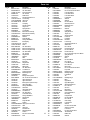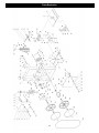
1
10” Woodworking Bandsaw
Owner’s Manual
Model: 10-300
Record the serial number and date of purchase
in your manual for future reference.
Serial number:
Date of purchase:
For more information:
www.rikontools.com or [email protected]
For Parts or Questions:
[email protected] or 877-884-5167
Part # 10-300M1
TABLE OF CONTENTS
Safety Instructions...............................................................................................................................................3-4
Carton Contents.....................................................................................................................................................5
Hardware Package Contents.................................................................................................................................5
Assembly.............................................................................................................................................................6
Installing the Table..........................................................................................................................................................6
Centering the Table..................................................................................................................................................6
Setting the Table Square with the Blade........................................................................................................................6
Mounting the Bandsaw....................................................................................................................................................7
Dust Collection...............................................................................................................................................................7
Installing/Changing the Blade...............................................................................................................................7-8
Tracking the Bandsaw Blade..........................................................................................................................................8
Adjusting the Blade Guides..............................................................................................................................................8
Setting the Cutting Height............................................................................................................................................8
Tilting the Bandsaw Table............................................................................................................................................8
Operation................................................................................................................................................................9
Maintenance............................................................................................................................................................9
Troubleshooting......................................................................................................................................................10
Electrical Schematic.............................................................................................................................................11
Electrical Requirements.........................................................................................................................12
Parts List..............................................................................................................................................................13
Parts Explosion....................................................................................................................................................14
Notes.....................................................................................................................................................................15
Warranty...............................................................................................................................................................16
SPECIFICATIONS
Throat width
Max. cutting depth
Blade length
Blade width
Table size
Table tilt
Blade speed
Motor
Amps
Volts
Net weight
9-5/8” (244 mm)
3-3/8” (86 mm)
67-1/2” (1714 mm)
1/8” – 1/2”(3-13 mm)
11-13/16” x 11-13/16”
Left-1o Right-45 o
2,780 ft/min
1/3 HP
4.5
110V
55 lbs
2
SAFETY INSTRUCTIONS
General Safety Warnings
KNOW YOUR POWER TOOL. Read the owner’s manual carefully. Learn the tool’s applications, work capabilities, and its
Always Ground All Tools.
If your tool is equipped with a three-pronged plug, you must plug it into a three-hole electric receptacle. If you
use an adapter to accommodate a two-pronged receptacle, you must attach the adapter plug to a known ground.
Never remove the third prong of the plug.
Always Avoid Dangerous Environments.
Never use power tools in damp or wet locations. Keep your work area well lighted and clear of clutter.
Always Remove the Adjusting Keys and Wrenches from Tools after Use.
Form the habit of checking to see that keys and adjusting wrenches are removed from the tool before turning it
on.
Always Keep Your Work Area Clean. Cluttered areas and benches invite accidents.
Always Keep Visitors Away from Running Machines.
All visitors should be kept a safe distance from the work area.
Always make the Workshop Childproof.
Childproof with padlocks, master switches, or by removing starter keys.
Never operate a tool while under the influence of drugs, medication, or alcohol.
Always Wear Proper Apparel.
Never wear loose clothing or jewelry that might get caught in moving parts. Rubber-soled footwear is
recommended for the best footing.
Always Use Safety Glasses and Wear Hearing Protection.
Also use a face or dust mask if the cutting operation is dusty.
3
Never Overreach.
Keep your proper footing and balance at all times.
Never Stand on Tools.
Serious injury could occur if the tool is tipped or if the cutting tool is accidentally contacted.
Always Disconnect Tools.
Disconnect tools before servicing and when changing accessories such as blades, bits, and cutters.
Always Avoid Accidental Staring.
Make sure switch is in “OFF” position before plugging in cord.
Never Leave Tools Running Unattended.
Always Check for Damaged Parts.
Before initial or continual use of the tool, a guard or other part that is damaged should be checked to assure that
it will operate properly and perform its intended function. Check for alignment of moving parts, binding of moving
parts, breakage of parts, mounting, and any other conditions that may affect its operation. A guard or other
damaged parts should immediately be properly repaired or replaced.
Special Safety Rules For Bandsaws
1. Always stop the Bandsaw before removing scrap pieces from table.
2. Always keep hands and fingers away from the blade.
3. Never attempt to saw stock that does not have a flat surface, unless a suitable support is used.
4. Always hold material firmly and feed it into the blade at a moderate speed.
5. Always turn off the machine if the material is to be backed out of an uncompleted cut.
6. Adjust the upper guide about 1/8” to 1/4” above the material being cut.
7. Check for proper blade size and type for thickness and type of material being cut.
8. Make sure that the blade tension and blade tracking are properly adjusted.
9. Make “relief” cuts before cutting long curves.
10. Release blade tension when the saw will not be used for a long period of time.
4
CARTON CONTENTS
CARTON CONTENTS
The model 10-300 10” Bandsaw is shipped complete in one
box.
Item
A
B
C
D
E
Unpacking and Checking Contents
a. Separate all parts from carton and check each item with
“Table of Carton Contents” to make sure all items are
accounted for, before discarding any packing material.
Description
Q’ty.
Main Machine..................................................................1
Table.......................................................................... .................1
Owner’s Manual.............................................................1
Upper Table Trunnion Assembly.....................................1
Bag of Loose Parts........................................................1
b. Remove the protective oil that is applied to the table. Use
any ordinary house hold type grease and spot remover.
c. Apply a coat of paste wax to the table to prevent rust.
Wipe all parts thoroughly with a clean dry cloth.
B
A
C
D
E
HARDWARE PACKAGE CONTENTS
Unpacking and Checking Contents
Separate all parts from loose bags and check each item with “Table of hardware package contents” to make sure all items
are accounted for, before discarding any packing material.
LIST OF LOOSE PARTS IN BAG
LIST OF LOOSE PARTS IN BAG
Item
Description
Item
Qty
Description
Qty
Blade Tension Knob............................................1
Hex. Bolt M6x12....................................................4
Miter Gauge...........................................................1
Lock Washer 6....................................................4
Hex. Socket Head Cap Screw M6x30...............1
M3 Hex “L” Wrench..............................................1
Washer 6...............................................................1
M5 Hex “L” Wrench..............................................1
Wing Nut M6..........................................................1
5
ASSEMBLY
Initial Assembly
The machine is supplied partly assembled. Prior to use, the
following items have to be installed: bandsaw table, star
knob (blade tensioning) and rip fence.
WARNING: To avoid injury, do not attempt to run or use
this machine until all parts are assembled and working
properly.
Installing the Table
a. Place table on to the upper table trunnion, taking care
when passing the saw blade through the slot in the table
(See Fig. 1). Mount the working table to the upper trunnion
with four hex bolts and four lock washers. (A--Fig. 2)
b. Use the hex socket screw, bushing, washer and wing nut
for correcting the working table flatness. (B--Fig. 2)
c. Place star knob on to tension rod (See Fig. 3).
Fig.1
Star Knob
Fig.2
Fig.3
Centering the Table
a. Loosen the four bolts mounting the table to the upper
trunnion. (A-Fig. 4)
b. Move table sideways as required, until saw blade runs
through the center of table insert.
A
c. If the adjustment of “b” is not enough to center the table,
loosen the bolts holding the lower table trunnion and move
the table sideways to place the table in the center. (B-Fig. 4)
B
Mounting Bolts
d. Re-tighten trunnion bolts, recheck blade position.
Fig.4
Setting the Table Square with the Saw Blade
Loosen the wing nut and place a suitably sized square
against the saw blade. If table requires adjustment, proceed
as follows:
Square
a. Using a 10mm wrench, release lock nut on the table stop.
b. Place wrench on bolt and adjust until table is set square
to blade.
Hex. bolt
c. Tighten M10 lock nut and recheck blade and table for
squareness.
d. Lock table into position and check that pointer reads zero
degrees on side of trunnion. Loosen then screw securing
pointer and reset if necessary to give zero degree reading
(See Fig. 5).
Hex. nut
Fig.5
6
Mounting the Bandsaw
For maximun stability during use, it is strongly
recommended that the bandsaw be mounted on a sturdy
bench or worktable. It should be bolted down utilizing the
1/4” holes in the bandsaw base plate. (See Fig. 6)
Dust Collection
The bandsaw has a 2-1/2” dust extraction port
(See Fig. 7) included.
It is recommended that when in use, the bandsaw is connected to a suitable dust collector.
Fig.6
Installing/Changing and Setting the Saw Blade
This bandsaw is factory-equipped with a general-purpose
wood cutting blade, the blade is set prior to delivery.
To change the blade, the following procedure must be
followed:
WARNING: To avoid injury from unexpected starting,
whenever changing blade or carrying out adjustments, switch
bandsaw off and remove power cord from the main outlet. To
avoid injury to hands when handling saw blade, wear gloves
whenever necessary.
Fig.7
a. Remove the leveling wing nut and screw from table.
b. Open top and bottom bandsaw wheel doors by releasing
the door locks.
c. Loosen the blade tension by turning the star knob on the
top of the upper wheel housing counter-clockwise (viewed
from above) (See Fig. 8).
d. Remove the saw blade by feeding it through the slot in the
table, upper blade guides and guard and the slot in the spine
of the bandsaw.
Fig.8
e. When fitting the new blade ensure the blade teeth are
pointing downwards and towards you at the position where
the blade passes through the table.
f. Re-tension the new blade and check the blade tracking by
turning the upper wheel by hand. The blade should run in the
center of the bandsaw wheel (See Fig. 9).
g. If required, adjust the tracking by using the tracking knob
and locking wing nut (See Fig. 10 page 8) to the rear of the
upper bandsaw wheel housing. When tracking is correct,
tighten the locking wing nut.
Fig.9
7
Installing/Changing and Setting the Saw Blade Cont.
h. Replace leveling wing nut and screw to table.
i. Close and lock both bandsaw wheel doors before reconnecting the power supply.
Wing Nut
Tracking Knob
Tracking the Bandsaw Blade
Set the tracking of the blade before setting the blade guides.
Once the blade is installed and tensioned, track the blade by
adjusting the tracking knob by hand (See Fig. 10). The blade
should run in the center of the bandsaw wheel as shown in
(See fig. 9). When the correct adjustment is achieved lock
the tracking knob with the wing nut. (See Fig. 10)
Fig.10
Adjusting the Blade Guides
The saw blade guides of this bandsaw ensure exact blade
position for clean cuts. When using narrow blades, ensure
that the upper and lower blade guides positively support the
blade from both sides and the rear (See Fig. 11).
Set the bearings of the upper and lower blade guides to
within approximately 1/64” of the blade. Adjust the rear upper
and lower thrust bearings to the back of the blade. Position
the thrust bearings so they do not spin while blade is
moving, only when pressure is applied to the blade during
cutting operation (See Fig. 12).
Fig.11
NOTE: Do not set bearings too close, as resulting friction
generates heat, which may have an adverse effect on the
bearings and the saw blade as well.
Setting the Cutting Height
a. The upper blade guide should always be set approximately 1/4” above the workpiece.
Fig.12
b. To adjust, loosen the wing nut at the side of the upper
wheel housing (See Fig. 13).
Wing Nut
c. Set the blade guide to the required height by raising or
lowering the blade guard by hand.
d. Tighten wing nut after proper height is set (See Fig. 13).
Fig.13
Tilting the Bandsaw Table
For bevel cuts, the bandsaw table tilts 0 through 45 degrees.
a. To tilt, loosen the wing nut on the table trunnion, set table
to the required angle and tighten the wing nut again.
(See Fig. 14)
b. It is recommended to verify the correct angle setting using
an angle guide, or by making trial cuts in scrap wood.
Adjust the pointer accordingly by using a phillips head
screwdriver.
Wing Nut
Fig.14
8
OPERATION
1. The blade cuts on a continuous down-stroke.
2. Check all the necessary settings and adjustments, and
ensure that all the recommended safety procedures are in
place.
3. Start the bandsaw by placing the switch towards the ‘on’
position.
4. Wait for the saw to come to full speed before starting to
cut. Never start the saw with the workpiece in contact with
the saw blade.
Fig.15
5. Slowly feed the workpiece towards the blade, putting only
light pressure on it.
6. With both hands, firmly hold the workpiece down on the
table, and feed it towards the blade slowly (See Fig. 15).
WARNING: To avoid injury when hands are unavoidably
near to the blade, they should be placed on either side of the
blade, not in line with it. Use a push stick whenever possible
when working in close proximity to the blade.
7. For best results the blade must be sharp.
8. Select the right blade for the job, depending on the
thickness of the wood to be cut. The thinner and harder the
wood, the finer the teeth of the blade. Use a fine tooth blade
for cutting sharp curves.
Fig.16
9. Use the fence provided to feed the workpiece along the
blade slowly and in a straight line.
10. The machine is especially suited for cutting curves, but
will also make straight cuts.
11. When cutting, follow the design marked out by pushing
and turning the workpiece evenly.
12. Do not attempt to turn the workpiece without pushing it,
as this may cause the workpiece to get stuck, or the blade
to bend.
13. Use the miter gauge for angle cutting (See Fig. 16).
9
MAINTENANCE
WARNING: To avoid injury due to unexpected starting,
before cleaning or carring out maintenance work, switch off
and disconnect the bandsaw from the power source.
Changing Drive Belt
1. Release saw blade tension by turning star knob on the top
of upper bandsaw cabinet counter-clockwise.
Never use water or other liquids to clean the bandsaw. Use a
dry brush.
2. Using a 6mm hexagonal wrench to release socket head
cap screw on motor mounting flange. (See Fig. 17)
Regular maintenance of the bandsaw will prevent unnecessary problems.
1. Keep the table clean to ensure accurate cutting.
Hex. socket head cap screw
2. Keep the outside of the machine clean to ensure accurate
operation of all moving parts and prevent excessive wear.
3. Keep the ventilation slots of the motor clean to prevent it
from overheating.
4. Keep the inside (near the saw blade, etc.) clean to prevent
accumulation of dust. Use dust collection if possible.
Fig.17
3. Using c-clip pliers (not provided) remove c-clip from center
of lower bandsaw wheel.
5. To prolong the life of the blade, when the bandsaw is not in
use for extended periods, release the blade tension. Before
reusing the bandsaw ensure that the blade is re-tensioned
and tracking is checked.
4. Carefully slide bandsaw wheel forward and at the same
time release saw blade from wheel.(See Fig. 18)
Fig.18
5. Remove old drive belt and fit new belt. Make sure ribs in
drive belt are seated correctly before reassembly and
tensioning belt.
6. Follow procedure for Changing and Setting Blade /
Tracking the Bandsaw Blade Guide, before restoring power
to the saw and setting up for use.
10
TROUBLE SHOOTING
Problem
Diagnosis
Remedy
The machine does not work when
switched on.
1. No power supply.
2. Defective switch.
1. Check the cable for breakage.
2. Check the fuse or breaker.
3. Contact you local dealer for repair
parts.
The blade does not move with the motor
running.
1. The blade tension knob has not been
tightened.
2. The blade has come off one of the
wheels.
3. The saw blade has broken.
4. The drive belt has snapped.
1. Switch off the motor, tighten the blade
tension knob.
2. Open the hinged door and check.
1. Fence for cutting not used.
2. Feed rate too fast.
1. Use a fence.
2. Put light pressure on the workpiece.
Make sure the blade does not bend.
3. Try a new blade.
4. Adjust the blade guides(see assembly)
The blade does not cut in a straigt line.
3. The blade teeth are dull or damaged.
4. Blade guides not suitably adjusted.
The blade does not cut, or cuts very
slowly.
1. The teeth are dull, caused by cutting
hard material or long use.
2. The blade was fitted the wrong way on
the bandsaw.
3. Replace the blade.
4. Replace the belt.
1. Replace the blade, use a 6 T.P.I. blade
for wood and soft material. Use a 14 T.P.I.
blade for harder materials. A 14 T.P.I.
blade always cuts slower due to the finer
teeth and the slower cutting performance.
2. Install the blade correctly.
Sawdust builds up inside the machine.
Excessive dust build-up on the
machine interior components.
Clean the machine regularly. Attach to a
suitable dust collection system.
Sawdust inside the motor housing.
Excessive dust build-up on the
machine exterior components.
Clean the ventilating slots of the motor
with a vacuum cleaner. From time to time
remove the sawdust to prevent it from
being drawn into the housing.
The machine does not cut at 45 or 90
degrees.
1. The table is not at right angles to the
blade.
2. The blade is dull or too much pressure
was put on the workpiece.
1. Adjust the table.
1. The wheels are not in alignment or
defective bearing.
2. The wheel alignment knob hasn’t been
properly adjusted.
3. Inferior blade.
1. Contact you local dealer for repair
parts.
2. Adjust the knob (See instructions).
The blade can not be properly positioned
on the bandsaw wheel.
ELECTRICAL SCHEMATIC
WARNING:
This machine must be grounded.
To avoid electrocution or fire, any repairs to electrical system
should be done only by a qualified electrician, using
genuine replacement parts.
11
2. Replace the blade or put less pressure
on the workpiece.
3. Replace the blade.
Eletrical Requirements
In the event of a malfunction or breakdown, grounding provides a path of least resistance for electric
current to reduce the risk of electric shock. This tool is equipped with an electric cord having an
equipment-grounding conductor and a grounding plug. The plug must be plugged into a matching outlet
that is properly installed and grounded in accordance with all local codes and ordinances.
Do not modify the plug provided. If it will not fit the outlet, have the proper outlet installed by a qualified
electrician.
Improper connection of the equipment-grounding conductor can result in a risk of electric shock. The
conductor, with insulation having an outer surface that is green with or without yellow stripes, is the
equipment-grounding conductor. If repair or replacement of the electric cord or plug is necessary, do not
connect the equipment-grounding conductor to a live terminal.
Check with a qualified electrician or service personnel if the grounding instructions are not completely
understood, or if in doubt as to whether the tool is properly grounded.
Use only three wire extension cords that have three-prong grounding plugs and three-pole receptacles
that accept the tool’s plug.*
Repair or replace a damaged or worn cord immediately.
This tool is intended for use on a circuit that has an outlet that looks the one illustrated in Figure A below.
The tool has a grounding plug that looks like the grounding plug as illustrated in Figure A below. A
temporary adapter, which locks like the adapter as illustrated in Figure B below, may be used to connect
this plug to a two-pole receptacle, as shown in Figure B if a properly grounded outlet is not available.**
The temporary adapter should only be used until a properly grounded outlet can be installed by a
qualified electrician. The green colored rigid ear or tab, extending from the adapter, must be connected
to a permanent ground such as a properly grounded outlet box.
* Canadian electrical codes require extension cords to be certified SJT type or better.
** Use of an adapter in Canada is not acceptable.
12
Parts List
Key No.
1
2
3
4
5
6
7
8
9
10
11
12
13
14
15
16
17
18
19
20
21
22
23
24
25
26
27
28
29
30
31
32
33
34
35
36
37
38
39
40
41
42
43
44
45
46
47
48
49
50
51
52
53
54
55
56
57
58
59
60
61
62
63
64
64
66
Part#
JL20061101-081S
1-M6X40GB5781Z
1-JL20061102-081S
1-M6GB6172Z
1-JL20010010D
1-JL20010014
1-JL20010011A001S
1-JL22012000B049W
1-RVT4X8GB12618A
1-JL22010008
1-JL20010012
1-JL20010009
1-WSH6GB93Z
1-M6GB889ZF
1-JL22024001-001S
1-JL22024002-001S
1-JL22021003
1-WSH8GB97D1Z
1-M6GB6177Z
1-M8X50GB14Z
1-JL20010001
1-JL22010001A-001S
1-JL22011000-050W
1-M6X12GB5781B
1-JL20061101-001S
1-JL20061102-081S
1-M6X60GB5781Z
1-M6GB6172Z
1-JL22020002-001S
1-WSH6GB96Z
1-JL22041009
1-M8X20GB14Z
1-JL20041004
1-JL20010016-001S
1-JL22041001E
1-JL20010005A
1-M6X12GB5781B
1-WSH6GB862D2Z
1-JL22042005
1-BRG80026GB278
1-WSH6GB97D1Z
1-JL22042004
1-M6X10GB80B
1-JL22041003
1-JL22042002
1-JL22042003
1-JL22042001
1-M6X30GB14Z
1-JL22030002-001S
1-JL22032001
1-WSH6GB862D2Z
1-M6X12GB5781Z
1-JL22030001
1-M6X16GB14Z
1-JL22020002-001S
1-WSH6GB96Z
1-M6GB6177Z
1-1506003
1-ST3D5X9D5GB845Z
1-JL22031001-001G
1-JL22031002-001S
1-JL60040002
1-JL60040001-001S
1-JL60040004
1-M5X6GB818B
1-JL60040003-001S
Description
Knurled Knob Cap
Hex. Bolt M6x45
Knurled Knob Body
Hex. Nut M6
Slotted Insert
Special Spring Washer 10
Lock Housing
Upper Door
Rivet 4x8
Leaf Spring
Special Nut M22
Tongue Lock
Spring Washer 6
Lock Nut M6
Blade Tension Knob Cap
Blade Tension Knob Body
Blade Tensioner
Washer 8
Flange Nut M6
Carriage Bolt M8x50
Bushing Ring
Top Plug
Frame
Hex. Bolt M6x12
Blade Tracking Knob Cap
Blade Tracking Knob Body
Hex. Bolt M6x60
Hex. Nut M6
Wing Nut M6
Washer 6
Slider
Carriage Bolt M8x20
Bolt Guide
Wing Nut M8
Blade Guide
Sliding guide
Hex. Bolt M6x12
Lock Washer 6
Guide Adjust Screw
Ball Bearing 6mm
Washer 6
Bearing Mount Cylinder
Hex. Socket Set Screw M6x10
Upper Guide Mount
Upper Guide Shaft
Bearing Mount Cylinder w/Cap
Upper Guide Body
Carriage Bolt M6x30
Glide Piece
Upper Table Trunion
Lock Washer 6
Hex. Bolt M6x12
Lower Table Trunion
Carriage Bolt M6x16
Wing Nut M6
Washer 6
Flange Nut M6
Indicator
Tapping Screw ST3.5x9.5
Table
Table Insert
Aluminium Bar
Miter Gauge Base
Indicator
Pan Head Screw M5x6
Knob
Key No.
67
68
69
70
71
72
73
74
75
76
77
78
79
80
81
82
83
84
85
86
87
88
89
90
91
92
93
94
95
96
97
98
99
100
101
102
103
104
105
106
107
108
109
110
111
112
113
114
115
116
117
118
119
120
121
122
123
124
125
126
127
128
129
130
13 131
132
Part#
1-JL22042004
1-M6X10GB80B
1-JL22043001
1-JL22043002
1-JL22043003
1-M6GB889Z
1-WSH6GB97D1Z
1-WSH6GB96Z
1-M6X20GB5783Z
1-JL22042005
1-BRG80026GB278
1-JL22040004
1-WSH6GB97D1Z
1-M6GB889ZF
1-WSH6GB93Z
1-JL20010009
1-JL20010012
1-JL22013000-049W
1-JL22010008
1-RVT4X8GB12618A
1-JL20010011-001S
1-JL20010014
1-JL20010010D
1-M6GB6172Z
1-JL20061102-081S
1-M6X40GB5781Z
1-JL20061101-081S
1-M8X30GB70B
1-WSH8GB93Z
1-WSH8GB97D1Z
1-G7412634A
1-M6X20GB5783Z
1-M6GB6170Z
1-JL22020004
1-M14GB6171Z
1-JL22071001
1-M6X10GB80B
1-JL22020003
1-BRG80101GB278
1-CLP28GB893D1B
1-JL22023001
1-JL22022002
1-CLP12GB894D1B
1-JL22020001
1-JL22022001
1-JL22021006
1-JL23021001-050W
1-M14GB6171Z
1-JL22021004
1-JL22021002
1-JL22021001-050W
1-M8X70GB14Z
1-JL20010004
1-M8GB6177Z
1-M6X35GB12Z
1-M6GB6170Z
2-U23182300-472
1-WSH4GB862D2Z
1-WSH4GB97D1Z
1-M4X8GB818Z
1-JL20070002
1-J-9301B
1-M4X10GB823Z
1-JL22021100-050W
1-JL20072003
1-WSH8GB96Z
Description
Bearing Mount Cylinder
Hex. Socket Set Screw M6x10
Lower Guide Body
Lower Guide Shaft
Lower Guide Mount
Lock Nut M6
Washer 6
Washer 6
Hex. Bolt M6x20
Guide Adjust Screw
Ball Bearing 6mm
Guide Key
Washer 6
Lock Nut M6
Spring Washer 6
Tongue Lock
Special Nut M22
Lower Door
Leaf Spring
Rivet 4X8
Lock Housing
Special Spring Washer 10
Slotted Insert
Hex. Nut M6
Knurled Knob Body
Hex. Bolt M6x40
Knurled Knob Cap
Hex. Socket Head Cap Screw M8x30
Spring Washer 8
Washer 8
Motor
Hex. Bolt M6x20
Hex. Nut M6
Lower Bearing Bolt
Hex. Nut M14
Motor Pulley
Hex. Socket Set Screw M6x10
Poly-V-Belt
Ball Bearing 12mm
Retaining Ring 28
Lower Wheel
Tire
Retaining Ring 12
Blade
Upper Wheel
Upper Bearing Bolt
Wheel Carrier Bracket
Hex. Nut M14
Star Lock
Mount Shaft
Blade Tensioner
Carriage Bolt M8x70
Brush Strip
Flange Nut M8
Hex. Bolt M6x35
Hex. Nut M6
Cable w/Plug
Lock Washer 4
Washer 4
Pan Head Screw M4x8
Switch Cover Plate
Lock Switch
Pan Head Screw M4x10
Tension Bracket
Rubber Tube
Washer 8
Parts Explosion
14
Notes
15
Warranty
2-Year Limited Warranty
RIKON Power Tools/Richen Enterprise, Inc. (“Seller”) warrants to only the original retail consumer/
purchaser of our products that each product be free from defects in materials and workmanship for a
period of two (2) years from the date the product was purchased at retail. This warranty may not be
transferred.
This warranty does not apply to defects due directly or indirectly to misuse, abuse, negligence, accidents,
repairs, alterations, lack of maintenance or normal wear and tear. Under no circumstances will Seller be
liable for incidental or consequential damages resulting from defective products. All other warranties,
expressed or implied, whether of merchantability, fitness for purpose, or otherwise are expressly
disclaimed by Seller. This warranty does not cover products used for commercial, industrial or
educational purposes.
This limited warranty does not apply to accessory items such as blades, drill bits, sanding discs or belts
and other related items.
Seller shall in no event be liable for death, injuries to persons or property, or for incidental, contingent,
special, or consequential damages arising from the use of our products.
To take advantage of this warranty proof of purchase documentation, which includes date of purchase
and an explanation of the complaint, must be provided.
The Seller reserves the right to effect at any time, without prior notice, those alterations to parts, fittings,
and accessory equipment which they may deem necessary for any reason whatsoever.
To take advantage of this warranty, please fill out the enclosed warranty card and send it to:
RIKON Warranty
400 West Cummings Park
Suite 1000
Woburn, MA 01801
The card must be entirely completed in order for it to be valid. If you have any questions please
contact us at 877-884-5167 or [email protected].
16
For more information:
400 West Cummings Park, Suite 1000
Woburn, MA 01801
877-884-5167/781-933-8400
[email protected]
www.rikontools.com
Copyright Richen Enterprise, Inc. 2005
Printed in China 11/05