1
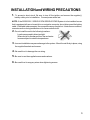
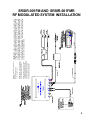
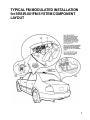
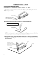
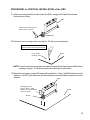
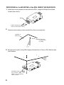
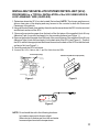
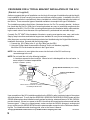
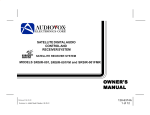
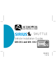
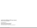
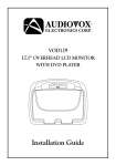
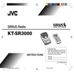
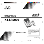
SATELLITE DIGITAL AUDIO
RECEIVER SYSTEM MODELS SRSIR-001,
SRSIR-001FM and MODEL SRSIR-001FMR
®
INSTALLATION MANUAL
For Customer Service
Visit Our Website At
WWW.audiovox.com
Product Information, Photos,
FAQ’s Owner’s Manuals
INTRODUCTION
The Audiovox Electronics SIRIUS® Satellite Digital Audio Control And Receiver System
(Model SRSIR-001 and SRSIR-001FM) was developed to allow the user to listen to a huge
selection of programming supplied by a subscription to SIRIUS® Radio. (SIRIUS® compatible antenna required).
The Audiovox Electronics SIRIUS® Satellite Digital Audio Control And Receiver System is
easily installed using the installation instructions herein, and is designed to work with the
user’s existing car stereo system through an unused FM frequency or the auxiliary audio
inputs. The programming and use of this system is described in detail in the supplied Owner’s
Manual.
The Audiovox Electronics SIRIUS® Satellite Digital Audio Control and Receiver System comes
with a satellite RADIO RECEIVER UNIT (RRU), a SATELLITE SYSTEM CONTROL UNIT
(SCU) allows the user to select an exact SIRIUS® Radio channel on the easy to read display.
The controller is compact, pleasantly designed and can be mounted in the cab of the vehicle
in numerous ways. This Installation Guide depicts typical installation scenarios.
It is important that the installer reads and understands all of the installation procedures for
each of the components to be installed, either supplied with the Audiovox Electronics SIRIUS
Satellite Digital Audio Control and Receiver System (Model SRSIR-001 / SRSIR-001FM/
SRSIR-001FMR) or equipment that is to be installed in conjunction with the system such as
the SIRIUS® Antenna.
The Audiovox Electronics SIRIUS® Satellite Digital Audio Control and Receiver System (Model
SRSIR-001/ SRSIR-001FM) comes with a 36 month limited warranty (see the back cover of
the owner’s manual for details)
TRADEMARKS
SIRIUS® is a registered trademark of Sirius Satellite Radio Inc. All rights reserved.
www.siriusradio.com
PRO.Fit® and VSM® are registered trademarks of Pro.Fit International. All rights reserved.
www.pro-fit-intl.com
Other product names mentioned in this manual may be trademarks or registered trademarks of their respective companies and are hereby acknowledged.
2
INSTALLATION and WIRING PRECAUTIONS
1.
To prevent a short-circuit, Be sure to turn off the ignition and remove the negative(-)
battery cable, prior to installation. Connect power wires last.
NOTE: If the SRSIR-001 / SRSIR-001FM/ SRSIR-001FMR System is to be installed in a car
that is equipped with an on-board drive or navigation computer, do not disconnect the battery
cable. If the cable is disconnected, the computer memory may be lost. Under these conditions,
use extra caution during installation not to cause a short circuit.
2. Do not install the unit in the following locations:
Locations exposed to direct sunlight.
Where hot air is discharged from the car heater.
In areas subject to extreme temperatures.
3. Incorrect installation may cause damage to the system. Mount the unit firmly in place, using
the supplied brackets and screws.
4. Be careful not to damage the car wiring.
5. Be sure to use the supplied screws and washers.
6. Be careful not to snag any wires when tightening screws.
3
PACKING LIST
SRSIR-001 / SRSIR-001FM / SRSIR-001FMR
(NOTE: Components are not drawn to scale.)
MAIN SYSTEM COMPONENTS
RADIO RECEIVER UNIT
(RRU) SRSIR-001FM AND
SRSIR-001FMR
RADIO RECEIVER
UNIT (RRU) SRSIR-001
P/N 144D2346
SATELLITE SYSTEM
CONTROL UNIT (SCU)
P/N 144D2345
P/N 144D2347
AUDIO OX
TER.
SAT.
AUDIO OX
-or-
L
TO SCU
2
3
4
5
6
7
8
9
0
AUDIO OX
AUDIO OUT
R
1
TER.
POWER
SAT.
AUDIO OUT
R
L
FM
OUT
TO SCU
POWER
1 pc.
1 pc.
SFT
1 pc.
INSTALLATION PARTS
RCA to RCA Cable
P/N 112C3157 (6 Meter)
(w/ (2)Fuse,AGC Style 250 V-2Amp)
P/N 112B3114 (6 Meter)
Used to connect the RRU to
an external audio device.
P/N 112C3158 (6 Meter)
To connect the RRU to the SCU
1 pc.
1 pc.
1 pc.
RRU - HARDWARE KIT - P/N 1501418
SCU - HARDWARE KIT- P/N 1501442 FM SWITCHING
Phillips Round Head
Screw (4mm x 8mm)
Phillips Pan Head
Screw (5mm x 15mm)
Phillips Round Head
Screw (4mm x 8mm)
4 pcs
4 pc.
4 pcs
Split Lock Washer,M4
Flat Washer,M4
External Tooth
Lock Washer
4 pcs
4 pc.
4 pcs
RRU Mounting
Bracket
P/N 108B3621
SUPPLIED ACCESSORIES
Quick Reference
Card
Owner's Manual
P/N 1286374
P/N 1286376
2 pc.
1 pc.
4
Din Cable, 6 - pin
Power Wire Harness
1 pc.
Hook & Loop
Adhesive Tape
BOX ASSY
P/N 112C3159 (6 Meter)
(SRSIR-001FM only)
1 cut set.
1 pc.
OPTIONAL ACCESSORIES
Satellite Radio Wireless Remote
Control Model
#SAT-RC
TER.
SAT.
R
L
AUDIO OUT
FM
OUT
TO SCU
AUDIO OX
POWER
NOTE: “C” Before routing the Din Cable to
connect the SCU to the RRU, observe the
gender (Male / Female connector) of the cable
to avoid any unnecessary re-work. The Female
connector is matched to the SCU and the
Male connector is matched to the RRU.
NOTE: “B” RCA to RCA Cable (supplied
with system) used to connect the RRU Audio
Ouput to the Radio Reciever Audio Input.
NOTE: “A” To Satellite Radio Antenna (Sold
separately)
*White =Terrestrial connection
*Yellow = Satellite connection
AUDIO OX
8
4
SFT
0
2
5
1
7
9
6
3
IMPORTANT - Some vehicles use a special dual antenna “Diversity" system.
If the vehicle into which this system is being installed has this type of antenna
system, the antenna cable will not fit the socket on the FM modulator. Use
of the SRSIR-001FM system with “Diversity" systems is not recommended.
You may also find some cars have an antenna plug that is too small to mate
with the socket on the FM modulator. If this is the case, call Audiovox’s TollFree Assistance for a special adaptor. This adaptor can also be purchased
at most car stereo installation centers.
SRSIR-001FM AND SRSIR-001FMR
RF MODULATED SYSTEM INSTALLATION
5
6
TER.
SAT.
R
L
AUDIO OUT
TO SCU
AUDIO OX
POWER
AUDIO OX
5
8
4
7
SFT
0
2
1
9
6
3
TYPICAL FM MODULATED INSTALLATION
for SRSIR-001FM SYSTEM COMPONENT
LAYOUT
7
SYSTEM INSTALLATION
RADIO RECEIVER UNIT (RRU)
PROCEDURE for HORIZONTAL INSTALLATION of the RRU
1. Attach the mounting brackets to each side of the RRU, using the 4 Phillips Round Head
Screws (4mm x 8mm).
Bracket
Phillips Head Screws (4mm x
8mm) used in 4 places
2. Determine the mounting location and drill 4x 1/8” (4mm) mounting holes.
WARNING
Never mount the unit near the fuel tank.
4x 1/8” (4mm)
mounting holes
Carpet
NOTE:If mounting surface is carpeted, use caution when drilling holes to prevent drill bit from
catching on carpet. Cut holes in carpet before drilling into subsurface.
3. Mount the unit in place, using 4 Self-tapping Screws (5mm x 15mm), w/Flat Washers and
Lock Washers. Use RTV (silicone sealer) on screw threads or around the holes to prevent
moisture intrusion.
RRU
Self-tapping Screw
(5mm x 15mm), w/Flat
Washers and Lockwashers
used in 4 places
Bracket
8
Carpet
PROCEDURE for VERTICAL INSTALLATION of the RRU
1. Attach a mounting bracket to each side of the RRU, using the 4 Phillips Round Head
Screws (4mm x 8mm).
RRU
Phillips Head Screws (4mm x
8mm) used in 4 places
Bracket
2. Determine the mounting location and drill 4 x 1/8” (4mm) mounting holes.
WARNING
Never mount the unit near the fuel tank.
4x 1/8” (4mm)
mounting holes
Carpet
NOTE: If mounting surface is carpeted, use caution when drilling holes to prevent drill bit from
catching on carpet. Cut holes in carpet before drilling into subsurface.
3. Mount the unit in place, using 4 Self-tapping Screws (5mm x 15mm), w/Flat Washers and Lock
Washers. Use RTV (silicone sealer) on screw threads or around the holes to prevent moisture
intrusion.
RRU
Self-tapping Screw
(5mm x 15mm), w/Flat
Washers and Lockwashers
used in 4 places
Carpet
Bracket
9
PROCEDURE for the MOUNTING of the RRU UNDER THE REAR DECK
1. Attach the mounting brackets to each side of the RRU, using the 4 Phillips Round Head
Screws (4mm x 8mm).
Bracket
Phillips Head Screws
used in 4 places (4mm x 8mm)
2.
Determine the mounting location and drill four 4mm mounting holes.
Underside of
Rear Deck
4x 1/8” (4mm)
mounting holes
(4 places)
3. Mount the unit in place, using 4 Self-tapping Screws (5mm x 15mm), w/Flat Washers and
Lock Washers.
Rear
Deck
Self-tapping Screw
(5mm x 15mm), w/Flat
Washers and Lockwashers
used in 4 places
10
INSTALLING THE SATELLITE SYSTEM CONTROL UNIT (SCU)
PROCEDURE for a TYPICAL INSTALLATION of the SCU USING HOOK &
LOOP ADHESIVE TAPE (SUPPLIED)
1. Determine where the SCU is to be located (flat surface) NOTE: The chosen position must
allow a clear view of the display and easy access to the controls for both the Driver and
Passenger of the vehicle.
2. Using an Alcohol Swab, clean and dry the entire surface area where the SCU is to be mounted
and the back surface of the SCU.
3. Remove the protective paper from the back of the first piece of the supplied Hook & Loop
Adhesive Tape (Loop side) and apply it to the mounting surface (see Figure 1.)
4. Remove the protective paper from the back of the second piece of the supplied Hook & Loop
Adhesive Tape (Hook side) and apply it to the back side of the SCU (see Figure 2.). Position
the SCU cable in the appropriate directional channel on the back of the SCU so that the back
surface is flat (see Figure 3.).
5. Carefully press the SCU into place.
6. Connect the SCU Cable to the 6 - pin Din Cable from the RRU
Velcro Tape (Loop)
Hook & Loop Adhesive Tape (Hook)
Figure 2.
Figure 1.
Figure 3.
NOTE: Do not install the unit in the following locations:
In Locations exposed to direct sunlight.
Where hot air is discharged from the car heater.
In areas subject to extreme temperatures.
11
PROCEDURE FOR A TYPICAL BRACKET INSTALLATION OF THE SCU
(Bracket not supplied)
Audiovox suggests this type of installation over the Hook & Loop type of installation though the Hook &
Loop installation (if done correctly) is a secure and sufficient mounting option. Installation of the SCU
using a bracket results in a professional, factory-installed look, without visibly damaging the interior of
the vehicle. There are several types of brackets available to accomplish this type of installation.
The installation procedure that follows, illustrates the use of a Pro.Fit® mounting bracket. Audiovox
has found that the Pro.Fit® VSM® line of mounting brackets are easy to install and compliments the
installation of the SCU. Pro.Fit® VSM® mounting bracket reduce the installation liability while maintaining the resale value of a car because of the professional fit, professional look and safe design.
Currently Pro.Fit® VSM® offers hundreds of brackets, covering most popular cars, vans, and trucks.
Step-by-step instructions and technical support are available for every mount and application.
After the proper mounting bracket has been selected and installed using the Original Manufacturers
installation instructions, proceed with the following steps:
1. Connect the SCU Cable to the 6 - pin Din Cable from the RRU
2. Using the Phillips Head Screws and the External Tooth Lock Washers (supplied),
Mount the SCU to the bracket as shown in the Figure below.
NOTE: Use caution not to over tighten the screws into the back of the SCU as this may
cause damage to the unit.
NOTE: Do not install the unit in the following locations:
In Locations exposed to direct sunlight. Where hot air is discharged from the car heater. In
areas subject to extreme temperatures.
(Example installation position)
1
4
7
2
3
5
6
8
9
Phillips Round Head Screw (4mm x 8mm)
0
AUDIO OX
SFT
External Tooth Washer
(4mm int.)
Bracket
SCU
(Not Supplied)
Bracket Shown is a PRO.FIT for ordering information
visit www.pro-fit-intl.com
Upon completion of the SCU installation and before the SIRIUS® radio is activated a test of the system
should be performed. To verify that the SRSIR-001/ SRSIR-001FM/ SRSIR-001FMR System and the
SIRIUS® Antenna have been installed correctly and are functioning, select and listen to CH 184. (SIRIUS®
preview channel). If there is no power to the SCU check that all connections have been made and that
fuses are good. If there is no signal present, make sure that the SIRIUS® Antenna is unobstructed
(move vehicle) and for SRSIR-001FM check the antenna cable connection to the FM Antenna Switching Box For a detailed trouble-shooting guide, refer to the Owner’s Manual.
© Copyright 2002 Audiovox Electronics Corp. 150 Marcus Blvd. Hauppauge, NY 11788
12
128-6375A