1
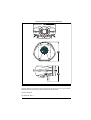
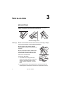
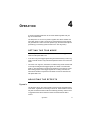
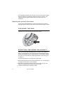
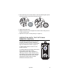
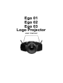
Ego 01
Ego 02
Ego 03
Logo Projector
user manual
Measurements are expressed in millimeters.
324
305
150
248
© 2002-2004 Martin Professional A/S, Denmark.
All rights reserved. No part of this manual may be reproduced, in any form or by any means,
without permission in writing from Martin Professional A/S, Denmark.
Printed in Denmark.
P/N 35000109, Rev. H
CONTENTS
Introduction . . . . . . . . . . . . . . . . . . . . . . . . . . . . . . . . . . . . . . . .4
Ego 01 / Logo Projector . . . . . . . . . . . . . . . . . . . . . . . . . . . . . . . . . . . . . . . . .
Ego 02 . . . . . . . . . . . . . . . . . . . . . . . . . . . . . . . . . . . . . . . . . . . . . . . . . . . . . . .
Ego 03 . . . . . . . . . . . . . . . . . . . . . . . . . . . . . . . . . . . . . . . . . . . . . . . . . . . . . . .
Safety information . . . . . . . . . . . . . . . . . . . . . . . . . . . . . . . . . . . . . . . . . . . . . .
Unpacking . . . . . . . . . . . . . . . . . . . . . . . . . . . . . . . . . . . . . . . . . . . . . . . . . . . .
4
4
5
5
6
AC power . . . . . . . . . . . . . . . . . . . . . . . . . . . . . . . . . . . . . . . . . .7
Installing a plug on the mains lead . . . . . . . . . . . . . . . . . . . . . . . . . . . . . . . . . 7
Installation . . . . . . . . . . . . . . . . . . . . . . . . . . . . . . . . . . . . . . . . .8
Mounting . . . . . . . . . . . . . . . . . . . . . . . . . . . . . . . . . . . . . . . . . . . . . . . . . . . . . 8
Linking multiple Egos for simultaneous control . . . . . . . . . . . . . . . . . . . . . . . 10
Operation . . . . . . . . . . . . . . . . . . . . . . . . . . . . . . . . . . . . . . . . .11
Setting the trig mode . . . . . . . . . . . . . . . . . . . . . . . . . . . . . . . . . . . . . . . . . . .
Adjusting the effects . . . . . . . . . . . . . . . . . . . . . . . . . . . . . . . . . . . . . . . . . . .
Focusing the Ego . . . . . . . . . . . . . . . . . . . . . . . . . . . . . . . . . . . . . . . . . . . . .
Selecting the gobo on an Ego 2 . . . . . . . . . . . . . . . . . . . . . . . . . . . . . . . . . .
Operation with the optional remote control . . . . . . . . . . . . . . . . . . . . . . . . . .
11
11
12
12
13
Basic service . . . . . . . . . . . . . . . . . . . . . . . . . . . . . . . . . . . . . .14
Cleaning . . . . . . . . . . . . . . . . . . . . . . . . . . . . . . . . . . . . . . . . . . . . . . . . . . . .
Lamp maintenance . . . . . . . . . . . . . . . . . . . . . . . . . . . . . . . . . . . . . . . . . . . .
Fuses . . . . . . . . . . . . . . . . . . . . . . . . . . . . . . . . . . . . . . . . . . . . . . . . . . . . . .
Gobo replacement or removal (Ego 2) . . . . . . . . . . . . . . . . . . . . . . . . . . . . .
Firmware updates . . . . . . . . . . . . . . . . . . . . . . . . . . . . . . . . . . . . . . . . . . . . .
14
15
16
17
17
Troubleshooting . . . . . . . . . . . . . . . . . . . . . . . . . . . . . . . . . . .18
Specifications . . . . . . . . . . . . . . . . . . . . . . . . . . . . . . . . . . . . .19
3
1
INTRODUCTION
Thank you for selecting a Martin Ego. The Ego series features 250 watt
flower effects with sharp projection quality optics in a moulded compositeplastic casing. They incorporate a 250-watt halogen lamp and a precise
focus adjustment that produces crisp projections.
Variable behavior tuning, by adjusting the dynamic, allows you to modify
the aggressiveness of the effect in relationship to the music - relaxed,
intermediate or quick. The Ego operates in either automatic or musicactivated trigger mode.
A convenient handle and lens protection ring make for easy transport and
handling. A remote control is also available that enables the simultaneous
control of multiple Ego fixtures.
EGO 01 / LOGO PROJECTOR
The Ego 01 provides a flower effect with a range of gobos and colors on a
single effect wheel. In addition to variable behavior tuning, effect wheel
and mirror dish rotation speeds are controllable.
The Logo Projector is the same as the Ego 01, but it is primarily used to
project images around a specific theme.
EGO 02
The Ego 02 features an overlapping color wheel system offering more
than 200 color combinations and a manually selectable image effect
(etched gobo or textured glass gobo pattern). An interchangeable gobo
slot is available so that you can incorporate your own custom patterns or
accessories. In addition to variable behavior tuning, the rotation speeds of
the color wheels and mirror dish are also controllable.
4
Ego user manual
EGO 03
The Ego 03 is a kaleidoscopic effect with a range of gobo and color
combinations on a single effect wheel that are projected onto a series of
mirrored tunnels. In addition to variable behavior tuning, effect wheel and
mirrored-tunnel rotation speeds are controllable.
SAFETY INFORMATION
Warning!
This product is not for household use. It presents risks of
lethal or severe injury due to fire and heat, electric shock, and
falls.
Read this manual before powering or installing the fixture, follow the
safety precautions listed below and observe all warnings in this manual
and printed on the fixture. If you have questions about how to operate the
fixture safely, please contact a Martin distributor for assistance. Refer any
service operation not described in this manual to a qualified technician.
Do not modify the fixture or install other than genuine Martin accessories
and upgrade kits.
Avoi di ng electric shocks
• Disconnect the fixture from AC power before removing or installing the
lamp, fuses, or any part, and when not in use.
• Always ground (earth) the fixture electrically.
• Use only a source of AC power that complies with local building and
electrical codes and has both overload and ground-fault protection.
• Do not expose the fixture to rain or moisture.
• Refer all service to a qualified technician.
• Never operate the fixture with missing or damaged lenses and/or covers.
Protecting yourself and others from burns an d fire
• Never attempt to bypass the thermostatic switch or fuses. Always replace
defective fuses with ones of the specified type and rating.
• Ensure that the air flow through fans and vents is free and unobstructed.
• Keep all combustible materials (for example fabric, wood, paper) at least
0.1 meters (4 inches) away from the fixture. Keep flammable materials
well away from the fixture.
• Do not illuminate surfaces within 0.3 meters (12 inches) of the fixture.
Introduction
5
• Provide a minimum clearance of 0.1 meters (4 inches) around fans and air
vents.
• Replace the lamp if it becomes defective or worn out, or before usage
exceeds the maximum service life. When replacing the lamp, allow the
fixture to cool for at least 5 minutes before opening the fixture or removing
the lamp. It can take up to 15 minutes for the fixture to cool completely.
• Never place filters or other materials over the lens or mirror drum.
• The exterior of the fixture can become hot. Allow the fixture to cool for at
least 5 minutes before handling.
• Do not operate the fixture if the ambient temperature (Ta) exceeds 40° C
(104° F).
• Do not stare directly into the light.
• Never operate the fixture without all lenses and covers installed: an
unshielded lamp emits dangerous UV radiation that can cause burns and
eye damage.
Preventing injuri es due to fall s
• When suspending the fixture above ground level, verify that the structure
can hold at least 10 times the weight of all installed devices.
• Verify that all external covers and rigging hardware are securely fastened
and use an approved means of secondary attachment such as a safety
cable.
• Block access below the work area whenever installing or removing the
fixture.
UNPACKING
The packing material is carefully designed to protect the fixture during
shipment - always use it to transport the fixture.
The Ego comes with the following:
• 3-meter, 3-wire IEC power cable
• User manual
6
Ego user manual
2
AC POWER
The Ego has an auto-ranging power supply that can operate in the
following voltage ranges at 50-60 Hz:
• 90-130 volts
• 200-250 volts
INSTALLING A PLUG ON THE MAINS
LEAD
The fixture’s mains lead may require a grounding-type cord cap that fits
your power distribution cable or outlet. Consult a qualified electrician if
you have any doubts about proper installation.
Warning!
For protection from dangerous electric shock, the fixture must
be grounded (earthed). The AC mains supply shall have
overload and ground-fault protection.
Important! Verify that the feed cables are undamaged and rated for the
current requirements of all connected devices before use.
Following the cord cap manufacturer’s instructions, connect the yellow
and green wire to ground (earth), the brown wire to live, and the blue wire
to neutral. The table below shows some pin identification schemes.
Wire
Pin
Marking
Screw color
brown
live
“L”
yellow or brass
blue
neutral
“N”
silver
yellow/green
ground
AC power
green
7
3
INSTALLATION
MOUNTING
Ego fixtures can be flown using a clamp (available from your Martin
dealer), or fastened to a horizontal or vertical surface.
Surface mounting options
Warning!
Block access below the work area before proceeding. Always
use a secure means of secondary attachment.
Do not operate the fixture without
fastening it securely to a structure or
surface.
Do not install the fixture without the
mounting bracket extended, as this
reduces the air flow to the fan and
may cause overheating.
To mount an Ego fixture:
1. Check that the mounting structure or
surface can support at least 10 times the
weight of all installed fixtures, clamps,
cables, auxiliary equipment, and other
items.
2. If hanging the fixture with a rigging clamp, check that the clamp is
undamaged and is designed for the fixture’s weight. Bolt the clamp
8
Ego user manual
securely to the fixture’s mounting bracket with a grade 8.8 (minimum)
M12 bolt and lock nut, or as recommended by the clamp manufacturer.
3. If mounting the fixture on a surface, install an eyebolt that can hold ten
times the weight of the fixture in the mounting surface for the safety
cable.
4. Working from a stable platform, fasten
the fixture to the structure or surface. If
mounting on a surface, use a grade
8.8 (minimum) M12 bolt or screwbolt,
passing it through the hole in the
fixture’s mounting bracket (see
illustration).
5. Install a safety cable that can
hold at least 10 times the
weight of the fixture, passing
it through the fixture’s
handle (see illustration) and
around the mounting structure
or through the eyebolt in the
mounting surface.
Warning!
Rigging clamp
Safety cable
Do not simply pass the
safety cable through the
fixture’s mounting bracket,
as this will leave the fixture
unsecured.
6. Loosen the swivel locks, tilt the fixture to the desired angle, and
retighten.
7. Check that the fixture is held securely.
8. Check that the fixture is at least 0.3 meters (12 in.) from the surface to
be illuminated and at least 0.1 meters (4 in.) from any combustible
materials.
9. Check that the clearance around the air vents is at least 0.1 meters (4
in.), and that airflow around the vents is free and unobstructed.
Installation
9
LINKING MULTIPLE EGOS FOR
SIMULTANEOUS CONTROL
You can link multiple Egos, of any type, using speaker cables with stereo
mini-jack connectors for the purpose of controlling them using the optional
remote control.
The remote control is connected with a cable to the Remote In socket of
the first Ego fixture. Additional cables are used from the Remote Out
sockets to the Remote In sockets of subsequent fixtures, and so on, until
all the Ego fixtures are connected in a daisy chain. There is no need to
terminate this link.
10
Ego user manual
4
OPERATION
To achieve optimal results the use of smoke effects together with your
Ego is recommended.
The lamp turns on as soon as power is applied. The effect wheel/s and
mirror dish begin to rotate. The action is varied whenever trigger signals
are generated as a result of sounds picked up by the built-in microphone
(manual trig) or randomly (when the fixture is in auto trig mode).
SETTING THE TRIG MODE
The Idle Speed dial on the control panel is used to set the trigger mode;
when the Idle Speed dial is set:
• In the Auto Trig zone trigger signals are generated randomly in Auto Trig
mode. This will result in unsynchronized operation that is not in time with
music.
• Out of the Auto Trig zone, the fixture is in Manual Trig mode and the builtin microphone will generate trigger signals as a result of sounds that it
picks up. This will result in synchronous operation in time with any music
that is being played. When trigger signals are not being received, the
effect wheel will idle at a speed that is relative to how far clockwise the
Idle Speed dial is set.
ADJUSTING THE EFFECTS
Dynamic
The Dynamic dial on the control panel is used to set the aggressiveness
of the effect, regardless of which trig mode is set. When the dial is wound
fully anti-clockwise the fixture will react relatively passively, and the level
of aggressiveness will increase the further clockwise that the dial is
wound.
Operation
11
The separately orderable remote control unit can be used to link multiple
Egos and allows the simultaneous adjustment of their dynamics. See
“Operation with the optional remote control” on page 13 for more
information.
Adjusting the speed of effect wheel
As long as the Idle Speed dial is not in the Auto Trig zone it is used to
adjust the speed of rotation of the effects wheel/s between trigger signals.
FOCUSING THE EGO
Adjust the focus using the thumb screw next to the lens.
SELECTING THE GOBO ON AN EGO 2
There are two manually-selectable gobos in an Ego 2, one of which is
always in the optical path. One is a fixed piece of textured glass and the
other interchangeable position is delivered with an etched gobo installed.
This gobo can be removed (see “Gobo replacement or removal (Ego 2)”
on page 17).
To change the gobo that is currently in the optical path:
1 Disconnect the fixture from AC power and allow it to cool. It can take up to
15 minutes for the fixture to cool completely.
2 Remove the six access screws from the cover and lift it off. The gobo
holder is located between the lamp and the mirror dish.
3 Loosen the thumb screw on the gobo holder.
12
Ego user manual
4 Pull the tab away from the fixture base to select the textured glass, push it
towards the fixture to select the etched gobo position.
5 Tighten the thumb screw.
6 Replace the fixture cover and tighten the access screws, taking care not
to trap any loose wires.
7 Adjust the focus (see “Focusing the Ego” on page 12).
OPERATION WITH THE OPTIONAL
REMOTE CONTROL
The (separately orderable) remote control can
be used to simulations control multiple Ego
fixtures that are connected (see “Linking multiple
Egos for simultaneous control” on page 10).
A LAMP ON/OFF button is used to turn the
fixtures on and off.
A combined dimmer and intensity dial is used to
set the intensity of the light and the
aggressiveness of the effect, regardless of
which trig mode is set. When the dial is set at
the beginning of the Dynamic scale, the fixture
will react relatively passively, and the level of
aggressiveness will increase the further
clockwise that the dial is wound.
Operation
13
BASIC SERVICE
5
This chapter describes the maintenance procedures that you can perform
yourself:
• Cleaning (see below)
• Lamp maintenance (see page 15)
• Replacing fuses (see page 16)
• Gobo replacement/removal (see page 17)
• Updating firmware (se page 17)
CLEANING
Regular cleaning of the elements in the optical path, as well as the fans
and air vents, is vital to maintaining the operational quality of the Ego.
Important! Excessive dust, smoke fluid, and particulate buildup degrades
performance and causes overheating and damage to the
fixture that is not covered by the warranty.
Cleaning the fan and air vents
To maintain adequate cooling, dust must be cleaned from the fan and air
vents periodically. Remove dust from the fan and air vents with a soft
brush, cotton swab, vacuum, or compressed air.
Cleaning optical components
Clean the optical components regularly. The presence of smudges or dust
on optical surfaces can reduce the strength of the light output and the
quality of the effects.
Use care when cleaning optical components and work in a clean, well lit
area. The coated surfaces are fragile and easily scratched. Do not use
solvents that can damage plastic or painted surfaces.
14
Ego user manual
1 Disconnect the fixture from power and allow the components to cool
completely.
2 Remove the fixture cover. You may want to remove the lamp for cleaning
(see the related steps in “Installing a lamp in the Ego” on page 15).
3 Vacuum or gently blow away dust and loose particles with compressed
air.
4 Remove stuck particles with an unscented tissue or cotton swab
moistened with glass cleaner or distilled water. Do not rub the surface: lift
the particles off with a soft repeated press.
5 Remove smoke and other residues with cotton swabs or unscented
tissues moistened with isopropyl alcohol. A commercial glass cleaner may
be used, but residues must be removed with distilled water. Clean with a
slow circular motion from center to edge. Dry with a clean, soft and lintfree cloth or compressed air.
6 Replace the fixture cover and tighten the access screws, taking care not
to trap any loose wires.
LAMP MAINTENANCE
The following lamp types are supported:
• Philips ELC/5H, 24 V / 250 W, 500 hour halogen lamp (included)
• Osram ELC-7/X, 24 V / 250 W, 700 hour halogen lamp
• Philips ELC/8H, 24 V / 250 W, 800 hour halogen lamp
• Osram ELC, 24 V / 250 W, 50 hour halogen lamp
Installing any other lamp may damage the fixture!
Allow the lamp to cool for at least 5 minutes before packing and moving
the fixture. To avoid possible damage, remove the lamp when shipping
the fixture.
Warning!
Always disconnect the fixture from AC power and allow it to
cool for 5 minutes before installing the lamp.
Installing a lamp in the Ego
1 Disconnect the fixture from AC power. If replacing a lamp, allow it to cool
for at least 5 minutes before removing the lamp-access cover. The lamp
cools faster with the cover in place. It can take up to 15 minutes for the
fixture to cool completely.
2 Remove the six access screws from the cover and lift it off.
Basic service
15
3 If replacing a lamp, grasp the old
lamp by the reflector and pull it out
of the holder. Then pull the socket
off the lamp. Do not pull the wires.
4 Push the socket fully onto the pins
of the new lamp.
5 Clean the glass bulb with the cloth
supplied with the lamp, particularly
if your fingers touched the glass. A
clean, lint-free cloth wetted with
alcohol may also be used.
6 Gently push the lamp into the
holder until it snaps into place.
7 Replace the fixture cover and
tighten the access screws, taking
care not to trap any loose wires.
FUSES
The Ego uses a time-delay fuse for protection against current overload.
An indication that the fuse may have blown is that when power is applied
the lamp does not light and the fan does not operate.
If the fuse blows repeatedly, there is a fault with the unit that requires
service by a Martin technician.
Never bypass the fuse or replace it with one of another size or rating.
Replacing the main fuse
1 Unplug the mains cable from the
input socket.
2 Remove the six access screws from
the cover and lift it off
3 The fuse can be found on the circuit
board, a diagram of which can be
found on the inside of the fixture
cover. Use this to locate the fuse.
4 Remove the fuse and replace the
fuse with one of the same type. The
fuse rating is listed on the serial
number label that can be found on
the back of the fixture.
16
Ego user manual
5 Replace the fixture cover and tighten the access screws, taking care not
to trap any loose wires.
GOBO REPLACEMENT OR REMOVAL
(EGO 2)
You can replace (or remove) the etched gobo in an Ego 2 with another
aluminium gobo that has:
• An outside diameter of 22.5 mm + 0/- 0.3 mm (0.886 in. +0/- 0.012 in)
• A maximum image diameter of 17 mm (0.669 in)
• A maximum thickness of 1.8 mm (0.071 in)
To replace (or remove) the gobo:
1 Unplug the mains cable from the input socket.
2 Remove the six access screws from the cover and lift it off. The gobo
holder is located between the lamp and the mirror dish.
3 Remove the thumb screw on the gobo holder and lift it out to access the
interchangeable gobo holder.
4 The currently installed gobo can be pressed out of the holder gently with
your thumb.
5 If you a replacing the gobo, create a gap using a flat head screwdriver,
and place the new gobo in the holder.
6 Return the gobo holder to its normal position.
7 Replace and tighten the thumb screw.
8 Replace the fixture cover and tighten the access screws, taking care not
to trap any loose wires.
FIRMWARE UPDATES
The factory installed firmware version is indicated on the serial number
label.
Firmware is installed using a Martin AVR Uploader and a PC. To install the
firmware update, prepare the AVR Uploader as described in its user
manual, connect the uploader to the AVR Upload socket on the control
panel, and apply power to the fixture. See the AVR user manual for more
information.
Basic service
17
6
TROUBLESHOOTING
problem
probable cause(s)
suggested remedy
No light
No power to the fixture
Check connections
Blown fuse
If fan does not function
either then check and
replace fuse if necessary.
Burned out lamp
Install new lamp
Fixture to hot
Allow to cool
Improve air flow around
fixture
Sound too low to activate
control circuit
Increase volume
Move speakers closer
Electrical malfunction
Refer to service technician
Electrical malfunction
Refer to service technician
No action
Fuse blows repeatedly
18
Ego user manual
A
S PECIFICATIONS
PHYSICAL
Size without standard bracket (L x W x H) 305 x 324 x 150 mm (12 x 12.8 x 5.9 in)
Weight. . . . . . . . . . . . . . . . . . . . . . . . . . . . . . . . . . . . . . . . . . . . . . . . 3.8 kg (8.4 lb)
CONSTRUCTION
Housing. . . . . . . . . . . . . . . . . . . . . . . . . . . . . . . . . . . . . . . . . . . . . composite plastic
Finish . . . . . . . . . . . . . . . . . . . . . . . . . . . . . . . . . . . . . . . . . . . . . . . . . . . . . . . . black
THERMAL
Maximum ambient temperature (Ta) . . . . . . . . . . . . . . . . . . . . . . . . . 40° C (104° F)
INSTALLATION
Minimum distance to combustible materials . . . . . . . . . . . . . . . . . . . . . 0.1 m (4 in)
Minimum distance to illuminated surfaces . . . . . . . . . . . . . . . . . . . . . 0.3 m (12 in)
Minimum clearance around fan and air vents . . . . . . . . . . . . . . . . . . . . . 0.1 m (4 in)
CONTROL AND PROGRAMMING
Stand-alone triggers . . . . . . . . . . . . . . . . . . . . . . . . . . . . . . . . . . . . . . music or auto
ELECTRICAL
Input . . . . . . . . . . . . . . . . . . . . . . . . . . . . . . . . . . . . . . . . . 3-prong IEC male socket
AC Power . . . . . . . . . . . . . . . . . . . . . auto-ranging 90-130 V / 200-250 V, 50-60 Hz
Power and current consumption (@ 230 V, 50 Hz). . . . . . . . . . . . . . . . . 240 W, 1 A
Power and current consumption (@ 110 V, 60 Hz). . . . . . . . . . . . . . . . 250 W 2.2 A
Main fuse . . . . . . . . . . . . . . . . . . . . . . . . . . . . 3.15 A T (time delay), P/N 05020013
ACCESSORIES
Ego remote control . . . . . . . . . . . . . . . . . . . . . . . . . . . . . . . . . . . . . . .P/N 91611055
Osram ELC-7/X, 24 V / 250 W, 700 hour halogen lamp . . . . . . . . . . P/N 97000108
Philips ELC/5H, 24 V / 250 W, 500 hour halogen lamp . . . . . . . . . . P/N 97000107
Osram ELC, 24 V / 250 W, 50 hour halogen lamp . . . . . . . . . . . . . . P/N 97000104
Half-coupler clamp . . . . . . . . . . . . . . . . . . . . . . . . . . . . . . . . . . . . . . P/N 91602005
Specifications
19