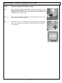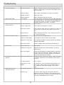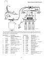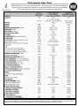
1
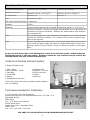
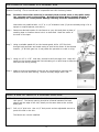
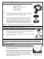
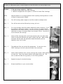
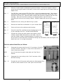
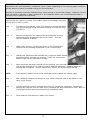
Multipure
Drinking Water Systems
Installation, Operation and Maintenance Manual
Multipure Aqua RO System
Warning
Please read manual carefully before proceeding with installation. Your failure to follow any attached instructions or
operating parameters may lead to the product’s failure and possible damage to property.
Save Manual for future reference.
System Tested and certified by NSF International against NSF/ANSI Standards 42, 53, and 58 for the reduction of claims
specified on performance data sheet.
Multipure Drinking Water Systems · 7251 Cathedral Rock Drive · Las Vegas, NV 89128
800.622.9206 · www.multipure.com · [email protected]
Thank you for your purchase of a Multipure Reverse Osmosis system. With proper
installation and maintenance, this system will provide you with high quality water for
years to come. All of Multipure’s water treatment products are rigorously tested by
independent laboratories for safety and performance. If you have any questions or concerns, please contact our customer service department at 800.622.9206 or email
[email protected].
Table of Contents
Operational Parameters
3
Contents of Reverse Osmosis System
3
Tools Recommended for Installation
3
Drill a Hole for the Faucet in a Porcelain Sink
4
Punch a Hole for the Faucet in a Stainless Steel Sink
4
Faucet Installation
5
Adapta Valve Installation
6
Reverse Osmosis Module Mounting
6
Drain Saddle Installation
7
Tank Valve Installation
7
Clear Tube Installation
8
Blue Tube Installation
8
Black Tube Installation
8
Red Tube Installation
8
MP750SI Final Filter Installation
9-11
Green Tube Installation
11
Start up Instructions
12
6 Month System Maintenance
13-14
Annual Maintenance
15-16
Membrane Maintenance
17
Check Air Pressure in the Tank
18
Trouble Shooting
19
Warranty
20
Diagram and Parts List for 5 Stage Reverse Osmosis
21
Performance Data Sheet / California Certification
22-26
Service Record
27
2
Operational Parameters
Operating Temperatures:
Maximum 100ºF (37.8ºC)
Minimum 40ºF (4.4ºC)
Operating Pressure:
Maximum 100 psi (7.43 g/cm2)
Minimum 40 psi (2.8 kg/cm2)
pH Parameters:
Maximum 11
Minimum 3
Iron:
Maximum 0.2 ppm
TDS (Total Dissolved Solids) < 1800 ppm
Turbidity:
<5NTU
Hardness:
Recommended hardness not to exceed 10 grains per gallon, or 171 mg/L of
hardness as CaCO3. System will operate with hardness over 10 grains but the
membrane life may be shortened. Addition of a water softener may lengthen
the membrane life.
The operating pressure in your home should be tested over a 24 hour period
to attain the maximum pressure. If it is above 100 psi then a pressure regulator will be required.
Note:
Note:
Reverse Osmosis water should not be run through copper tubing as the purity
of the water will leach copper and cause an objectionable taste in water and
cause pin holes to form in tubing. Be sure to follow any state or local regulations
Do not use with water that is microbiologically unsafe or of unknown quality, without adequate
disinfection before or after the system. Systems certified for cyst reduction may be used on disinfected waters that may contain filterable cysts.
Contents of Reverse Osmosis System
5 Stage RO System has:
1
1
1
1
1
1
Tank - White
RO Membrane - White
Parts Bag
Faucet Bag
Manual
Nitrate/Nitrite test strip
1
2
1
1
1
sediment filter
pre-filters, 5 micron
MP750 post filter
bracket
hand tool
If any of the items are missing, please contact Multipure
prior to installing.
Tools Recommended for Installation
1 1/4” Hole saw bit for faucet opening
Round knock-out punch for Stainless Steel sinks, 1/2” and 1 1/4”
Adjustable Wrench
Sharp Knife
1/2” - 5/8” Open end wrenches
Phillips screw driver
Needle nose pliers - Adjustable Pliers
Electric Drill
1/8”, 1/4”, 7/16” and 1” Drill bits
SEE PAGE 21 FOR AN INSTALLATION OVERVIEW AND PARTS LIST.
3
Drill a Hole for the Faucet in a Porcelain Sink
A dripping or gurgling sound may be heard coming from the Air Gap hole in the faucet and drain when the
system is running. This is normal and in compliance with UPC Plumbing Codes.
Note:
Porcelain sink surface material is extremely hard and can crack or chip quite easily.
Use extreme caution when drilling. Multipure Drinking Water Systems accepts no
responsibility for consequential damage resulting from the installation of faucet.
Most sinks are predrilled with 1 1/2” or 1 1/4” diameter holes (if you are already using it for a
sprayer or soap dispenser, see step 1).
Step 1
Determine desired location for the faucet on your sink and place a piece of
masking tape on location where hole is to be drilled. Mark the center of
the hole on the tape.
Step 2
Using a variable speed drill on the lowest speed, drill a 1/8” Pilot hole
through both porcelain and metal casing of sink at the center of the desired
location. (If drill bit gets hot, it may cause the porcelain to crack or chip).
Step 3
Using a 1.00” or 1.25” hole saw, proceed to drill the large hole. Keep drill
speed on the slowest speed and use lubricating oil or liquid soap to keep the
hole saw cool during cutting.
Step 4
Make sure the surroundings of the sink are cooled before mounting the
faucet to the sink after drilling. Remove all sharp edges with a file.
Punch a Hole for Faucet in a Stainless Steel Sink
NOTE:
If mounting faucet to a Stainless Steel Sink, you will need a 1/2” and 1 1/4”
Hole punch. The faucet opening should be centered between the back
splash and the edge of the sink, ideally on the same side as the vertical
drain pipe.
Step 5
Drill a 1/4” pilot hole. Use a 1/2” Hole punch and an adjustable wrench to
punch the hole in the sink.
The faucet can now be installed.
4
Installing the Reverse Osmosis Faucet
NOTE:
The Reverse Osmosis Models come with an air gap faucet. To install, you will need a 1/8”, 7/16”
and 1” drill bits. Minimum mounting hole size: 1.00”; Maximum mounting hole size: 1.25”.
Maximum torque on toggle bolt: 5lb.in.
Proceed as follows:
Step 6
Follow the instructions for drilling a hole in your
sink (Steps 1 through 5)
Step 7
Gather and identify the faucet components.
Step 8
Remove the faucet base (with tubing attached) and
faucet spout from their respective plastic bags. From
above the sink, feed the faucet tubing and toggle bolt
down through the 1.00” to 1.25” mounting hole in the
sink. Ensure that the soft rubber gasket is uniformly
positioned between the base and the top of the sink.
Step 9
Align the faucet base so that the handle is on the right
side and the base is sitting flush on the sink top. Turn
the handle down (towards you) to the ON position to
reveal the tightening screw (located where the spout will
be inserted). Using a phillips head screwdriver, turn the
screw clockwise until the toggle bolt secures the faucet
base snug onto the sink top. Do not over-torque toggle
bolt (5lb.in max).
Spout
Operating lever /
faucet handle
Faucet base
Toggle bolt
Black rubber
gasket
Black Tubing
Blue Tubing
Red Tubing
Step 10 Once the faucet base is securely fastened to the sink top,
insert the faucet spout into the faucet base until it is fully
seated. Turn the handle up (away from you) to the OFF
position.
Step 11 TUBING CONNECTONS:
NOTE: Do not cut any tubing at this time. Proceed with
tubing installations when you get to the pages noted
below.
The spout can be
removed by just
pulling it up and out.
It is kept in place by
two o-rings that create the water seal.
Blue Tube from the faucet should be connected to the MP750SI
Final Filter as shown on page 9.
Red Tube from the faucet should be connected to the waste
water output port on the RO system as shown on page 8.
Black Tube from the faucet should be connected to the drain
as shown on page 8.
Use screwdriver to tighten
the toggle bolt which holds
the faucet to the sink or
countertop.
faucet base
toggle bolt
5
Adapta Valve Installation -- Item #23 on page 21
Step 12
Turn off the cold water supply to the faucet by turning the angle stop valve completely off.
Step 13 Attach adapta valve as illustrated in the three photos to the right, choosing the configuration
(3/8” or 1/2”) that fits your plumbing. (When attaching the adapta valve to straight pipe threads, use
Teflon tape on the threads).
CAUTION: Water supply line to the system must be from the cold water supply line. Hot water will
severely damage your system.
1/2” slip joint nut
1/2” slip joint nut
Adapta Valve
1/2” configuration
riser
riser
1/2” slip joint nut
3/8” or 1/2” slip joint nut
Adapta Valve
3/8” configuration
riser
3/8” slip joint nut
angle stop valve
angle stop valve
Water supply line
before installation
A.
Water supply line with
Adapta Valve in 3/8” configuration
angle stop valve
B.
Water supply line with
Adapta Valve in 1/2” configuration
Reverse Osmosis Module Mounting
Step 14
Determine best location for the RO module to be mounted to allow for
future system maintenance. The parts bag has 2 self tapping screws
(#27). Using a phillips screwdriver, screw them into the cabinet wall 10
3/4” apart and 16” from the bottom of the cabinet.
NOTE:
Do not cut any tubing at this time.
6
Drain Saddle Installation
Step 15
Gather the pieces of the drain saddle (#30)
1 Black compression nut
1 Semi-circle bracket with opening
2 Screws
1 Foam washer/gasket
2 Nuts for screws
1 Semi-circle bracket
Step 16
The small square black foam gasket with a circle cut out of the middle must be applied to the inside of the drain saddle. Remove sticky
tape backing and stick to the drain saddle as shown.
Step 17
Drill a 1/4” hole through the drain pipe at least 1 1/2” above the nut
of the P-trap to allow for the removal of the P-trap, if necessary.
Assemble the drain saddle around the drain pipe. Position the drain
saddle over the drilled hole in pipe. Insert screw driver into pipe.
Using Phillips screw driver, tighten screws evenly and securely on
both sides of the drain saddle. Attach black compression nut, but do
not tighten at this time. The black tubing will be installed later.
CAUTION:
Do not over tighten the screws. It may crack the drain saddle.
Tank Valve Installation - Item #21 on page 21
Shut-off Valve
Step 18
Teflon tape must be applied on the fitting on the top of the tank in a clockwise direction. Wrap (4 - 7 turns) around the male pipe threads (MPT) on
the Stainless Steel fitting on top of the tank.
Step 19
Connect the shut-off valve (#21) (supplied in the parts bag) to the threaded
fitting on the top of tank.
Tank fitting
Tubing Connections
Note: Do not cut tubes until you get to those steps. Remove caps, if any, from tubes before
cutting tubes. Use wire cutters or sharp knife to make straight square cut. Do not use scissors.
Clear Tube Connection
Step 20
Cut 4"-6" from the clear ¼" tubing. Insert the end of this small sec
tion of tubing into the shut-off valve previously connected to the tank.
Insert the other end of the tubing into the middle port of the ¼" x ¼"
x ¼" tee connector (MC445).
20a The tubing must be fully inserted in the connector fitting; it is recommended that you measure and mark the end of the tubing that you are
inserting in the fitting to assure that it is inserted as far as it will go.
The 1/4” tubing should be inserted about 5/8”. Push the tubing
Instructions for installing the
through the small hole in the connector until you feel resistance. At
remaining
clear tubing can be
this point, the tubing is not fully inserted. Then push firmly until the
found on page 10, step 32.
tubing is inserted as far as it will go.
7
Blue Tube Connection
Step 21
21a
Position the tank in the desired location. Stand it upright or lay it
on its side (using the black plastic stand) (#31). Measure the blue
tube from the RO module over to the tank and cut to length. Insert
the blue tubing into either side of the ¼" x ¼" x ¼" tee connector
closest to the RO module.
The tubing must be fully inserted in the connector fitting; it is recommended that you measure and mark the end of the tubing that you
are inserting in the fitting to assure that it is inserted as far as it will
go. The 1/4” tubing should be inserted about 5/8”. Push the tubing
through the small hole in the connector until you feel resistance. At
this point, the tubing is not fully inserted. Then push firmly until the
tubing is inserted as far as it will go.
Faucet Tube Connection
For the Blue and Clear Faucet Tube Connection instructions follow the MP750SI Installation instructions.
Blue
NOTE:
To connect the 1/4" Blue Tube from the faucet, and the 1/4" Clear
Tube from the tank, see MP750SI Final Filter Installation. Do not
connect the faucet tubing until you get to that step.
Black Tube Connection from Faucet
NOTE:
The tubing must be as SHORT and STRAIGHT as possible, making
a downward slope from the faucet to drain saddle to allow for proper
drainage.
Step 22
Measure the black tube from faucet to the black drain saddle and
make a straight cut with a sharp knife through tube. Do not use
scissors.
Step 23
Remove black plastic nut from drain saddle. Slip black tube through
black nut. Insert black tube into the opening in the drain saddle and
tighten the black nut securely.
NOTE:
This is a gravity fed line, if there is any bend in the tube, the rinse water will not flow into the
drain properly. Water will back up and come out the air gap hole in the side of the faucet base.
Red Tube Connection from Faucet
Step 24
Using the white plastic union (#16) in the parts bag, determine
where the red tubing from the faucet and the black tubing from
the RO membrane housing would join together comfortably. Using
a knife, cut the tubes leaving a straight cut on both tubes. Insert
both red tubes in either end of the white plastic union. Use a 5/8"
wrench to tighten both of the white plastic nuts securely.
8
MP750SI Final Filter Installation -
Item #1 on page 21
The filter cartridge is shipped outside the unit housing to protect your filter cartridge and housing from
damage during shipping. Be sure to insert the filter cartridge into the Final Filter housing before installing
it. Complete, detailed instructions are provided with the filter cartridge.
Step 25
Gather the parts needed to install the MP750SI Final Filter:
1 housing
1 CB6 filter
2 1/4" male connector (MC720)
Male Connectors
Outlet
V-Band
Step 26a Connect the 1/4" male connector to the OUTLET opening on the unit housing by turning clockwise. Tighten by hand and then give one to two extra
turns with a wrench.
26b Connect 1/4" male connector to the INLET opening on the unit housing by
turning clockwise. Tighten by hand and then give one to two extra turns
with a wrench.
Step 27
Step 28a
Inlet
Filter
Turn to
connect
Remove plastic wrapper and instruction wrapper from the filter cartridge.
With the Final Filter housing in an upright position, open the unit by
unscrewing the knob on the Locking V-Band. Spread it apart and remove
the Locking V-Band.
O Ring
Separate the unit, leaving the black O-ring in place.
28b
Screw the filter cartridge into the housing top by turning the cartridge until firm. DO NOT
OVERTIGHTEN.
28c
Connect the housing top with bottom and replace Locking V-Band; replace black knob and
turn until tight. Be sure that the Locking V-Band is fastened tightly by checking it to be sure
that it is secured evenly around the housing top and bottom, and hand-tighten the
black knob until it is as tight as possible.
Faucet Blue Tube Connection
Step 29a
Insert the blue tubing from the faucet into the 1/4” outlet
connector -- insert into the hole in the connector as far as it will go.
Note: First, confirm that the tubing has a straight square cut.
Outlet
29b
The tubing must be fully inserted in the connector fitting; it is
recommended that you measure and mark the end of the tubing that
you are inserting in the fitting to assure that it is inserted as far as it
will go. The 1/4” tubing should be inserted about 7/8”.
29c
Push the tubing through the small hole in the connector until you feel
resistance. At this point, the tubing is not fully inserted. Then push firmly until
the tubing is inserted as far as it will go. See measurements above.
9
Inlet
MP750SI Installation - continued
Step 30
Connect the loose green tubing to the adapta valve (installed at steps 12 and 13).
30a
Insert the green tube into the 1/4” connector on the adapta valve. The
tubing must be fully inserted in the connector. The 1/4” tubing should
be inserted about 5/8”. Push the tubing through the small hole in the
connector until you feel resistance. At this point, the tubing is not fully
inserted. Then push firmly until the tubing is inserted as far as it will go.
DO NOT CUT GREEN TUBING.
30b
For the purpose of flushing the MP750SI Final Filter, insert the other
end of the green tube into the 1/4” inlet connector of MP750SI.
Step 31a
3/8”
configuration
To flush the Final Filter, turn on cold water supply by turning the handle
on the valve.
31b
Then open the RO faucet by lowering the operating lever (handle) and
lock in the down position.
31c
Allow water to flow through the MP750SI Final Filter for about 5 minutes
so that all air can escape.
31d
Close the RO faucet and check for leaks.
- Check the V-Band to confirm that it is secured evenly around the housing top and bottom.
- Hand-tighten the black knob on the V-Band until it is as tight possible.
31e
Allow water to again run through the unit to waste for approximately 20 minutes to charge
the carbon and flush out loose carbon particles.
31f
Shut off the water to the faucet and water supply at the valve.
31g
Disconnect the green tube from the inlet port of the MP750SI. Instructions on connecting the green tube to the RO Pre-Filter module are provided on page 11, step 35. Wait until
you get to that step to make that connection.
1/2”
configuration
NOW YOU ARE READY TO CONNECT THE FINAL FILTER TO THE TANK.
Clear Tube Connection
Step 32a
32b
NOTE:
To connect the MP750SI Final Filter to the Tank, use about 12” TO 18” of the 1/4” clear
tubing. Make sure that both ends are cut straight.
Insert one end of the clear tube into the 1/4” inlet connector as far as it will go. The
tubing must be fully inserted in the connector. The 1/4” tubing should be inserted about
5/8”. Push the tubing through the small hole in the connector until you feel resistance. At
this point, the tubing is not fully inserted. Then push firmly until the tubing is inserted as f
far as it will go.
Retain the remaining clear tubing for flushing the RO pre-filters at page 11, step 36 when
you get to that step.
10
MP750SI Installation - Connecting to the Tank
Step 33
Insert the other end of the clear tube to the 1/4” tee connection at the
tank. The tubing must be fully inserted into the tee. The 1/4” tubing
should be inserted about 5/8”. Push the tubing through the small hole
in the tee until you feel resistance. At this point, the tubing is not fully
inserted. Then push firmly until the tubing is inserted as ffar as it will
go.
Green Tube Connection
IN Connector
Step 34
Drape the green tube connected to the adapta-valve (previously
installed - see page 6 & 10) over to the "IN" side of the RO PreFilter module, leaving a gentle curve in the tubing. DO NOT
SHORTEN THE GREEN TUBE. You will need the full length of the
green tube for flushing the MP750SI Final Filter for future filter
changes.
Step 35
Insert the green tube into the 1/4” connector on the “IN” side of
the RO Pre-filter module. The tubing must be fully inserted in the
connector. The 1/4” tubing should be inserted about 5/8”. Push
the tubing through the small hole in the connector until you feel
resistance. At this point, the tubing is not fully inserted. Then push
firmly until the tubing is inserted as far as it will go.
OUTConnector
Flush the RO Module Pre-Filters
Step 36
Insert remaining clear tubing into ¼" connector on "OUT" side of the RO Pre-Filter module.
Drape the other end of the clear tubing up to the sink drain, or to a large bucket.
Step 37
To flush the RO pre-filters, turn on the cold water supply by turning the handle of the valve
counter-clockwise.
Step 38
Allow the water to run through to waste for approximately 5 minutes. Then, Shut off the water
at the valve by turning the handle clockwise until it stops.
Step 39
Disconnect the clear tubing from the "OUT" side port on the RO
Pre-filter module. To disconnect the tubing, first ensure that the
system is depressurized. Then, push in the collet against the face
of the fitting. With the collet held in this position, the tubing can
be removed. The fitting can then be reused.
NOTE:
Retain the clear tubing for flushing the RO pre-filters in the future.
Step 40
Attach the green tubing from the automatic shut-off valve (Item #22) to the “out” connector of the RO Pre-filter module. The tubing must be fully inserted in the connector. The 1/4”
tubing should be inserted about 5/8”. Push the tubing through the small hole in the connector
until you feel resistance. At this point, the tubing is not fully inserted. Then push firmly until
the tubing is inserted as far as it will go.
11
Start-Up Instructions
NOTE:
If your system is hooked up to an Ice Maker, turn Ice Maker off until tank has filled, then
flushed and refilled before allowing water to flow to Ice Maker. The system should have a
ball valve installed before the Ice Maker so it can be closed to prevent water flowing to the
Ice Maker. Your tank must be allowed to fill up in order for the unit to shut off. (If you are
installing an Ice Maker kit, tee off after the final filter).
Step
1
Turn on the incoming cold water. Turn tank valve to “on” position. Check the system for
leaks and tighten any fitting as necessary. (Check over the next 24 hours to ensure no
leaks are present).
Step
2
Open the RO faucet and leave open until after water begins to trickle out. This will take
several minutes. It will come out slowly. Then close the RO faucet.
Step
3
The tank will take between 4 to 6 hours to fill completely, depending on the size of the
membrane, local water temperature and pressure. There is an average of 5 gallons of reject
water for every 1 gallon of filtered water produced.
Step
4
Then fill the RO tank again. Now you may use your RO system for all of your drinking
water needs.
Step
5
Inspect the reverse osmosis system periodically to ensure the unit is functioning properly.
12
6 Month System Maintenance
For filters or replacement parts, contact Multipure at 800.622.9208 or at www.multipure.com
Items
Needed
1
2
1
1
Ten inch sediment filter (CBC110)
Ten inch carbon prefilters (CBC112)
Bucket to catch water from filter housings
Hand tool shipped with the system or wrench to loosen filter housings.
NOTE:
Keep RO Module in an upright position while replacing housing bottom in order
to keep O-rings properly seated.
Step
1
Turn off incoming water supply to the RO at needle on adapta valve.
Step
2
Turn off the valve at the RO tank by turning 1/4 turn.
Step
3
For more leverage, leave RO module attached to wall of cabinet. If you
are unable to access the module, you may remove it to change filters.
Starting with the closest housing, remove the housing bottom, using the
hand tool to loosen, and empty water, then discard filters. Continue on
to the 2nd and 3rd housings.
Step
4
Clean all filter housings with a mild soap solution and rinse with water.
Check O-rings and lubricate with water soluble lubricant. Water based
lubricants can be used, but petroleum based lubricants (such as
Vaseline) must not be used.
Step
5
The sediment filter has a cloth-like appearance. It must be in the
FIRST housing on the left (where the water inlet connects).
Step
6
Carbon block prefilters have a mesh covering and a white rubber gasket
on each end. Insert the carbon prefilter with gasket facing up. Be
sure to seat the black O-ring properly in the housing bottom.
Step
7
Repeat this step for the third housing.
Step
8
Discard used filters in your normal refuse.
13
6 Month System Maintenance - continued
IMPORTANT:Follow steps 9, 10 and 11 to flush carbon particles from prefilters so as not to clog the flow
restrictor which could then foul the membrane.
Step
9
After changing pre-filters, disconnect the green tube at the “out”
side port of the RO pre-filter module. See page 11, step 39 for
instructions on how to disconnect tubing.
Step
10
Use the clear tubing fromthe original installation and flush out all
carbon particles from the carbon prefilters. (Refer to page 11,
steps 36 - 39 for flushing instructions.) As soon as the water runs
clear, turn off the incoming water and re-attach the green tube
between the “out” connector of the RO Pre-filter module and the
automatic shut-off valve (Item #22).
Step
11
Turn on the incoming cold water. Check the system for leaks and
tighten any fitting as necessary. (Check over the next 24 hours to
ensure no leaks are present).
Step
12
Open the valve on the RO faucet tank.
NOTE:
Retain the clear tubing for flushing the RO pre-filters in the future.
Inspect the reverse osmosis system periodically to ensure the unit is functioning properly.
Nitrate/Nitrite Testing
The RO system is acceptable for treatment of influent concentrations of no more than 27 mg/L
nitrate and 3 mg/L nitrite in combination measured as N and is certified for nitrate/nitrite reduction
only for water supplies with a pressure of 280 kPa (40 psig) or greater.
It is recommended that user’s water be sampled and tested for nitrate/nitrite at least once a year to
confirm that the RO system is performing its function.
Included in this shipment is a nitrate/nitrite test strip. Within one year of installation of the RO
System you should test your water. Just dip the strip in the treated water, following the instructions
included with the test strip.
If the levels of nitrate or nitrite exceed the influent concentrations shown above, the RO membrane
should be replaced.
14
Annual Maintenance
For filters or replacement parts, contact Multipure at 800.622.9208 or at www.multipure.com
Step
1
Perform 6 month system maintenance (previous section). Ensure the system is depressurized by turning the valve on the tank 1/4 turn until it stops and turn off water supply at
adapta valve.
Step
2
The CB6 filter (used in the MP750 Final Filter) should be replaced annually. See replacement filter wrap for additional instructions on replacing the CB6 carbon block filter in the
MP750SI Final Filter unit. Remove plastic wrapper and instruction wrapper from the filter
cartridge. With the Final Filter housing in an upright position, open the unit by
unscrewing the knob on the Locking V-Band. Spread it apart and remove the Locking VBand.
Step
3
Separate the unit, leaving the black O-ring in place.
Step
4
Remove the used filter and discard it in your normal refuse.
Step
5
Clean and rinse out the stainless steel housing.
Step
6
Screw the new filter cartridge into the housing top by turning the cartridge until firm. DO NOT OVERTIGHTEN.
Step
7
Connect the housing top with bottom and replace Locking
V-Band; replace black knob and turn until tight. Be sure
that the Locking V-Band is fastened tightly by checking it to
be sure that it is secured evenly around the housing top and bottom, and hand-tighten the
black knob until it is as tight as possible.
Remove Filter
Connect Filter
Flush the carbon block filter, as follows:
Step
8
NOTE:
Disconnect the green tube from the “in” connector of the RO
Pre-filter module. See page 11, step 39 for instructions on
how to disconnect tubing.
IN Connector
You will reconnect the green tube after the Final Filter is
flushed.
Step
9
Disconnect the clear tubing to the “inlet” connector of the
MP750SI housing.
Step
10
Connect the end of the green tubing that you disconnected from
the RO Pre-filter module to the “inlet” port of the MP750SI.
15
INLET port
OUTConnector
Annual Maintenance - continued
Step
11a
To flush the Final Filter, turn on cold water supply by turning the handle on the shut-off
valve and/or adapta valve / valve.
11b
Then open the RO faucet by turning the operating lever (handle) and lock in the down
position.
11c
Allow water to flow through the MP750SI Final Filter for about 5 minutes so that all air can
escape.
11d
Close the RO faucet and check for leaks.
- Check the V-Band to confirm that it is secured evenly around the housing top and bottom.
- Hand-tighten the black knob on the V-Band until it is as tight as possible
Step
12
Allow water to again run through the unit to waste for approximately 20 minutes to charge
the carbon and flush out loose carbon particles.
Step
13
Shut off the water at the valve / adapta valve.
Step
14
Disconnect the green tube from the MP750SI. See page 11, step 39 for instructions on
how to disconnect tubing.
NOW RECONNECT THE FINAL FILTER TO THE TANK.
NOTE: Be sure to fully insert the tubing in the connector. Push the tubing through the small hole in the
connector until you feel resistance. At this point, the tubing is not fully inserted. Then push firmly until
the tubing is inserted as far as it will go.
Step
15
Insert the end of the clear tube back into the 1/4” “inlet” connector on the MP750SI.
RECONNECT THE GREEN TUBING TO THE RO Module.
NOTE: Be sure to fully insert the tubing in the connector. Push the tubing through the small hole in the
connector until you feel resistance. At this point, the tubing is not fully inserted. Then push firmly until
the tubing is inserted as far as it will go.
Step
16
Insert the green tube back into the 1/4” “in” connector of the RO Pre-filter module.
RESTART SYSTEM.
Step
17
Turn on the incoming cold water. Check the system for leaks and tighten any fittings as
necessary. (Check over the next 24 hours to ensure no leaks are present).
Step
18
Open the tank valve by turning the handle 1/4 turn. Open the RO faucet and leave open
until after water begins to trickle out. Then close the RO faucet.
Step
19
Now you may continue using your RO system for all of your drinking water needs.
Inspect the reverse osmosis system periodically to ensure the unit is functioning properly.
16
Membrane Maintenance
Membranes have a life expectancy of between 2 and 3 years, depending on the incoming water conditions
and the amount of water processed through the RO membrane.
Normally, a membrane would be replaced during a semi-annual or annual filter change. However, if at any
time you notice a reduction in water production or an unpleasant taste in the reverse osmosis water, it
could be time to replace the membrane.
Depressurize the system by turning off the water supply at the adapta valve and
turning valve on tank 1/4 turn.
Step
1
To change the membrane, use a 5/8” wrench to remove the Green
tube on the left side of the membrane housing (the end with only
one elbow).
Step
2
Remove the cap from the white horizontal membrane housing.
Use the hand tool shipped with the unit to loosen. Turn cap
counter-clockwise to loosen.
Step
3
Using a pair of pliers, grip and pull firmly on the membrane to
remove from the housing and discard in your normal refuse.
Step
4
Unwrap new membrane and lubricate the o-rings with water soluble
lubrication before inserting into housing. Insert end with the two
black O-rings into the membrane housing.
Step
5
Once membrane has been inserted into the housing, you must take
your thumbs and give a firm push to properly seat the membrane. Replace membrane
housing cap and tighten. Use the hand tool to tighten, but do not OVERTIGHTEN.
NOTE:
To be properly seated, the tip of the membrane must be below the housing edge.
Step
6
After replacing membrane housing into clips, attach the green tube to the elbow on cap
using a 5/8” wrench.
Step
7
The flow restrictor must be changed each time you change the membrane. Replace the
existing flow restrictor with the new one by removing the white compression nuts. Be sure
to orientate the flow with the arrow pointing toward the faucet.
Step
8
Follow Start Up instructions to restart your system.
17
Maintenance - Check Air Pressure in the Tank
NOTE:
Check air pressure when tank is empty
Step
1
Using a digital air gauge, check the air pressure in the tank. You
should always have between 5-7 psi. If you have more than 7 psi,
release air and recheck. If you have less than 5 psi, add air, air can
be added with a bicycle pump.
Step
2
Your unit comes with a stand for your storage tank to sit on if you
need to turn the unit on its side.
Step
3
This allows for air flow under tank keeping moisture and standing
water from rusting on the bottom of your tank which would void
your warranty.
18
Trouble
Shooting
Troubleshooting
PROBLEM
1. Low/Slow Production
2. Milky colored water
CAUSE
SOLUTIONS
Low water pressure
Assure a minimum of 40 psi incoming water pressure.
Make sure water supply is turned on and Adapta valve is
all the way open
Crimps in tubing
check tubing and straighten or repair as necessary
Clogged pre-filters
replace pre-filters
Fouled membrane
replace membrane and flow restrictor.
Air in System
Air in the system is a normal occurrence with initial start
up of the RO system. This milky look will disappear during normal use within 1-2 weeks. If condition reoccurs
after filter changes, drain tank 1 to 2 times.
See #1 above
3. Water constantly running/ unit Low water pressure
will not shut off
Crimp in supply tube
4. Noise from faucet or drain
5. Faucet leaks
High water pressure
Check incoming water pressure to make sure it does not
exceed 80 psi. A pressure relief valve may be necessary.
High pressure in
Air gap faucet
Empty storage tank of water. Set tank air pressure to 5
psi. See previous page.
Inherent sound with air-gap faucets
Location of drain saddle
See diagram for proper location of drain saddle.
Restriction in drain tube
Clear blockage sometimes caused by debris from garbage
disposal or dishwasher.
High water pressure
Pressure regulator required if pressure exceeds 80 psi
Crimp in drain line
Check tubing.
Restriction in drain line
Straighten all drain lines. Clear blockage. Cut off any
excess tubing.
Drain tube clogged
Caused from dishwasher or garbage disposal. Disconnect
the 3/8” black line at the drain, clean the 3/8” black line
out with a wire, then reconnect. Blowing air through the
line will not always remove the clog.
6. Small amount of water in stor- System just starting up
age tank
7. Water leaks from the
white filter housing
Check tubing and straighten or repair.
Normally it takes 4-6 hours to fill tank. Note: low pressure and/or temperature can drastically reduce production rate.
Low water pressure
See # 1 above
Excessive air in tank
bladder
Tank pressure is set at the factory and should be 5 psi
when empty. Add if below 5 psi and bleed if above 5
psi. Check only when tank is empty. See previous
page.
Not properly tightened
Tighten the housing
Kinked O-ring
Turn off the water supply and release the pressure.
Replace the O-ring if necessary. Then lubricate it and
make sure the O-ring is seated in the filter housing properly before reinstalling the filter housing.
19
Product Guarantee and Warranty
Multipure 90-Day Guarantee: Multipure demonstrates its confidence in the performance of
its Drinking Water Systems by offering its 90 day money-back guarantee. If you should find
the Drinking Water System unsatisfactory, let us know within thirty days of purchase, and we
will promptly exchange it or refund your money.
Multipure Warranty: Multipure warrants to the original retail customer its Reverse Osmosis
Drinking Water Systems and components to be free of defects in material and workmanship
for use under normal care, and will repair or replace any System at no charge (excluding
transportation to Multipure headquarters) to the customer during the warranty period. The
Housings are warranted for a lifetime (provided that filter has been changed at least once per
year). All exterior hoses and attachments to the System are also warranted for defects in
material and workmanship for one year.
Multipure Filters and RO membrane are warranted for defects in material and workmanship
for use under normal care. The life of the filter cartridges depends upon the amount of impurities in the water to be processed. For optimum performance, it is essential that the filter
cartridges and membrane be replaced as specified herein or when they have processed the
listed capacity, whichever comes first.
Limitations and Exclusions
Except as otherwise expressly provided above, Multipure makes no warranties, express or
implied, arising by law or otherwise, including without limitation the implied warranties of
merchantability and fitness for a particular purpose, to any person. This limited warranty
may not be altered, varied or extended except by a written instrument executed by Multipure.
The remedy of repair or replacement as provided under this limited warranty is exclusive. In
no event shall Multipure Corporation be liable for any consequential or incidental damages to
any person whether occasioned by negligence of the manufacturer, including without limitation damages of loss of use, cost of substitution, property damage, or other monetary loss.
Warranty is valid only if Drinking Water System is operated within conditions listed herein.
What this warranty does not cover: This warranty does not cover defects resulting from
improper installation, (contrary to Multipure’s written instructions), from abuse, misuse,
misapplication, improper maintenance, neglect, alteration accidents, casualties, fire, flood,
freezing, environmental factors, water pressure spikes or other such acts of God.
This warranty will be void if defects occur due to failure to observe the following conditions:
1.
2.
3.
4.
5.
6.
7.
8.
The Reverse Osmosis System must be hooked up to a potable municipal or well cold
water supply.
The hardness of the water should not exceed 10 grains per gallon, or 171 mg/L.
Maximum incoming iron must be less than 0.2 ppm.
The pH of the water must not be lower than 3 or higher than 11.
The incoming water pressure must be between 40 and 100 pounds per square inch.
Incoming water to the RO cannot exceed 100 degrees F (40 degrees C).
Incoming TDS (Total Dissolved Solids) not to exceed 1800 ppm.
Do not use with water that is microbiologically unsafe or of unknown quality or without
adequate disinfection before or after the system. Systems certified for cyst reduction
may be used on disinfected waters that my contain filterable cysts.
20
Multipure Model No. MP750 Plus RO
8
Blue
Blue
Green
Green
Red
Blue
Out
In
Black
13
13
Red
1
Green
Clear
Multipure MP750 Plus RO
17
38
Clear
21
Clear
15
15
Blue
Green
Rev 1304
The reverse osmosis system contains a replaceable treatment component (Item #4), critical for the
effective reduction of total dissolved solids. The product water should be tested periodically to verify
that the system is performing properly.
Item# Part #
1
MP750SI/CB6
2
3
4
5
6
7
CBC110
CBC112
CB-ROM
MCL10
MCB10
MC950
8
9
10
11
12
13
14
15
16
17
18
19
MC3R03LRC
MC246W
N/A
N/A
MC932B
MC720
MC935W
MC741
MC937W
MC445
MC142
MC210
Description
Final Filter Carbon Block
Submicron / CB6 Replacement
Cartridge
Sediment pre-filter
Carbon Block 5 micron pre-filter
RO Membrane
Housing Lid - 1/4” white
Housing Bottom 10” white
Membrane Housing vessel includes o’ring
RO Faucet, tubing attached, chrome
RO tank - 3 gallon - white
Nut, 1/4” black
Inlet/Outlet Connector 1/4”
Elbow, 1/4 x 1/8” - white
Adapter, 1/4 x 1/4”
Union, 1/4 x 1/4”
tee 1/4 x 1/4 x 1/4
Delrin sleeve
Brass insert
21
Item#
20
21
22
23
24
25
26
27
28
29
30
31
32
33
34
35
36
37
38
39
Part #
MC171
MC1884
MC939B
MC920LF
MC935W
MC933
MC221
MC941
MC940
n/a
MC942
MC946
MC943
n/a
MC239
MC236
MC237
MC238
MC232RH
MC006
40
D452
Description
Hex nipple 1/4” brass
Shut off valve
Valve shut off 1/4”
Adapta valve
Elbow, 1/4 x 1/8” - white
Bracket, (4SV)
Screw, wood
Bracket screw, 1” - self tapping
Membrane clip
omitted intentionally
Drain saddle 3/8”
Tank stand
O’ring for Housing #6
omitted intentionally
Green Tubing
Black Tubing
Blue Tubing
Red Tubing
Clear Tubing
Hand tool for RO module and prefilters (not shown)
Nitrate/Nitrite test strip (not
shown)
Performance Data Sheet
Multipure Model No. MP750 Plus RO Drinking Water Systems have been tested and certified under
NSF Standard Nos. 42, 53 and 58 as shown below. The concentration of the indicated substances
in water entering the system was reduced to a concentration less than or equal to the permissible
limit for water leaving the system, as specified in NSF/ANSI 53, Health Effects.
** Percent reduction reflects actual performance of Multipure product as specifically tested (at 200% of capacity). Percent reduction shown for
VOCs* reflects the allowable claims for Volatile Organic Chemicals/Compounds as per Tables. Chloroform was used as a surrogate for VOC
reduction claims; the Multipure Systems actual reduction rate of Chloroform was >99.8% as tested (at 200% capacity).
NSF/ANSI 42 - Aesthetic Effects
The System has been tested according to NSF/ANSI Standard 42 for the reduction of the following substances. The concentration of the indicated substances in water entering the system was reduced to a concentration less than or equal to
the permissible limit for water leaving the system.
23
NSF/ANSI 58 - Reverse Osmosis
The System has been tested according to NSF/ANSI Standard 58 for the reduction of the following substances. The concentration of the indicated substances in water entering the system was reduced to a concentration less than or equal to the permissible limit for water leaving the system, as specified in NSF/ANSI 58.
NOTES:
1. Multipure Drinking Water Systems have been certified, as indicated, by NSF International for compliance to NSF/ANSI Standard
Nos. 42 and 53, and 58.
2. This Multipure Drinking Water System(s) have been certified by the State of California Department of Health Services for the
reduction of specific contaminants listed herein.
3. Chloroform was used as a surrogate for claims of reduction of Volatile Organic Chemicals (VOC). Multipure Systems tested at
>99.8% actual reduction of Chloroform. Percent reduction shown herein reflects the allowable claims for VOCs as per tables in the
Standard.
4. Do not use with water that is microbiologically unsafe or with water of unknown quality without adequate disinfection
before or after the unit. Systems certified for cyst reduction may be used on disinfected waters that may contain filterable cysts.
5. The System may be used with municipal or well water sources that are treated and tested on a regular basis to ensure bacteriological safe quality of the water.
6. Do not allow water to freeze in the unit. If unit is exposed to freezing temperatures, drain water from unit and remove filters.
7. Do not allow the RO membrane to dry out. If the RO system is to sit for an extended period of time, remove the RO membrane,
place in a zip lock plastic baggie with a small amount of RO water, and place in the refrigerator until it is time to restart the RO
system. The RO membrane can become damaged if allowed to dry out.
8. Multipure Drinking Water System Housings are warranted for a lifetime (provided that filter has been changed at least once per
year). All exterior hoses and attachments to the System are warranted for defects in material and workmanship for one year. Please
see the Owner’s Manual for complete product guarantee and warranty information.
9. Please see the Owner’s Manual for installation instructions and operating procedures.
10. In compliance with New York law, it is recommended that before purchasing a water treatment system, NY residents have their water
supply tested to determine their actual water treatment needs. Please compare the capabilities of the Multipure unit with your actual
water treatment needs.
11. Check for compliance with state and local laws and regulations.
12. While testing was performed under standard laboratory conditions, actual performance may vary.
13. The list of substances which the treatment device reduces does not necessarily mean that these substances are present in your
tap water.
14. This system is acceptable for treatment of influent concentrations of no more than 27 mg/L nitrate and 3 mg/L nitrite in combination
measured as N and is certified for nitrate/nitrite reduction only for water supplies with a pressure of 280 kPa (40 psig) or greater.
15. This system has been tested for the treatment of water containing pentavalent arsenic (also known as As(V), As(+5), or arsenate)
at concentrations of 0.050 mg/l or less. This system reduces pentavalent arsenic, but may not remove other forms of arsenic.
This system is to be used on water supplies containing a detectable free chlorine residual at the system inlet or on water supplies
that have been demonstrated to contain only pentavalent arsenic. Treatment with chloramine (combined chlorine) is not sufficient to
ensure complete conversion of trivalent arsenic to pentavalent arsenic. Please see the Arsenic Facts section of the Performance
Data Sheet for further information.
24
Replacement Filters and Parts
Filter life will vary in proportion to the amount of water used and the level of impurities in the water being processed.
Replacement filters, membrane, and parts can be purchased directly from Multipure Corporation. Replacement filter model
numbers are shown below.
To dispose of the used filter or membrane, remove it from the housing and place the old filter or membrane in your normal
refuse. Carbon filters disposed of in a normal landfill will not release any chemical contamination but will probably continue
to adsorb additional contaminants that are disposed of in landfills.
MP750 Plus RO Operation and Maintenance Specifications
Depending on water chemistry, water temperature, and water pressure, the MP750 Plus RO System production and performance will vary. Refer to Owner’s Manual for further maintenance requirements and warranty information.
Note: This Performance Data Sheet addresses the U.S. Environmental Protection Agency (USEPA) Primary and Secondary Drinking
Water Regulations in effect at its time of publication, as they related to Multipure's performance in conformance to the industry performance criteria. These regulations are continually being updated at the Federal level. Accordingly, this list of MCLs will be reviewed and
amended when appropriate. Please see sales brochure for list of product certifications.
25
California Department of Public Health
Certification / Registration
Facts About Arsenic (in compliance with NSF
Standard 58)
Arsenic (abbreviated As) is a naturally occurring
contaminant found in many ground waters.
Arsenic in water has no color, taste or odor. It
must be measured by a lab test. Public water utilities must have their water tested for arsenic. You
can get the results from your water utility. If you
have your own well, you can have the water tested. The local health department or the state environmental health agency can provide a list of certified labs. The cost is typically $15 to $30.
Information about arsenic in water can be found on
the Internet at the US Environmental Protection
Agency website:
www.epa.gov/safewater/arsenic.html.
There are two forms of arsenic: pentavalent
arsenic (also called As(V), As(+5), and arsenate)
and trivalent arsenic (also called As(III), As(+3),
and arsenite). In well water, arsenic may be pentavalent, trivalent, or a combination of both.
Special sampling procedures are needed for a lab
to determine what type and how much of each type
of arsenic is in the water. Check with the labs in
your area to see if they can provide this type of
service.
Reverse Osmosis (RO) systems are very effective
at removing pentavalent arsenic. However, RO
systems do not remove trivalent arsenic from water
very well. A free chlorine residual will rapidly convert trivalent arsenic to pentavalent arsenic. Other
water treatment chemicals such as ozone and
potassium permanganate will also change trivalent
arsenic to pentavalent arsenic. A combined chlorine residual (also called chloramine) may not convert all the trivalent arsenic. If you get your water
from a public water utility, contact the utility to find
out if free chlorine or combined chlorine is used in
the water system.
The Multipure MP750 Plus RO is designed to
remove only pentavalent arsenic. It will not convert
trivalent arsenic to pentavalent arsenic.
This treatment system was tested in a laboratory to
remove pentavalent arsenic. Under lab conditions,
as defined in NSF/ANSI Standard 58, the system
reduced 0.050 mg/l (ppm) pentavalent arsenic to
0.010 mg/l (ppm) (the USEPA standard for drinking
water) or less. The performance of the system
may be different at your installation. Have the
treated water tested for arsenic to check if the system is working properly.
The RO component of the Multipure MP750 Plus
RO system must be replaced as indicated in the
Owner's Manual to ensure the system will continue
to remove arsenic and other contaminants. The
component identification and locations where you
can purchase the component are listed in the
installation/operation manual.
Multipure International
7251 Cathedral Rock Drive
Las Vegas, NV 89128
800.622.9206 · 702.360.8880
[email protected]
www.multipure.com
26
Thank you for choosing a Multipure Drinking Water System.
Be sure to replace your filters and RO membrane on a regularly scheduled basis.
To order a Replacement Filters
call 800.622.9208
or
www.multipure.com
Service Record
Date
1st stage sediment 2nd stage carbon 3rd stage carbon Final carbon filter
(6 months)
(6 months)
(6 months)
(1 year)
Multipure
7251 Cathedral Rock Drive
Las Vegas, NV 89128
800.622.9206 toll-free
702.360.8880 phone
702.360.8575 fax
[email protected]
F508RO/1403
TFM Membrane
(2-3 years)