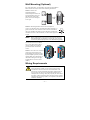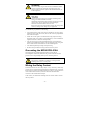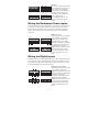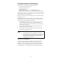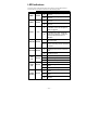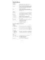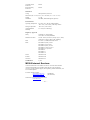
1
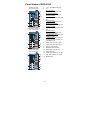
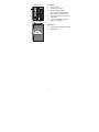
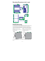
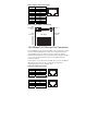
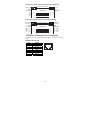
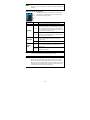
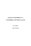
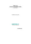
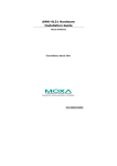
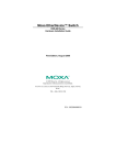
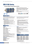
MOXA EtherDevice™ Switch
EDS-510A Series Hardware Installation Guide
First Edition, September 2006
Moxa Networking Co., Ltd.
Tel: +886-2-2910-1230
Fax: +886-2-2910-1231
www.moxa.com
[email protected] (Worldwide)
[email protected] (The Americas)
P/N: 1802005100000
Package Checklist
The EDS-510A is shipped with the following items. If any of these items are
missing or damaged, please contact your customer service representative for
assistance.
y 1 EDS-510A EtherDevice Switch
y Hardware Installation Guide (this guide)
y CD-ROM with user’s manual and Windows utility
y Moxa product warranty statement
y RJ45 to DB9 console port cable
y Protective caps for unused ports
y DIN-Rail mounting kit (attached to the EDS-510A’s rear panel by default)
Optional Accessories
y SFP-1GSXLC: Small Form factor Pluggable transceiver with 1000BaseSX,
LC, 0.5km, 0 to 60°C
y SFP-1GSXLC-T: Small Form factor Pluggable transceiver with
1000BaseSX, LC, 0.5km, -40 to 75°C
y SFP-1GLXLC: Small Form factor Pluggable transceiver with 1000BaseLX,
LC, 10km, 0 to 60°C
y SFP-1GLXLC-T: Small Form factor Pluggable transceiver with
1000BaseLX, LC, 10km, -40 to 75°C
y SFP-1GLHXLC: Small Form factor Pluggable transceiver with
1000BaseLHX, LC, 40 km, 0 to 60°C
y SFP-1GLHXLC-T: Small Form factor Pluggable transceiver with
1000BaseLHX, LC, 40 km, -40 to 75°C
y SFP-1GZXLC: Small Form factor Pluggable transceiver with 1000BaseZX,
80 km, LC, 0 to 60°C
y ABC-01: Automatic Backup Configurator via RS-232 Console Port, 0 to
60°C
y DR-4524—DIN-Rail Power Supply (24 VDC, 45W/2A, with 85 to 264
VAC input)
y DR-75-24—DIN-Rail Power Supply (24 VDC, 75W/3.2A, with 85 to 264
VAC input)
y DR-120-24—DIN-Rail Power Supply (24 VDC, 120W/5A, with 88 to 132
VAC/176 to 264 VAC input by switch)
y EDS-SNMP OPC Server Pro—CD with EDS-SNMP OPC Server
software and user’s manual
y WK-46—Wall Mounting Kit (will be shipped with the product)
— 1 —
Panel Views of EDS-510A
1.
2.
EDS-510A-3GT
Front Panel View
6
7
8
9
10
1
5
4
3
2
1
11
12
14
13
EDS-510A-1GT2SFP
Front Panel View
4.
6
7
8
9
10
1
5
4
3
2
11
12
1
13
14
3.
5.
1 to 7: 10/100BaseT(X) port
G1:
EDS-510A-3GT
10/100/1000BaseT(X) port
EDS-510A-1GT2SFP
10/100/1000BaseT(X) port
EDS-510A-3SFP
1000BaseSX/LX/LHX/ZX port
G2:
EDS-510A-3GT
10/100/1000BaseT(X) port
EDS-510A-1GT2SFP
1000BaseSX/LX/LHX/ZX port
EDS-510A-3SFP
1000BaseSX/LX/LHX/ZX port
G3:
EDS-510A-3GT
10/100/1000BaseT(X) port
EDS-510A-1GT2SFP
1000BaseSX/LX/LHX/ZX port
EDS-510A-3SFP
1000BaseSX/LX/LHX/ZX port
G1, G2, G3: LED indicators for
1000 Mbps ports
6.
PWR1: LED for power input 1
7.
PWR2: LED for power input 2
8.
FAULT: LED indicator
9.
MASTER: LED indicator
10. COUPLER: LED indicator
EDS-510A-3SFP
Front Panel View
11. Turbo Ring logo
12. 100M: LED indicator for TP port
5
4
3
2
6
7
8
9
10
1
1
11
12
14
13
13. 10M: LED indicator for TP port
14. Model Name
— 2 —
Top Panel:
Top Panel View
1.
Ground screw
2.
RS-232 console port
5
3.
4.
6
5.
Heat dissipation orifices
DIP switches for Ring Master,
Ring Coupler, and Turbo Ring
6-pin terminal block for DI 1, DI 2,
and PWR 2
6-pin terminal block for PWR1,
Relay 1, and Relay 2
1
RS-232 CONSOLE
V2PWR2
V2+
2
DI1
I1
DI2
I2
3
RELAY1
1
2
3
4
4
OFF
------
RELAY2
MASTER
COUPLER
TURBO
RING
ON
V1+
PWR1
V1-
6.
Rear Panel View
2
7
1
Rear Panel:
7.
Screw holes for Wall Mounting Kit
8.
DIN-Rail Kit
8
7
— 3 —
Mounting Dimensions (unit = mm)
15.0
30.00
51.3
9.00
13.9
135.00
135.00
35.00
DlN-Rail
DlN-Rail Kit
Front View
105.00
Side View
3.5
6
57.05
66.80
24.3
6
55
7.5
46.77
7.5
27.20
48.30
39.37
10
10
5
7.75
24.56
DlN-Rail Kit
13.9
30.50
18.2
7.75
13.9
80.2
Rear View
Wall Mounting Kit
DIN-Rail Mounting
The aluminum DIN-Rail attachment plate should already be fixed to the back
panel of the EDS-510A when you take it out of the box. If you need to
reattach the DIN-Rail attachment plate to the EDS-510A, make sure the stiff
metal spring is situated towards the top, as shown by the following figures.
STEP 1—Insert the top of the
DIN-Rail into the slot just below the
stiff metal spring.
STEP 2—The DIN-Rail attachment
unit will snap into place as shown in
the following illustration.
metal
spring
metal
spring
DIN-Rail
DIN-Rail
To remove the EDS-510A from the DIN-Rail, simply reverse Steps 1 and 2
above.
— 4 —
Wall Mounting (Optional)
For some applications, you will find it convenient to mount MOXA
EDS-510A on the wall, as shown in the following illustrations:
STEP 1—Remove the
aluminum DIN-Rail
attachment plate from the rear
panel of the EDS-510A, and
then attach the wall mount
plates, as shown in the figure
at the right.
Ö
STEP 2—Mounting the EDS-510A on the wall requires 4
6.0 mm
screws. Use the EDS-510A, with wall mount plates attached, as a
guide to mark the correct locations of the 4 screws. The heads of
the screws should be less than 6.0 mm in diameter, and the shafts
should be less than 3.5 mm in diameter, as shown in the figure on 3.5 mm
at right.
NOTE
Before tightening the screws into the wall, make sure the screw
head and shank size are suitable by inserting the screw through
one of the keyhole-shaped apertures of the Wall Mounting Plates.
Do not screw the screws in all the
way—leave about 2 mm to allow
room for sliding the wall mount
panel between the wall and the
screws.
STEP 3—Once the screws are fixed
to the wall, insert the four screw
heads through the wide parts of the
keyhole-shaped apertures, and then
slide the EDS-510A downwards, as
indicated in the figure at the right.
Tighten the four screws for more
stability.
Wiring Requirements
WARNING
Do not disconnect modules or wires unless power has been
switched off or the area is known to be non-hazardous. The
devices may only be connected to the supply voltage shown on
the type plate. The devices are designed for operation with a
Safety Extra-Low Voltage. Thus, they may only be connected to
the supply voltage connections and to the signal contact with the
Safety Extra-Low Voltages (SELV) in compliance with IEC950/
EN60950/ VDE0805.
— 5 —
ATTENTION
This unit is a built-in type. When the unit is installed in another
piece of equipment, the equipment enclosing the unit must
comply with fire enclosure regulation IEC 60950/EN60950 (or
similar regulation).
ATTENTION
Safety First!
Be sure to disconnect the power cord before installing and/or
wiring your MOXA EtherDevice Switch.
Calculate the maximum possible current in each power wire and
common wire. Observe all electrical codes dictating the
maximum current allowable for each wire size.
If the current goes above the maximum ratings, the wiring could
overheat, causing serious damage to your equipment.
You should also pay attention to the following:
y Use separate paths to route wiring for power and devices. If power wiring
and device wiring paths must cross, make sure the wires are perpendicular
at the intersection point
y NOTE: Do not run signal or communications wiring and power wiring
through the same wire conduit. To avoid interference, wires with different
signal characteristics should be routed separately
y You can use the type of signal transmitted through a wire to determine
which wires should be kept separate. The rule of thumb is that wiring that
shares similar electrical characteristics can be bundled together
y You should separate input wiring from output wiring
y We advise that you label the wiring to all devices in the system.
Grounding the MOXA EDS-510A
Grounding and wire routing help limit the effects of noise due to
electromagnetic interference (EMI). Run the ground connection from the
ground screw to the grounding surface prior to connecting devices.
ATTENTION
This product is intended to be mounted to a well-grounded
mounting surface such as a metal panel.
Wiring the Relay Contact
The EDS-510A has two sets of relay outputs—relay 1 and relay 2. Each relay
contact uses two contacts of the terminal block on the EDS-510A’s top panel.
Refer to the next section for detailed instructions on how to connect the wires
to the terminal block connector, and how to attach the terminal block
connector to the terminal block receptor.
In this section, we illustrate the meaning of the two contacts used to connect
the relay contact.
— 6 —
RELAY1
RELAY2
RELAY1
RELAY2
FAULT:
The two sets of relay contacts of the
6-pin terminal block connector are
used to detect user-configured
events. The two wires attached to
the fault contacts form an open
circuit when a user-configured
event is triggered. If a
user-configured event does not
occur, the fault circuit remains
closed.
Wiring the Redundant Power Inputs
The EDS-510A has two sets of power inputs—power input 1 and power input
2. The top two contacts and the bottom two contacts of the 6-pin terminal
block connector on the EDS-510A’s top panel are used for the two digital
inputs. The top and front views of one of the terminal block connectors are
shown here.
V2- V2+
V1- V1+
PWR2
PWR1
V2- V2+
V1- V1+
PWR2
PWR1
STEP 1: Insert the
negative/positive DC wires into the
V-/V+ terminals, respectively.
STEP 2: To keep the DC wires
from pulling loose, use a small
flat-blade screwdriver to tighten the
wire-clamp screws on the front of
the terminal block connector.
STEP 3: Insert the plastic terminal
block connector prongs into the
terminal block receptor, which is
located on the EDS-510A’s top
panel.
Wiring the Digital Inputs
The EDS-510A has two sets of digital inputs, DI 1 and DI 2. Each DI consists
of two contacts of the 6-pin terminal block connector on the EDS-510A’s top
panel, which are used for the two DC inputs. The top and front views of one
of the terminal block connectors are shown here.
I1
DI1
I1
DI1
I2
DI2
I2
D I2
STEP 1: Insert the negative
(ground)/positive DI wires into the
┴/I1 terminals, respectively.
STEP 2: To keep the DI wires from
pulling loose, use a small flat-blade
screwdriver to tighten the
wire-clamp screws on the front of
the terminal block connector.
STEP 3: Insert the plastic terminal
block connector prongs into the
terminal block receptor, which is
located on the EDS-510A’s top
panel.
— 7 —
Communication Connections
Each EDS-510A switch has 3 types of communication port:
y 1 RJ45 console port (RS-232 interface)
y 7 10/100BaseTX Ethernet ports
y 3 gigabit Ethernet ports:
3 10/100/1000BaseTX ports, or 1 10/100/1000BaseTX and 2
1000BaseSFP (mini-GBIC) ports, or 3 1000BaseSFP (mini-GBIC) ports
In this section, we present two types of diagrams—Pinout Diagrams and Cable
Wiring Diagrams—that convey information about the ports and the cables used
to connect the EDS-510A to other devices:
Pinouts—The “Pinouts” diagrams display the type of signal passing through
each of the port’s pins.
Cable Wiring—The “Cable Wiring” diagrams present standard cable wiring
schemes for cables used to connect the EDS-510A’s ports to other devices.
These diagrams display three pieces of information:
1.
2.
3.
When building your own cable, refer to the “pin-to-pin” cable wiring
information displayed between the two vertical dashed lines to see
which pin of the connector on the left should be connected to which pin
of the connector on the right.
The information to the left of the left vertical dashed lines gives the
pinouts of the relevant EDS-510A port.
The information to the right of the right vertical dashed line gives the
pinouts of the opposing device’s port.
NOTE
1.
2.
The pin numbers for male DB9 connectors and hole numbers
for female DB9 connectors are labeled on the connector.
The pin numbers for 10-pin RJ45 connectors (and ports) are
typically not labeled on the connector (or port). Refer to the
following Pinout and Cable Wiring diagrams to see how
10-pin RJ45 pins are numbered
RS-232 Connection
The EDS-510A has one RS-232 (10-pin RJ45) console port, located on the
top panel. Use either an RJ45-to-DB9 (see the cable following wiring
diagrams) to connect the EDS-510A’s console port to your PC’s COM port.
You may then use a console terminal program, such as MOXA PComm
Terminal Emulator, to access the EDS-510A’s console configuration utility.
— 8 —
RJ45 (10-pin) Console Port Pinouts
Pin
1
2
3
4
5
6
7
8
9
10
Description
-----DSR
-----GND
TxD
RxD
GND
-----DTR
------
1
10
RJ45 (10-pin) to DB9 (F) Cable Wiring
Moxa
EtherDevice
Server
COM Port
RJ45 Plug Pin 1
RJ45
Connector
Female DB9
Connector
Cable Wiring
1
DCD
2
DSR
3
RTS
GND 4/7
5
TxD
6
RxD
8
CTS
9
DTR
1
6
7
5
3
2
8
4
DCD
DTR
CTS
GND
RxD
TxD
RTS
DSR
10/100BaseT(X) Ethernet Port Connection
The 10/100BaseT(X) ports located on the EDS-510A’s front panel are used to
connect to Ethernet-enabled devices. Most users configure these ports for
Auto MDI/MDI-X mode, in which case the port’s pinouts are adjusted
automatically depending on the type of Ethernet cable used (straight-through
or cross-over), and the type of device (NIC-type or HUB/Switch-type)
connected to the port.
In what follows, we give pinouts for both MDI (NIC-type) ports and MDI-X
(HUB/Switch-type) ports. We also give cable wiring diagrams for
straight-through and cross-over Ethernet cables.
RJ45 (8-pin, MDI) Port Pinouts
Pin
1
2
3
6
Signal
Tx+
TxRx+
Rx-
1
8
1
8
RJ45 (8-pin, MDI-X) Port Pinouts
Pin
1
2
3
6
Signal
Rx+
RxTx+
Tx-
— 9 —
RJ45 (8-pin) to RJ45 (8-pin) Straight-through Cable Wiring
Straight-Through Cable
Switch Port
RJ45
Connector
Tx+
TxRx+
Rx-
NIC Port
RJ45 Plug Pin 1
RJ45
Connector
Cable Wiring
3
6
1
2
3
6
1
2
Rx+
RxTx+
Tx-
RJ45 (8-pin) to RJ45 (8-pin) Cross-over Cable Wiring
Cross-Over Cable
Switch Port
(NIC Port)
RJ45 Plug Pin 1
RJ45
Connector
(Rx+)
(Rx-)
(Tx+)
(Tx-)
Tx+
TxRx+
Rx-
Switch Port
(NIC Port)
RJ45
Connector
Cable Wiring
3
6
1
2
1
2
3
6
Rx+
RxTx+
Tx-
(Tx+)
(Tx-)
(Rx+)
(Rx-)
1000BaseT Ethernet Port Connection
1000BaseT data is transmitted on differential TRD+/- signal pairs over copper
wires.
MDI/MDI-X Port Pinouts
Pin
1
2
3
4
5
6
7
8
Signal
TRD(0)+
TRD(0)TRD(1)+
TRD(2)+
TRD(2)TRD(1)TRD(3)+
TRD(3)-
1
— 10 —
8
1000BaseSFP (mini-GBIC) Fiber Port
The gigabit Ethernet ports on the EDS-510A-1GT2SFP and EDS-510A-3SFP
are 1000BaseSFP Fiber ports, which require using the gigabit mini-GBIC
fiber transceivers to work properly. MOXA provides completed transceiver
models for different distance requirement.
Multi mode:
y 1000BaseSX
0 to 500 m, 850 nm (50/125 μm, 400 MHz*km)
0 to 275 m, 850 nm (62.5/125 μm, 200 MHz*km)
y 1000BaseLX
0 to 1100 m, 1310 nm (50/125 μm, 800 MHz*km)
0 to 550 m, 1310 nm (62.5.125 μm, 500 MHz*km)
Single mode:
y 1000BaseLX
0 to 10 km, 1310 nm (9/125 μm, 3.5 PS/(nm*km))
y 1000BaseLHX
0 to 40 km, 1310 nm (9/125 μm, 3.5 PS/(nm*km))
y 1000BaseZX
0 to 80 km, 1550 nm (9/125 μm, 19 PS/(nm*km))
The concept behind the LC port and cable is quite straightforward. Suppose
that you are connecting devices I and II; contrary to electrical signals, optical
signals do not require a circuit in order to transmit data. Consequently, one of
the optical lines is used to transmit data from device I to device II, and the
other optical line is used transmit data from device II to device I, for
full-duplex transmission.
Remember to connect the Tx (transmit) port of device I to the Rx (receive)
port of device II, and the Rx (receive) port of device I to the Tx (transmit)
port of device II. If you make your own cable, we suggest labeling the two
sides of the same line with the same letter (A-to-A and B-to-B, as shown
below, or A1-to-A2 and B1-to-B2).
LC-Port Pinouts
LC-Port to LC-Port Cable Wiring
A
A
Tx
B
B
Cable Wiring
Rx
A
B
A
B
Turbo Ring DIP Switch Settings
EDS-510A series are plug-and-play managed redundant Ethernet switches. The
proprietary Turbo Ring protocol was developed by MOXA to provide better
network reliability and faster recovery time. MOXA Turbo Ring’s recovery
time is less than 300 ms-compared to a 3- to 5-minute recovery time for
commercial switches-decreasing the possible loss caused by network failures in
an industrial setting. There are 4 Hardware DIP Switches for Turbo Ring on the
top panel of EDS-510A that can be used to set up the Turbo Ring easily within
seconds.
— 11 —
NOTE
If you do not want to use a hardware DIP switch to set up the Turbo
Ring, you can use a web browser, Telnet, or console to disable this
function.
EDS-510A Series DIP Switches
1
------
2
MASTER
3
COUPLER
4
TURBO
RING
DIP Switch
------
The default setting for each DIP Switch is OFF. The
following table explains the effect of setting the DIP
Switches to the ON positions.
Setting
ON
Enables the EDS-510A to be the Ring Master in a
Turbo Ring topology, and enables the Turbo Ring
break warning. If the EDS-510A is the Master of
this Turbo Ring, and the Turbo Ring is broken, the
relay will form an open circuit.
OFF
Disables the EDS-510A from being the Ring
Master in a Turbo Ring topology, and disables the
Turbo Ring break warning.
ON
Enables the Turbo Ring Coupling function. Use
port 5 and 6 of EDS-510A to form the Ring
Coupler path.
OFF
Disables the Turbo Ring coupling function.
ON
Enables plug-and-play Turbo Ring redundancy.
Ports 7 and 8 of EDS-510A are used to form a
Turbo Ring.
OFF
Disables the plug-and-play Turbo Ring
redundancy function.
MASTER
COUPLER
TURBO
RING
Description
Serves no function (reserved for future use).
NOTE
You must enable the Turbo Ring function first before using the DIP
switch to activate the Master and Coupler functions.
NOTE
If you do not enable any of the EDS-510A switches to be the Ring
Master, the Turbo Ring protocol will automatically choose the
EDS-510A with the smallest MAC address range to be the Ring
Master. If you accidentally enable more than one EDS-510A to be
the Ring Master, these EDS-510A switches will auto-negotiate to
determine which one will be the Ring Master.
— 12 —
LED Indicators
The front panel of the MOXA EDS-510A contains several LED indicators.
The function of each LED is described in the following table:
LED
Color
PWR1
AMBER
State
On
PWR2
FAULT
MASTER
Off
Power is not being supplied to power
input P1.
On
Power is being supplied to power
input P2.
Off
Power is not being supplied to power
input P2.
On
When the corresponding PORT alarm
is enabled, and a user-configured
event is triggered.
Off
When the corresponding PORT alarm
is enabled and a user-configured
event is not triggered, or when the
corresponding PORT alarm is
disabled.
On
When the EDS-510A is the Master of
this Turbo Ring
AMBER
RED
GREEN
When the EDS-510A is Ring Master
Blinking of this Turbo Ring and the Turbo Ring
is broken.
On
When the EDS-510A enables the
coupling function to form a back-up
path.
Off
When the EDS-510A disables the
coupling function.
COUPLER GREEN
10M
(TP)
100M
(TP)
1000M
(TP/SFP)
Description
Power is being supplied to power
input P1.
On
TP port’s 10 Mbps link is active.
GREEN Blinking Data is being transmitted at 10 Mbps.
Off
TP port’s 10 Mbps link is inactive.
On
TP port’s 100 Mbps link is active.
GREEN Blinking Data is being transmitted at 100
Mbps.
Off
TP port’s 100 Mbps link is inactive.
On
TP/SFP port’s 1000 Mbps link is
active.
GREEN Blinking Data is being transmitted at 1000
Mbps.
Off
TP/SFP port’s 1000 Mbps link is
inactive.
— 13 —
Specifications
Technology
Standards
IEEE802.3, 802.3u, 802.3x, 802.1D, 802.1w,
802.1Q, 802.1p, 802.1X, 802.3ad, 802.3z
Protocols
IGMP V1/ V2/ V3 device, GMRP, GVRP, SNMP
V1/V2c/V3, DHCP Server/Client, BootP, TFTP,
SNTP, SMTP, RARP, RMON and EDS-SNMP
OPC Server Pro (optional)
MIB
MIB-II, Ethernet-like MIB, P-BRIDGE MIB,
Q-BRIDGE MIB, Bridge MIB, RSTP MIB, RMON
MIB Group 1,2,3,9
Interface
RJ45 Ports
10/100/1000BaseT(X) auto negotiation speed, F/H
duplex mode, and auto MDI/MDI-X connection
Fiber Ports
optional 1000BaseSX/LX/LHX/ZX (LC connector)
Console Port
RS-232 (10-pin RJ45)
LED Indicators
PWR1, PWR2, FAULT, 10/100M (TP port),
1000M, Ring Master and Ring Coupler
Alarm Contact
Two relay outputs with current carrying capacity of
1A @ 24 VDC
Digital Input
Two inputs with the same ground, but electrically
isolated from the electronics
• For state “1”: +13 to +30V
• For state “0”: -30 to +3V
• Max. input current: 8 mA
Optical Fiber—1000BaseSX/LX/LHX/ZX
Distance:
Multi mode:
y 1000BaseSX
0 to 500 m, 850 nm (50/125 µm, 400 MHz*km)
0 to 275 m, 850 nm (62.5/125 µm, 200 MHz*km)
y 1000BaseLX
0 to 1100 m, 1310 nm (50/125 µm, 800 MHz*km)
0 to 550 m, 1310 nm (62.5.125 µm, 500 MHz*km)
Single mode:
y 1000BaseLX
0 to 10 km, 1310 nm (9/125 µm, 3.5 PS/(nm*km))
y 1000BaseLHX
0 to 40 km, 1310 nm (9/125 µm, 3.5 PS/(nm*km))
y 1000BaseZX
0 to 80 km, 1550 nm (9/125 µm, 19 PS/(nm*km))
Power
Input Voltage
24 VDC (12 to 45 VDC), redundant inputs
Input Current (@24V)
0.47A: (EDS-510A-3GT)
0.38A: (EDS-510A-1GT2SFP)
0.34A: (EDS-510A-3SFP)
Connection
Two removable 6-pin terminal blocks
— 14 —
Overload Current
Protection
Present
Reverse Polarity
Protection
Present
Mechanical
Casing
IP30 protection, metal case
Dimensions (W × H × D) 80.5 × 135 × 105 mm (3.17 × 5.31 × 4.13 in)
Weight
1.17 kg
Installation
DIN-Rail, Wall Mounting Kit (optional)
Environmental
Operating Temperature
0 to 60°C (32 to 140°F), standard models
-40 to 75°C (-40 to 185°F), wide temp. models
Storage Temperature
-40 to 85°C (-40 to 185°F)
Ambient Relative
Humidity
5 to 95% (non-condensing)
Regulatory Approvals
Safety
UL60950, UL 508 (pending),
CSA C22.2 No. 60950, EN60950
Hazardous Location
UL/cUL Class I, Division 2, Groups A, B, C, and D,
ATEX Class I, Zone 2, EEx nC IIC (Pending)
EMI
FCC Part 15, CISPR (EN55022) class A
EMS
EN61000-4-2 (ESD), Level 3
EN61000-4-3 (RS), Level 3
EN61000-4-4 (EFT), Level 2
EN61000-4-5 (Surge), Level 3
EN61000-4-6 (CS), Level 3
EN61000-4-8
EN61000-4-11
EN61000-4-12
Shock
IEC60068-2-27
Freefall
IEC60068-2-32
Vibration
IEC60068-2-6
WARRANTY
5 years
MOXA Internet Services
Customer satisfaction is our number one concern. To ensure that customers
receive the full benefit of our products, Moxa has set up on-line support
services to provide technical support, driver updates, product information, and
user’s manual updates.
E-mail for technical support:
[email protected]
[email protected]
Website for up-to-date product information:
www.moxa.com
— 15 —
(Worldwide)
(The Americas)