1
Part No. OS3-304
MTR-90III
MASTER TAPE RECORDER
OPERATION AND MAINTENANCE MANUAL
FOURTH EDITION
Printed: September 1996
Ed. 4 (GK)
Copyright © 1990, 1991, 1992, 1996 Otari, Inc.
Printed in Japan
This manual may not be reproduced by any means without written permission.
CAUTION
To prevent fire or shock hazard:
Do not expose this unit to rain or moisture.
Do not remove panels (unless instructed to do so).
There are no user-serviceable parts inside.
Refer servicing to qualified service personnel.
PLEASE READ THROUGH THE SAFETY INSTRUCTIONS ON THE NEXT PAGE.
SAFETY INSTRUCTIONS
1.
Read Instructions
All safety and operating instructions should be read before the device is
operated.
2.
Retain Instructions
The safety and operating instructions should be retained for future reference.
3.
Heed Warnings
All warnings on the device and in the operating instructions should be
complied with.
4.
Follow Instructions
All operating and use instructions should be followed.
5.
Water and Moisture
The device should not be used near water — for example, near a bathtub,
wash bowl, sink, laundry tub, in a wet basement, near a swimming pool, etc.
6.
Carts and Stands
The device should be used only with a cart or stand that is recommended by
the manufacturer.
7.
Ventilation
The device should be situated so that its location or position does not interfere
with its proper ventilation. For example, the device should not be situated on a
bed, sofa, rug, or similar surface that may block the ventilation openings; or,
placed in a built-in installation, such as a bookcase or cabinet that may impede
the flow of air through the ventilation openings.
8.
Heat
The device should be situated away from heat sources such as a radiator,
heat register, stove or other appliances (including amplifiers) that produce
heat.
9.
Power Sources
The device should be connected to a power supply only of the type described
in the operating instructions or as marked on the device.
10.
Grounding or Polarization
Precautions should be taken so that the grounding or polarization means of
the device is not defeated.
11.
Power Cord Protection
Power supply cords should be routed so that they are not likely to be walked
on or pinched by items placed upon or against them, paying particular
attention to cords at plugs, convenience receptacles, and the point where
they exit from the device.
12.
Cleaning
The device should be cleaned only as recommended by the manufacturer.
13.
Non-Use Periods
The power cord of the device should be unplugged from the outlet when left
unused for a long period of time.
14
Object and Liquid Entry
Care should be taken that objects do not enter and that liquids are not spilled
into the enclosure through openings.
15.
Damage Requiring Service
The device should be serviced by qualified service personnel when:
A. The power supply cord or the plug has been damaged; or
B. Objects have entered, or liquid has been spilled into the appliance; or
C. The appliance has been exposed to rain; or
D. The appliance does not appear to operate normally or exhibits a marked
change in performance; or
E. The appliance has been dropped, or the enclosure damaged.
16.
Servicing
The user should not attempt to service the device beyond what is described
in the operating instructions. All other service should be referred to qualified
personnel.
COMMUNICATION WITH OTARI
FOR SERVICE INFORMATION AND PARTS
All Otari products are manufactured under strict quality control. Each unit is carefully inspected and tested prior to
shipment.
If, however, some adjustment or technical support becomes necessary, replacement parts are required, or technical
questions arise, please contact your Otari dealer or contact Otari at:
Otari, Inc.
4-33-3 Kokuryo-cho
Chofu-shi, Tokyo182-0022
Japan
Phone : (81) 42481-8626
Fax
: (81) 42481-8633
Otari Corporation
378 Vintage Park Drive
Foster City
California 94404
U.S.A.
Phone : (650) 341-5900
Fax
: (650) 341-7200
Otari Deutschland GmbH.
Rudolf-Diesel-Straße 12
D-40670 Meerbusch 2 (Osterath)
Germany
Phone : (49) 2159-50861
Fax
: (49) 2159-1778
Otari Singapore Pte., Ltd
40 MacTaggart Road
Singapore 1336
Phone : (65) 284-7211
Fax
: (65) 284-4727
Another part of Otari’s continuing technical support program for our products is the continuous revision of manuals as the
equipment is improved or modified. In order for you to receive the information and support which is applicable to your
equipment, and for the technical support program to function properly, please include the following information, most of
which can be obtained from the Serial number label on the machine, in all correspondence with Otari:
•
•
•
•
Model Number:
Serial Number:
Date of Purchase:
Name and address of the dealer where the machine was purchased and the power requirements (voltage and
frequency) of the machine.
Table of Contents
Safety Instructions . . . . . . . . . . . . . . . . . . . . . . . . . . . . . . . . . . . . . . . . . . . . . . . . . . . . . . . . . iv
Communication with Otari . . . . . . . . . . . . . . . . . . . . . . . . . . . . . . . . . . . . . . . . . . . . . . . . . v
Section 1 Introduction
1.1 The Otari MTR-90III Tape Recorder . . . . . . . . . . . . . . . . . . . . . . . . . . . . . 1-2
1.2 Using This Manual . . . . . . . . . . . . . . . . . . . . . . . . . . . . . . . . . . . . . . . . . . . . . . . . . 1-3
1.2.1 Organization . . . . . . . . . . . . . . . . . . . . . . . . . . . . . . . . . . . . . . . . . . . . . . . . . . . . . 1-3
1.2.2 Conventions Within This Manual . . . . . . . . . . . . . . . . . . . . . . . . . . . . . . . . . . 1-4
Section 2 Installation and Inspection
2.1 Inspection . . . . . . . . . . . . . . . . . . . . . . . . . . . . . . . . . . . . . . . . . . . . . . . . . . . . . . . . . . . 2-2
2.2 Assembly of Remote Control Unit . . . . . . . . . . . . . . . . . . . . . . . . . . . . . . . 2-6
2.3 Stand Assembly (Remote Control Unit/Auto Locator) . . . . . . . . 2-7
2.4 Connections . . . . . . . . . . . . . . . . . . . . . . . . . . . . . . . . . . . . . . . . . . . . . . . . . . . . . . . . 2-9
2.4.1
2.4.2
2.4.3
2.4.4
2.4.5
Cable Connections . . . . . . . . . . . . . . . . . . . . . . . . . . . . . . . . . . . . . . . . . . . . . . . 2-9
NR Remote Connector . . . . . . . . . . . . . . . . . . . . . . . . . . . . . . . . . . . . . . . . . . 2-11
EXT CLOCK Connector . . . . . . . . . . . . . . . . . . . . . . . . . . . . . . . . . . . . . . . . . . 2-11
Serial I/O Connector . . . . . . . . . . . . . . . . . . . . . . . . . . . . . . . . . . . . . . . . . . . . 2-12
Parallel I/O Connector . . . . . . . . . . . . . . . . . . . . . . . . . . . . . . . . . . . . . . . . . . . 2-13
2.5 Power Supply Conversion . . . . . . . . . . . . . . . . . . . . . . . . . . . . . . . . . . . . . . . 2-14
Section 3 Controls and Indicators
3.1 Transport Controls and Indicators . . . . . . . . . . . . . . . . . . . . . . . . . . . . . . . 3-2
3.2 Rear Panel . . . . . . . . . . . . . . . . . . . . . . . . . . . . . . . . . . . . . . . . . . . . . . . . . . . . . . . . . . 3-5
3.3 Remote Control Unit (CB-147) . . . . . . . . . . . . . . . . . . . . . . . . . . . . . . . . . . . 3-7
3.4 Auto Locator (CB-148) . . . . . . . . . . . . . . . . . . . . . . . . . . . . . . . . . . . . . . . . . . . 3-10
Section 4 Operation
4.1 Modes of Operation . . . . . . . . . . . . . . . . . . . . . . . . . . . . . . . . . . . . . . . . . . . . . . . . 4-2
4.2 Record and Play Modes . . . . . . . . . . . . . . . . . . . . . . . . . . . . . . . . . . . . . . . . . . . 4-3
4.2.1
4.2.2
4.2.3
4.2.4
4.2.5
4.2.6
Threading the Tape on the Machine . . . . . . . . . . . . . . . . . . . . . . . . . . . . . . .
Recording Initial Tracks . . . . . . . . . . . . . . . . . . . . . . . . . . . . . . . . . . . . . . . . . .
Playback of Initial Tracks . . . . . . . . . . . . . . . . . . . . . . . . . . . . . . . . . . . . . . . . .
Sel·Rep Recording (Overdubbing) . . . . . . . . . . . . . . . . . . . . . . . . . . . . . . . .
Sel·Rep Recording (Punch-Ins) . . . . . . . . . . . . . . . . . . . . . . . . . . . . . . . . . . .
Rehearsal of Overdubs and Punch-Ins . . . . . . . . . . . . . . . . . . . . . . . . . . . .
4.2.6.1 Rehearsal of Overdubs . . . . . . . . . . . . . . . . . . . . . . . . . . . . . . . . . . . .
4.2.6.2 Rehearsal of Punch-Ins . . . . . . . . . . . . . . . . . . . . . . . . . . . . . . . . . . . .
4.2.7 Mixdown . . . . . . . . . . . . . . . . . . . . . . . . . . . . . . . . . . . . . . . . . . . . . . . . . . . . . . . . .
4.2.8 Cue Modes . . . . . . . . . . . . . . . . . . . . . . . . . . . . . . . . . . . . . . . . . . . . . . . . . . . . . . .
4.2.8.1 Normal Cue Mode . . . . . . . . . . . . . . . . . . . . . . . . . . . . . . . . . . . . . . . . .
April 1992
4-3
4-4
4-5
4-5
4-6
4-7
4-7
4-7
4-8
4-8
4-8
vii
Table of Contents
MTR-90III Operation and Maintenance Manual
4.2.8.2 Fast Cue Mode (Lifter Defeat) . . . . . . . . . . . . . . . . . . . . . . . . . . . . . . 4-8
4.2.9 Spot Erasure . . . . . . . . . . . . . . . . . . . . . . . . . . . . . . . . . . . . . . . . . . . . . . . . . . . . . 4-9
4.2.10 Variable Speed Mode . . . . . . . . . . . . . . . . . . . . . . . . . . . . . . . . . . . . . . . . . . . . 4-9
4.2.11 External Speed Reference . . . . . . . . . . . . . . . . . . . . . . . . . . . . . . . . . . . . . . 4-10
4.3 Auto Locator Operation . . . . . . . . . . . . . . . . . . . . . . . . . . . . . . . . . . . . . . . . . . 4-10
4.3.1 Entering Locate Times . . . . . . . . . . . . . . . . . . . . . . . . . . . . . . . . . . . . . . . . . .
4.3.2 Storing Cue Points . . . . . . . . . . . . . . . . . . . . . . . . . . . . . . . . . . . . . . . . . . . . . .
4.3.3 Recalling Cue Points . . . . . . . . . . . . . . . . . . . . . . . . . . . . . . . . . . . . . . . . . . . .
4.3.4 Clearing Cue Points . . . . . . . . . . . . . . . . . . . . . . . . . . . . . . . . . . . . . . . . . . . . .
4.3.5 Search . . . . . . . . . . . . . . . . . . . . . . . . . . . . . . . . . . . . . . . . . . . . . . . . . . . . . . . . . .
4.3.6 Search Zero . . . . . . . . . . . . . . . . . . . . . . . . . . . . . . . . . . . . . . . . . . . . . . . . . . . .
4.3.7 Shuttle . . . . . . . . . . . . . . . . . . . . . . . . . . . . . . . . . . . . . . . . . . . . . . . . . . . . . . . . .
4.3.8 Auto Rewind . . . . . . . . . . . . . . . . . . . . . . . . . . . . . . . . . . . . . . . . . . . . . . . . . . . .
4.3.9 Setting the Tape Time Readout (Offset Mode) . . . . . . . . . . . . . . . . . . . .
4.3.10 Zero Set . . . . . . . . . . . . . . . . . . . . . . . . . . . . . . . . . . . . . . . . . . . . . . . . . . . . . . .
4.3.11 Stop Watch . . . . . . . . . . . . . . . . . . . . . . . . . . . . . . . . . . . . . . . . . . . . . . . . . . . .
4-10
4-11
4-11
4-12
4-12
4-13
4-14
4-14
4-15
4-15
4-15
Section 5 Maintenance
5.1 Demagnetizing and Cleaning . . . . . . . . . . . . . . . . . . . . . . . . . . . . . . . . . . . . . 5-2
5.1.1 Demagnetizing the Heads and Tape Guidance Path . . . . . . . . . . . . . . . . 5-2
5.1.2 Cleaning the Tape Path . . . . . . . . . . . . . . . . . . . . . . . . . . . . . . . . . . . . . . . . . . . 5-3
5.1.3 Cleaning the Head Shield Screw . . . . . . . . . . . . . . . . . . . . . . . . . . . . . . . . . . 5-4
5.2 Routine Maintenance . . . . . . . . . . . . . . . . . . . . . . . . . . . . . . . . . . . . . . . . . . . . . . 5-5
5.2.1
5.2.2
5.2.3
5.2.4
5.2.5
5.2.6
Removing and Reinserting the Printed Circuit Boards . . . . . . . . . . . . . .
Hour Meter . . . . . . . . . . . . . . . . . . . . . . . . . . . . . . . . . . . . . . . . . . . . . . . . . . . . . .
Reel Motor Replacement . . . . . . . . . . . . . . . . . . . . . . . . . . . . . . . . . . . . . . . . .
Brake Pad Replacement . . . . . . . . . . . . . . . . . . . . . . . . . . . . . . . . . . . . . . . . . .
VU Meter Lamp Replacement . . . . . . . . . . . . . . . . . . . . . . . . . . . . . . . . . . . . .
Head Shield Position Adjustment . . . . . . . . . . . . . . . . . . . . . . . . . . . . . . . . .
5-5
5-5
5-6
5-7
5-8
5-8
5.3 Circuit Descriptions . . . . . . . . . . . . . . . . . . . . . . . . . . . . . . . . . . . . . . . . . . . . . . . . 5-9
5.3.1
5.3.2
5.3.3
5.3.4
5.3.5
5.3.6
5.3.7
5.3.8
5.3.9
Playback Head and Preamp . . . . . . . . . . . . . . . . . . . . . . . . . . . . . . . . . . . . . . . 5-9
Speed Selection and High Frequency Playback Equalization . . . . . . . . 5-9
Low Frequency Playback Equalization . . . . . . . . . . . . . . . . . . . . . . . . . . . . . 5-9
Sync Playback . . . . . . . . . . . . . . . . . . . . . . . . . . . . . . . . . . . . . . . . . . . . . . . . . . . 5-9
Output Stage . . . . . . . . . . . . . . . . . . . . . . . . . . . . . . . . . . . . . . . . . . . . . . . . . . . 5-10
Input Circuitry . . . . . . . . . . . . . . . . . . . . . . . . . . . . . . . . . . . . . . . . . . . . . . . . . . 5-10
Audio/Bias Mixing Circuitry . . . . . . . . . . . . . . . . . . . . . . . . . . . . . . . . . . . . . . 5-11
Erase Head Driver . . . . . . . . . . . . . . . . . . . . . . . . . . . . . . . . . . . . . . . . . . . . . . . 5-11
Reel Control Board . . . . . . . . . . . . . . . . . . . . . . . . . . . . . . . . . . . . . . . . . . . . . . 5-12
Section 6 Alignment
6.1 Transport Alignment . . . . . . . . . . . . . . . . . . . . . . . . . . . . . . . . . . . . . . . . . . . . . . . 6-2
6.1.1 Transport Deck Plate . . . . . . . . . . . . . . . . . . . . . . . . . . . . . . . . . . . . . . . . . . . . . 6-2
6.1.1.1 Opening and Closing the Transport Deck . . . . . . . . . . . . . . . . . . . 6-2
6.1.1.2 Removing the Transport Deck Plate . . . . . . . . . . . . . . . . . . . . . . . . 6-3
6.1.1.3 Reinstalling the Transport Deck Plate . . . . . . . . . . . . . . . . . . . . . . 6-4
6.1.2 Head Geometry . . . . . . . . . . . . . . . . . . . . . . . . . . . . . . . . . . . . . . . . . . . . . . . . . . 6-4
6.1.2.1 Reproduce Head Azimuth . . . . . . . . . . . . . . . . . . . . . . . . . . . . . . . . . . 6-5
6.1.2.2 Record Head Azimuth . . . . . . . . . . . . . . . . . . . . . . . . . . . . . . . . . . . . . . 6-5
6.1.3 Swing Arm Travel . . . . . . . . . . . . . . . . . . . . . . . . . . . . . . . . . . . . . . . . . . . . . . . . 6-6
viii
April 1992
MTR-90III Operation and Maintenance Manual
Table of Contents
6.1.4 Fast Forward/Rewind Damping Solenoid Adjustment . . . . . . . . . . . . . . 6-7
6.1.5 Swing Arm Adjustment . . . . . . . . . . . . . . . . . . . . . . . . . . . . . . . . . . . . . . . . . . . 6-8
6.1.6 Tape Lifter Mechanism . . . . . . . . . . . . . . . . . . . . . . . . . . . . . . . . . . . . . . . . . . . 6-8
6.1.7 Brakes . . . . . . . . . . . . . . . . . . . . . . . . . . . . . . . . . . . . . . . . . . . . . . . . . . . . . . . . . . 6-10
6.1.8 Reel Turntable Height . . . . . . . . . . . . . . . . . . . . . . . . . . . . . . . . . . . . . . . . . . . 6-11
6.1.9 Reel Tension Servo Adjustments . . . . . . . . . . . . . . . . . . . . . . . . . . . . . . . . 6-12
6.1.9.1 Upper and Lower Limit Adjustment of Reel Tension . . . . . . . 6-12
6.1.9.2 Preliminary Center Position and Gain Adjustments . . . . . . . . 6-13
6.1.9.3 Tape Tension Check . . . . . . . . . . . . . . . . . . . . . . . . . . . . . . . . . . . . . . 6-13
6.1.9.4 Reel Motor Tracking with Capstan . . . . . . . . . . . . . . . . . . . . . . . . 6-14
6.1.9.5 Fine Adjustment of Position and Gain . . . . . . . . . . . . . . . . . . . . . 6-15
6.1.9.6 Reel Size Detector Adjustment . . . . . . . . . . . . . . . . . . . . . . . . . . . . 6-15
6.1.10 Capstan Servo Adjustments . . . . . . . . . . . . . . . . . . . . . . . . . . . . . . . . . . . . 6-16
6.1.10.1 Capstan Tachometer Adjustment . . . . . . . . . . . . . . . . . . . . . . . . 6-16
6.1.10.2 Adjustment of CAPSTAN CONTROL PCB Assembly . . . . . . . 6-17
6.1.10.3 Fast Wind Speed Adjustment . . . . . . . . . . . . . . . . . . . . . . . . . . . . 6-17
6.1.11 Adjustment of TRANSPORT CONTROL PCB Assembly . . . . . . . . . . 6-19
6.1.12 Adjustment of MASTER CPU PCB Assembly . . . . . . . . . . . . . . . . . . . . 6-19
6.1.13 VU Meter Calibration . . . . . . . . . . . . . . . . . . . . . . . . . . . . . . . . . . . . . . . . . . . 6-19
6.2 Audio Alignment . . . . . . . . . . . . . . . . . . . . . . . . . . . . . . . . . . . . . . . . . . . . . . . . . . 6-20
6.2.1
6.2.2
6.2.3
6.2.4
6.2.5
6.2.6
6.2.7
Reproduce Amp Alignment . . . . . . . . . . . . . . . . . . . . . . . . . . . . . . . . . . . . . .
Sync Amp Alignment . . . . . . . . . . . . . . . . . . . . . . . . . . . . . . . . . . . . . . . . . . . .
Bias Alignment . . . . . . . . . . . . . . . . . . . . . . . . . . . . . . . . . . . . . . . . . . . . . . . . . .
Record Alignment . . . . . . . . . . . . . . . . . . . . . . . . . . . . . . . . . . . . . . . . . . . . . . .
Record Phase Compensation . . . . . . . . . . . . . . . . . . . . . . . . . . . . . . . . . . . .
Erase Current Adjustment . . . . . . . . . . . . . . . . . . . . . . . . . . . . . . . . . . . . . . .
Gain Structure . . . . . . . . . . . . . . . . . . . . . . . . . . . . . . . . . . . . . . . . . . . . . . . . . .
6-20
6-21
6-21
6-22
6-23
6-24
6-24
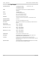
Section 7 Specifications
7.1 Tape Transport . . . . . . . . . . . . . . . . . . . . . . . . . . . . . . . . . . . . . . . . . . . . . . . . . . . . . 7-2
7.2 Electronics (Measured with AMPEX #456 Tape) . . . . . . . . . . . . . . 7-3
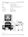
7.3 Physical . . . . . . . . . . . . . . . . . . . . . . . . . . . . . . . . . . . . . . . . . . . . . . . . . . . . . . . . . . . . . 7-4
7.4 Accessories . . . . . . . . . . . . . . . . . . . . . . . . . . . . . . . . . . . . . . . . . . . . . . . . . . . . . . . . . 7-5
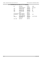
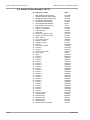
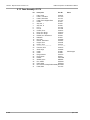
Section 8 Printed Circuit Board Layouts and Parts Lists
8.1 PB-16KA REC & REPRO Amplifier P.C.B. Assembly . . . . . . . . . . 8-2
8.2 PB-15L Bias Control P.C.B. Assembly . . . . . . . . . . . . . . . . . . . . . . . . . . . 8-5
8.3 PB-4PKA Reel Size Detect P.C.B. Assembly . . . . . . . . . . . . . . . . . . . . 8-6
8.4 PB-45MB Speed Calculate P.C.B. Assembly . . . . . . . . . . . . . . . . . . . . 8-7
8.5 PB-45R Hour Meter P.C.B. Assembly . . . . . . . . . . . . . . . . . . . . . . . . . . . 8-8
8.6 PB-46A Capstan Photo Amplifier P.C.B. Assembly . . . . . . . . . . . . 8-9
8.7 PB-45SB Reel Power TR P.C.B. Assembly . . . . . . . . . . . . . . . . . . . . 8-10
8.8 PB-45T Capstan Power TR P.C.B. Assembly . . . . . . . . . . . . . . . . . . 8-12
8.9 PB-45VA Capstan Control P.C.B. Assembly . . . . . . . . . . . . . . . . . . . 8-14
8.10 PB-47AB Transport Control P.C.B. Assembly . . . . . . . . . . . . . . . 8-17
April 1992
ix
Table of Contents
MTR-90III Operation and Maintenance Manual
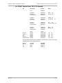
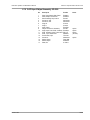
8.11 PB-4APA Master CPU P.C.B. Assembly . . . . . . . . . . . . . . . . . . . . . . 8-18
8.12 PB-45YA I/O Control P.C.B. Assembly . . . . . . . . . . . . . . . . . . . . . . . . 8-21
8.13 PB-45Z Tape Counter P.C.B. Assembly . . . . . . . . . . . . . . . . . . . . . . . 8-22
8.14 PB-4HQB Reel Control P.C.B. Assembly . . . . . . . . . . . . . . . . . . . . . 8-25
8.15 PB-62G Power P.C.B. Assembly . . . . . . . . . . . . . . . . . . . . . . . . . . . . . . 8-26
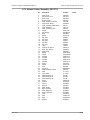
Section 9 Exploded Views and Parts Lists
9.1 Head Assembly (KH-6K) . . . . . . . . . . . . . . . . . . . . . . . . . . . . . . . . . . . . . . . . . . 9-2
9.2 Capstan(KC-6E) /CNT Roller Assembly (KI-6E) . . . . . . . . . . . . . . . . 9-5
9.3 Tape Lifter (KR-6B)/Shield Assembly (ZA-72S) . . . . . . . . . . . . . . . 9-6
9.4 Tension Arm Assembly (KA-6H) . . . . . . . . . . . . . . . . . . . . . . . . . . . . . . . . . 9-9
9.5 Reel Assembly (KW-6B) . . . . . . . . . . . . . . . . . . . . . . . . . . . . . . . . . . . . . . . . . 9-10
9.6 Motor Drive Heatsink Assembly (ZA-94Y) . . . . . . . . . . . . . . . . . . . . 9-13
9.7 Amp Chassis Assembly (A1050) . . . . . . . . . . . . . . . . . . . . . . . . . . . . . . . 9-14
9.8 Control Panel (CB-24J)/
24CH VU Meter Assembly (ZA-94Z) . . . . . . . . . . . . . . . . . . . . . . . . . . . 9-17
9.9 Control Chassis Assembly (CB-319) . . . . . . . . . . . . . . . . . . . . . . . . . . . 9-18
9.10 24CH Input/Output Assembly (ZA-95A) . . . . . . . . . . . . . . . . . . . . . 9-21
9.11 Power Supply Assembly (DS-4W) . . . . . . . . . . . . . . . . . . . . . . . . . . . . 9-22
9.11.1 Power Supply Assembly [1] . . . . . . . . . . . . . . . . . . . . . . . . . . . . . . . . . . . . 9-22
9.11.2 Power Supply Assembly [2] . . . . . . . . . . . . . . . . . . . . . . . . . . . . . . . . . . . . 9-25
9.12 Case Assembly (K1176) . . . . . . . . . . . . . . . . . . . . . . . . . . . . . . . . . . . . . . . . 9-26
9.13 Remote Control Assembly (CB-147-S) . . . . . . . . . . . . . . . . . . . . . . 9-27
9.14 Auto Locator Assembly (CB-148-S) . . . . . . . . . . . . . . . . . . . . . . . . . . 9-30
Index
Appendix A
MTR-90III Master Tape Recorder Schematic Diagrams
x
April 1992
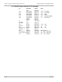
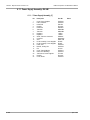
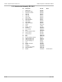
List of Figures
April 1992
Figure
2-1 SW1 on the TRANSPORT CONTROL PCA . . . . . . . . . . . . . . . 2-2
2-2 Controls on the BIAS CONTROL PCA . . . . . . . . . . . . . . . . . . . 2-3
2-3 Assembling the Mounting Flanges . . . . . . . . . . . . . . . . . . . . . . 2-6
2-4 Attaching the Stand Assembly . . . . . . . . . . . . . . . . . . . . . . . . . 2-6
2-5 Assembling Auto Locator and Remote Control Unit . . . . . 2-7
2-6 Desk Top Stand Assembly . . . . . . . . . . . . . . . . . . . . . . . . . . . . . 2-8
2-7 Roll-Around Stand Assembly . . . . . . . . . . . . . . . . . . . . . . . . . . 2-8
2-8 MTR-90III Logic and Power Connections . . . . . . . . . . . . . . . 2-9
2-9 AC Power Cord Wiring . . . . . . . . . . . . . . . . . . . . . . . . . . . . . . . . 2-10
2-10 XLR Cable Wiring for Audio Connections . . . . . . . . . . . . . 2-10
Figure
3-1
3-2
3-3
3-4
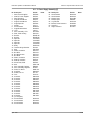
Figure
4-1 Tape Threading Path . . . . . . . . . . . . . . . . . . . . . . . . . . . . . . . . . . . 4-3
Figure
5-1 Head Shield Screw and Guide Rails . . . . . . . . . . . . . . . . . . . .
5-2 Reel Motor Replacement . . . . . . . . . . . . . . . . . . . . . . . . . . . . . .
5-3 Brake Pad Replacement . . . . . . . . . . . . . . . . . . . . . . . . . . . . . . .
5-4 VU Meter Lamp Replacement . . . . . . . . . . . . . . . . . . . . . . . . . .
5-5 Head Shield Position Adjustment . . . . . . . . . . . . . . . . . . . . . .
Figure
6-1 Transport Deck Plate Removal . . . . . . . . . . . . . . . . . . . . . . . . . 6-3
6-2 Record/Reproduce Head Azimuth Adjustment . . . . . . . . . . 6-4
6-3 Swing Arm Travel Limit Adjustment . . . . . . . . . . . . . . . . . . . . 6-6
6-4 Fast Forward and Rewind Solenoid Adjustment . . . . . . . . . 6-7
6-5 Tape Lifter Adjustment . . . . . . . . . . . . . . . . . . . . . . . . . . . . . . . . . 6-9
6-6 Measuring Brake Tension . . . . . . . . . . . . . . . . . . . . . . . . . . . . . 6-10
6-7 Brake Tension Adjustment Nut . . . . . . . . . . . . . . . . . . . . . . . . 6-10
6-8 Reel Turntable Height Adjustment . . . . . . . . . . . . . . . . . . . . . 6-11
6-9 REEL CONTROL PCA Front Panel . . . . . . . . . . . . . . . . . . . . . 6-12
6-10 TRANSPORT CONTROL PCB Assembly . . . . . . . . . . . . . . 6-14
6-11 Capstan Tachometer Adjustment . . . . . . . . . . . . . . . . . . . . . 6-16
6-12 Capstan Control PCB Assembly . . . . . . . . . . . . . . . . . . . . . . 6-18
6-13 Repro Section of Audio PCB Assemblies . . . . . . . . . . . . . 6-20
6-14 Sync section of Audio PCB Assemblies . . . . . . . . . . . . . . 6-21
6-15 Bias Section of Audio PCB Assemblies . . . . . . . . . . . . . . . 6-22
6-16 Record Section of Audio PCB Assemblies . . . . . . . . . . . . 6-23
6-17 Phase Compensation Adjustments . . . . . . . . . . . . . . . . . . . 6-23
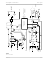
6-18 MTR-90III Block Diagram . . . . . . . . . . . . . . . . . . . . . . . . . . . 6-25
Figure
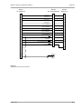
7-1 MTR-90III Dimensions . . . . . . . . . . . . . . . . . . . . . . . . . . . . . . . . . 7-4
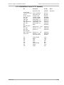
MTR-90III Transport Features and Controls . . . . . . . . . . . . . 3-2
Rear Panel Features . . . . . . . . . . . . . . . . . . . . . . . . . . . . . . . . . . . 3-5
Remote Control Unit Features . . . . . . . . . . . . . . . . . . . . . . . . . . 3-7
Auto Locator Front Panel Features . . . . . . . . . . . . . . . . . . . . 3-10
5-4
5-6
5-7
5-8
5-8
xi
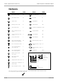
List of Tables
April 1992
Table
2-1 SW1 on the TRANSPORT CONTROL PCA . . . . . . . . . . . . . . . 2-2
2-2 SW2 and SW3 on the TRANSPORT CONTROL PCA . . . . . 2-3
2-3 Reproduce EQ Selection: BIAS CONTROL PCA . . . . . . . . . 2-3
2-4 Cue Level Attenuation Selector: BIAS CONTROL PCA . . . 2-4
2-5 NR Remote Connector Pin Assignments . . . . . . . . . . . . . . 2-11
2-6 Jumper Switch Settings on EXT CONNECTION PCA . . . . 2-11
2-7 EXT. CLOCK Pin Assignments . . . . . . . . . . . . . . . . . . . . . . . . . 2-12
2-8 Baud Rate Settings . . . . . . . . . . . . . . . . . . . . . . . . . . . . . . . . . . . 2-12
2-9 Serial I/O Connector Pin Assignments . . . . . . . . . . . . . . . . . 2-12
2-10 Parallel I/O Connector Pin Assignments . . . . . . . . . . . . . . 2-13
Table
3-1 Table of Monitor Output Modes . . . . . . . . . . . . . . . . . . . . . . . . 3-9
Table
4-1 Modes of Operation . . . . . . . . . . . . . . . . . . . . . . . . . . . . . . . . . . . . 4-2
Table
6-1 Gain Adjustment Trimmer . . . . . . . . . . . . . . . . . . . . . . . . . . . . 6-13
6-2 Bias Chart . . . . . . . . . . . . . . . . . . . . . . . . . . . . . . . . . . . . . . . . . . . . 6-22
xiii
Section 1 Introduction
This section introduces the MTR-90III Tape Recorder and explains the
different parts of this manual.
1.1 The Otari MTR-90III Tape Recorder . . . . . . . . . . . . . . . . . . . . . . . . . . . . . 1-2
1.2 Using This Manual . . . . . . . . . . . . . . . . . . . . . . . . . . . . . . . . . . . . . . . . . . . . . . . . . 1-3
1.2.1 Organization . . . . . . . . . . . . . . . . . . . . . . . . . . . . . . . . . . . . . . . . . . . . . . . . . . . . . 1-3
1.2.2 Conventions Within This Manual . . . . . . . . . . . . . . . . . . . . . . . . . . . . . . . . . . 1-4
October 1990
1-1
Section 1 Introduction
MTR-90III Operation and Maintenance Manual
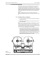
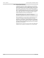
1.1 The Otari MTR-90III Tape Recorder
The Otari MTR-90III records and reproduces 1" or 2" master tapes in an
8-track, 16-track or 24-track format according to the head assembly and the
number of Audio PCB Assemblies. Tension is distributed uniformly across
the tape surface by a pair of wide diameter pinchrollerless spindles, the
capstan and the tachometer. This design eliminates contact between the tape
drive and the oxide, allowing virtually unlimited safe passes of valuable
master tapes. Mechanical integrity and long-term stability are ensured by a
massive, precision top plate and a unitized, welded steel chassis. The newly
designed High Speed Motor Drive Amplifier features self protection and reelend deceleration for better tape manipulation and more efficient editing.
Ultra-high torque DC servo reel motors provide fast winding even with 14"
reels, and ensure rapid start-ups to full stable record/play speed. The entire
machine is modular in construction, including the computerized transport
control logic, for high reliability and serviceability.
The MTR-90III is loaded with convenient features such selection of external
speed reference, vari-speed, or 2 crystal-locked speeds—15/30 ips (38/76
cm/s) or 7.5/15 ips (19/38 cm/s). The reels can be gently rocked back and
forth for editing with the easy-to-use Cue Wheel or by hand turning the
capstan. Push buttons also provide for tension release and retraction of the
motor-driven head shields to expedite editing. A practical splicing block and
a spot erase function for erasure of unwanted tracks are also provided in
front of the head assembly.
The electronics are highly refined. A single PCB Assembly approach has
been used for the RECORD/PLAY AUDIO and BIAS PCB Assemblies for each
channel simplifying setup and service. Active mixing of audio and bias in the
record circuitry, proper utilization of high slew rate IC op-amps, and discrete
components at critical stages ensure the cleanest and quietest recordings.
There are, of course, individual channel calibrations for bias, low and high
speed EQ and gain, and a low and high speed record PHASE COMP trimmer
for improving complex waveform characteristics. In addition, a 3 position
Master BIAS SELECT switch (with 3 corresponding trimmers) enables the
entire machine, once aligned, to be rapidly switched to accommodate the
bias requirements of different tapes. For further convenience, a single test
input jack applies test/alignment signal to all inputs. There is automatic
switching between sync reproduce and input monitor when the machine is
switched between play and stop, fast winding modes, and of course
Rec/Ready to record enable. Dip switches on the TRANSPORT CONTROL
PCB Assembly permit these logic functions to be changed to suit the
preference of the user.
Stable ACTIVE BALANCE Circuitry has been used in the input circuit. In the
output circuit, balanced or unbalanced operation can be selected.
(Transformer output or input may be ordered separately.) In addition, a
SERIAL I/O CONNECTOR, conforming to the RS232 standard for direct
conversation with a computer, and an Otari Standard Parallel I/O Interface are
provided for extended external control.
The model CB-147 Remote Control Unit is included as standard equipment.
It features the same transport control buttons as the MTR-90III and provides
individual function selections for each channel (Repro/Sel·Rep/Input), master
function selections for all channels at once (All Inputs/All Sel·Rep/All Repro),
and a master "All Safe" function. Also located on the Remote Control Unit are
a Speed Reference Selector switch (VARI, FIX, EXT), a Pitch Control knob,
and a Digital Readout indicating speed in percentage or inches per second
(ips).
1-2
October 1990
MTR-90III Operation and Maintenance Manual
Section 1 Introduction
The optional CB-148 Auto Locator with a built-in stop watch attaches to the
same stand as the CB-147 and provides independent readouts and controls
for the elapsed tape time and locate time. The locator also features zero cue,
10 keyboard assignable memories (keyboard or direct tape time memories)
with direct recall, a shuttle function for repeating any desired segment of the
tape, and other time saving functions.
The optional EC-101 Plug-in Chase Synchronizer allows the MTR-90III to be
controlled via SMPTE/EBU time code for slave operation. With the optional
CB-121 Synchronizer Remote Control Unit, the EC-101 can input TC offset as
well as monitor master TC, slave TC and difference of time codes.
CAUTION: The DC reel motors develop substantial torque. Never place a
hand, clothing or other objects inside, on top or near a reel or swing arm
when initiating tape motion. When using the Remote Session Controller or
Auto Locator, always make sure anyone near the transport is aware of the
potential hazard posed by the high torque motors which are capable of
increasing the tape tension very rapidly.
1.2 Using This Manual
1.2.1 Organization
This manual is divided into nine sections beginning with this Introduction
which contains general information about the machine and about the manual.
Section 2 Installation and Inspection: This section of the manual contains
the information required when unpacking and installing the MTR-90III for the
first time or when interfacing the machine to a mixing console or other
equipment.
Section 3 Controls and Indicators: This section of the manual contains a
keyed guide to the controls and indicators and provides detailed information
about each control and its functions. This section of the manual should be
used whenever a question about the function of a particular control or
indicator arises.
Section 4 Operation: This section of the manual describes the operation of
the MTR-90III. It contains a list of all the operating modes of the machine
and an in-depth description of all MTR-90III operations organized by
function. The functional checkouts in Section 2 should be carefully
performed when the MTR-90III is first installed.
Section 5 Maintenance: This section covers the routine maintenance
procedures necessary to keep the MTR-90III in peak operating condition.
Section 6 Alignment: This section of the manual covers the information
needed to perform the routine alignments and calibrations associated with
normal operation of the MTR-90III. You should refer to this section of the
manual when performing the normal maintenance and calibration routines
that must be done to keep the recorder operating at peak performance.
Section 7 Specifications: This section of the manual contains the operating
specifications for MTR-90III series machines.
SECTION 8 Printed Circuit Board Layouts: This section of the manual
contains two-color "x-ray" views of major printed circuit boards showing
component locations and foil traces.
October 1990
1-3
Section 1 Introduction
MTR-90III Operation and Maintenance Manual
SECTION 9 Exploded Views and Parts Lists: This section of the manual
contains assembly drawings of the machine "exploded" to show internal parts
and hardware, and the order of assembly. Each exploded view is keyed to an
accompanying parts list showing Otari part numbers and descriptions for all
mechanical components.
1.2.2 Conventions Within This Manual
PCB Assemblies: The term PCB Assembly is used in this manual to refer to
a printed circuit board which has components (resistors, connectors, etc.)
mounted on it. The term PCB or Printed Circuit Board when used alone
refers to the "bare" printed circuit board without components. The term PCB
is rarely used outside of the electrical and mechanical parts lists. When a
PCB Assembly is referred to in the text, the name or function of that PCB
Assembly will usually be given in ALL CAPITAL letters.
ALL UPPER CASE: Generally, this manual uses all upper case type to
describe a switch or control when that item is similarly labeled on the
machine (e.g., the PLAY button).
First Letter: Where a switch or button is not Upper Case labeled or the
reference is unclear, only the first letter of the item is capitalized (e.g., the
Cue Wheel near the CUE button). Machine status or operating modes are
described with an upper case first letter (e.g., you press the PLAY button to
place the machine in Play mode).
( ), [ ] - Normal parentheses ( ) are used for examples and parenthetic
comments. Square brackets [ ] are used to refer to certain illustrations.
When used in text, the square brackets are either references to the same
figure as noted in that sub-section (e.g., [3], meaning the part labeled "3" in
the figure noted) or are preceded by the figure number (e.g., Fig. 2-1, [3],
meaning "3" in Figure 2-1).
Although this manual is intended for 1" 8CH, 2" 16CH and 2" 24CH
operations, the following description deals only with 2" 24CH operation.
Please note that all explanations apply to 1" 8CH and 2" 16CH as well, even if
remarks to that effect cannot be found.
We encourage you to read this manual carefully now, and to again review it
after you have had a while to become familiar with the MTR-90III. The more
you know about your machine, the more you can benefit from its many
versatile features.
1-4
October 1990
Section 2 Installation
Most MTR-90III units are unpacked and tested by local Otari dealers making
the following unpacking and checkout procedures unnecessary.
The MTR-90III Recorder, CB-147 Remote Control Unit, logic and power
cables, brackets and other related items are shipped partially assembled.
Open the crates carefully and save packing materials at least until proper
operation has been verified. Connect the power and test the system only after
unpacking all components and assembling them according to the
instructions.
The MTR-90III weighs approximately 200 kg (400 pounds). At least two
strong people should work together during unpacking and the initial setup to
avoid physical strain and to ensure gentle handling of the equipment.
IMPORTANT NOTE: If serious problems are apparently caused by shipping
damage, whether concealed or obvious, a claim must be filed with the
delivering airline, freightline or other carrier, and Otari or the nearest Otari
representative must be notified. Retain all packing materials for evidence in
damage claims. Failure to do so may weaken any claims! To replace any parts
under warranty, obtain a return authorization form from Otari or its
representative. Do not attempt to apply power or operate the machine until
proper repairs have been completed.
2.1 Inspection . . . . . . . . . . . . . . . . . . . . . . . . . . . . . . . . . . . . . . . . . . . . . . . . . . . . . . . . . . . 2-2
2.2 Assembly of Remote Control Unit . . . . . . . . . . . . . . . . . . . . . . . . . . . . . . . 2-6
2.3 Stand Assembly (Remote Control Unit/Auto Locator) . . . . . . . . 2-7
2.4 Connections . . . . . . . . . . . . . . . . . . . . . . . . . . . . . . . . . . . . . . . . . . . . . . . . . . . . . . . . 2-9
2.4.1
2.4.2
2.4.3
2.4.4
2.4.5
Cable Connections . . . . . . . . . . . . . . . . . . . . . . . . . . . . . . . . . . . . . . . . . . . . . . . 2-9
NR Remote Connector . . . . . . . . . . . . . . . . . . . . . . . . . . . . . . . . . . . . . . . . . . 2-11
EXT CLOCK Connector . . . . . . . . . . . . . . . . . . . . . . . . . . . . . . . . . . . . . . . . . . 2-11
Serial I/O Connector . . . . . . . . . . . . . . . . . . . . . . . . . . . . . . . . . . . . . . . . . . . . 2-12
Parallel I/O Connector . . . . . . . . . . . . . . . . . . . . . . . . . . . . . . . . . . . . . . . . . . . 2-13
2.5 Power Supply Conversion . . . . . . . . . . . . . . . . . . . . . . . . . . . . . . . . . . . . . . . 2-14
October 1990
2-1
Section 2 Installation
MTR-90III Operation and Maintenance Manual
2.1 Inspection
Before making any electrical connections, the equipment should be inspected
visually. If there is any evidence of damage due to rough handling in
shipping, it is the responsibility of the customer to notify the carrier and
submit a claim. Do not connect or attempt to use the MTR-90III or
accessories until this inspection has been made.
1. Inspect the equipment for any parts which may have become loose or
damaged during shipping.
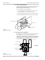
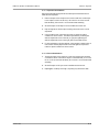
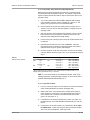
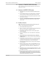
2. Check the plug-in PCB Assemblies in the card cages:
A. Grasp the top of each door in the front of the MTR-90III and pull to
open.
CAUTION! The edges of the doors are very sharp.
B. The upper card cage should contain the proper quantity of Audio
boards (i.e., 8, 16 or 24). Eight and sixteen track versions of the
MTR-90III will have no cards in slots 9–24 or 17–24 respectively.
C. The lower card cage should contain the POWER SUPPLY PCB
Assembly and PCB Assemblies numbered 1–7 installed in the
correspondingly numbered card slots.
#1
#2
#3
#4
REEL CONTROL PCB Assembly
CAPSTAN CONTROL PCB Assembly
TRANSPORT CONTROL PCB Assembly
MASTER CPU PCB Assembly
#5 I/O CONTROL PCB Assembly
#6 TAPE COUNTER PCB Assembly
#7 BIAS PCB Assembly
R126
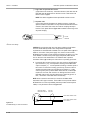
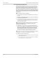
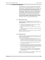
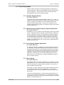
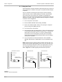
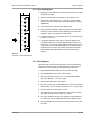
D. Remove the TRANSPORT CONTROL PCB Assembly (#3) and
examine DIP switch SW1 (Figure 2-1).
O 1
N
2
3
4 O
N
SW1
C90
Figure 2-1
SW1 on the TRANSPORT CONTROL PCA
SW1-2 and SW1-3 have been set to the ON position at the factory.
These switches are for selecting Stand-by mode. Stand-by mode
automatically switches the Output Monitor to Input mode when the
following conditions are met: the tape is in Stop or Fast Wind mode,
the READY/SAFE switches have been set to the READY position and
either the ALL REPRO or ALL SEL·REP button on the Remote
Control Unit has been pressed. This mode is called "Stop Stand-by"
when entered from the Stop mode and "Fast Stand-by" when entered
from Fast Wind modes. SW1-1 and SW1-4 have been set to the OFF
position at the factory. When the Master Audio Attenuation Switch
(SW4 on the BIAS CONTROL PCB Assembly) is off, audio output is
attenuated when the machine is in fast wind modes (see Figure 2-2
and Table 2-4). When SW1-1 on the TRANSPORT CONTROL PCB is
off, the Audio output will be attenuated when the CUE button (Lifter
Defeat) is pressed during Fast Wind modes. When SW1-1 is on, no
audio attenuation will take place when the lifters are defeated.
2-2
October 1990
MTR-90III Operation and Maintenance Manual
Section 2 Installation
Table 2-1
SW1 on the TRANSPORT CONTROL PCA
SWITCH
FUNCTION
EFFECT
SW1-1
Hand Cueing Capstan
SW1-2
SW1-3
SW1-4
Stop Stand-by
Fast Wind Stand-by
Play Start Inhibit
ON: Defeats Stop Stand-by input switching, allowing audio to be
monitored while hand cueing in Stop mode.
OFF: Audio output stays in Input mode while in Stop if SW1-2 is on.
ON: Switches to Input monitor in Stop mode.
ON: Switches to Input monitor in Fast Wind mode.
OFF: Mutes audio output until transport stabilizes at PLAY speed.
SW2 and SW3, which select the head shield functions, are also
mounted on the TRANSPORT CONTROL PCB Assembly. The
functions of these switches are as follows.
Table 2-2
SW2 and SW3 on the TRANSPORT CONTROL PCA
SW2
SW3
0 (OFF)
1 (ON)
Shield does not move in Fast Wind mode.
Independent button control over shields in Unload mode.
Shield retracts in Fast Wind mode
Shield retracts in Unload mode.
SW2 and SW3 have been set to 0 and 1 respectively when shipped
from the factory.
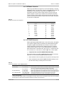
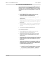
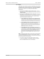
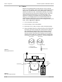
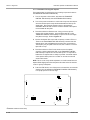
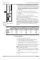
E. Remove the BIAS CONTROL PCB Assembly (Card #7) and examine
DIP switches SW3, SW5 and SW6 (Figure 2-2). These switches
select the Reproduce and Record EQ for 15 ips (NAB/IEC) and 30
ips (AES/IEC). The switches should be set in accordance with the
specifications of the tape in use. See Figure 2-2 and Table 2-3.
RV5
IC 18
SW3
1
C47
C44
0
SW4 SW5 SW6
1
1
1 ON
OFF
0
0
0
IC3
IC 17
IC1
Figure 2-2
Controls on the BIAS CONTROL PCB Assembly
Table 2-3
Reproduce EQ Selection: BIAS CONTROL PCB Assembly
SW3
SW5
SW6
TAPE SPEED
EQ CURVE
TIME CONSTANT
—
—
OFF
ON
—
—
OFF
ON
ON
OFF
—
—
30 ips
30 ips
15 ips
15 ips
AES
IEC
NAB
IEC
17.4 µs + infinity
35.0 µs + infinity
50.0 µs + 3180 µs
35.0 µs + infinity
SW4 is the Master Audio Attenuation Switch and affects the
operation of SW1-1 on the TRANSPORT CONTROL PCB Assembly.
October 1990
2-3
Section 2 Installation
MTR-90III Operation and Maintenance Manual
Table 2-4
Cue Level Attenuation Selector: BIAS CONTROL PCA
SWITCH POSITION
TAPE SPEED
AUDIO EFFECT AT WIND SPEEDS
SW4 ON
SW4 OFF
15/30 ips
15/30 ips
Not Changed
Attenuated
F.
All cards should be firmly seated in their mating connectors and in
the correct locations.
G. Close the doors to the card cages.
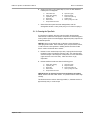
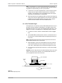
3. From the front of the machine, check the connectors and components
beneath the MTR-90III transport.
A. Remove the 3 allen head cap screws along the slot in the front of
the unit just above the VU meter panel. The meter panel is hinged
along its lower edge and is held closed by friction from rubber
gaskets.
B. Grasp the rail just below the screw holes and gently pull while
pivoting the meter panel open until the safety latches hold it in a
horizontal position. Do not to drop the panel when pulling it.
C. Check the following connectors to be sure they are firmly mated.
❑
The connector on the bracket for each Take-Up reel motor
assembly.
❑
The 3 connectors located on the head shield retraction
mechanism (beneath the head assembly).
❑
The connector on the black sensor beneath each swing arm
assembly.
❑
The connector on the tachometer (beneath the tachometer
roller on the Supply side of the transport).
❑
The 3 connectors near the tape lifter solenoid (below the head
assembly on the Supply reel side).
❑
The connectors on the CAPSTAN MOTOR PCB Assembly and
the connector which is located below the head assembly near
the capstan motor.
❑
The 3 connectors on the VU METER PCB Assembly and all the
small connectors for the READY-REC LED PCB Assemblies
mounted with the VU meters.
D. Check for any obviously loose or damaged components and any cut
or broken wires. Then close the meter panel and reinstall the 3
screws removed in Step 3A.
4. From the rear of the machine, check the connectors and components
behind the upper card cage.
A. Remove the 6 phillips head screws, dress washers, and nylon
washers that secure the edges of the middle panel on the back of
the machine (the one with the XLR connectors). The panel is hinged
along its lower edge and by gently pulling the top, it will pivot open
until its safety latches hold it in a horizontal position.
B. Remove the 4 phillips head screws, dress washers and nylon
washers that secure the edges of the top panel on the back of the
machine (the one with the fan). This panel is also hinged along its
lower edge.
2-4
October 1990
MTR-90III Operation and Maintenance Manual
Section 2 Installation
C. Check the following connectors to be sure they are firmly mated.
❑
The many connectors located on the back of the upper card
cage mother board.
❑
On the top panel there are three motor drive transistor
assemblies. Each assembly has two large connectors and three
small connectors. Check these connectors.
D. The SMPTE-CUE slide switch on the left side of the upper card cage
mother board should be set to the "OFF" position. This switch is only
used when externally linking the MTR-90III to a suitable SMPTE
(Society of Motion Picture and Television Engineers) time code
synchronizer. Refer to §4.2.11.
E. Check for any obviously loose or damaged components and any cut
or broken wires. Then close the middle and top panels and reinstall
the phillips screws, dress washers and nylon washers removed in
Step 4A.
CAUTION: When closing this back panel, use care to ensure that no wires are
pinched between the panel and MTR-90III chassis.
5. From the rear of the machine, check the connectors and components
behind the lower card cage.
A. Remove the 4 phillips head screws, dress washers and nylon
washers that secure the edges of the bottom panel on the back of
the machine (the one with the AC power and logic connectors). Lift
the bottom of the panel away from the machine, slide it down an
inch so its upper flange clears the hinge screws of the panel above,
then set the bottom panel aside. (The electrical connectors are
mounted to sub-plates that remain attached to the MTR-90III
chassis.)
CAUTION: Be sure the AC power cable is not connected to the MTR-90III
at this time.
B. Check the following connectors and components to be sure they are
firmly seated.
❑
The many connectors located on the back of the lower card
cage mother board.
❑
The 2 relays on the back of the lower card cage mother board
(they should be plugged in and secured with metal retaining
clips).
C. Check for any obviously loose or damaged components and any cut
or broken wires. Then replace the panel, inserting the upper flange
first so it clears the hinge screws of the panel above, and secure it
with the 4 screws, dress washers and nylon washers removed in
Step 5A.
D. Remove the 5 phillips head screws, dress washers and nylon
washes that secure the cover panel on the left side of the chassis.
check the several connectors mounted on the DS-1Z Power Supply
Assembly for proper engagement.
6. If minor faults or discrepancies are noted during the foregoing
inspection procedures, make the necessary corrections and/or
adjustments and proceed with the installation.
October 1990
2-5
Section 2 Installation
MTR-90III Operation and Maintenance Manual
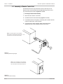
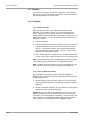
2.2 Assembly of Remote Control Unit
The Remote Control Unit is provided with a stand for desk top use. The
Remote Control Unit can be fitted with the angle adjusting knob for use at
any convenient position. Refer to Figures 2-3 and 2-4.
❑
Attaching the ZA-52J Stand Assembly
1. Remove the two sections of the stand.
2. Assemble the ZA-52J Stand Assembly (Figures 2-3 and 2-4).
3. Put the Remote Control Unit gently on the fitting arm and attach the Unit
to the arm with the four screws provided.
4. Loosen the knob to adjust the angle. When at the desired angle,
retighten the knob to hold the Remote Control Unit secure.
NOTE: THE THICK EDGE OF THE CARRIER
BLOCK FACES THE REMOTE CONTROL BOX,. THE
FLAT EDGE OF THE BLOCK FACES DOWN.
Figure 2-3
Assembling the Mounting Flanges
NOTE: THE THICK EDGE OF THE CARRIER
BLOCK FACES THE REMOTE CONTROL BOX,.
THE FLAT EDGE OF THE BLOCK FACES UP.
Figure 2-4
Attaching the Stand Assembly
2-6
October 1990
MTR-90III Operation and Maintenance Manual
Section 2 Installation
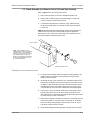
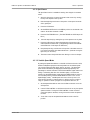
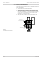
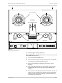
2.3 Stand Assembly (for Remote Control Unit and Auto Locator)
Refer to Figure 2-5 for the following instructions.
1. Remove the four pieces on the side of the Remote Control Unit.
2. Place the CB-147 Remote Control Unit panel upright on a flat work
surface. Connectors should be facing away.
3. Locate the two large aluminum V-brackets. Using 3 allen head cap
screws per bracket, attach one V-bracket to each side of the Remote
Control Unit.
NOTE: While the brackets are nearly identical, each has the matte finish on
different sides. The shiny side of each bracket should rest against the
Remote Control Unit, and the leg of the bracket with 2 large holes (not 3)
should be attached to the Remote Control Unit.
AUTO LOCATOR
NOTE: THE THIN EDGE OF THE
CARRIER BLOCK FACES THE REMOTE
CONTROL UNIT. THE FLAT SIDE OF
THE BLOCK FACES THE JUNCTION OF
THE FRONT PANELS OF THE TWO
BOXES. THE SAME BLOCK POSITION
IS USED FOR BOTH DESK TOP AND
ROLL AROUND STANDS.
REMOTE CONTROL UNIT
Figure 2-5
Assembling Auto Locator and Remote Control Unit
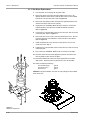
4. Locate the 4 brass flanges. Attach the 2 larger mounting flanges to the
middle of the two V-brackets (on the matte side) using 3 flat head
phillips screws per flange.
5. Set the CB-148 Auto Locator directly on top of the Remote Control Unit
between the V-brackets to which it will be secured. Lift the Auto Locator
up slightly so that the middle screw hole in the remaining leg of each Vbracket aligns with the corresponding hole in the Auto Locator. Insert
one allen head cap screw into each of these holes and partially tighten.
6. Pivot the Auto Locator so that the remaining two screw holes in each
bracket align with the holes in the Auto Locator and insert two more
allen head cap screws per bracket. Then tighten all the allen head screws
to secure the Auto Locator to the bracket.
7. Examine the 2 identical square black carrier blocks. Notice that one side
of the part is labeled “A” near the center, and the other “B.” Press the
blocks onto the mounting flanges of the V-brackets so the “A” side of
each block is adjacent to the V-bracket.
8. Insert the remaining brass bearing flanges in each of the carrier blocks.
October 1990
2-7
Section 2 Installation
MTR-90III Operation and Maintenance Manual
9. Insert the threaded screw of each knurled knob through the bearing
flange and carrier block and screw it into the mounting flange, but do
not tighten.
10. Notice that the carrier blocks are flat on one edge. The carrier blocks
should be rotated so that the flat edge faces forward, mid-way between
the front panels of the Remote Control Unit and Auto Locator. Refer to
Figure 2-6 or 2-7. Tighten the knurled knobs.
NOTE: In both illustrations, the carrier block orientation is the same. The flat
side is up, and the thinner flange faces the V-bracket.
11. Attach the carrier block to either the mounting rails for desk-top use
(Figure 2-6) or the optional roll-around stand (Figure 2-7).
A. Use 4 flat-head phillips screws to attach each of the two rails to the
block as shown in Figure 2-6.
B. First fasten the U-bracket to the upright member of the roll-around
stand using 3 oval head phillips screws. Then use 2 cap-head allen
screws to attach each carrier block to the U-bracket as shown in
Figure 2-6. The combined Remote Control Unit/Auto Locator/Ubracket/upright assembly can now be inserted in the roll-around
base.
12. The Remote Control Unit/Auto Locator assembly can be tilted to any
working angle by loosening the knurled knobs, and the locking in place
by tightening the knobs.
Figure 2-6
Desk Top Stand Assembly
2-8
Figure 2-7
Roll-Around Stand Assembly
October 1990
MTR-90III Operation and Maintenance Manual
Section 2 Installation
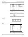
2.4 Connections
Before connecting cables to the MTR-90III, it is recommend that the 2 rubber
bumpers supplied be screwed into two of the 4 corners of the chassis on the
rear of the machine (the corners chosen depend on the specific installation).
The bumpers help guard cable connectors from inadvertent damage.
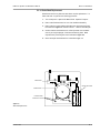
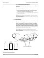
2.4.1 Cable Connections
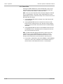
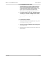
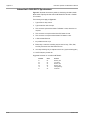
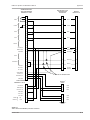
1. Locate and install the following cables supplied with the MTR-90III
(there will be 4 cables if the Auto Locator is installed, 3 if not) as shown
in Figure 2-8. All chassis connectors are clearly labeled with the
corresponding functions. BE SURE ALL CONNECTORS ARE POSITIVELY
MATED otherwise the tape machine may behave erratically.
BUZZER
NR REMOTE
TO DECK
AMP REMOTE
13-24 CH
AMP REMOTE
1-12 CH
TO DECK
REMOTE
TO AMP
13-24 CH
AUTO LOCATOR
POWER
TO AMP
1-12 CH
Figure 2-8
MTR-90III Logic and Power Connections
❑
Remote cable for transport logic:
(37-pin Cannon D connectors). The female end of the cable plugs into
the rear of the MTR-90III, and the male end into the Remote Control
Unit. They should then be secured with the two screws supplied.
❑
Two remote cables for mode switching (CH 1–12 and CH 13–24):
(50-position AMP connectors). These two cables are identical and have
male connectors on both ends. Carry out correct connections taking care
not to make mistakes. A clip-lock is attached to the female side (Panel
side). Spread the clip fully open, insert the cable, then snap the lock
forward to lock the cable in place.
CAUTION: Be sure to follow each cable through from MTR-90III to Remote
Control Unit. If a single cable is inadvertently looped between adjacent
connectors on the MTR-90III or Remote Control Unit, circuit damage could
result. Such damage is not covered by the Otari Warranty.
October 1990
2-9
Section 2 Installation
MTR-90III Operation and Maintenance Manual
❑
Logic cable for optional auto locator:
(50-pin Cannon D connectors). Insert the male end of this cable into the
MTR-90III and the female end into the Auto Locator. Then secure with
the two screws supplied.
NOTE: This cable is supplied with the optional CB-148 Auto Locator.
❑
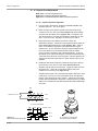
AC power cord:
(3-pin mains plug plus threaded 3-pin female connector). Orient the
special connector on the cable so its key matches the MTR-90III chassis
connector, and insert. Then screw the connector coupling securely to
lock the cord in place. Refer to Figure 2-9 for details on the wiring of the
AC power line plug.
1
}
WHITE
ACTIVE
BLACK
GREEN — GROUND
3
2
Figure 2-9
AC Power Cord Wiring
CAUTION: Do not plug the other end of the power cable into the AC mains
until it is verified that the actual mains voltage meets the specified
requirements for the MTR-90III as labeled on its rear panel. Refer to §2.6 for
details on conversion of the power supply. Also, check to make sure the
MTR-90III power switch is turned off before plugging in the power cord. This
circuit breaker is located on the power supply front panel, behind the left
door on the front of the machine and is off when the lever is pressed
downward. Refer to §4.2.1 Step 3 for instructions on powering up the unit.
2. Connect the buss output connectors from the console to the MTR-90III
input connectors (10 kΩ load impedance, floating) and the MTR-90III
output connectors ( 5 Ω source impedance, floating) to the line inputs of
the console. To avoid hum-inducing ground loops, be sure to follow a
sensible grounding scheme such as telescoping shields, e.g., single
common ground point (connect shields at the console, not at the tape
machine or vice versa, then connect a 12 AWG ground wire from the
MTR-90III frame to the console mother board or patch bay ground. A
600 Ω termination of the MTR-90III is unnecessary.
NOTE: Audio connections are made via 2-conductor shielded cables
terminated in XLR-type connectors. These cables are not provided with the
MTR-90III but are commonly available (standard professional microphone
cables) or may be wired as shown in Figure 2-10.
MTR-90III INPUT
MTR-90III OUTPUT
XLR-3-31
XLR-3-32
PIN 2 AUDIO SIGNAL LOW
PIN 3 AUDIO SIGNAL HIGH
PIN 1 SHIELD
Figure 2-10
XLR Cable Wiring for Audio Connections
2 - 10
October 1990
MTR-90III Operation and Maintenance Manual
Section 2 Installation
2.4.2 NR Remote Connector
When using Noise Reduction equipment, it can be automatically or remotely
switched by means of a 50-pin Amp. connector on the MTR-90III (mates with
AMPHENOL 57 series 50p plug or equivalent). See Table 2-5 for pin
assignment of this logic connector. Relay contacts only are provided. No
positive, negative or ground logic conditions are connected to these relay
contacts. One pair of relay contacts per channel is provided, and they close
(make contact) when the channel is in Input mode. The contacts are rated at
24 volts DC, 50 milliamperes.
Table 2-5
NR Remote Connector Pin Assignments
CHANNEL
PIN NUMBERS
1
2
3
4
5
6
7
8
9
10
11
12
1 & 26
2 & 27
3 & 28
4 & 29
5 & 30
6 & 31
7 & 32
8 & 33
9 & 34
10 & 35
11 & 36
12 & 37
CHANNEL
PIN NUMBERS
13
14
15
16
17
18
19
20
21
22
23
24
NC
13 & 38
14 & 39
15 & 40
16 & 41
17 & 42
18 & 43
19 & 44
20 & 45
21 & 46
22 & 47
23 & 48
24 & 49
25 & 50
2.4.3 EXT CLOCK Connector
When the MTR-90III SPEED MODE switch is set to EXT position, the capstan
motor speed is capable of being controlled by an external reference signal.
The signal is applied via the External Clock connector on the rear of the
machine. Specifically, the external clock reference frequency is 9,600 Hz
(nominal value for the set 15 ips or 30 ips speed selected). The reference
signal should be at TTL level with a 50% duty cycle (i.e., a square wave that
is 0 volts when off, +5 volts when on). Refer to §4.2.11 for further details.
❑
Jumper Switches on the EXT CONNECTION PCB Assembly
The Jumper Switches on the EXT CONNECTION PCB Assembly must be set
before use. To access the EXT CONNECTION PCB Assembly:
1.
Remove the rear connector panel by removing the four securing screws.
2.
Remove the bracket with the EXT CONNECTION PCB Assembly (on the
left side of the case) by loosening the four M4 screws.
Table 2-6
Jumper Switch Settings on EXT CONNECTION PCA
Jumper
J1 (5V Current)
J2 (Tape Speed Tally)
J3–J5 (Fast Speed Ref)
Position Description
1-2 (=150 mA) *
2-3 (>150 mA)
1-2 (30/15 ips) *
2-3 (15/7.5 ips)
J3-J4 (EXT CLOCK)
J4-J5 (Parallel I/O) *
The 5V supply current from Pin 20 of the EXT CLOCK connector is output at
150 mA for use with the Otari Standard Parallel I/O Connector.
For use with Custom Controllers requiring a signal greater than 150 mA.
Selects tape speed tallies on the Parallel I/O Connector (high speed version)
Selects tape speed tallies on the Parallel I/O Connector (low speed version)
The EXT CLOCK becomes the source for the capstan control clock. 1
The Parallel I/O becomes the source for the capstan control clock. 1
* Factory default settings
1
Use either the EXT CLOCK connector or the Parallel I/O connector as the source for the capstan control clock. Do not attempt
to enter signals from both the EXT CLOCK and Parallel I/O connectors at the same time.
October 1990
2 - 11
Section 2 Installation
MTR-90III Operation and Maintenance Manual
Table 2-7
EXT. CLOCK Pin Assignments
Pin No.
Function
Pin No.
Function
1.
2.
3.
4.
5.
6.
7.
8.
9.
10.
11.
12.
13.
REC TALLY
PLAY TALLY
STOP TALLY
FF TALLY
RWD TALLY
LIFTER DEFEAT
SMPTE CUE
SPD REF. VOLT.
SPD COM.
REC SWITCH
PLAY SWITCH
STOP SWITCH
FF SWITCH
14.
15.
16.
17.
18.
19.
20.
21.
22.
23.
24.
25.
RWD SWITCH
TACHO OUT
9.6K REF.
GND
EXT CLOCK (9.6 kHz nominal)
CAPSTAN TACHO OUT
+5V (150 mA)
FWD/REV (Tape Direction)
N.C.
N.C.
N.C.
N.C.
2.4.4 Serial I/O Connector
The MTR-90 is provided with an interface function which enables direct
conversation with a computer. This function (SERIAL I/O) has the following
three capabilities.
(1) RS-232C
(2) CURRENT LOOP
(3) TTL LEVEL
The baud rate can be selected by the Dip Switches located on the I/O Control
PCB Assembly as given in Table 2-7.
Table 2-8
Baud Rate Settings
BAUD RATE
SWI-1
SWI-2
SWI-3
SWI-4
110 baud
1200 baud
2400 baud
4800 baud
ON
OFF
OFF
OFF
OFF
ON
OFF
OFF
OFF
OFF
ON
OFF
OFF
OFF
OFF
ON
* Factory set to 4800 baud (SW1-4 ON) at the factory.
The SERIAL I/O connector should be connected according to Table 2-8.
Table 2-9
Serial I/O Connector Pin Assignments
Pin No.
Function
Pin No.
Function
1.
2.
3.
4.
5.
6.
7.
8.
9.
10.
11.
12.
13.
Frame GND
Transmit Data
Receive Data
RTS
CTS
DSR
(sig) GND
GND
RDR STA
TXD
RXD
DATA BUSY
DCD
14.
15.
16.
17.
18.
19.
20.
21.
22.
23.
24.
25.
GND
RD CNT
RD COM
TTY OUT
TTY IN
TTY COM
DTR
N.C.
N.C.
N.C.
N.C.
N.C.
For technical information about ASCII Command Characters List, contact
Otari or the local Otari dealer. The necessary connector is DC-25P (TRW
CINCH) or its equivalent.
2 - 12
October 1990
MTR-90III Operation and Maintenance Manual
Section 2 Installation
2.4.5 Parallel I/O Connector
The Otari Standard Parallel I/O Connector is used for connection with
external controlling devices.
Table 2-10
Parallel I/O Connector Pin Assignments
No
Function
1.
2.
3.
4.
5.
6.
9.
10.
11.
12.
13.
14.
16.
17.
18.
19.
20.
21.
22.
28.
29.
30.
32.
33.
34.
35.
36.
37.
RECORD Switch
Low
PLAY Switch
Low
STOP Switch
Low
Fast Forward Switch
Low
Rewind Switch
Low
Lifter Defeat
Low
Shut Off Switch
Low
Record Tally
Low
Play Tally
Low
Stop Tally
Low
Fast Forward Tally
Low
Rewind Tally
Low
Signal Ground
Tach Pulse 1
Tape Direction (Forward=Low)
H/L
Capstan clock (9.6 kHz fixed)
Capstan Control (9.6 kHz nominal)
Low
Tape Speed A 2
Tape Speed B 2
Low
Fast Wind Speed Control Voltage
0-15V
Fast Wind Speed Control Command Low
TC Track Repro Enable
Low
Record Rehearsal Command
Low
+5 V Regulated (max. 150 mA)
±10%
Aux Power
(unreg 24 ~ 40 V max. 500 mA)
Aux Power
Power Ground
Power Ground
1
2
October 1990
Level
In/Out
In
In
In
In
In
In
Out
Out
Out
Out
Out
Out
Out
Out
Out
In
Out
Out
In
In
In
}
Speed
Rate
7.5 ips
15 ips
30 ips
20 pulse/sec
40 pulse/sec
80 pulse/sec
Speed
Speed A
Speed B
7.5 ips
15 ips
30 ips
Low
High
High
High
Low
High
2 - 13
Section 2 Installation
MTR-90III Operation and Maintenance Manual
2.5 Power Supply Conversion
❑
Voltage Conversion
When the machine is used at a different voltage, the connection plug for the
power supply needs to be rewired. To change the wiring, remove the bottom
section of the back panel to expose the voltage selector plug (white nylon
connector) to the “L” bracket on top of the right chassis frame. Change the
wiring of the connector in accordance with the power supply circuit diagram,
or insert a new connector for new voltage.
❑
Frequency Conversion
When the machine is used at a different AC line frequency, the voltage
supplied to the cooling fan must be changed because the efficiency of the
cooling fan is determined by frequency. To change the voltage to the fan,
remove the left side panel of the machine. The conversion switch is found on
the side of the power supply box located at the top right. Set the switch to the
line frequency to be used.
2 - 14
October 1990
Section 3 Controls and Indicators
This section describes the controls, indicators and connectors on the
MTR-90III Tape Recorders, the CB-147 Remote Control Unit and on the
optional CB-148 Auto Locator.
3.1 Transport Controls and Indicators . . . . . . . . . . . . . . . . . . . . . . . . . . . . . . . 3-2
3.2 Rear Panel . . . . . . . . . . . . . . . . . . . . . . . . . . . . . . . . . . . . . . . . . . . . . . . . . . . . . . . . . . 3-5
3.3 Remote Control Unit (CB-147) . . . . . . . . . . . . . . . . . . . . . . . . . . . . . . . . . . . 3-7
3.4 Auto Locator (CB-148) . . . . . . . . . . . . . . . . . . . . . . . . . . . . . . . . . . . . . . . . . . . 3-10
October 1990
3-1
Section 3 Controls and Indicators
MTR-90III Operation and Maintenance Manual
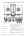
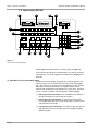
3.1 Transport Controls and Indicators
2
1
TAPE SPEED
3
RESET
HI
LOW
UNLOAD
SPOT ERASE
4
5
CUE
6
7
Figure 3-1
MTR-90III Transport Features and Controls
SHIELD
8
9
11
10
13
12
14
NOTE: Numbers in brackets [ ] refer to Figure 3-1.
The transport buttons glow dimly while power is on. When power is first
turned on, the UNLOAD button [4] is brighter than the other buttons.
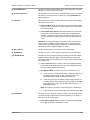
[1] Tape Time Display
The Tape Time Display shows the current tape time.
❑
Resetting the Tape Time Display: Press the RESET button [3] to reset
the Tape Time Display.
[2] TAPE SPEED Button/Indicators
This button selects the desired tape speed. The current speed is indicated by
the adjacent TAPE SPEED indicators. HI speed is 30 ips (76 cm/s) and LOW
speed is 15 ips (38 cm/s) (on some models 15 ips/7.5 ips).
[3] RESET Button
Pressing this button will reset the Tape Time Counter Display [1] to zero. This
button does not reset the Tape Time Readout (§3.4, [1]) on the optional Auto
Locator.
[4] UNLOAD Button
When this button is pressed while the transport is in Stop mode, the reel
servos shut off and the head shields retract so the reels can be turned
manually.
3-2
October 1990
MTR-90III Operation and Maintenance Manual
Section 3 Controls and Indicators
[5] SPOT ERASE Button
This button is used to erase unwanted tracks. Refer to §4.2.9 for a detailed
description on using the Spot Erase mode.
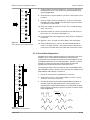
[6] Cue Wheel/Indicators
The Cue Wheel controls the direction and speed of tape motion in Cue mode.
The indicators show the direction of tape motion. (See [7] CUE Button for
further explanation.)
[7] CUE Button
The button is used to enter Cue Mode. When pressed, it illuminates brightly.
There are two main modes.
❑
Normal Cue Mode: When the CUE button is pressed while the transport
is in Stop mode, the direction and speed of tape motion are determined
by the Cue Wheel [6].
❑
Fast Cue Mode (Lifter Defeat): When the CUE button is pressed while
the transport is in Fast Forward or Rewind mode, the tape lifters are
retracted so the tape can be monitored. The lifters remain retracted for
as long as the button is pressed; releasing the button clears Fast Cue
mode.
CAUTION: Be sure the monitor amps are turned off or the volume is down,
otherwise the loudspeakers could be damaged. The volume level of the
monitor speaker can be attenuated by setting SW4 on the BIAS CONTROL
PCB Assembly. Refer to Table 2-4 in §2.1 for details.
[8] Splicing Block
This built-in splicing block is convenient for use during editing.
[9] SHIELD Button
This button is used to control the raising and lowering of the Head Shield.
[10] RECORD Button
This button is used to enter the Transport into Record mode when pressed
together with the PLAY button [11] or while the machine is in Play mode.
Individual channels will not actually record, however, unless they have been
set to Ready mode.
❑
When the RECORD button is pressed, it becomes brightly illuminated,
and the blinking Ready/Safe indicators will remain steadily illuminated,
indicating that the channels are recording.
❑
Exiting Record Mode: There are three ways to exit Record mode.
a. To exit Record on a single channel without stopping the tape, move
its READY/SAFE switch (§3.3, [10]) to the Safe position. The
Ready/Safe indicator above that switch should turn off.
b. To exit Record mode on all channels without stopping the tape (i.e.,
continuing in Play mode), press the PLAY button [11]. The RECORD
button illumination will dim, and the Ready/Safe indicator(s) will
begin flashing again.
NOTE: This method is recommend over pressing the ALL SAFE button.
c. To exit Record mode and stop the tape, press the STOP button [12].
[11] PLAY Button
This button is used to enter the Transport into Play mode. When this button
is pressed, the tape is reproduced in the forward direction (from Supply to
Take-up reel) at the selected speed.
❑
October 1990
Entering Record Mode: When this button is pressed with the RECORD
button [10], the Transport enters Record mode.
3-3
Section 3 Controls and Indicators
[12] STOP Button
MTR-90III Operation and Maintenance Manual
This button is used to stop tape motion.
❑
Exiting Record Mode: Press this button to exit Record mode and stop
the tape.
❑
Loading: Press this button when slack is present in the tape path (after
unloading or when threading the tape) to activate the servos. The STOP
button illuminates.
[13] Rewind (RWD) Button
This button is used to wind the tape from Take-up reel to Supply reel at Fast
Wind speed (Rewind).
[14] Fast Forward (F.FWD) Button
This button is used to wind the tape from Supply reel to Take-up reel at Fast
Wind speed (Fast Forward).
3-4
October 1990
MTR-90III Operation and Maintenance Manual
Section 3 Controls and Indicators
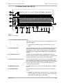
3.2 Rear Panel
1
NR REMOTE
AMP REMOTE 13 - 24CH
2
AMP REMOTE 1 - 12CH
INPUT
CH24
CH23
CH22
CH21
CH20
CH19
CH18
CH17
CH16
CH15
CH14
CH13
CH12
CH11
CH10
CH9
CH8
CH7
CH6
CH5
CH4
CH3
CH2
CH1
3
OUTPUT
EXT CLOCK
PARALLEL 1/0
SERIAL 1/0
REMOTE
AUTO LOCATOR
POWER
GROUND
7
5
4
6
8
10
9
Figure 3-2
Rear Panel Features
NOTE: Numbers in brackets [ ] refer to Figure 3-2.
[1] NR REMOTE Connector
This connector is used to provide mode control of any non-simultaneous
external noise reduction system which requires machine control of
Encode/Decode modes.
[2] AMP REMOTE Connectors
This connector is used to connect the optional Amplifier Remote Controller.
[3] Audio Input/Output Connectors
Connectors for audio input and output.
[4] EXT CLOCK Connector
Used to connect an external reference clock to control the capstan speed of
the MTR-90III.
October 1990
3-5
Section 3 Controls and Indicators
MTR-90III Operation and Maintenance Manual
[5] PARALLEL I/O Connector
This is a standard Otari parallel I/O interface connector.
[6] SERIAL I/O Connector
These connectors provide serial remote control of transport and audio
channel modes.
[7] REMOTE Connector
This connector is used for Remote Controllers (e.g., CB-147).
[8] AUTO LOCATOR Connector
This connector is used for the CB-148 Auto Locator.
[9] POWER Connector
This connector is the AC power input connector.
[10] GROUND Terminal
This is the ground terminal.
3-6
October 1990
MTR-90III Operation and Maintenance Manual
Section 3 Controls and Indicators
3.3 Remote Control Unit (CB-147)
11
ALL SAFE
10
1
2
3
4
5
6
7
8
9
10
11
12
13
14
15
16
17
18
19
20
21
22
23
24
1
2
3
4
5
6
7
8
9
10
11
12
13
14
15
16
17
18
19
20
21
22
23
24
READY
SAFE
9
ALL INPUT
ALL SEL-REP
ALL REPRO
7
INDIVIDUAL
INPUT
8
SEL-REP
REPRO
6
VARI
FIX
EXT
SPEED
DISPLAY
PITCH CONTROL
HI
IPS
LO
%
DOWN
CUE
RECORD
PLAY
STOP
CB-147
5
4
3
RWD
F.FWD
UP
REMOTE CONTROL UNIT
2
1
Figure 3-3
Remote Control Unit Features
NOTE: Numbers in brackets [ ] refer to Figure 3-3.
[1] PLAY/STOP/RWD/F.FWD/RECORD/CUE Buttons
These buttons have the same function as the corresponding buttons on the
MTR-90III (see §3.1).
❑
The CUE button on the Remote Control can be used only for Lifter
Defeat.
[2] PITCH CONTROL Knob
The PITCH CONTROL knob is used to vary the tape speed from the selected
tape speed over a range of approximately ±20% when the Speed Mode
switch [6] has been set to VARI. The varied tape speed can be displayed on
the Speed Display screen [4] when the SPEED DISPLAY button [5] has been
pressed.
[3] %-IPS Button/Indicators
This button switches the Speed Display screen [4] between inches per
second (ips) and percentage of the selected tape speed (%). The appropriate
indicator will illuminate to indicate which mode has been selected.
[4] Speed Display Screen/Indicators
This four digit speed display screen shows the current tape speed in either
ips or percentage of the change from the selected speed as determined by
the %-IPS Switch [3]. The SPEED DISPLAY button [5] must be first pushed to
view this variation. This screen also contains the HI-LO indicators for
showing the selected tape speed.
[5] SPEED DISPLAY Button
The SPEED DISPLAY button is used to turn the Speed Display screen [4] on
and off.
[6] Speed Mode Switch
The Speed Mode switch gives a choice of three references for tape speed
control.
❑
October 1990
FIX Mode: The capstan speed is fixed by reference to an internal crystal
oscillator at either 15 ips (38 cm/s) or 30 ips (76 cm/s) selected by the
TAPE SPEED button (§3.1, [2]) on the MTR-90III.
3-7
Section 3 Controls and Indicators
[7] INDIVIDUAL Button
MTR-90III Operation and Maintenance Manual
❑
VARI Mode: The capstan speed can be varied through a range of just
over ±20%, almost four musical steps, as set by the adjacent PITCH
CONTROL knob [2]. The speed variation is indicated on the Speed
Display screen [4] in percent or ips. The SPEED DISPLAY button [5]
must be pushed to view this variation. The speed is varied from the
speed set by the TAPE SPEED button (§3.1, [2]) on the MTR-90III.
❑
EXT Mode: The capstan speed can be varied by reference to an external
oscillator, synchronizer, etc.
When the INDIVIDUAL button is engaged, the 3-position Output Selector
Switches [8] independently determine the signal source for each of the
MTR-90III channel output amplifiers, VU meters, and output jacks unless the
channel is in Ready mode. The individual channel switches can be overridden
by the master ALL INPUT, ALL SEL·REP or ALL REPRO buttons.
[8] Output Selector Switches/Mode Indicators
These 3-position switches select the source for the output signal. The column
of 3 LEDs above each switch indicates the selected status.
❑
INPUT Mode: With the Output Selector switches set to the INPUT
position (lever up), the input electronics, not the tape, are monitored
whether the machine is in Stop, Play or Record mode. The amber
indicator (top row) for the channel illuminates.
❑
SEL·REP Mode: With the Output Selector switches set to the to the
SEL·REP position (lever centered), the channel output consists of the
tape playback picked up with the record head and amplified via the sync
amp for that channel. The green indicator (middle row) for the channel
illuminates.
❑
REPRO Mode: With the Output Selector switches set to REPRO position
(lever down), the output signal is playback driven from the reproduce
head and reproduce electronics. The corresponding amber indicator
(bottom row) should be illuminated.
[9] ALL INPUT/ALL SEL·REP/ALL REPRO Buttons
When switching all channels to one of the three possible modes, the master
ALL INPUT, ALL SEL·REP or ALL REPRO push buttons can be used instead
of the 24 Output Selector switches. These buttons override the individual
Output Selector Switches [8].
3-8
❑
All Input Mode: When the ALL INPUT button has been pressed, all of the
channels enter Input mode, and the amber indicator to the left and all 24
amber LEDs to the right of this button illuminate. See Table 3-1.
❑
All Sel·Rep Mode: When the ALL SEL·REP button has been pressed, all
of the channels are set into Sel·Rep mode, and the green indicator to the
left and the green LEDs to the right (middle row) or the amber LEDs (top
row) illuminate, depending on whether the machine is in Stop, Play or
Record mode and on the Ready/Safe status of the individual channels.
See Table 3-1.
❑
All Repro Mode: When the ALL REPRO button has been pressed, all of
the channels are set into Repro mode, and the amber indicator to the left
and the amber LEDs to the right (bottom row) or the amber LEDs (top
row) illuminate, depending, as in the case of the ALL SEL·REP button, on
whether the machine is in Stop, Play or Record mode and on the
Ready/Safe status of the individual channels. See Table 3-1.
October 1990
MTR-90III Operation and Maintenance Manual
[10] READY/SAFE Switches/Indicators
Section 3 Controls and Indicators
These 2-position switches are provided for setting individual channels in
Record Ready or Record Safe mode. The red indicators above illuminate
when that READY/SAFE switch is set to READY, indicating that the
corresponding channel is ready for recording. The READY/SAFE switches can
be overridden by the ALL SAFE switch [11].
NOTE: There is a functional interaction of the READY/SAFE switches [10] and
the output select switches. The output status and indicator indicators also
change in some cases, as noted, when the machine is switched between Stop
and Play modes.
[11] ALL SAFE Switch/Indicator
This switch is used to select between putting all channels in Record Safe
mode all at once or allowing the mode to be selected by the READY/SAFE
switches [10] on the individual channels.
❑
Setting this switch to the ALL SAFE position puts all channels into
Record Safe mode and illuminates the adjacent red ALL SAFE indicator.
In All Safe mode, the individual READY/SAFE switches for each channel
have no effect and the indicators above them should be off.
❑
When ALL SAFE is not selected, the Record Ready status of each
channel is determined by its READY/SAFE switch.
Table 3-1
Table of Monitor Output Modes
Transport Mode
Output
Mode
Ready/
Safe
Stop
Play
Record
Fast Wind
Sel·Rep
Sel·Rep
Repro
Repro
Input
Input
Ready
Safe
Ready
Safe
Ready
Safe
Input 1
Sel·Rep
Input 1
Repro
Input
Input
Sel·Rep
Sel·Rep
Repro
Repro
Input
Input
Input
Sel·Rep 4
Repro
Repro 4
Input
Input 4
Input 2, 3
Sel·Rep
Input 2, 3
Repro
Input
Input
Stop Standby mode.
Fast Standby mode.
3
Pressing the Cue button places the transport into Sel·Rep mode.
4
No recording can take place while the transport is in Safe mode.
1
2
October 1990
3-9
Section 3 Controls and Indicators
MTR-90III Operation and Maintenance Manual
3.4 Auto Locator (CB-148)
1
2
TAPE TIME
LOCATE TIME
STOP WATCH
RESET
H
0
M
1
RESET
S
2
3
19
H
3
4
5
6
M
7
RESET
ALL
CLEAR
S
8
18
M
S
STOP
START/LAP
9
STORE
4
17
SEARCH
7 8 9
SEARCH
ZERO
ZERO SET
RECORD
SEARCH
PLAY
SHUTTLE
STOP
REW
AUTO
REWIND
4 5 6
F.FWD
1 2 3
0
STO
CB-148
16
15
14
13
12
5
6
LOAD
7
8
RCL
AUTO LOCATOR
9
10
11
Figure 3-4
Auto Locator Front Panel Features
NOTE: The CB-148 Auto Locator is an option. It should be installed as
detailed in §2.3 and § 2.4. Numbers in brackets [ ] refer to Figure 3-4.
The function buttons [11] have 2-level illumination: dim (normal) and bright
(when selected). The 10-Key Pad [4] and the related buttons [5]–[10] do not
illuminate.
[1] TAPE TIME (Tape Time Readout/Reset Button)
The Tape Time readout displays the elapsed time of the tape relative to the
same zero point shown on the MTR-90III Tape Time Counter display (§3.1,
[1]) or any other point on the tape such as the beginning of a take. The Tape
Time readout is also provided with a minus sign at the head of digital
readouts when the elapsed time diminishes from 0.00.00, that is, just before
0.00.00, -0.00.00 is displayed. The same applies to LOCATE TIME [2].
3 - 10
❑
Resetting the Tape Time Readout: Press the RESET button adjacent to
the Tape Time readout to reset the Tape Time readout.
❑
Offsetting the Tape Time Readout: To offset the Tape Time readout
from the MTR-90III Tape Time Counter display, select a Locate Time and
press the Shift Left button [5].
❑
Correlating the Tape Time Readout: To correlate the Tape Time with the
MTR-90III Tape Time Counter display, press the LOAD [6] or SEARCH
ZERO button [15].
October 1990
MTR-90III Operation and Maintenance Manual
Section 3 Controls and Indicators
[2] LOCATE TIME (Locate Time Readout/RESET Button)
The Locate Time readout displays the tape time destination when the
SEARCH [14], SHUTTLE [13], or AUTO REWIND [12] buttons have been
pressed. The Locate Time readout is also provided with a minus sign at the
head of digital readouts when the elapsed time diminishes from 0.00.00, that
is, just before 0.00.00, -0.00.00 is displayed.
❑
Entering Locate Times: There are three methods for entering Locate
Time.
1. Locate Times can be entered directly from the 10-Key Pad [4].
2. Locate Times can be recalled from previously stored cues using the
RCL button [8] and a number on the 10-Key Pad [4].
3. Locate Times can be “copied” from the Tape Time readout by
pressing the Shift Right button [7].
❑
Resetting the Locate Time Readout: Press the RESET button adjacent
to the Locate Time readout to reset the Locate Time.
[3] STOP WATCH (Stop Watch Readout/START LAP Button/STOP Button/RESET Button)
The Stop Watch is independent and has no interaction with other Auto
Locator or MTR-90III functions. The readout displays up to 99M59S.
[4] 10-Key Pad
❑
Starting the Stop Watch: When the transport is in Stop mode, press the
START LAP button under the Stop Watch readout to start the watch.
❑
Taking Lap Times: When the START LAP button is pressed a second
time, the lap time (the time at the instant the button is pressed) is
displayed. To return to the elapsed time count, press START/LAP again.
❑
Stopping the Stop Watch: Press the STOP button located next to the
START LAP button to stop the counting and display the final time. If
STOP is pressed while a lap time is displayed, the readout will change
and display the final time.
❑
Resetting the Stop Watch: Press the RESET button adjacent to the Stop
Watch readout to reset the Stop Watch. If the RESET button is pressed
while the watch is counting, the count will be stopped.
These keys are used to enter Locate times or a Cue point memory register
numbers. The 10-Key Pad is temporarily disabled while the machine is
performing a Search, Search Zero, Shuttle or Auto Rewind function.
❑
Clearing Cue Memories: By entering a Locate Time of 0.00.00 and
pressing STO and a number for a Cue Memory, that Cue memory will be
cleared (0.00.00 will be stored).
NOTE: It is impossible to enter a Locate Time with a numeral of 6 or higher in
the second digit from the right since this would be 60 or more seconds.
[5] SHIFT LEFT Button (
[6] LOAD Button
October 1990
)
This button transfers the time shown on the Locate Time readout [2] to the
Tape Time readout [1].
The LOAD button changes the Tape Time readout to display the same tape
time shown on the MTR-90III Tape Time Counter Display (§3.1, [1]). In other
words, it resets the Auto Locator Tape Time to correspond to the actual time
shown on the transport.
3 - 11
Section 3 Controls and Indicators
[7] SHIFT RIGHT Button (
)
MTR-90III Operation and Maintenance Manual
This button transfers the time shown on the Tape Time readout [1] to the
Locate Time readout [2].
NOTE: Tape Time can be stored “on the fly” while the tape is playing or
recording by pressing SHIFT RIGHT at the exact instant to be recorded and
then pressing STO followed by a numeric address.
[8] RCL Button
This button is used to retrieve times previously stored and display it in the
Locate Time readout. When the machine is first turned on, all addresses are
initialized to 00M00S
❑
[9] STO Button
[10] +/– Button
Recalling Cue Points: To recall a given cue point, press the RCL button
and then press the number on the 10-Key Pad [4] (0–9) which identifies
the address where the time is stored. The time will be displayed on the
Locate Time readout [2] and will also remain in memory. Repeat to recall
another cue. It is not necessary to reset the readout since the recalled
time will replace any previously displayed Locate Time.
This button is used to memorize the time displayed on the Locate Time
readout [2]. Up to ten different times can be memorized at once. Memory is
volatile, meaning it is not saved after the power is turned off.
❑
Storing Cue Points: To store a given cue point, display the time in the
Locate Time readout either by direct entry with the 10-Key Pad [4] or by
using the SHIFT RIGHT button [12]. Press the STO button and then
press a number on the 10-Key Pad (0–9) [4]. The number pressed
becomes the “address” where the Locate Time is stored. To store a
second cue, repeat using a different address. If the same address is
used, the previously stored time will be erased.
❑
Clearing Cue Memories: By entering a Locate Time of 0.00.00 and
pressing STO and a number for a Cue Memory, that Cue memory will be
cleared (0.00.00 will be stored).
When this button is pressed once, a minus (–) appears at the head of the
Locate Time readout. When pressed again, a plus (+) sign appears.
[11] RECORD/PLAY/STOP/RWD/F.FWD Buttons
These buttons essentially duplicate the functions of their counterparts on the
MTR-90III Transport (§3.1) and Remote Control Unit (§3.3). The only
difference is that when using Search, Search Zero, Shuttle, and Auto Rewind
modes, the Auto Locator PLAY and/or RECORD buttons can be pressed
without affecting the selected Auto Locator mode; pressing the RECORD or
PLAY buttons on the MTR-90III or Remote Control Unit will override the Auto
Locator function.
[12] AUTO REWIND Button
3 - 12
AUTO REWIND is similar to Shuttle [13], except the tape will play to the
Locate Time, rewind and stop at the point where the AUTO REWIND button
was first pressed rather than continue the play/rewind cycle.
October 1990
MTR-90III Operation and Maintenance Manual
[13] SHUTTLE Button
Section 3 Controls and Indicators
Pressing the SHUTTLE button causes the MTR-90III to “remember” the
current Tape Time displayed on the readout and to enter (or continue in) Play
mode until the Locate Time is reached. Then the tape automatically rewinds
to the point where SHUTTLE was first pressed and plays again. This cycle
continues until Shuttle mode is exited. Shuttle mode is helpful for playing a
section of an alignment tape, for rehearsing a particular segment of a tune,
and so forth.
NOTE: These explanations assume that the Locate Time is greater than the
displayed Tape Time. If not, the SHUTTLE will enter Reverse Shuttle mode
stopping the tape when the button is pressed and rewinding the tape to the
time displayed in the Locate Time display and then going into Play mode and
repeating this cycle until cancelled.
❑
Starting Shuttle Mode: Enter a Locate Time (ahead in time) for the end
point of the shuttle operation. Move the tape to the point where the
shuttle operation is to begin; the transport may be in Stop, Play, or
Record mode at this point. Press the SHUTTLE button.
❑
Recording During Shuttle Mode: To enter Record mode at any time
while the tape is playing in Shuttle mode, press the RECORD button [11]
on the Auto Locator. The machine will continue recording for the
duration of that “pass” but will return to Play mode after it rewinds to the
beginning of the shuttle segment.
NOTE: Unlike Search [14] and Search Zero [15] modes, the machine cannot
be “preset” to begin Recording by pressing RECORD [11] while the tape is
rewinding in Shuttle mode. Shuttle/Record mode works only when the Auto
Locator RECORD button is pressed. Pressing the RECORD button on the
Remote Control Unit or MTR-90III ends the shuttle and immediately causes
the machine to enter normal Record mode.
❑
[14] SEARCH Button
Exiting Shuttle Mode: To end (“abort”) a Shuttle, press STOP, RWD or
F.FWD on the Auto Locator or the MTR-90III transport; or the PLAY
button on the Remote Control Unit or on the transport.
Pressing the SEARCH button causes the MTR-90III to fast wind (or rewind)
the tape until the Auto Locator Tape Time matches that shown on the Locate
Time readout [3]. There are three variations of Search mode:
❑
Search/Stop: Pressing SEARCH will move the tape to the Locate Time
and then stop the transport.
❑
Search/Play: Pressing the SEARCH and PLAY [11] buttons causes the
PLAY button to flash and the tape to wind to the Locate Time. The
transport enters Play mode and the PLAY button will remain brightly
illuminated.
❑
Search/Record: Pressing the SEARCH and then the PLAY and RECORD
[11] buttons causes the PLAY and RECORD buttons to flash and the tape
to wind to the Locate Time and enter Record mode.
NOTE: Search/Play (Search/Record) mode functions only when the PLAY
button (or PLAY and RECORD buttons) on the Auto Locator is pressed.
Pressing this button (these buttons) on the Remote Control Unit or on the
transport ends the search and causes the machine to enter Play (Record)
mode.
❑
October 1990
Ending Search: To end (“abort”) a Search press STOP, REWIND or FAST
FORWARD on the Auto Locator; their counterparts on the MTR-90III
transport; or the PLAY button on the Remote Control Unit or on the
transport.
3 - 13
Section 3 Controls and Indicators
[15] SEARCH ZERO Button
MTR-90III Operation and Maintenance Manual
Pressing the SEARCH ZERO button causes the MTR-90III to return at fast
wind (or rewind) speed to the 0.00.00 Tape Time shown on the MTR-90III
Tape Time readout. There are three variations of Search Zero Mode.
NOTE: If the Auto locator Tape Time readout has been changed to a different
zero from the MTR-90III, it will reset to match the MTR-90III the moment
SEARCH ZERO is pressed. Search Zero always searches for the zero of the
MTR-90III Tape Time display.
❑
Search Zero/Stop: Pressing the SEARCH ZERO button will wind the tape
to zero Tape Time and then stop the transport.
❑
Search Zero/Play: Pressing the SEARCH ZERO and PLAY [11] buttons
causes the PLAY button to flash and the tape to wind to zero Tape Time.
The transport enters Play mode and the PLAY button will remain brightly
illuminated.
❑
Search Zero/Record: Pressing the SEARCH ZERO and then the PLAY
and RECORD [11] buttons causes the PLAY and RECORD buttons to
flash and the tape to wind to the zero point and enter Record mode.
NOTE: Search Zero/Play (Search Zero/Record) mode functions only when the
PLAY button (or PLAY and RECORD buttons) on the Auto Locator is pressed.
Pressing this button (these buttons) on the Remote Control Unit or on the
transport ends the search and causes the machine to enter Play (Record)
mode.
❑
Ending Search Zero: To end (“abort”) a Search Zero, press STOP,
REWIND or FAST FORWARD on the Auto Locator; their counterparts on
the MTR-90III transport; or the PLAY button on the Remote Control Unit
or on the transport.
[16] ZERO SET Button
This button is used to automatically reset both the MTR-90III and the Auto
Locator Tape Time readouts to zero at a specific point on the tape (see
§4.3.10.)
[17] SEARCH 0–9 Buttons/Indicators
When moving the tape directly to the memorized location, press the SEARCH
0–9 button of the memory in which the location has been memorized. The
tape moves automatically to the position.
[18] STORE 0–9 Buttons/Indicators
When one of these buttons is pressed, the tape time displayed in the Locate
Time readout will be stored into the memory of the button pressed. When the
indicator for a STORE 0–9 button is illuminated, it indicates that a tape time
is stored in its memory and that STORE 0–9 button is ineffective. Up to ten
tape times can be stored.
❑
[19] ALL CLEAR Button
3 - 14
Clearing Cue Memories: Pressing the STORE 0–9 button for any
memory twice within one second will clear that memory.
Pressing the ALL CLEAR button twice within one second will clear all Cue
Memories.
October 1990
Section 4 Operation
This section contains a list and an accompanying explanation of each of the
operating conditions (or modes) of the MTR-90III and detailed instructions
describing each mode of operation. All portions of this section should be
read when first becoming familiar with the machine and then again as a guide
while learning to operate the machine. The Table of Operating Modes
provides a quick reference, and the detailed portion provides in depth
instructions about how to operate the machine. Information regarding
installation and set-up of the machine is contained in Section 2 of this
manual. If unpacking and hooking up the machine for the first time, please
refer to Section 2 before continuing with this section.
OTARI recommends situating the Remote Control Unit (and the optional Auto
Locator) in a convenient location near the mixing console.
4.1 Modes of Operation . . . . . . . . . . . . . . . . . . . . . . . . . . . . . . . . . . . . . . . . . . . . . . . . 4-2
4.2 Record and Play Modes . . . . . . . . . . . . . . . . . . . . . . . . . . . . . . . . . . . . . . . . . . . 4-3
4.2.1
4.2.2
4.2.3
4.2.4
4.2.5
4.2.6
Threading the Tape on the Machine . . . . . . . . . . . . . . . . . . . . . . . . . . . . . . . 4-3
Recording Initial Tracks . . . . . . . . . . . . . . . . . . . . . . . . . . . . . . . . . . . . . . . . . . 4-4
Playback of Initial Tracks . . . . . . . . . . . . . . . . . . . . . . . . . . . . . . . . . . . . . . . . . 4-5
Sel·Rep Recording (Overdubbing) . . . . . . . . . . . . . . . . . . . . . . . . . . . . . . . . 4-5
Sel·Rep Recording (Punch-Ins) . . . . . . . . . . . . . . . . . . . . . . . . . . . . . . . . . . . 4-6
Rehearsal of Overdubs and Punch-Ins . . . . . . . . . . . . . . . . . . . . . . . . . . . . 4-7
4.2.6.1 Rehearsal of Overdubs . . . . . . . . . . . . . . . . . . . . . . . . . . . . . . . . . . . . 4-7
4.2.6.2 Rehearsal of Punch-Ins . . . . . . . . . . . . . . . . . . . . . . . . . . . . . . . . . . . . 4-7
4.2.7 Mixdown . . . . . . . . . . . . . . . . . . . . . . . . . . . . . . . . . . . . . . . . . . . . . . . . . . . . . . . . . 4-8
4.2.8 Cue Modes . . . . . . . . . . . . . . . . . . . . . . . . . . . . . . . . . . . . . . . . . . . . . . . . . . . . . . . 4-8
4.2.8.1 Normal Cue Mode . . . . . . . . . . . . . . . . . . . . . . . . . . . . . . . . . . . . . . . . . 4-8
4.2.8.2 Fast Cue Mode (Lifter Defeat) . . . . . . . . . . . . . . . . . . . . . . . . . . . . . . 4-8
4.2.9 Spot Erasure . . . . . . . . . . . . . . . . . . . . . . . . . . . . . . . . . . . . . . . . . . . . . . . . . . . . . 4-9
4.2.10 Variable Speed Mode . . . . . . . . . . . . . . . . . . . . . . . . . . . . . . . . . . . . . . . . . . . . 4-9
4.2.11 External Speed Reference . . . . . . . . . . . . . . . . . . . . . . . . . . . . . . . . . . . . . . 4-10
4.3 Auto Locator Operation . . . . . . . . . . . . . . . . . . . . . . . . . . . . . . . . . . . . . . . . . . 4-10
4.3.1 Entering Locate Times . . . . . . . . . . . . . . . . . . . . . . . . . . . . . . . . . . . . . . . . . .
4.3.2 Storing Cue Points . . . . . . . . . . . . . . . . . . . . . . . . . . . . . . . . . . . . . . . . . . . . . .
4.3.3 Recalling Cue Points . . . . . . . . . . . . . . . . . . . . . . . . . . . . . . . . . . . . . . . . . . . .
4.3.4 Clearing Cue Points . . . . . . . . . . . . . . . . . . . . . . . . . . . . . . . . . . . . . . . . . . . . .
4.3.5 Search . . . . . . . . . . . . . . . . . . . . . . . . . . . . . . . . . . . . . . . . . . . . . . . . . . . . . . . . . .
4.3.6 Search Zero . . . . . . . . . . . . . . . . . . . . . . . . . . . . . . . . . . . . . . . . . . . . . . . . . . . .
4.3.7 Shuttle . . . . . . . . . . . . . . . . . . . . . . . . . . . . . . . . . . . . . . . . . . . . . . . . . . . . . . . . .
4.3.8 Auto Rewind . . . . . . . . . . . . . . . . . . . . . . . . . . . . . . . . . . . . . . . . . . . . . . . . . . . .
4.3.9 Setting the Tape Time Readout (Offset Mode) . . . . . . . . . . . . . . . . . . . .
4.3.10 Zero Set . . . . . . . . . . . . . . . . . . . . . . . . . . . . . . . . . . . . . . . . . . . . . . . . . . . . . . .
4.3.11 Stop Watch . . . . . . . . . . . . . . . . . . . . . . . . . . . . . . . . . . . . . . . . . . . . . . . . . . . .
October 1990
4-10
4-11
4-11
4-12
4-12
4-13
4-14
4-14
4-15
4-15
4-15
4-1
Section 4 Operation
MTR-90III Operation and Maintenance Manual
4.1 Modes of Operation
CAUTION: The reel motor on the MTR-90III supplies a powerful torque force.
When a tape is threaded on the machine, do not touch the reel or tension
arm. When the machine is in Fast Wind mode, exercise caution to keep hair,
clothing, jewelry, fingers, etc., away from the reel. When the operations are
controlled from the Remote Control, precautionary measures are important.
It is imperative that the swing arms are not pressed directly when a tape is
threaded. To shuttle the tape back and forth slowly, do not attempt to move
the reels by hand. Instead, place the transport in Stop mode and turn the top
of the capstan by hand or press the MTR-90III CUE button and move the
adjacent Cue Wheel.
In the following table, mode names in parenthesis indicate that the MTR-90III
must be in the indicated mode before the designated button is pressed. For
example, to enter Unload mode: (Stop) + UNLOAD means the MTR-90III
must be in Stop mode before the UNLOAD button is pressed.
Table 4-1
Modes of Operation
MODE
CONTROL
OPERATION
Play
PLAY
Tape plays from Supply to Take-up at the selected speed.
Record
PLAY+RECORD or (Play)+RECORD
Any channel in Record Ready begins to record as tape moves
from Supply to Take-up.
Stop
STOP
Tape motion stops.
Fast Forward
F.FWD
Tape moves from Supply reel to Take-up reel at fast wind speed.
Rewind
REWIND
Tape moves from Take-up reel to Supply reel at fast wind speed.
Load
(Unload)+STOP
Both reels turn to remove any slack in the tape and the tension
servo system is activated.
Unload
(Stop)+UNLOAD
Tension servo system is deactivated.
Normal Cue Mode
(Stop)+CUE+Cue Wheel
Tape motion is proportional to the amount the Cue Wheel is
turned.
Fast Cue Mode (Lifter Defeat) (Fast Wind)+CUE
The tape lifters are retracted to allow audio monitoring.
Spot Erase
The tape can be moved by hand for erasure of small areas of
tape.
4-2
SPOT ERASE
October 1990
MTR-90III Operation and Maintenance Manual
Section 4 Operation
4.2 Record and Play Modes
If there are any unusual sounds, mechanical malfunctions or strange odors
during the following procedures or if anything seems to be abnormal,
immediately turn off the POWER switch, unplug the AC cord and inspect the
machine to determine the cause. If in doubt as to the cause or severity of the
problem after consulting the appropriate section of this manual, contact the
nearest OTARI representative or the OTARI technical service department for
assistance.
NOTE: If the MTR-90III is set up with a 16 channel (8-channel) head
assembly, disregard all Remote Control Unit switches for channels 17-24 (924).
4.2.1 Threading the Tape on the Machine
1. Unlock the reel tables so they will accommodate a reel hub by lifting up
the clamp levers on top.
2. Place a reel on the Reel Table and lower the clamp levers to secure the
reel to the Reel Table.
NOTE: There is a locating pin near the bottom of each reel table. In order for
the reel to seat firmly against the reel table, be sure one of the slots in the
reel hub is aligned with the locating pin. To lock reel to reel table, push down
on clamp level until it is seated. Failure to observe this precaution will cause
the reel to "float" and may damage the reel and/or the tape.
3. Turn on the power (the POWER switch is behind the front door of the
MTR-90III at the left side near the bottom). The adjacent 8 pilot lights
(Light Emitting Diodes-LEDs) illuminate indicating the different sections
of the power supply are operating. The meter lamps and the lamps in
the transport buttons glow dimly except the TAPE UNLOAD button which
should be brightly illuminated. The Tape Time counter on top of the
head assembly should indicate "0.00.0" in red numerals. This indication
appears several seconds after the power is turned on.
TAPE SPEED
RESET
HI
LOW
UNLOAD
SPOT ERASE
CUE
SHIELD
Figure 4-1
Tape Threading Path
October 1990
4-3
Section 4 Operation
MTR-90III Operation and Maintenance Manual
4. Pull about 120 cm (4') of tape from the reel and thread along the tape
path shown in Figure 4-1 (also imprinted on the MTR-90III deck plate
near the transport buttons). Wind the tape 2 or 3 time around the empty
reel, make sure the tape does not slip and is wound firmly. Do not fold
the end of the tape as the bump created will disrupt the constant servo
tension and create unnecessary swing arm jitter (vibration).
5. Turn both reels in the direction shown by the arrows in Figure 4-1 to
tighten the tape. This will cause the swing arms to retract fully and
"click" into place. Both green LEDs on the REEL CONTROL PCB
Assembly (board #1 in the lower card cage) illuminate.
CAUTION! Hold the reels by the edge of the flange so if the reel motors
should be actuated, the reel can be released without risk to fingers or hands.
6. Press the STOP button. The STOP will be more brightly illuminated than
all the other tape motion push buttons, and both swing arms should
move to approximately mid-position (centered). The reel servos are now
activated, and the tape is under constant tension.
4.2.2 Recording Initial Tracks
1. Thread a blank tape on the transport (§ 4.2.1).
2. Select the desired Tape Speed, HI or LOW. Unless there is some special
application, use the FIX SPEED MODE setting.
3. Reset the Tape Time Counter by pressing the RESET button on the
MTR-90III.
4. Apply a test signal to those inputs to the MTR-90III corresponding to the
tracks to be recorded.
5. On the Remote Control Unit press the ALL INPUT button.
6. On the Remote Control Unit disengage the ALL SAFE switch (adjacent
indicator off) and move the READY/SAFE switches to the READY
position for those channels to be recorded. The indicators for those
channels will flash.
7. Adjust the mixing console buss levels so that the MTR-90III meters are
peaking no higher than between -3 and 0 VU.
NOTE: Monitor the output of the MTR-90III (which is the same as the input)
rather than the buss output of the mixing console.
8. It is good practice to record reference tones at the head of every session
tape for level matching later. Use 700 (or 1 kHz), 100 Hz, and 10 kHz
tones at 0 VU reference level. The tones should not be noise reduction
encoded even if a noise reduction system is being used.
9. When ready to record, press the PLAY and RECORD buttons on the
MTR-90III or the Remote Control Unit. The Ready/Safe indicators will
stop flashing and remain illuminated indicating the selected tracks are
recording.
10. To cease recording on all channels, press the STOP button to stop all
tape motion, or the PLAY button to remove the channels from Record
mode and continue in Play mode. To cease recording on only certain
channels and continue recording on others, move the corresponding
READY/SAFE levers to the Safe position.
4-4
October 1990
MTR-90III Operation and Maintenance Manual
Section 4 Operation
4.2.3 Playback of Initial Tracks
1. Rewind the tape to the beginning of the recording by pressing SEARCH
ZERO on the Auto Locator (if the Tape Timer was reset at the beginning
of the recording session) or by pressing the REWIND button.
2. Set the ALL SAFE switch on the Remote Control Unit to the ALL SAFE
position to avoid accidentally erasing recorded tracks. The ALL SAFE
indicator will become illuminated.
3. Set the Output Selector switches for the recorded tracks to the REPRO
position or press the ALL REPRO button. The REPRO indicator for the
tracks being reproduced will become illuminated.
4. Press the PLAY button. The signal on the tape will be reproduced by the
Reproduce head and fed to the Output connectors.
5. Adjust the monitor level at the mixing console.
4.2.4 Sel·Rep Recording (Overdubbing)
Overdubs are performed when it is necessary to add additional tracks
synchronized with material already recorded on other tracks. During Sel·Rep
(Selective Reproduction) playback the recorded material is reproduced by the
record head making it possible to add (overdub) tracks without delay caused
by the space between the Record and Reproduce heads (as in normal
playback). When overdubs are recorded, the recorded tracks are played in
Sel·Rep and monitored through the mixing console. The new material is then
recorded in synchronization with the existing tracks.
A variation of this technique involves an insert, or punch-in, of new material
to replace or add to a previously recorded track. This method is discussed in
§ 4.2.5 Sel·Rep Recording (Punch-Ins).
NOTE: For rehearsal of an overdub, see § 4.2.6.
1. Press the ALL SEL·REP button on the Remote Control Unit.
2. Move the ALL SAFE switch to its OFF position (adjacent red indicator
off).
3. For the channels to which new material is to be added, set the
READY/SAFE switches to the READY position (red indicator above
flashes). For the other channels (channels not to be recorded), set the
READY/SAFE switches to the SAFE position (red indicator above off).
NOTE: When the tape is stopped, the input of any tracks set to Ready mode
will be monitored unless SW1-2 on the TRANSPORT CONTROL PCB
Assembly is off (see § 2.1 Step 2).
4. Press the PLAY and RECORD buttons to begin recording. The input
signal from the channels being recorded and the signal from the tape
from the record head and sync amp on those tracks not being recorded
will be monitored.
5. To end the recording, press the STOP button. As a further precaution,
engage the ALL SAFE switch to prevent accidental erasure of those
channels set to Ready mode.
October 1990
4-5
Section 4 Operation
MTR-90III Operation and Maintenance Manual
4.2.5 Sel·Rep Recording (Punch-Ins)
Punch-ins are performed when it is necessary to insert new material into a
track that has already been recorded without recording the entire track again.
Punch-ins allow monitoring of previously recorded material on the tracks
selected for recording, right up to the instant the track is put into Record. At
the moment that the track(s) enter Record mode, the MTR-90III switches the
output of the tracks being recorded to Input monitor so that the new material
can be monitored as it is being recorded in synchronization with the material
recorded earlier.
NOTE: For rehearsal of Punch-ins see § 4.2.6.
1. Rewind the tape to a point just before the beginning of the section to be
recorded.
2. Move the ALL SAFE switch to its OFF position (adjacent red indicator off)
and press the ALL SEL·REP button.
3. Set the READY/SAFE switches for all the tracks that are not going to be
recorded to Safe. Set the READY/SAFE switches for the tracks that are
going to be recorded to Ready.
NOTE: When the tape is stopped, the input of any tracks set to Ready mode
will be monitored unless SW1-2 on the TRANSPORT CONTROL PCB
Assembly is off (see § 2.1 Step 2).
4. Begin playback. Listen to the monitor and when the beginning of the
punch-in section is played, press the RECORD button to begin recording.
Best results are obtained by punching-in during a pause on the tracks
being recorded (on the off-beat). The input signal from the channels
being recorded and the signal from the tape from the record head and
sync amp on those tracks not being recorded will be monitored.
NOTE: There is a short delay from the instant the RECORD button is pressed
to the initiation of recording due to the gapless punch-in feature.
5. There are two ways to end the punch-in:
4-6
❑
Press the PLAY button to end the insert but continue monitoring the
tape for a second punch-in.
❑
Press the STOP button to end the recording all punch-ins. Engage
the ALL SAFE switch as a further precaution.
October 1990
MTR-90III Operation and Maintenance Manual
Section 4 Operation
4.2.6 Rehearsal of Overdubs and Punch-Ins
For the overdub and punch-in procedures discussed in § 4.2.4 and § 4.2.5
there was no way to monitor the new input signal unless and until the
machine was recording. It may be desirable to do "dry runs" (i.e., rehearse
the overdub or punch-in) by playing previously recorded tracks through the
record head and sync amps and by monitoring the input of the tracks to be
recorded.
4.2.6.1 Rehearsal of Overdubs
1. Press the INDIVIDUAL button on the Remote Control Unit so the
individual Output Selector switches can be operated.
2. Set the channels to be recorded to Input mode (set switch to INPUT
position) and set the other channels to Sel·Rep mode (set switch to
SEL·REP position).
3. Engage the ALL SAFE switch (adjacent red indicator on). The position of
individual READY/SAFE switches is not significant for this step (although
presetting the switches according to the intended overdub or punch-in
may be useful).
4. Press the PLAY button. The input signal for all rehearsal tracks and the
signal from the record head and sync amp for all other tracks will be
monitored.
5. To end the overdub rehearsal, press the STOP button.
4.2.6.2 Rehearsal of Punch-Ins
1. Press the INDIVIDUAL button on the Remote Control Unit so the
individual Output Selector switches can be operated.
2. Set the channels to be recorded to Input mode (set switch to INPUT
position) and set the other channels to Sel·Rep mode (set switch to
SEL·REP position).
3. Engage the ALL SAFE switch (adjacent red indicator on). The position of
individual READY/SAFE switches is not significant for this step (although
presetting the switches according to the intended overdub or punch-in
may be useful).
4. Set all channels to Sel·Rep mode by pressing the ALL SEL·REP button.
All tracks will be reproduced from the record head and sync amps. At
the instant the punch-in is to be initiated, press the INDIVIDUAL button
to switch the rehearsal tracks to Input mode.
5. There are two ways to end the punch-in rehearsal.
October 1990
❑
If the insert is to be ended but the tape monitoring to be continued
for a second punch-in rehearsal, press the ALL SEL·REP button.
❑
If all punch-in rehearsals are finished, press the STOP button.
4-7
Section 4 Operation
MTR-90III Operation and Maintenance Manual
4.2.7 Mixdown
The procedure for mixdown is the same as for playback of the initial tracks
(§ 4.2.3). Be sure to use the reproduce head (Repro mode) rather than the
record head (Sel·Rep mode) for best quality.
4.2.8 Cue Modes
4.2.8.1 Normal Cue Mode
When the machine is in Stop mode, pressing the CUE button on the
MTR-90III (not on the Remote Control Unit) activates the adjacent Cue
Wheel. The wheel can then be rotated clockwise or counterclockwise to
shuttle the tape between the Supply and Take-up reels for locating cue points,
matching edit points and so forth. The actual tape speed is proportional to
the degree of rotation.
1. Press the CUE button.
2. Turning the Cue Wheel clockwise move the tape in the forward direction.
Turning the Cue Wheel counterclockwise move the tape in the reverse
direction. The triangular indicators near the Cue Wheel indicate the
direction of the tape movement (forward or reverse). Turning the Cue
Wheel further increases the tape speed.
3. Return the Cue Wheel to its original position to stop the tape movement.
In order to exit Cue mode, press the STOP, PLAY, F. FWD or RWD button.
NOTE: If the head shields are up and the tape needs to be seen as it passes
over the heads, press the SHIELD button on the MTR-90III Transport.
NOTE: The above mode can be used for very fast or slow playback of a tape
beyond the ±20% allowed by the Pitch Control described in § 4.2.10.
4.2.8.2 Fast Cue Mode (Lifter Defeat)
This mode permits auditioning of the tape during FAST FORWARD or
REWIND modes by retracting the tape lifters and padding all the audio tracks
by approximately 20 dB.
1. While the machine is in Fast Forward or Rewind mode, press the CUE
button on either the MTR-90III or the Remote Control Unit to retract the
tape lifters.
2. The lifters will remain retracted for as long as the button is held pressed.
Release the button to extend the lifters again.
CAUTION: Be sure the monitor amps are turned off or the volume is down.
Otherwise programs recorded on the tape are reproduced as a high pitch
squeal which could cause damage to loudspeakers. The volume level of the
monitor speaker can be attenuated by setting SW4 on the BIAS CONTROL
PCB Assembly (#7). For details, please refer to Table 2-4 in § 2.1.
4-8
October 1990
MTR-90III Operation and Maintenance Manual
Section 4 Operation
4.2.9 Spot Erasure
The Spot Erase function is available for erasing short lengths of unwanted
tracks.
1. Search for the portion of tape to be erased in Cue mode or by rotating
the top of the capstan motor by hand.
2. Mark the beginning and the end of the portion of the tape to be erased
with a grease pen.
3. Press the STOP button.
4. Set the READY/SAFE switch to the READY position for the channel to be
erased. Set all other channels to SAFE.
5. Press the SPOT ERASE button. (The SPOT ERASE and STOP lamps will
blink.)
6.
Move the tape slowly by rotating the top of the capstan motor by hand.
7. Press the CUE button just before the beginning of the portion to be
erased reaches the erase head. (Keep pressing both the SPOT ERASE
and CUE buttons. Both lamps will illuminate.)
8. Keep the tape moving until the end of the portion to be erased comes in
front of the erase head, then release the buttons. (Continue moving the
tape slowly for an instant.)
9. The erase current slowly diminishes thus leaving no noise on the tape.
4.2.10 Variable Speed Mode
By setting the Speed Mode Selector on the CB-147 Remote Control to VARI,
the Record/Playback tape speed can be adjusted from the selected speed
over a range of approximately ±20% (approx. ±2 tones). The actual tape
speed can be calculated by multiplying the selected tape speed by the
percentage of variation indicated on the PITCH CONTROL digital readout and
adding or subtracting that value from the base speed; or it can be read
directly from the Speed Display screen when the SPEED DISPLAY switch is
set to the IPS position (press the SPEED DISPLAY button to turn on the
Speed Display screen). Variable speed can used to "tune up" new or old
tracks during overdubs, to change tempos, to bring a song into vocalist's
range, to squeeze or stretch a program to fit a particular time slot, etc.
1. Set the Speed Mode Selector switch on the Remote Control unit to the
VARI position.
2. Use the PITCH CONTROL on the Remote Control unit to vary the capstan
speed as desired. Turning the PITCH CONTROL counter-clockwise
causes the speed to decrease, turning it clockwise causes the speed to
increase.
3. To exit Vari mode, set the Speed Mode Selector switch to the FIX
position.
October 1990
4-9
Section 4 Operation
MTR-90III Operation and Maintenance Manual
4.2.11 External Speed Reference
An external clock (reference oscillator) can be used to control the speed of
the MTR-90III capstan motor. When the SPEED MODE switch is set to EXT
position, a suitable input signal must be applied to P/N18 of the EXT CLOCK
input connector (a 25 pin Honda connector on the MTR-90III rear panel) or
P/N20 of the Parallel I/O Connector (37 pin connector on the MTR-90III rear
panel). The reference frequency is 9,600 Hz, and should be at TTL level (0 V
low, +5 V high), approximately a 50% duty cycle; a sine wave source may be
used at a level of about 10 Vp-p. Do not feed 9.6 kHz signals to the EXT
CLOCK and PARALLEL I/O connectors at the same time.
When the external reference is in use, the HIGH/LOW SPEED SELECT switch
still operates although tape speeds (15/30 ips or 7.5/15 ips) vary
proportional to the deviations of the clock input from the reference frequency.
When using SMPTE time code synchronizers, the SMPTE-CUE slide switch
(on the back of the upper card cage mother board near the #24 card
connector) should be turned on to activate Lifter Defeat. If the MTR-90III is
being used for 16 track operation, a jumper cable will have to be installed to
join the 3-pin Molex connector adjacent to this switch to a similar connector
on the same circuit board located between the #16 and #17 card connectors
(#8 and #9 for 8 track operation).
Detailed information on using time code synchronizers with the MTR-90III is
available from the manufacturer of the equipment or by contacting OTARI.
4 - 10
October 1990
MTR-90III Operation and Maintenance Manual
Section 4 Operation
4.3 Auto Locator Operation
The OTARI CB-148 Auto Locator is designed specifically for the MTR-90III. It
uses a microcomputer for sophisticated, precision control of tape motion
without overshoot. The tape time memory stores up to 10 cue points (11 if
search zero is also considered) which can be directly memorized by pressing
only one button instead of being keyed in and can be directly recalled
instantly by pressing another button. And there is an independent digital
built in stop-watch. Each memory and readout can accommodate times of
up to 9H59M59S. In addition to special Auto Locator functions such as
Search, Search Zero, Zero Set, Shuttle and Auto Rewind (described in
subsequent paragraphs), there is a duplicate set of tape transport control
buttons like those on the Remote Control Unit and transport. The CB-148
Auto Locator should be installed as detailed in § 2.3 and § 2.4. The front
panel features of the Auto Locator are briefly described in § 3.3.
4.3.1 Entering Locate Times
The Locate Time readout displays the tape time to be located when the
SEARCH, SHUTTLE or AUTO REWIND buttons are pressed. There are 3 ways
to enter Locate times:
❑
Locate times can be entered directly from the 10-Key pad. Negative
locate times can be entered with the +/- button.
❑
Locate times can be recalled from stored tape locations or cues (see
§ 4.3.3).
❑
Locate time can be "copied" from the Tape Time readout by pressing the
SHIFT RIGHT button.
NOTE: It is impossible to enter a locate time with a numeral of 6 or higher in
the tens digit for minutes or seconds.
4.3.2 Storing Cue Points
There are two ways to store cue points into the Auto Locator memory. Both
methods store the tape time displayed on the Locate Time readout and not
the time on the Tape Time readout.
❑
Storing with the STORE 0-9 Buttons (Direct Store): The tape time can
be directly stored in memory without using the 10-Key Pad. Up to ten
memories can be stored just by pressing a button with an dark indicator.
1. To store a given cue, display the desired cue point time in the Locate
Time readout (refer to § 4.3.1).
2. Press a STORE 0-9 button with an dark indicator. The number pressed
(0 through 9) becomes the "address" where the Locate Time is stored. If
an indicator is illuminated, a tape location has already been stored in that
memory and that STORE 0-9 button is inoperable.
3. To store a second cue, repeat Steps 1 and 2 using a different address.
The same address or the address of a memory with a tape location
stored cannot be used.
NOTE: To use this method when an address already has a tape time stored,
the memory must first be erased before proceeding.
October 1990
4 - 11
Section 4 Operation
MTR-90III Operation and Maintenance Manual
❑
Storing with the STO Button and the 10-Key Pad: The STO button is
used to memorize the time displayed in the Locate Time readout. Up to
ten different times can be stored at once. Memory is volatile, meaning it
is not saved after the power is turned off.
1. To store a given cue, display the desired cue point time in the Locate
Time readout (refer to § 4.3.1).
2. While holding the the STO button down, press any one of the 10 numeric
keys on the 10-Key Pad. The number pressed (0 through 9) becomes
the "address" where the Locate Time is stored.
3. To store a second cue, repeat Steps 1 and 2 using a different address. If
the same address is re-used, the previously stored time will be replaced
by the new entry.
NOTE: Tape Time can be "captured" "on the fly" while the tape is playing or
recording by pressing SHIFT RIGHT at the exact time to be recorded and then
pressing STO followed by a numeric address or by pressing a STORE 0-9
button.
4.3.3 Recalling Cue Points
The RCL button is used to retrieve a time which was previously stored and
display it in the Locate Time readout. When the machine is first turned on, all
addresses are initialized so they contain 00.00.
1. To recall a given cue, press the RCL button and then press the numeric
key (0 through 9) which identifies the "address" where the time was
stored. The time will display on the Locate Time readout and will also
remain in memory.
2. To recall another cue, Repeat Step 1. It is not necessary to first reset the
readout since the recalled time will replace any previously displayed
Locate Time.
4.3.4 Clearing Cue Points
There are several methods to clear the memories.
4 - 12
❑
Enter 0H00M00S into the Locate Time and pressing the STO button and
the number of the address of the memory to be erased on the 10-Key
pad. The tape time location of 0H00M00S will be stored.
❑
Press the STORE button for the memory to be erased twice within one
second.
❑
Pressing the ALL CLEAR button twice within one second will clear all
memories.
October 1990
MTR-90III Operation and Maintenance Manual
Section 4 Operation
4.3.5 Search
There are two ways to search for cue points. When Search mode is initiated,
the tape fast winds to the location displayed on the Locate Time readout or to
the tape time stored in the Auto Locator memory. When using the SEARCH
button and the 10-Key Pad, it is possible to initiate Search/Play or
Search/Record.
❑
Searching with the SEARCH 0-9 Buttons (Direct Search): Pressing a
SEARCH 0-9 button moves the tape directly to the location stored in that
cue point and stops.
❑
Searching with the SEARCH Button and the 10-Key Pad: Pressing the
SEARCH button causes the MTR-90III to fast wind the tape until the Auto
Locator Tape Time matches that shown on the Locate Time readout.
There are three variations of Search mode:
1. Pressing SEARCH will move the tape to the Locate Time and then
stop the transport. While in Search mode, the SEARCH and F.FWD
(or RWD) buttons will illuminate brightly. When the tape stops, the
STOP button will illuminate and the other buttons will become dim.
2. Pressing SEARCH and then PLAY causes the PLAY button to flash,
the tape will fast wind to the Locate Time,t he STOP button
brightens for an instant, the PLAY button stops flashing and stays
brightly illuminated, the transport enters Play mode, and then the
SEARCH button returns to its dim state.
3. Pressing SEARCH and then PLAY and RECORD causes the PLAY
and RECORD buttons to flash bright and dim, the tape will fast wind
to the Locate Time, the STOP button will brighten for an instant and
the tape momentarily stops, the PLAY and RECORD buttons will
stop flashing and stay brightly illuminated, the transport will enter
Record mode, and then the SEARCH button will return to its dim
state.
NOTE: The Search Play (Search Record) mode functions only when the PLAY
(or PLAY and RECORD) button on the Auto Locator is pressed. Pressing
these buttons on the Remote Control Unit or on the transport ends the search
and causes the machine to enter Play mode.
❑
October 1990
To end ("abort") a Search press STOP, RWD or F.FWD on the Auto
Locator; their counterparts on the MTR-90III transport; or the PLAY
button on the Remote Control Unit or on the transport.
4 - 13
Section 4 Operation
MTR-90III Operation and Maintenance Manual
4.3.6 Search Zero
Pressing the SEARCH ZERO button causes the MTR-90III to return at fast
wind speed to the 0.00.00 Tape Time shown on the MTR-90III Tape Time
readout. There are three variations of Search Zero Mode.
NOTE: If the Auto locator Tape Time readout has been changed to a different
zero from the MTR-90III, it will reset to match the MTR-90III the moment
SEARCH ZERO is pressed. Search Zero always looks for the zero time on the
MTR-90III Tape Time display.
1. Pressing SEARCH ZERO will wind the tape to zero Tape Time and then
stop the transport.
2. Pressing SEARCH ZERO and PLAY causes the PLAY button to flash
bright and dim, the tape will wind to zero Tape Time, and the transport
will enter Play mode at which time the PLAY button will remain brightly
illuminated.
3. Pressing SEARCH ZERO and then PLAY and RECORD causes the PLAY
and RECORD buttons to flash bright and dim, the tape will wind to the
zero point and enter Record mode.
NOTE: The Search Zero/Play (Search Zero/Record) mode functions only
when the PLAY (or PLAY and RECORD) button on the Auto Locator is
pressed. Pressing these buttons on the Remote Control Unit or on the
transport ends the search and causes the machine to enter Play mode.
❑
4 - 14
To end ("abort") a Search Zero, press STOP, REWIND or FAST FORWARD
on the Auto Locator; their counterparts on the MTR-90III transport; or
the PLAY button on the Remote Control Unit or on the transport.
October 1990
MTR-90III Operation and Maintenance Manual
Section 4 Operation
4.3.7 Shuttle
The Shuttle mode allows for continuous playback of a section of tape.
Shuttle mode is helpful for playing a section of an alignment tape, for
rehearsing a particular segment of a tune, and so forth.
NOTE: If the Locate Time is not greater than the displayed Tape Time, the
SHUTTLE will enter Reverse Shuttle mode. The tape will stop when the
button is pressed and rewind to the time displayed in the Locate Time display
and then enter into Play mode. This cycle will repeat until cancelled.
1. Enter the Locate Time where the shuttle is to stop and rewind the tape.
2. Move the tape to the point where the shuttle operation is to begin; the
transport may be in Stop, Play, or Record mode at this point.
3. Press the SHUTTLE button; the tape will begin to play and the SHUTTLE
and PLAY buttons will brighten. When the Locate Time is reached, the
PLAY button will dim, RWD will brighten, and the tape will rewind to the
same Tape Time as when the SHUTTLE button was pressed. The PLAY
button will then brighten (SHUTTLE is still bright), and the tape will play
ahead to the Locate Time. This cycle continues until the Shuttle mode is
ended.
4. To enter Record mode at any time while the tape is playing in Shuttle
mode, press the RECORD button on the Auto Locator. The machine will
continue recording for the duration of that "pass" but will return to Play
mode after it rewinds to the beginning of the shuttle segment.
NOTE: Unlike Search and Search Zero modes, the machine cannot be "preset"
to begin Recording by pressing RECORD while the tape is rewinding in
Shuttle mode.
NOTE: Shuttle/Record mode works only when the Auto Locator RECORD
button is pressed. Pressing the RECORD button on the Remote Control Unit
or MTR-90III ends the shuttle and immediately causes the machine to enter
normal Record mode.
❑
To end ("abort") a Shuttle, press STOP, REWIND or FAST FORWARD on
the Auto Locator; their counterparts on the MTR-90III transport; or the
PLAY button on the Remote Control Unit or on the transport.
4.3.8 Auto Rewind
AUTO REWIND is similar to Shuttle, except the tape will play to the Locate
Time, rewind and stop at the point you first pressed AUTO REWIND rather
than continue the play/rewind cycle.
1. Enter the tape time that will be the point the tape enters Rewind
mode in the Locate Time readout (§ 4.3.1).
2. Press the PLAY button.
3. When the Tape Time reaches the point to be returned to, press the
AUTO REWIND button which will brighten.
4. The tape will continue playing until it reaches the locate time. It will
then rewind to the same Tape Time as when the AUTO REWIND
button was pressed and stop. The STOP button will light up and the
others will dim.
October 1990
4 - 15
Section 4 Operation
MTR-90III Operation and Maintenance Manual
4.3.9 Setting the Tape Time Readout (Offset Mode)
The Tape Time readout displays the elapsed time of the tape relative to the
same zero point shown on the MTR-90III readout or any other point on the
tape such as the beginning of a take. The Tape Time readout setting can be
changed in various ways: to match the Tape Time Counter Display, to match
the Locate Time readout, or to read zero.
NOTE: When the power is first turned on, the displays of both units are set at
zero.
❑
The LOAD button changes the Tape Time readout to display the same
tape time shown on the MTR-90III Tape Time Counter Display. In other
words, it resets the Auto Locator Tape Time to correspond to the actual
time shown on the transport.
❑
To reset the Tape Time readout to zero, press the adjacent RESET button.
❑
To offset the Auto Locator Tape Time readout from the MTR-90III
readout, select a Locate Time and press the Shift Left button.
4.3.10 Zero Set
To reset the Tape Time readout and the MTR-90III Tape Time Counter Display
to zero, use the ZERO SET button.
1. Record one or two seconds of 1 kHz tone at 0 VU on track 1 at the
point to be designated as zero time (Fixed speed).
2. Make sure that track 1 is set to Repro mode on the Remote Control
Unit.
3. Press the ZERO SET button. The transport will enter Play mode (or
will continue if already in Play mode). When the Auto Locator
detects the 1 kHz tone on track one, the transport will stop and the
Tape Time readouts on both the transport and the Auto Locator will
be set to zero.
4.3.11 Stop Watch
The Stop Watch is independent and has no interaction with other Auto
Locator functions or MTR-90III functions. Its readout displays up to 99
minutes 59 seconds. All of the buttons referred to in this section are found
on the STOP WATCH Panel.
1. To start the watch from Stop mode, press START/LAP.
2. To take a "lap" time, press START/LAP again freezing that interim time on
the readout while the watch still counts internally. To return to the
elapsed time count press START/LAP once more.
3. To stop the counting and display the final time, press STOP. If STOP is
pressed while a lap time is displayed, the readout will change and
display the final time.
4. To zero the watch, press RESET. If pressed while the watch is counting,
this also stops the count.
4 - 16
October 1990
Section 5 Maintenance
The OTARI MTR-90III requires very little maintenance other than routine
electronic alignment to different tape batches, cleaning, and demagnetization.
In addition to these day-to-day maintenance procedures, there are a few
items that will benefit from occasional cleaning and/or lubrication. Such
items, plus a few parts replacement procedures, are covered in this section
of the manual.
When first performing these procedures, proceed slowly and carefully. Soon
the procedures will be familiar, but it is better to be cautious and avoid
accidents.
5.1 Demagnetizing and Cleaning . . . . . . . . . . . . . . . . . . . . . . . . . . . . . . . . . . . . . 5-2
5.1.1 Demagnetizing the Heads and Tape Guidance Path . . . . . . . . . . . . . . . . 5-2
5.1.2 Cleaning the Tape Path . . . . . . . . . . . . . . . . . . . . . . . . . . . . . . . . . . . . . . . . . . . 5-3
5.1.3 Cleaning the Head Shield Screw . . . . . . . . . . . . . . . . . . . . . . . . . . . . . . . . . . 5-4
5.2 Routine Maintenance . . . . . . . . . . . . . . . . . . . . . . . . . . . . . . . . . . . . . . . . . . . . . . 5-5
5.2.1
5.2.2
5.2.3
5.2.4
5.2.5
5.2.6
Removing and Reinserting the Printed Circuit Boards . . . . . . . . . . . . . .
Hour Meter . . . . . . . . . . . . . . . . . . . . . . . . . . . . . . . . . . . . . . . . . . . . . . . . . . . . . .
Reel Motor Replacement . . . . . . . . . . . . . . . . . . . . . . . . . . . . . . . . . . . . . . . . .
Brake Pad Replacement . . . . . . . . . . . . . . . . . . . . . . . . . . . . . . . . . . . . . . . . . .
VU Meter Lamp Replacement . . . . . . . . . . . . . . . . . . . . . . . . . . . . . . . . . . . . .
Head Shield Position Adjustment . . . . . . . . . . . . . . . . . . . . . . . . . . . . . . . . .
5-5
5-5
5-6
5-7
5-8
5-8
5.3 Circuit Descriptions . . . . . . . . . . . . . . . . . . . . . . . . . . . . . . . . . . . . . . . . . . . . . . . . 5-9
5.3.1
5.3.2
5.3.3
5.3.4
5.3.5
5.3.6
5.3.7
5.3.8
5.3.9
Playback Head and Preamp . . . . . . . . . . . . . . . . . . . . . . . . . . . . . . . . . . . . . . . 5-9
Speed Selection and High Frequency Playback Equalization . . . . . . . . 5-9
Low Frequency Playback Equalization . . . . . . . . . . . . . . . . . . . . . . . . . . . . . 5-9
Sync Playback . . . . . . . . . . . . . . . . . . . . . . . . . . . . . . . . . . . . . . . . . . . . . . . . . . . 5-9
Output Stage . . . . . . . . . . . . . . . . . . . . . . . . . . . . . . . . . . . . . . . . . . . . . . . . . . . 5-10
Input Circuitry . . . . . . . . . . . . . . . . . . . . . . . . . . . . . . . . . . . . . . . . . . . . . . . . . . 5-10
Audio/Bias Mixing Circuitry . . . . . . . . . . . . . . . . . . . . . . . . . . . . . . . . . . . . . . 5-11
Erase Head Driver . . . . . . . . . . . . . . . . . . . . . . . . . . . . . . . . . . . . . . . . . . . . . . . 5-11
Reel Control Board . . . . . . . . . . . . . . . . . . . . . . . . . . . . . . . . . . . . . . . . . . . . . . 5-12
CAUTION! Do not close the Transport while the VU Meter Panel is closed.
When performing these maintenance procedures, it may be necessary to
open the Transport. When closing the Transport, make sure the VU Meter
Panel is open. Closing the Transport while the VU Meter Panel is closed will
cause damage to the shield motor.
October 1990
5-1
Section 5 Maintenance
MTR-90III Operation and Maintenance Manual
5.1 Demagnetizing and Cleaning the Tape Path
The following items are necessary to perform the maintenance procedures
outlined in this section.
❑
A head demagnetizer (degausser).
❑
Pure isopropyl alcohol for head cleaning.
❑
Lint-free cloth and cotton swabs.
CAUTION: Do not use rubbing alcohol as it can leave water and oil residues.
Do not use other solvents as they may delaminate the heads.
5.1.1 Demagnetizing the Heads and Tape Guidance Path
Demagnetizing (sometimes called degaussing, although that term more often
refers to bulk tape erasure) is a necessary procedure and should be
performed prior to every alignment and recording session. It should always
be done with extreme care.
DEMAGNETIZING CAUTION: To avoid damaging the MTR-90III, always make
sure the POWER switch is off before proceeding. The AC field created by the
demagnetizer is extremely powerful and could seriously damage electronics
if they are powered up. Also, remove all recording tape, especially alignment
tapes, from the vicinity of the MTR-90III when performing these procedures.
DEMAGNETIZING CAUTION: Never turn on or turn off the power to the
demagnetizer unless it is at least 1 meter (3 feet) away from the MTR-90III.
The demagnetizer creates an especially strong moving magnetic field which
could possibly place a permanent magnetic charge on parts of the tape
machine. The demagnetizer would not be powerful enough to remove such
charges under normal operating conditions, and the parts might therefore
have to be discarded. Use only a professional demagnetizer of high flux
density; inexpensive "HI-FI" type demagnetizers can leave residual fields
that will cause more harm than benefit.
1. Turn off the power.
2. With the demagnetizer at least 1 meter (3 feet) away from the MTR-90III,
plug the demagnetizer into the power mains and turn it on.
3. Slowly move the demagnetizer toward the Supply swing arm roller (on
the left side of the transport) until the tip is about 3 mm (1/8") away.
4. Slowly move the demagnetizer tip up and down along the roller, while
simultaneously turning the roller with the other hand so that the entire
roller surface is directly exposed to the demagnetizing field.
WARNING! Do not touch any MTR-90III parts with the demagnetizer.
5. Slowly move the demagnetizer at least 1 meter (3 feet) away from the
MTR-90III.
5-2
October 1990
MTR-90III Operation and Maintenance Manual
Section 5 Maintenance
6. Working from left to right, repeat steps 3,4, and 5 for each additional
metallic part in the tape path:
A.
B.
C.
D.
E.
F.
Tachometer idler
Guide roller (Supply)
Tape lifter (left)
Erase head
Record head
Scrape flutter filter roller
G.
H.
I.
J.
K.
Tape lifter (right)
Reproduce head
Guide roller (Take-up)
Capstan idler
Take-up swing arm roller
7. When all the above parts have been demagnetized, draw the
demagnetizer at least 1 meter (3 feet) away, turn it off and/or unplug it.
5.1.2 Cleaning the Tape Path
It is important to regularly clean the route along which the tape travels.
Oxide and dirt will shed from the tape and accumulate on the following parts
causing a build-up that can create slippage, degrade frequency response and
accelerate tape wear.
CAUTION: Never use any metallic item or abrasive to clean the heads or
other tape guidance items. Never use MEK, spirits, lacquer thinner, acetone,
or other solvents on the tape heads. Rubbing alcohol should be avoided
since it contains oil that will leave a residue.
1. Moisten a cotton swab with pure (97–99%) isopropyl alcohol and wipe
the entire surface of the Supply swing arm roller. Also clean the upper
and lower flanges of the swing arm to keep oxide out of the roller reliefs
(upper and lower cuts in the roller). Allow the roller to dry by
evaporation.
2. Moisten additional swabs and clean the following parts:
A.
B.
C.
D.
E.
Guide roller (Supply)
Tape lifter (left)
Erase head
Record head
Scrape flutter filter roller
F.
G.
H.
I.
Tape lifter (right)
Reproduce head
Guide roller (Take-up)
Take-up swing arm roller
CAUTION: Do not use isopropyl alcohol for the tachometer and capstan
rollers. Instead used Otari “Deck Solvent” or equivalent that has similar high
volatility.
This should be done as often as humanly possible, i.e., between sessions or
approximately every 2–4 reels of tape.
September 1996
5-3
Section 5 Maintenance
MTR-90III Operation and Maintenance Manual
5.1.3 Cleaning the Head Shield Screw
Perform this procedure once every 6 months or if the shields should become
noisy or move erratically.
1. Turn the power off and open the VU Meter Panel.
2. Using a lint-free cloth, wipe off the screw (worm) shaft in the center of
the head shield mechanism and the two smaller guide shafts on either
side of that screw (Figure 5-1). To again access all areas of these parts,
turn the power on, place the transport in Stop mode and press the
SHIELD button. Turn the power off again.
3. Apply a light coating of utility oil onto the two shafts and the screw.
HEAD SHIELD
SCREW (WORM)
GUIDE SHAFTS
Figure 5-1
Head Shield Screw and Guide Rails
5-4
October 1990
MTR-90III Operation and Maintenance Manual
Section 5 Maintenance
5.2 Routine Maintenance
This section covers routine maintenance procedures and a few parts
replacement procedures. See Section 6 for procedures on Alignments.
5.2.1 Removing and Reinserting the Printed Circuit Boards
The PCB Assemblies in the upper and lower card cages are equipped with
convenient levers that uniformly distribute pressure when withdrawing the
cards. Be sure to use the levers rather than pulling on the front lip of the
PCB Assembly shield plate. Grasp both levers by the ends closest to the
middle of the card and pull forward.
CAUTION: Before replacing PCB Assemblies, turn off the power first.
When replacing a PCB Assembly, observe that the PCB Assembly itself
protrudes beyond the metal shield plate. It is the PCB Assembly, not the
metal plate, that must be aligned with the upper and lower guides in the card
cage. Slide the PCB Assembly in carefully, and then press firmly on both
levers to seat the PCB Assembly fully home into its mating connector.
It makes no difference whether any of the PCB Assemblies in the upper cage
(AUDIO PCB Assemblies, cards #1-24) are exchanged with one another; they
are numbered for convenience so that once aligned to a given head assembly
several PCB Assemblies can be removed and reinstalled to the same position,
eliminating the need to realign the machine.
5.2.2 Hour Meter
The Hour Meter PCB Assembly is located under the transport between the
reel motors. To gain access to the Hour Meter, lower the VU Meter Panel and
open the Transport. The total amount of time the MTR-90III is in Load, Play
and Record, and Fast Wind (F.FWD and RWD) modes is indicated on the
Hour Meter PCB Assembly.
LOAD
PLAY,REC
FAST
Load mode
Play and Record modes
Fast Wind modes (Fast Forward and Rewind)
CAUTION! Do not close the Transport while the VU Meter Panel is closed.
Closing the Transport while the VU Meter Panel is closed will cause damage
to the shield motor.
October 1990
5-5
Section 5 Maintenance
MTR-90III Operation and Maintenance Manual
5.2.3 Reel Motor Replacement
1. Turn the power off and unplug the AC power cable.
2. Remove the guard ring around the reel turntable of the motor to be
replaced and then loosen the two recessed allen screws in the turntable
hub and lift it off the motor shaft. Refer to Figure 5-2.
3. Remove the four phillips screws that secure the upper back panel of the
chassis and fold the chassis down carefully.
4. Unplug the 4-pin UNIVERSAL MATE-N-LOK™ connector on the brake
bracket attached to the reel motor and Reel Tachometer Connector.
Refer to Figure 5-2.
5. Loosen the four cap head allen screws around the motor shaft on the top
of the deck plate. Refer to Figure 5-2.
6. Remove the four motor mount screws and withdraw the motor. Be sure
to support the motor from beneath so it does not fall into the chassis.
Refer to Figure 5-2.
7. Install the replacement motor and secure with the four motor mount
screws removed in Step 6.
8. Tighten the four cap head allen screws around the motor shaft on the top
of the deck plate.
9. Plug in the 4-pin UNIVERSAL MATE-N-LOK™ connector from Step 4.
10. Close the chassis and secure the upper back panel of the chassis with
the four phillips screws removed in Step 3.
11. Place the turntable hub on the motor shaft; tighten the two recessed
allen screws. Place the guard ring around the motor reel turntable.
12. Check and adjust the following:
Reel Turntable Height
Reel Tension Servo
Brake Tension
§ 6.1.8
§ 6.1.9.
§ 6.1.7.
CAUTION! Improper installation can result in costly damage to the turntable
and/or reel motor.
Figure 5-2
Reel Motor Replacement
5-6
October 1990
MTR-90III Operation and Maintenance Manual
Section 5 Maintenance
5.2.4 Brake Band Replacement
Brake bands receive very little wear and seldom require replacement. If a
band does wear out, perform the following procedure.
1. Turn off the power. Open the VU Meter Panel. Open the Transport.
2. Remove the Tachometer and its cover from the Brake Assembly.
3. Remove the four screws behind the brake arms that secure the brake
band marked in Figure 5-3 with black arrows.. Remove the brake pad.
4. Confirm that the new brake band is uniformly distant from the brake
drum by moving the plunger of the brake solenoid by hand. Make
adjustments by loosening the screws indicated in Figure 5-3.
5. Check and adjust the brake tension as described in § 6.1.7.
BRAKE ARM
BRAKE SOLENOID
BRAKE BAND
LOOSEN THESE
SCREWS TO ADJUST
Figure 5-3
Brake Pad Replacement
October 1990
5-7
Section 5 Maintenance
MTR-90III Operation and Maintenance Manual
5.2.5 VU Meter Lamp Replacement
The VU meter lamps are operated at less than their rated voltage and should
have a very long life. If a lamp does burn out, replacement lamps are
available from OTARI (Otari Part No. LU2070).
1. Turn off the power. Open the VU Meter Panel.
2. Locate the meter that needs a replacement lamp. Loosen the screw
indicated in Figure 5-4. Turn or remove the metal plate.
3. Remove the old meter lamp with tweezers. Insert a new meter lamp.
4. Reinstall the metal plate and secure with the screw removed in Step 2.
REMOVE THIS SCREW
METAL PLATE
METER LAMP
Figure 5-4
VU Meter Lamp Replacement
5.2.6 Head Shield Position Adjustment
Refer to Figure 5-5. The upper and lower sensor assembly positions can be
adjusted slightly after loosening the respective phillips head screws.
The lower sensor should be adjusted so that the top of the shield plate lowers
to approximately 1 mm above the head assembly base cover. The upper
sensor should be adjusted so the shield plate raises to approximately 3 mm
from the bottom lip of the head assembly cover plate.
SHIELD PLATE
SLOTTED HOLES
UPPER SENSOR
PLATE SHOWN IN
MID POSITION
SHUTTER
LOWER SENSOR
SLOTTED HOLES
Figure 5-5
Head Shield Position Adjustment
5-8
DRIVE MOTOR
October 1990
MTR-90III Operation and Maintenance Manual
Section 5 Maintenance
5.3 Circuit Descriptions
Pertinent schematic diagrams in the drawing package accompanying this
manual are referred to after each subtitle alternate drawing numbers are also
given in parenthesis( ). Each circuit board has its own individual power
supply regulation to provide the necessary voltages.
5.3.1 Playback Head and Preamp
PB-16KOA (PB9A577)
The playback (repro) head has a high impedance output (2 kΩ at 1 kHz). Its
output is fed via a low capacitance audio cable into each channel's electronic
module. The signal is AC coupled to a set of matched transistors Q101.
These provide the initial gain stage. The output of this stage is fed to an
operational amplifier which provides a low impedance output to drive the EQ
and other stages (IC101).
5.3.2 Speed Selection and High Frequency Playback Equalization
PB-16KOA (PB9A577)
Equalization for 15 ips is switched on when FET Q104 is gated on by the logic
circuitry. Similarly, 30 ips EQ is switched on when FET Q105 is gated on by
the logic. Additionally, one has a choice between two different equalization
curves at each speed. Two miniature switches on the Bias Control master
circuit board allows the pre-selection of either a 35 µs time constant (IEC
curve) or 50 µs (NAB curve) at 15 ips. The shorter time constant is toggled
between 17.5 and 35 µs by FET Q102, and the longer is toggled between 30
µs and 50 µs by FET Q103.
5.3.3 Low Frequency Playback Equalization
PB-16KOA (PB9A577)
A standard low-frequency compensation is normally fixed at both 15 and 30
ips. Optionally, one may individually adjust the low frequency response of
each channel (using trimmers on each channel's electronics) by moving the
"LF COMP" switch on the Bias Control master board front panel from OFF to
ON position. (OFF position selects the fixed compensation.) When the LF
COMP switch is ON, FET Q107 is turned OFF, enabling trimmer VR104 to
adjust the amount of the channel's low frequency equalization (the knee of
the curve remains at 50 Hz).
5.3.4 Sync Playback
PB-16KOA (PB9A577)
Sync playback utilizes a circuit that is separate from, but identical to, normal
playback electronics. The circuitry operates in nearly the same manner, with
logic controlled selection of high frequency equalization, and the choice of
fixed or variable low frequency EQ.
Transformer T101 steps up the head's output signal and feeds the signal to a
set of matched transistors Q109 for preamplification. Second stage is
provided by half of IC102, and a low impedance output is given by the other
half of IC102.
15 ips Eq is switched ON by Q112, and 30 ips Eq is switched ON by Q113.
the 15 ips time constant is selected by Q111, Q114 and 30 ips time constant
is selected by Q110 and Q114. VR108 provides the adjustable low frequency
EQ which is switched ON by Q115.
October 1990
5-9
Section 5 Maintenance
MTR-90III Operation and Maintenance Manual
5.3.5 Output Stage
PB-16KOA (PB9A577)
Three FETs select the signal source to the output amplifier: the repro head
(Q120), sync repro (Q122), or the input to the record electronics (Q118).
The logic-selected signal is fed to the first stage of a dual Op Amp
(Operational Amplifier) (IC103A) and then to a bias trap, the second half of
the Op Amp (IC102B) and another bias trap. The output of the second bias
trap is fed to an Op Amp (IC104). Here the signal is divided into two, the one
being sent to IC104A and the other to IC105B, i.e., ACTIVE BALANCE
OUTPUT circuit. SW101 is a switch selecting between BAL and UNBAL.
Output to the VU meter is fed to the VU meter assembly through Q124
behind the second bias trap.
5.3.6 Input Circuitry
PB-16KOA (PB9A577)
A test signal input is provided on the Bias Control board. When a 1/4" (6.3
mm) phone plug is inserted in this jack, the signal is bussed to the TEST SIG.
input of every channel, and a DC voltage is applied to the TEST/LINE input.
FED Q202 then passes the test signal; FET Q201 is simultaneously turned
OFF, blocking the normal input signal. When a test signal is not plugged into
the Bias Control board, the normal signal path is as follows.
The channel input circuit adopts an ACTIVE BALANCE INPUT circuit in which
a transformer is not used. The signal applied to each channel passed. Past
through a fully balanced, dual amplifier input stage IC201A&B. The
unbalanced conversion takes place at IC202B then is carried out by FET
Q201. One of the outputs goes through RV202 (the Monitor Level
Calibration) to a Line Output Amp, while the other proceeds through RV201
to the output stage of the recording amplifier. IC204A and IC205A form the
High speed EQ recording amplifier, where as IC204B and IC205B form the
Low speed EQ recording amplifier. Adjustment of each EQ is provided at
VR203 and VR205. IC206A and IC206B form the PHASE COMP. circuit at
their own respective speeds.
15 ips NAB/IEC switching in the record circuitry is accomplished by FED
(Q203) being switched and letting IC203B perform the selected EQ curve.
This switching is a logic line derived from the bias control PCB at SW3.
NOTE: EQ circuit constant for the recording system is switchable.
Conversion of the constant for the change from NAB to IEC specification or
vice versa is accomplished by switching a miniature switch mounted on the
Bias Control PCB card. The signal supplied from EQ stage is fed to the last
stage of recording through Q205 or Q204 (Speed Select Gate). IC302 is the
MIX circuit for the mixed bias and audio signal. The bias current is supplied
to this MIX circuit after receiving adjustment of its ramping waveshape at
IC301.
15 ips high frequency pre-emphasis record phase compensation is provided
by IC206B, and adjusted by a 10-turn 10 kΩ potentiometer VR206. A 30 ips
high frequency pre-emphasis is provided by IC206A, and adjusted by 1 10turn, 10 kΩ potentiometer VR204. 15 ips EQ is selected when the logic turns
ON FET Q205, and 30 ips is selected when the logic turns off Q205 and turns
ON Q204.
The pre-emphasized audio from Q204 or Q205 feeds the active audio/bias
mixing circuitry.
5 - 10
October 1990
MTR-90III Operation and Maintenance Manual
Section 5 Maintenance
5.3.7 Audio/Bias Mixing Circuitry
PB-16KOA (PB9A577)
A master bias signal is generated on the Bias Control board and distributed to
each channel's electronics, where it is amplified and mixed with the preconditioned audio input. A 10-turn 1- kΩ potentiometer (VR301) serves as
the channel's Bias Level adjustment. The bias current is applied to IC301,
the amplification stage, through R301 and C302. L301 and C301 are wave
shapers. IC302 is provided with controls for the record mode and A amp
voltage in Control circuit by IC516 and Q206. All the controls for the record
mode are carried out by clock pulse to provide gap-free punch-in at both high
and low speeds. At 30 ips, it takes about 30 ms for the bias to turn ON. The
clock pulse provides an additional delay of approximately 45 ms to
compensate for the distance between the erase and record heads. TP1 is a
check terminal for the record bias current. This carefully synchronized turnon not only provides gap-free punch in, it permits the machine to enter
record mode without "pops" or other noises. Once in record mode, the bias
and erase current ramp down in the inverse sequence.
The bias signal enters a high speed Op Amp (IC302) which mixes the audio
and bias signals. Q302 and Q303 form class AB output amplifier that mixes
the audio and bias (the head driver amp). The mixed bias and audio signal is
applied to the record head through C308, parasitic trap L303/R317 and relay
RL510. Each track on the Record Head has two identical windings. RL510
switches the windings into series for Sync Repro mode, and into parallel for
Record mode to provide low impedance load for increased bias current
capability.
5.3.8 Erase Head Driver
PB-16KOA (PB9A577)
The erase current is also generated on the Bias PCB Assembly and
distributed to each Amp PCB Assembly. RV401 mounted on the audio PCB
Assembly, is a gain adjustment for the erase current. The erase current is
then fed to IC401. The clock pulse provides all the rise and fall times of the
erase current. L402 and C404 are wave shapers.
The erase current is amplified at IC402 and CLASS AB AMP (Q402 and Q403)
then supplied to the erase head through RL502. TP2 is a check terminal for
the measurement of the erase current.
October 1990
5 - 11
Section 5 Maintenance
MTR-90III Operation and Maintenance Manual
5.3.9 Reel Control Board
PB-4QHB (PB9B266)
As a system, the Reel Control board, swing arm potentiometers, motor drive
amp output, and reel motors, all maintain constant the tape tension. In
addition, the Reel Control board senses whether the swing arms are in the
correct position to allow arming of the reel servos, or in a position that would
require disarming of the servos. (Refer to the upper left hand corner of the
schematic.) One half of IC8 and half of IC7 serve as comparators that receive
DC voltages from the center wipers of the Supply and Take-up swing arm
pots. IC8's reference voltage input comes from VR1 (the Take-up arm POS
trimmer), and IC7's reference voltage comes from VR3 (the Supply arm POS
trimmer). Test points TP2 and TP5 are for checking the Supply and Take-up
position voltages, respectively.
The other halves of IC8 and IC7 are variable-gain inverting amplifiers, whose
gain is set by trimmers VR2, 3, 4 for Tup and VR6, 7, 8 for Sup which thus
set the gain for the entire servo system. IC8's output proceeds to the base of
Q2 through a DC discrete component Op Amp, and differentially drives the
Take-up motor drive amp output stage after leaving the Reel Control board
via card edge connecter points AB13. R89 provides a negative feedback path
from the Take-up reel motor ground return. The supply motor drive system
is fed similarly from IC7, and output from AB18. R107 provides the negative
feed-back paths from the supply reel motor ground return.
The DC output from each swing arm pot center-wiper, in addition to providing
constant tension information, feeds a pair of comparators which are adjusted
to indicate when the swing arm is at either extreme of its travel. Specifically,
the Take-up swing arm output goes through inverting buffer IC6B to
comparators IC6å and IC5A. VR9 provides the reference voltage to IC6A, and
is trimmed so that D27 lights up when the swing arm is fully up (toward the
rear of the deck); VR10 adjusts the reference voltage to IC5A so that D28
lights with the arm fully down. The supply swing circuit operates similarly,
with VR12 adjusting the reference voltage to IC4A for the upper limit (D30),
and VR11 adjusting the reference to IC3A for the lower limit (D29). the same
voltage which lights the LEDs is fed through a hex inverter IC2 to the AND
gates in IC1. When both upper-limit LEDs are on, then the upper AND gate's
output goes negative, allowing the servos to be energized if the STOP button
is pressed. Conversely, if both lower-limit LEDs are on, then the lower AND
gate's output will go negative and shuts off the servo system for safety.
5 - 12
October 1990
Section 6 Alignment
This section contains information necessary when performing the routine
maintenance and occasional adjustment procedures necessary to keep the
MTR-90III in peak operating condition. Many adjustments are seldom, if
ever, necessary, such as those for the brakes, tape lifters, and servos. Other
adjustments, such as head azimuth, will be necessary when playing tapes
made on other machines. Whether or not maintenance seems to be needed,
it is a good practice to check all adjustments periodically. The schedule will
depend on the amount and type of use to which the MTR-90III is subjected,
but a minimum of once every 6 months or 1,000 hours of operation is
recommended.
6.1 Transport Alignment . . . . . . . . . . . . . . . . . . . . . . . . . . . . . . . . . . . . . . . . . . . . . . . 6-2
6.1.1 Transport Deck Plate . . . . . . . . . . . . . . . . . . . . . . . . . . . . . . . . . . . . . . . . . . . . . 6-2
6.1.1.1 Opening and Closing the Transport Deck . . . . . . . . . . . . . . . . . . . 6-2
6.1.1.2 Removing the Transport Deck Plate . . . . . . . . . . . . . . . . . . . . . . . . 6-3
6.1.1.3 Reinstalling the Transport Deck Plate . . . . . . . . . . . . . . . . . . . . . . 6-4
6.1.2 Head Geometry . . . . . . . . . . . . . . . . . . . . . . . . . . . . . . . . . . . . . . . . . . . . . . . . . . 6-4
6.1.2.1 Reproduce Head Azimuth . . . . . . . . . . . . . . . . . . . . . . . . . . . . . . . . . . 6-5
6.1.2.2 Record Head Azimuth . . . . . . . . . . . . . . . . . . . . . . . . . . . . . . . . . . . . . . 6-5
6.1.3 Swing Arm Travel . . . . . . . . . . . . . . . . . . . . . . . . . . . . . . . . . . . . . . . . . . . . . . . . 6-6
6.1.4 Fast Forward/Rewind Damping Solenoid Adjustment . . . . . . . . . . . . . . 6-7
6.1.5 Swing Arm Adjustment . . . . . . . . . . . . . . . . . . . . . . . . . . . . . . . . . . . . . . . . . . . 6-8
6.1.6 Tape Lifter Mechanism . . . . . . . . . . . . . . . . . . . . . . . . . . . . . . . . . . . . . . . . . . . 6-8
6.1.7 Brakes . . . . . . . . . . . . . . . . . . . . . . . . . . . . . . . . . . . . . . . . . . . . . . . . . . . . . . . . . . 6-10
6.1.8 Reel Turntable Height . . . . . . . . . . . . . . . . . . . . . . . . . . . . . . . . . . . . . . . . . . . 6-11
6.1.9 Reel Tension Servo Adjustments . . . . . . . . . . . . . . . . . . . . . . . . . . . . . . . . 6-12
6.1.9.1 Upper and Lower Limit Adjustment of Reel Tension . . . . . . . 6-12
6.1.9.2 Preliminary Center Position and Gain Adjustments . . . . . . . . 6-13
6.1.9.3 Tape Tension Check . . . . . . . . . . . . . . . . . . . . . . . . . . . . . . . . . . . . . . 6-13
6.1.9.4 Reel Motor Tracking with Capstan . . . . . . . . . . . . . . . . . . . . . . . . 6-14
6.1.9.5 Fine Adjustment of Position and Gain . . . . . . . . . . . . . . . . . . . . . 6-15
6.1.9.6 Reel Size Detector Adjustment . . . . . . . . . . . . . . . . . . . . . . . . . . . . 6-15
6.1.10 Capstan Servo Adjustments . . . . . . . . . . . . . . . . . . . . . . . . . . . . . . . . . . . . 6-16
6.1.10.1 Capstan Tachometer Adjustment . . . . . . . . . . . . . . . . . . . . . . . . 6-16
6.1.10.2 Adjustment of CAPSTAN CONTROL PCB Assembly . . . . . . . 6-17
6.1.10.3 Fast Wind Speed Adjustment . . . . . . . . . . . . . . . . . . . . . . . . . . . . 6-17
6.1.11 Adjustment of TRANSPORT CONTROL PCB Assembly . . . . . . . . . . 6-19
6.1.12 Adjustment of MASTER CPU PCB Assembly . . . . . . . . . . . . . . . . . . . . 6-19
6.1.13 VU Meter Calibration . . . . . . . . . . . . . . . . . . . . . . . . . . . . . . . . . . . . . . . . . . . 6-19
6.2 Audio Alignment . . . . . . . . . . . . . . . . . . . . . . . . . . . . . . . . . . . . . . . . . . . . . . . . . . 6-20
6.2.1
6.2.2
6.2.3
6.2.4
6.2.5
6.2.6
6.2.7
October 1990
Reproduce Amp Alignment . . . . . . . . . . . . . . . . . . . . . . . . . . . . . . . . . . . . . .
Sync Amp Alignment . . . . . . . . . . . . . . . . . . . . . . . . . . . . . . . . . . . . . . . . . . . .
Bias Alignment . . . . . . . . . . . . . . . . . . . . . . . . . . . . . . . . . . . . . . . . . . . . . . . . . .
Record Alignment . . . . . . . . . . . . . . . . . . . . . . . . . . . . . . . . . . . . . . . . . . . . . . .
Record Phase Compensation . . . . . . . . . . . . . . . . . . . . . . . . . . . . . . . . . . . .
Erase Current Adjustment . . . . . . . . . . . . . . . . . . . . . . . . . . . . . . . . . . . . . . .
Gain Structure . . . . . . . . . . . . . . . . . . . . . . . . . . . . . . . . . . . . . . . . . . . . . . . . . .
6-20
6-21
6-21
6-22
6-23
6-24
6-24
6-1
Section 6 Alignment
MTR-90III Operation and Maintenance Manual
6.1 Transport Alignment
To make these adjustments, the following items are necessary:
❑
A suitable test tape, preferably 320 nanoWebers per meter (nWb/m)
reference level. The tape should be compatible with the head format
(i.e., 8, 16 or 24 track).
❑
A test oscillator capable of generating the following frequencies: 125 Hz,
700 Hz or 1 kHz, 10 kHz, and 15 kHz at +4 dBu or the standard operating
level for the studio. In addition, the 10 kHz output should be available at
-30 dBu.
❑
A reel of 1" or 2" recording tape of the type normally used for sessions
(i.e., Scotch #226 or its equivalent).
❑
A non-metallic alignment screwdriver whose blade is small enough to be
inserted in the trimmers of the multi-turn potentiometers on the AUDIO
PCB Assemblies.
❑
EXTENDER PCB Assembly
6.1.1 Transport Deck Plate
The alignment/servicing procedures described in the following sub-sections
of this manual may require removal of the transport cover plate for access to
various components.
6.1.1.1 Opening and Closing the Transport Panel
The transport deck plate of the MTR-90III can be tilted up about 25° for very
easy access to the inside of the transport.
❑
Opening the Transport Panel
1. Remove the two screws under the upper lip of the VU Meter Panel.
2. Open the VU Meter Panel. Take care not to drop it.
3. Remove the three screws which are located underneath on each side of
the Transport Panel.
4. Lift the Transport Panel until it is fully locked into position. It is
dangerous to stop lifting on the way because the deck will drop to its
original position.
❑
Closing the Transport Panel
1. Make sure the VU Meter Panel is open.
2. Lower the Transport Panel down to the horizontal position.
3. Close the VU Meter Panel and secure with the three screws removed
when opening the Transport.
CAUTION! Do not close the Transport while the VU Meter Panel is closed.
Closing the Transport while the VU Meter Panel is closed will cause damage
to the shield motor.
6-2
October 1990
MTR-90III Operation and Maintenance Manual
Section 6 Alignment
TRANSPORT DECK PLATE
REEL GUARD RINGS
HEAD ASSEMBLY COVER
TAPE SPEED
RESET
HI
LOW
TAPE PLATE
UNLOAD
SPOT ERASE
CUE
SHIELD
Figure 6-1
Transport Deck Plate Removal
6.1.1.2 Removing the Transport Deck Plate
Refer to Figure 6-1 for the following instructions. The screws to be removed
are indicated with black arrows.
1. Turn off the MTR-90III POWER switch.
2. Remove the Head Assembly Cover by loosening the four cap head allen
screws that secure the Head Assembly Top Cover.
3. Remove the Tape Plate by loosening and removing the 4 screws
securing it.
4. Remove both Reel Guard Rings (not the turntables) by removing the
three allen head cap screws in each guard ring and lifting the rings
straight up.
5. Remove the two oval head phillips screws, dress washers, and nylon flat
washers from the rear flange of the Transport Deck Plate, lift the plate
straight up and set it aside. Be careful not to scratch the tension arm
rollers while removing this plate.
October 1990
6-3
Section 6 Alignment
MTR-90III Operation and Maintenance Manual
6.1.1.3 Reinstalling the Transport Deck Plate
Reinstall the Transport Deck Plate by installing the parts in the reverse order
of § 6.1.1.2.
❑
Make sure no loose parts, tools, wires, etc. have been left on the
Transport Deck Plate.
❑
When reinstalling the head assembly base, be sure not to scrape the
tacho roller or capstan roller with the edges of the base.
❑
To avoid stripped threads, do not overtighten the screws that secure the
swing arm guards collars.
NOTE: Before reinstalling the Transport Deck Plate, confirm that swing arm
travel, solenoid and spring tension adjustments have been completed. Refer
to § 6.1.3 through § 6.1.7.
6.1.2 Head Geometry
The MTR-90III record and reproduce heads are mounted to the head
assembly block via an ingenious system that permits a simple 2-screw
adjustment for azimuth (left-right tilt), without affecting the zenith (forwardback tilt), wrap (penetration of the head into the tape path) or head height.
This system makes it possible for OTARI to factory set the zenith, wrap and
height so that no further field adjustments are required. The only adjustment
recommended is for azimuth, which maintains maximum phase coherency
across the various tracks of the heads and ensures optimum high frequency
response between the record and reproduce heads.
Refer to Figure 6-2 for the location of the azimuth adjustment screws.
Reproduce head azimuth must be checked and adjusted before record head
azimuth can be checked.
REPRODUCE
HEAD
RECORD
HEAD
LEFT
TILT
PROPER
AZIMUTH
RIGHT TILT
AZIMUTH ADJUSTMENT SCREWS
Figure 6-2
Record/Reproduce Head Azimuth Adjustment
6-4
October 1990
MTR-90III Operation and Maintenance Manual
Section 6 Alignment
6.1.2.1 Reproduce Head Azimuth
Reproduce Head Azimuth adjustment should be performed before Record
Head Azimuth adjustment.
1. Place a test tape on the transport and connect a dual-trace oscilloscope
to the outputs for CH 2 and CH 23 (or CH 2 and CH 15 on the 16 track
head assembly, CH 2 and CH 7 on the 8 track head assembly).
2. Set the Transport to All Repro mode on the Remote Control Unit.
3. Play the segment of the test tape containing the 8 kHz tone for coarse
adjustment.
4. Using an allen wrench, adjust the repro head for maximum phase
coherence of the two traces. The head may be tilted by loosening the
azimuth adjustment screw on the left (or right) and tightening the
azimuth adjustment screw on the right (left) an equivalent amount.
5. For fine adjustments, play the segment of the test tape containing the 16
kHz tone and carefully adjust the tilt of the head again as required for
maximum phase coherence of the two traces.
6.1.2.2 Record Head Azimuth
1. Thread a test tape on the transport; a dual-trace oscilloscope should be
connected to the CH 2 and CH 23 outputs on the MTR-90III (or CH 2 and
CH 15 on the 16 track head assembly, CH 2 and CH 7 on the 8 track head
assembly).
2. Set the Transport to All Sync mode on the Remote Control Unit.
3. Repeat § 6.1.2.1 Steps 3 through 5, adjusting only the Record Head.
October 1990
6-5
Section 6 Alignment
MTR-90III Operation and Maintenance Manual
6.1.3 Swing Arm Travel
These adjustments should be checked and performed after every 6 months of
heavy machine use or whenever a swing arm component has been damaged
or replaced.
The two L-brackets on the linkage of each swing arm restrict swing arm
travel when they contact a rubber-padded post screwed to the deck plate.
The two hex screws secure each of the L-brackets to the linkage; the
extremes of swing arm travel can be adjusted by loosening these screws and
sliding the L-brackets. Check the Supply and Take-up swing arms and adjust
as required. Refer to Figure 6-3.
1. Turn off the power to the machine.
2. Extend the REEL CONTROL PCB Assembly (PB-4HQB).
3. Attach a DC Voltmeter (DVM or VOM) to TP3 (swing arm voltage test
point) and any ground (GND) test point.
4. Turn on the power to the machine.
5. Secure the swing arm at its center position. (Dots on the swing arm and
on the transport deck plate indicate the center position.) The Voltmeter
should read 0.0 V ± 0.03 V (30 mV). If it does not, adjust the black
potentiometer under the deck plate by loosening the 2 small phillips
screws that hold the potentiometer bracket in place. Be sure to tighten
securely when completed.
6. Turn off the power and connect the Voltmeter to TP4 on the REEL
CONTROL PCB Assembly. Repeat Steps 4 and 5 for the Supply Swing
Arm.
NOTE: After the above procedure has been completed, the swing arm in its
lower position should be approximately 65 mm (2.55") from the outer rib on
the front of the transport deck plate. When in its upper position, the swing
arm will be approximately 99 mm (3.9") from the same reference point.
Refer to Figure 6-3 for details regarding the measurement positions.
HORIZONTAL POSITION
LOWER POSITION
UPPER POSITION
L BRACKETS
ADJUSTING POINT
STOPPER
SWING ARM AT
TOP OF TRAVEL
ADJUSTING POINT
99 mm
SWING ARM AT
BOTTOM OF TRAVEL
65 mm
SWING ARM AT
CENTER OF TRAVEL
Figure 6-3
Swing Arm Travel Limit Adjustment
6-6
October 1990
MTR-90III Operation and Maintenance Manual
Section 6 Alignment
6.1.4 Fast Forward/Rewind Damping Solenoid Adjustment
The Fast Forward/Rewind damping solenoid can be moved back and forth
after loosening the four phillips screws beneath the deck plate. Repeat the
following procedure for the Supply and Take-up sides of the transport.
1. Turn off the power to the machine.
2. Hold the swing arm at the middle of its range of travel so the roller guide
pin bushing is in line with the punch mark on the deck plate as shown in
Figure 6-4.
3. Inspect the plunger in the damping solenoid. The plunger will protrude
from the solenoid body toward the linkage. About 4 mm of the plunger
should be visible between the body and the point where the plunger
diameter is reduced for mating with the linkage (Figure 6-4). If
necessary loosen the solenoid mounting screws and adjust its position.
Be sure to average this measurement to account for possible linkage
play.
4 MM
DOUBLE NUT
AIR POT
CONNECTING BAR
HORIZONTAL
POSITION
Figure 6-4
Fast Forward and Rewind Solenoid
October 1990
6-7
Section 6 Alignment
MTR-90III Operation and Maintenance Manual
6.1.5 Swing Arm Adjustment
When the power is on and the swing arm solenoids have been activated, the
swing arm tension is solenoid controlled only in Fast Forward and Rewind
modes. The tension of the coil springs on each swing arm should be
checked periodically and adjusted as required to maintain accurate
functioning. Repeat the following procedure for the Supply and Take-up
sides of the transport. Refer to Figure 6-3.
1. Turn off the power to the machine.
2. Attach a spring scale to the swing arm post using a loop of string or
twine.
3. Pull the scale toward the rear of the deck plate until the swing arm is in
the middle position as shown in Figure 6-3. The mark on the swing arm
and the mark on the deck plate will be in line and parallel to the front of
the machine. If the spring scale indicates a reading of 460 ± 10 grams
(300 ± 10 grams for 1" tapes), no adjustment is necessary.
4. Loosen the double nut by holding the portion closest to the support
bracket stationary and unscrewing the other half. Then adjust the nut as
required to obtain 460 ± 10 grams (300 ± 10 grams for 1") tension. For
smoother operation, it is good practice to obtain the same measurement
for both the Supply and Take-up swing arms ± 10 grams.
5. Tighten the double nut to lock it in place.
6. After completion of this adjustment, make sure that there is some
tension on the spring even in the lower position.
NOTE: When this adjustment is correct, the tape tension measured between
the swing arm and the reel should be between 260 and 300 grams (170-200
grams for 1") as measured with a Tentelometer.
6.1.6 Tape Lifter Mechanism
The two tape lifters are linked together and are adjusted at the same time.
There are three different tape lifter adjustments, all of which require tape to
be threaded on the transport. It makes no difference whether the deck cover
plate is removed for these adjustments. Access to the lifter mechanism is
obtained by opening the VU meter panel. Refer to Figure 6-5.
1. Thread a reel of tape on the transport, activate the solenoids and place
the transport in Stop mode. There should be between 2 mm and 3 mm
clearance between the tape and the closest lifter. If this clearance is
correct, go to Step 3.
2. Locate the lifter solenoid beneath the deck plate. The resting position of
the tape lifters can be reset by loosening the 2 hex head screws that
secure the L-bracket to the flat metal linkage and sliding the L-bracket
forward or back along this linkage.
CAUTION: Use great care to avoid electrical shock. Avoid touching any
electrical component while adjusting mechanical components.
3. Place the transport in Fast Forward or Rewind mode. The lifters should
push the tape about 2-3 mm away from the reproduce head. If this
clearance is correct, go to Step 5.
6-8
October 1990
MTR-90III Operation and Maintenance Manual
Section 6 Alignment
LIFTER
SOLENOID
ADJUSTMENT SCREWS FOR
"L" BRACKET ON LINKAGE
(LIFTER IN RESTING POSITION)
AIRPOT
LINKAGE TO OTHER TAPE LIFTER ASSEMBLY
(THIS PROCEDURE ADJUST BOTH LIFTERS AT THE SAME TIME)
LIFTER PIN
Figure 6-5
Tape Lifter Adjustment
NOTE: Components shown are an "x-ray" view, i.e., as though seen looking
down on top of the deck plate. In fact, only the airpot adjustment screw is
accessible from the top with the deck cover plate removed, while all parts are
accessible below the deck plate.
4. The L-shaped bracket securing the solenoid is screwed to the deck plate
with 2 phillips screws. The mounting holes in this bracket are slotted so
the solenoid can be moved back and forth after loosening the screws.
Tighten the screws securely after moving the solenoid to achieve the
proper clearance between the lifters and the reproduce head.
5. Place the transport in Fast Forward mode and allow the tape to reach full
winding speed. Press the PLAY button and observe the tape lifters. The
tape should be lowered gently onto the heads. If it is not, turn the
damping adjustment screw on the end of the air pot (accessible beneath
the deck plate) clockwise to increase damping. If it take more than 1.5
to 2 seconds for the lifters to retract when going from Wind to Stop
modes, turn the damping adjustment screw counterclockwise to
decrease the damping. The time required for the lifters to retract should
be between 0.5 and 1.5 seconds.
October 1990
6-9
Section 6 Alignment
MTR-90III Operation and Maintenance Manual
6.1.7 Brakes
Braking is accomplished primarily through the servo control of the reel
motors. As a safety backup in case of power failure, mechanical brakes have
been provided. A padded felt band is spring loaded against a brake drum
attached to the reel motor shaft. The felt band is held away from the brake
drum during Play, Record, Fast Forward, and Rewind modes. Only during
Unload mode and when the power is off, do the brakes engage. The
mechanism is designed so the holdback tension is greater than the feed
tension (i.e., for the Supply reel motor, the counterclockwise tension is
greater than the clockwise tension, and vice-versa for the Take-up reel
motor). Repeat the following procedure for both the Supply and Take-up reel
brakes. Refer to Figure 6-6 and Figure 6-7.
1. Turn off the power to the machine.
2. Mount an empty 10" reel on the reel table.
3. Attach about 70 cm (2 feet) of string to a spring scale (spring gauge).
4. Check the holdback tension by winding the free end of the string around
the reel hub (clockwise for Supply reel, counterclockwise for Take-up
reel) and pulling on the spring scale to unwind the string. Read the
tension while steadily pulling the spring scale to unwind the string.
Since the reading on the spring scale is dependent upon the speed at
which the string is pulled, two or three measurements should be taken
and averaged. The tension should be 600 to 1000 grams (Figure 6-6).
SUPPLY REEL
A
B
TAKE-UP REEL
A
B
STRING
A: FEED TENSION
B: HOLDBACK TENSION
SPRING GAUGE
Figure 6-6
Measuring Brake Tension
BRAKE
SOLENOID
BRAKE BAND
BRAKE DRUM
Figure 6-7
Brake Tension Adjustment Nut
6 - 10
October 1990
MTR-90III Operation and Maintenance Manual
Section 6 Alignment
NOTE: This adjustment is not critical to the performance to the machine. A
150-200 gram difference in tension between the Supply and Take-up sides is
acceptable for balanced braking in case of a power failure.
5. If the tension is not within acceptable limits, loosen the tension bracket
locking screw and adjust the tension adjustment nut on each brake
assembly. The adjustment nuts are accessible by either removing the
side panels or by lowering the VU meter panels.
6. Check the feed tension by repeating the above procedure by winding the
string on the reel in the opposite direction from that used to measure the
holdback tension and pulling steadily on the spring scale. The feed
tension should be one-half or less of the holdback tension.
6.1.8 Reel Turntable Height
This adjustment is not necessary unless the Reel Table has been removed or
the tape is obviously rubbing on a Reel Flange. The rubber surface of the
Reel Table should be 1.5mm (0.06") above the Reel Table Guard Ring. If the
height is not correct or if the tape rubs on a Reel Flange, adjust as follows.
1. Loosen the set screw in the hub of the Reel Table as shown in Figure
6-8.
2. Turn the Reel Table counterclockwise to raise it or clockwise to lower it.
Each revolution of the Reel Table changes the height approximately 0.5
mm (0.02").
NOTE: Reel Table height measurement should be performed at the side of
the Reel Table nearest the rear of the machine.
3. When the height is correct, lift the reel table from the motor shaft and
check that the reel table set screw is aligned with the flat sides of the
motor shaft. When aligned, lower the reel table and tighten the screw.
4. Run an adjustment tape through the machine to confirm that the height
is correct.
CAUTION: Be sure to align the set screw with the flat side of the motor shaft.
There is only one flat side of the shaft, so turn the Reel Table until the set
screw is aligned with the flat side of the shaft.
REEL TURNTABLE
GUARD
RING
SET SCREW
1.5 MM ~ 2.0 MM
REAR OF THE MACHINE
Figure 6-8
Reel Turntable Height Adjustment
October 1990
6 - 11
Section 6 Alignment
MTR-90III Operation and Maintenance Manual
6.1.9 Reel Tension Servo Adjustments
Before these adjustments can be performed, the swing arm adjustments
and/or voltage measurements should be checked. Refer to § 6.1.5.
6.1.9.1 Upper and Lower Limit Adjustment of Reel Tension
Steps 2 and 3 are necessary only if either or both tension arm assemblies
have been disassembled.
T.UP
POS
GAIN
L
M
H
UPPER
LOWER
SUP
POS
GAIN
L
M
H
UPPER
LOWER
REEL
CONTROL
1. Turn the power off. Remove the Transport Deck Plate (§ 6.1.1.2).
2. With the power off, extend the REEL CONTROL PCB Assembly. Turn the
power on and monitor TP3 or TP4 (Take-up and Supply respectively)
with a DC Voltmeter (DVM or VOM) using a Ground test point on the
same PCB Assembly.
3. Mechanically adjust the swing arm potentiometer located under the deck
plate by loosening the screws while securing the arms at the center
position so that the DC Voltmeter indicates 0 V. Refer to § 6.1.5.
4. Turn the power on, if it is not already on. With the Take-up swing arm at
its resting (lower) position, adjust the T.UP LOWER trimmer (VR10)
(sixth from the top on the REEL CONTROL PCB Assembly) until the
yellow indicator above it turns on. Adjust VR10 so that the yellow
LOWER indicator is illuminating until the Take-up swing arm moves up 2
mm from its resting position.
5. Move the Take-up swing arm just to the position at which the yellow
LOWER indicator goes dark and hold it there.
6. Adjust the T.UP UPPER trimmer (fifth from the top of the REEL
CONTROL PCB Assembly) until the green indicator above it turns on.
Figure 6-9
REEL CONTROL PCA Front Panel
6 - 12
NOTE: After steps 4 to 6 have been completed, make sure that the upper and
lower LEDs do not illuminate at the same time while moving the swing arm.
7. Repeat Steps 4 through 6 for the Supply swing arm adjusting the SUP
UPPER and SUP LOWER trimmers (next to the bottom and on the
bottom of the PCB Assembly). It is good practice to adjust the settings
of the UPPER trimmers and green LEDs to be as balanced as possible
between Take-up and Supply arms.
October 1990
MTR-90III Operation and Maintenance Manual
Section 6 Alignment
6.1.9.2 Preliminary Center Position and Gain Adjustments
Before performing these adjustments, the Swing Arm Travel adjustments
should be performed as described in § 6.1.3. This method of adjustment
requires a digital voltmeter but needs no tape on the machine. Remove any
tape and/or reels.
1. Turn off the machine and extend the REEL CONTROL PCB Assembly.
Using the digital voltmeter, monitor voltage at TP1 (Take-up) or TP6
(Supply) and a ground test point on this PCB Assembly.
2. Hold the Take-up swing arm at its center position and adjust VR1 for
Take-up to 0.0 Volt. Perform the same operation on Supply swing arm
adjusting at VR5.
3. Next, test and adjust the voltage when the swing arm roller is manually
held at the ends of the swing channel. Determine which end of the
channel has the smaller absolute voltage reading.
4. Hold the swing arm at the end position where the smaller absolute value
is measured.
5. Determine the reel size to be used. Refer to Table 6-1. Adjust the
appropriate trimmer so that the corresponding voltage on the table is
measured at the swing arm position held at Step 4.
6. Move the swing arm to the other end position. Confirm that the voltage
measured there is within the range of ±0.7 V from the adjusted voltage in
Step 5.
Table 6-1
Gain Adjustment Trimmer
Reel Size
T.P.
Voltage
Trimmer
T.UP
Less than 10.5"
10.5"
14"
TP1
*± 2.0 (1.0) V
± 3.5 (3.0) V
± 6.0 (4.0) V
VR4 (T.up Gain-S)
VR3 (T.up Gain-M)
VR2 (T.up Gain-L)
SUP
Less than 10.5"
10.5"
14"
TP6
*± 2.0 (1.0) V
± 3.5 (3.0) V
± 6.0 (4.0) V
VR8 (Sup Gain-S)
VR7 (Sup Gain-M)
VR6 (Sup Gain-L)
* When using plastic reels smaller than 10.5", these voltages must be set down to 1.4 V.
Voltage values in parenthesis are for 1" machines.
NOTE: It is not recommended to use unbalanced reel sizes. When using
unbalanced reel sizes, set Reel Size Dip switch(es) for the small reel side on
the REEL SIZE DETECTION PCB Assembly to "7".
6.1.9.3 Tape Tension Check
1. Load a 10.5 inch reel of tape onto the transport and wind until the tape is
evenly distributed between the Take-up and Supply reels.
2. While in Stop mode, use a Tentelometer or another tension gauge to
check the tension on the portion of the tape between each swing arm
and its adjacent reel. The tension should be between 260 and 300
grams (170-200 grams for 1").
3. If the deviation from the above specification is within ± 20 grams, use
the POS trimmers on the REEL CONTROL PCB Assembly to correct the
tension.
4. If the tension is more than 20 grams out of specification, do no adjust
the POS trimmers. Instead, the swing arm spring (under the transport
deck cover) must be readjusted. (Refer to § 6.1.5.)
October 1990
6 - 13
Section 6 Alignment
MTR-90III Operation and Maintenance Manual
6.1.9.4 Reel Motor Tracking with Capstan
The potentiometers for adjusting the motor tracking torques are located on
the TRANSPORT CONTROL PCB Assembly.
1. Turn off the power to the machine, and extend the TRANSPORT
CONTROL PCB Assembly with the EXTENSION PCB Assembly.
2. Turn on the power and thread a 10.5 inch reel of tape onto the transport
and wind until the tape is evenly distributed between the Take-up and
Supply reels. Disconnect the capstan motor by unplugging the
UNIVERSAL MATE-N-LOCK connector located to the left of the capstan
motor beneath the deck plate.
3. Place the machine into Rewind mode. Using your hand, spin the
capstan roller counterclockwise. Adjust potentiometer VR1 on the
TRANSPORT CONTROL PCB Assembly so tape moves onto the Supply
reel (about 20-30 ips). Refer to Figure 6-10.
4. Monitor the Capstan Tach output with a frequency counter at TP102 or
TP202 on the TACH SENSOR AMP PCB Assembly mounted under the
Capstan Motor (refer to Figure 6-11) and adjust VR1 for 600-650 Hz.
The frequency may drop after a few seconds, this condition is normal if
tape does not stop.
5. Place the machine into Fast Forward mode and turn the capstan
clockwise. Adjust potentiometer VR2 on the TRANSPORT CONTROL
PCB Assembly so tape moves onto the Take-up reel. It is important to
balance the two adjustments as closely as possible. Continued rotation
of the capstan roller by hand for more than 15 seconds at a time will
cause invalid results.
NOTE: This is not an overly critical adjustment, but it will increase Tach and
Capstan Roller slippage and affect the performance level of the CB-148 Auto
Locator if grossly misadjusted.
6. Press the STOP button, turn off the power to the machine, reconnect the
capstan motor and reinstall the TRANSPORT CONTROL PCB Assembly
to its proper position in the card cage.
R91
OFF
ON
SW2
R92
VR2
CP2
CP4
JS2
JS1
R24
CP3
VR1
ON
SW1
CP1
R23
Figure 6-10
TRANSPORT CONTROL PCB Assembly
6 - 14
October 1990
MTR-90III Operation and Maintenance Manual
Section 6 Alignment
6.1.9.5 Fine Adjustment of Position and Gain
1. Turn on the power and place the machine in Rewind mode. If there is
any slippage of the tape on the capstan roller, adjust the SUP POS
trimmer on the REEL CONTROL PCB Assembly by turning it slowly
counterclockwise until the slippage is eliminated (Figure 6-9). Wind
time for a 10.5 inch reel (2500 feet) of 2.0 mil tape should be
approximately 85 seconds (1 minute 25 seconds). Final fast wind
adjustment procedures appear in § 6.1.10.2 and § 6.1.10.3.
2. If any swing arm instability or jitter is noted, slightly reduce the setting
of its GAIN trimmer (SUP GAIN or T.UP GAIN on the REEL CONTROL
PCB Assembly) to eliminate the jitter. If this problem persists, it is
possible that the Capstan Roller may need replacement. Contact OTARI
or your local OTARI dealer for this part and technical assistance in
proper installation.
6.1.9.6 Reel Size Detector Adjustment
1. The REEL SIZE DETECTION PCB Assembly (PB-4PKA) is one of the two
small PCB Assemblies beneath the transport assembly. The other is an
HOUR METER PCB Assembly (PB-45R).
2. Adjust VR1 (Take-up reel) and VR3 (Supply reel) so that the indicators
corresponding to the potentiometer illuminate for 14" reels only and are
off for all other reel sizes.
3. Reinstall the transport cover plate and confirm correct operation of the
Reel Size Detectors.
October 1990
6 - 15
Section 6 Alignment
MTR-90III Operation and Maintenance Manual
6.1.10 Capstan Servo Adjustments
NOTE: Refer to the following illustrations:
Figure 6-11 for Capstan Tachometer Adjustment
Figure 6-12 for CAPSTAN CONTROL PCB Assemblies Adjustments
6.1.10.1 Capstan Tachometer Adjustment
1. Turn off power to the machine. Extend the CAPSTAN CONTROL PCB
Assembly (board #2). Turn on the power.
2. Check the output of the capstan tach with a dual-trace oscilloscope
connected to TP1 and TP2 of the TACHO SENSOR AMP PCB Assembly
mounted under the capstan motor (Figure 6-11A). The signals at TP1
and TP2 should be no more than 50% different in amplitude from each
other. If they are correct, skip Step 3 and continue on to Step 4.
3. Adjust the position of the capstan tach sensor to match the
specifications in Step 2. Adjustment of the amplitude will also affect the
phase relationship between the two signals (Figure 6-11A). The tach
sensor is accessible by opening the meter panel and removing the
capstan motor. Do not confuse this small circuit board attached to the
front of the capstan motor with the tachometer roller and related
circuitry located on the Supply side of the head assembly. To remove
the capstan motor, remove the Transport Cover Plate and the three allen
screws that secure the motor to the deck plate. Leave the capstan motor
connected to the machine and support it with an object to allow it to be
operated.
4. Initialize the reel servos and put the machine into Play mode. Observe
the waveforms at TP1 and T 2 on the TACHO SENSOR AMP PCB
Assembly with the dual-trace oscilloscope. Trigger the scope trace from
the signal at TP1. Adjust VR101 and VR102 until the tach pulse
waveform has a 50% duty cycle (Figure 6-11A).
The phase of the signal at TP1 should lead the signal at TP2 by 90° when
in Play mode. If it does not, remove the capstan motor and adjust the
position of the capstan tacho sensor (Step 3). Adjustment of the phase
will also affect the amplitude of the signal. It may be necessary to repeat
Steps 3 and 4 several times until both amplitude and phase relationships
are correct.
90
TP-1
APPROX. 6-14 VP-P
TP-2
A) OUTPUT WAVEFORM
90
50% 50%
APPROX. 5 VP-P
TP-1
Figure 6-11
Capstan Tachometer Adjustment
6 - 16
TP-2
B) LOCATION OF THE CAPSTAN
TACHOMETER PCB ASSEMBLY
April 1991
MTR-90III Operation and Maintenance Manual
Section 6 Alignment
6.1.10.2 Adjustment of CAPSTAN CONTROL PCB Assembly
1. Turn off power to the machine and extend the CAPSTAN CONTROL PCB
Assembly.
2. Engage the reel servo system by threading the machine with tape.
3. Put the machine into Play mode.
4. Stop the machine. Adjust VR6 for 0 Volt at TP10.
5. Connect a dual-trace oscilloscope to TP1 and TP3 on the CAPSTAN
CONTROL PCB Assembly. Turn the power on.
6. Put the machine into Play mode and confirm that both waveforms have
50% duty cycles and TP1 leads the waveform at TP3 by 90°.
7. Monitor TP1 or TP3 with a frequency counter.
8. Adjust VR4 FAST DAMP on the CAPSTAN CONTROL PCB Assembly
(front panel) to the center of its adjustment range.
9. Put the machine into Fast Forward or Rewind mode and adjust VR3
FAST GAIN on the CAPSTAN CONTROL PCB Assembly (front panel) to
the center of it adjustment range.
NOTE: Adjustment to the wind frequencies should be made after the speed
stabilizes.
6.1.10.3 Fast Wind Speed Adjustment
1. Turn off the power and extend the I/O CONTROL PCB Assembly.
2. Adjust VR1 FAST SPEED on the I/O CONTROL PCB Assembly (front
panel) to the maximum clockwise position and simultaneously adjust
VR2 on the REEL SIZE DETECTION PCB Assembly (PB-4PKA) to the
maximum clockwise position.
3. Turn on the power to the machine and put the machine into Fast Forward
or Rewind mode. Compare the frequency readings in Fast Forward and
Rewind modes. If the difference is 1000 Hz or greater; go to Step 9.
4. Adjust VR3 on the I/O CONTROL PCB Assembly to obtain frequency
reading of 68 kHz ±0.5 kHz.
5. Stop the machine and press CUE to enter Cue Shuttle mode.
6. Adjust VR2 on the I/O CONTROL PCB Assembly to obtain a frequency
reading of 900 Hz - 1 kHz in cue shuttle mode (at bit-1 speed). (Yellow
indicator flashing, arrow solidly lit.)
NOTE: When observing the frequency in Reverse Cue mode the frequency
will be slightly higher. This condition is normal.
7. Remove the Extension PCB Assembly and observe the counter for 600 800 Hz at bit-1 speed. Extend the card and readjust if necessary to
obtain 600 - 800 Hz with the Extension PCB Assembly removed. The
Extension PCB Assembly causes a noticeable frequency difference. This
condition is normal.
October 1990
6 - 17
Section 6 Alignment
MTR-90III Operation and Maintenance Manual
8. Put the machine into Fast Forward or Rewind and adjust VR1 FAST
SPEED on the I/O CONTROL PCB Assembly (front panel) to obtain a
frequency reading of 64 kHz.
NOTE: If VR1 is left fully clockwise, a time delay will occur when going from
fast wind modes to other modes of operation.
9. Wind the tape until there is an equal amount of tape on the Supply and
Take-up reels. Check the Fast Forward and Rewind frequencies. They
should be no more than 500 Hz apart. If there is a difference of more
than 500 Hz, extend the CAPSTAN CONTROL PCB Assembly and adjust
VR5 for equal Fast Forward and Rewind speeds.
10. Verify that the frequencies observed during Steps 7 and 8 are still
correct as some interaction of the trimmers may have occurred.
Turn VR2 on the REEL SIZE DETECTION PCB Assembly
counterclockwise to find the point where the frequencies start
decreasing. Then turn VR2 clockwise 180 degrees from that point.
11. Remove the Extension PCB Assembly and reinstall the CAPSTAN
CONTROL PCB Assembly. Thread the machine with a tape containing a
pre-recorded 1 kHz sine wave. With the tape at the beginning of the reel
(heads) put the machine into Play mode.
12. Using an oscilloscope, monitor the XLR line outputs and check the time
required for the tape to reach play speed (i.e., for the signal on the scope
to reach 1 kHz). To reach 15 ips should take 0.5 seconds, to reach 30
ips, 0.8 seconds. If the tape is not getting up to speed in the appropriate
time, adjust the Play Gain VR1 (front panel of the CAPSTAN CONTROL
PCB Assembly) clockwise. If the tape is overshooting the speed, turn
the VR1 trimmer counterclockwise to minimize the overshoot. Return to
the beginning of the reel to confirm start-up and overshoot specification.
13. While still in Play mode adjust VR2 PLAY DAMP (front panel of
CAPSTAN CONTROL PCB Assembly) counterclockwise until the tension
arms start showing instability, then turn VR2 clockwise until the tension
arms stabilize. Once stability is achieved continue turning the trimmer
clockwise 2 more full rotations.
GND
VR1 PLAY GAIN
VR2 PLAY DAMP
TP1
VR3 FAST GAIN
TP3
VR4 FAST DAMP
VR6
TP10
TP9
VR5
Figure 6-12
CAPSTAN CONTROL PCB Assembly
6 - 18
October 1990
MTR-90III Operation and Maintenance Manual
Section 6 Alignment
6.1.11 Adjustment of TRANSPORT CONTROL PCB Assembly
Refer to "Reel Motor Tracking with Capstan" § 6.1.9.4 for the procedure on
adjusting VR1 and VR2.
6.1.12 Adjustment of MASTER CPU PCB Assembly
1. Turn off the power to the machine and extend the MASTER CPU PCB
Assembly.
2. Connect the Remote Control Unit to the tape machine. On the Remote
Control Unit select Vari speed mode and speed indication in percent.
3. Insure that the indicator on the front panel turns green about 3 seconds
after the power is turned on.
4. Adjust VR1 on the MASTER CPU PCB Assembly so that the VARI speed
control has an equal range of pitch adjustment from approximately
+24% to -24%.
6.1.13 VU Meter Calibration
NOTE: These adjustments are required only when initially setting up the
machine or when changing standard operating levels.
1. Extend the BIAS PCB Assembly (board #7).
2. Apply a 1 kHz signal at +4 dBu (or whatever standard operating level has
been chosen) to the Channel 1 LINE INPUT connector.
3. Switch the CH 1 Output Monitor Selector to INPUT position (yellow
indicator illuminated).
4. Monitor the LINE OUTPUT of CH 1 with a dBu meter or a sensitive AC
Voltmeter.
5. Adjust the MONI control on the front panel of the CH 1 AUDIO PCB
Assembly for an output of +4 dBu (or whatever standard operating level
has been chosen).
6. The MTR-90III VU meter should indicate 0 VU. If it does not, open the
VU meter panel by removing the 3 screws along the upper edge of the
panel and pivot the meter panel down to the horizontal position.
7. Adjust the VU meter calibration trimpot on the back of the meter panel
for 0 VU indication.
8. Apply the test signal (1kHz at +4 dBu) to the TEST SIGNAL jack on the
front of the BIAS PCB Assembly. This jack accepts a 6.3 mm (1/4") tipsleeve phone plug. Adjust VR5 so that the CH 1 LINE OUTPUT is +4
dBu.
9. Repeat Steps 4, 5 and 7 for each of the remaining channels 2-24. (Note
that VU meter calibrate trimmers are labeled VR101 for CH 1; VR 201 for
CH 2; VR301 for CH 3; etc.)
10. When all channels have been completed, turn off the power and remove
the BIAS CONTROL PCB Assembly from the Extension PCB Assembly.
Remove the Extension PCB Assembly from the machine and reinstall the
BIAS CONTROL PCB Assembly in the machine.
October 1990
6 - 19
Section 6 Alignment
MTR-90III Operation and Maintenance Manual
6.2 Audio Alignment
6.2.1 Reproduce Amp Alignment
1. Check to make sure the LOW FREQ COMP switch on the BIAS CONTROL
PCB Assembly (board #7 in the lower card cage) is in the OFF position.
The LOW FREQ controls on the AUDIO PCB Assemblies are normally
adjusted only in Record/Reproduce mode, unless the machine is being
aligned to prerecorded alignment tones from a session at another studio.
2. Check the Remote Control Unit to make sure the ALL SAFE and ALL
REPRO buttons are engaged.
3. Thread the Reproduce Alignment tape on the transport and press the
STOP button to initialize the servos.
4. Set the TAPE SPEED to the speed corresponding to the speed of the test
tape in use.
5. Set the SPEED MODE switch on the Remote Control Unit to the FIX
position.
6. Locate the 700 Hz or 1 kHz reference tone and press the PLAY button.
7. The VU meters should indicate 0 VU. If any do not, adjust the REPRO
GAIN control on the corresponding AUDIO PCB Assembly as required
(Figure 6-12).
8. Locate and play the 10 kHz reference tone.
9. Adjust the REPRO HI SPD EQ or REPRO LOW SPD EQ on the AUDIO
PCB Assembly for each channel as required (depending upon the tape
speed selected) to obtain a 0 VU indication for that channel.
REPRO
10. Locate and play the 15 or 16 kHz reference tone. The VU meters should
be within 1 dB of 0 VU.
GAIN
NOTE: As a convenience, the MTR-90III is provided with a fixed low
frequency equalization characteristic that suit most applications. If, however,
different characteristic are required (i.e., a tape from another studio), the
MTR-90III can be realigned with a custom-tailored low frequency EQ.
HI SPD
EQ
LOW SPD
EQ
LOW
FREQ
SYNC
GAIN
11. Set the LOW FREQ COMP switch on the BIAS PCB Assembly to the ON
position. Adjust the LOW FREQ trimmer on the AUDIO PCB Assemblies
to achieve the desired low frequency response using the 100 Hz setup
tone on the session tape.
Figure 6-13
Repro Section of AUDIO PCB Assemblies
6 - 20
October 1990
MTR-90III Operation and Maintenance Manual
Section 6 Alignment
6.2.2 Sync Amp Alignment
1. Engage the ALL SEL·REP button on the Remote Control Unit. ALL SAFE
should still be engaged.
REPRO
GAIN
2. Rewind the test tape and locate and play the 1 kHz reference tone.
3. The VU meters should indicate 0 VU. If any do not, adjust the SYNC
GAIN control on the corresponding AUDIO PCB Assembly as necessary
(Figure 6-13.)
HI SPD
EQ
LOW SPD
EQ
4. Locate and play the 10 kHz tone on the alignment tape.
LOW
FREQ
GAIN
5. Adjust the SYNC HI SPD EQ or SYNC LOW SPD EQ on the AUDIO PCB
Assembly for each channel as required (depending on the tape speed
selected) to obtain a 0 VU indication for that channel.
HI SPD
EQ
6. Locate and play the 15 or 16 kHz reference tone. The VU meters should
be within 1.5 dB of 0 VU.
SYNC
LOW SPD
EQ
LOW
FREQ
REC
GAIN
7. If a reproduce alignment tape is used for initial audio alignment, the
LOW FREQ COMP switch on the BIAS PCB Assembly should be in the
OFF position. If the machine is being aligned to setup tones recorded on
a session tape, turn the LOW FREQ COMP switch on the BIAS board to
the ON position and use the 100 Hz setup tone to adjust each AUDIO
PCB Assembly SYNC LOW FREQ EQ for the desired low frequency
response.
Figure 6-14
Sync Section of Audio PCB Assemblies
6.2.3 Bias Alignment
Three master bias controls are switch-selected so that once the individual
channels have been brought into proper bias balance, a single control can
reset the bias to accommodate up to three different tape formulations.
1. Extend the BIAS PCB Assembly (card #7 in the lower card cage).
2. Set the BIAS SELECT switch (SW1) to the 1 position.
3. With an oscilloscope connected to TP-1 on the BIAS PCB Assembly,
adjust VR1 (BIAS ADJ. 1) for 5 V P-P signal.
4. Thread a reel of blank tape on the machine.
5. Plug a test oscillator into the TEST SIGNAL jack on the front of the BIAS
PCB Assembly. This jack accepts a tip-sleeve 6.3 mm (1/4") phone plug.
6. Set the oscillator for +4 dBu output at 10 kHz.
7. On the Remote Control Unit, engage the ALL INPUT switch so the test
input signal can be monitored to check if it is present.
8. Now switch the Remote Control Unit to All Repro mode, disengage the
ALL SAFE button and set all READY/SAFE switches to READY position.
9. Press the RECORD and PLAY buttons to initiate recording of the 10 kHz
test signal.
October 1990
6 - 21
Section 6 Alignment
MTR-90III Operation and Maintenance Manual
10. Turn the BIAS control on the AUDIO PCB Assembly counterclockwise
until the indication on the VU meter begins to drop. If the control is
already fully counter-clockwise, turn the BIAS control clockwise until the
indication on the VU meter peaks. Then continue clockwise rotation until
the VU meter reading decreases (overbias). Refer to the BIAS CHART
(Table 6-2) to determine the amount of overbias that is correct for your
tape and speed.
PHASE
LOW SPD
EQ
PHASE
BIAS
11. Turn down the test oscillator if the peak indication is over 0 VU.
12. Repeat Step 10 to re-check the bias alignment before proceeding to the
next channel.
AUDIO
13. Repeat Step 10 for each of the remaining channels 2-24.
14. When all channels have been aligned for proper bias level, unplug the
test oscillator from the TEST SIGNAL jack.
NOTE: For subsequent bias alignments where the only change is to a
different tape formulation, the above procedure need not be followed. Apply
a 10 kHz signal to the TEST SIGNAL jack or from the console, select the 2 or
3 BIAS SELECT switch position on the BIAS CONTROL PCB Assembly and
adjust the corresponding BIAS LEVEL control below the switch while the tape
is recording. In this way, all channels are biased properly with only one
adjustment.
Figure 6-15
Bias Section of Audio PCB Assemblies
Table 6-2
Bias Chart
SPEED
TAPE TYPE
SCOTCH 226
SCOTCH 250
AMPEX 406
AMPEX 456
BASF PEM 468
BASF 911
30 IPS
15 IPS
7.5 IPS
OVERBIAS dB
ALIGN FREQ kHz
OVERBIAS dB
ALIGN FREQ kHz
OVERBIAS dB
ALIGN FREQ kHz
+4.0
+3.0
+4.0
+4.5
+1.0
+1.5
20 kHz
20 kHz
20 kHz
20 kHz
20 kHz
20 kHz
+3.5
+3.0
+3.5
+4.0
+2.5
+2.5
10 kHz
10 kHz
10 kHz
10 kHz
10 kHz
10 kHz
+6.5
+6.5
+6.5
+6.5
+5.5
+5.0
10 kHz
10 kHz
10 kHz
10 kHz
10 kHz
10 kHz
6.2.4 Record Alignment
1. Thread a reel of blank tape on the machine.
2. Connect a test oscillator or, preferably, the oscillator in the mixing
console to the LINE INPUT connectors of the machine.
3. Set the oscillator or console for 0 VU (or the operating level chosen to
correspond to 0 VU, i.e., +4, +6, or +8 dBu) at 700 Hz or 1 kHz.
4. Set the TAPE SPEED switch to the desired speed (HI or LOW) and set the
SPEED MODE switch on the Remote Control Unit to the FIX position.
NOTE: Record Bias alignment should be complete before performing the
following procedures. Refer to § 6.2.3.
5. Engage the ALL REPRO button on the Remote Control Unit, disengage
the ALL SAFE button and set all the READY/SAFE switches to the READY
position.
6. Press the RECORD and PLAY buttons to initiate recording of the test
signal.
6 - 22
April 1991
MTR-90III Operation and Maintenance Manual
Section 6 Alignment
7. All the VU meters should now indicate 0 VU. If any do not, adjust the
RECORD GAIN control on the corresponding AUDIO PCB Assembly as
required (Figure 6-15).
LOW
FREQ
REC
GAIN
8. Switch the test or console oscillator to provide a 10 kHz signal at 0 VU to
the inputs.
PHASE
9. All the VU meters should now indicate 0 VU. If any do not, adjust the
RECORD HI SPD EQ (or RECORD LOW SPD EQ) as required to obtain a
0 VU indication for that channel.
HI SPD
EQ
PHASE
10. Switch the oscillator to 15 kHz at 0 VU level. The VU meters should be
within 1 dB of 0 VU.
LOW SPD
EQ
11. Switch the oscillator to 1 Khz at 0 VU level and confirm that the record
level is still 0 VU. If necessary, repeat Steps 7-10.
PHASE
BIAS
12. Push the STOP button and engage the ALL INPUT button on the Remote
Control Unit.
AUDIO
13. Apply the 1 kHz, 0 VU signal from the oscillator or the console again.
Figure 6-16
Record Section of Audio PCB Assemblies
14. Adjust the MONI (monitor) control on each AUDIO PCB Assembly to
obtain a 0 VU meter indication. This matches the input sensitivity and
monitor level of the MTR-90III to the output level of the mixing console.
6.2.5 Record Phase Compensation
Adjustable record phase compensation networks are provided for the record
amplifier circuitry. These networks enable the circuit to be optimally
compensated for group delay introduced by the record equalization circuitry
with separate adjustments for both operating speeds. The result is superior
transient and square wave response as well as higher recording level
capability with complex waveforms before saturation occurs.
REC
GAIN
The following procedure assumes that the bias, level, and equalization have
been calibrated according to the above instructions and that LF COMP on the
BIAS CONTROL PCB Assembly is switched off.
PHASE
HI SPD
EQ
1. Connect an oscilloscope to the LINE OUTPUT of one track.
PHASE
2. Apply a square wave of 1 kHz (5 kHz if available ) at 0 VU for 15 ips or
10 kHz at 0 VU for 30 ips to the inputs.
LOW SPD
EQ
PHASE
BIAS
AUDIO
3. Switching the Output Monitor selector between REPRO and INPUT (or
SEL·REP), adjust the LOW PHASE control or the HI PHASE control
(depending upon the tape speed selected) on the AUDIO PCB Assembly
being monitored until the repro signal is most similar to the input signal.
Refer to Figure 6-16.
MUST BE FLAT
GOOD
WRONG
(UNDER COMP.)
Figure 6-17
Phase Compensation Adjustments
October 1990
WRONG
(OVER COMP.)
6 - 23
Section 6 Alignment
MTR-90III Operation and Maintenance Manual
6.2.6 Erase Current Adjustment
1. Turn off the power to the machine.
2. Extend the BIAS CONTROL PCB Assembly (Board #7).
3. Turn on the power to the machine.
4. Use an oscilloscope to monitor the waveform at TP2 on the BIAS
CONTROL PCB Assembly with the group lead of the scope connected to
a GND test point on the PCB Assembly.
5. Adjust VR-4 on the BIAS CONTROL PCB Assembly for 5 V P-P
waveform.
6. Turn off the power to the machine.
7. Remove the Extension PCB Assembly and reinstall the BIAS CONTROL
PCB Assembly to its correct slot.
8. Extend the CH 1 AUDIO PCB Assembly.
9. Turn on the power to the machine.
10. Thread the machine with tape, engage the servo system and put all
tracks into Record Mode.
11. Connect an oscilloscope to TP2 and the adjacent GND point on the
AUDIO PCB Assembly.
12. Turn VR401 on the AUDIO PCB Assembly (located near the bottom rear
of the PCB Assembly) slowly clockwise until a triangle wave just starts to
appear. Then turn VR401 counterclockwise until the top and bottom
peaks just round out. This should set the peak to peak amplitude to
approximately 3 V.
NOTE: If a triangle waveform is already present at TP2, turn VR401
counterclockwise first and then adjust for a triangle waveform as above.
13. Repeat Steps 8 through 12 for all 24 channels to complete the
procedure.
6.2.7 Gain Structure
Figure 6-17 is a block diagram of the audio signal path for one channel for
the 24-track MTR-90III (8 and 16 track versions may differ slightly). On it
are indicated the nominal signal levels in dBu (ref. 0 dB=0.775 V RMS) given
a 1 kHz signal with NAB EQ at 30 ips.
6 - 24
October 1990
Erase Sig
Input Bias Sig
Line Input
+4dBu
Active Bal
Line/Test
Test Signal
EQ
AES/NAB/IEC
Low Comp
ON/OFF
Reproduce Head
–
85.7 kHz
257 kHz
–8dBu
+
–
+
EQ
EQ
+
–
–13dBu
Bias Level
–50dBu
EQ Amplifier
Sync Rep
–50dBu
EQ Amplifier
Reproduce
–
+
Rec EQ
Rec EQ
Low Comp
Low Comp
+
–
+
–
+
–
+
–
Repro
Erase Level
Sync
Tape Speed High
Low Speed
Phase Comp
+
–
Phase Comp
+
High Speed
–
Line Moni
Tape Speed HI/LOW
Sync
–10dBu
Repro
–10dBu
+
–
–20dBu
+
VCA
–
–
B
Rec Output
+
+
VCA
–
A
Bias Trap
–10dBu
Record Reproduce Amplifier
Mode Control Circuit
Input
Bias Control
+
–
October 1990
Erase Control
CUE ATT
–
+
–
+
(
VU Drive
)
Output
+4dBu
Erase Output
10 Ohm
TP1
1.1mA Signal
17mA Bias
Record Head
Bal.
(Active
Output )
Amplifier Control Command
from Tape Deck &
Amplifier Remote
–
+
–
+
MTR-90III Operation and Maintenance Manual
Section 6 Alignment
Figure 6-18
MTR-90III Block Diagram
6 - 25
Tape Speed Low
Section 7 Specifications
7.1 Tape Transport . . . . . . . . . . . . . . . . . . . . . . . . . . . . . . . . . . . . . . . . . . . . . . . . . . . . . 7-2
7.2 Electronics (Measured with AMPEX #456 Tape) . . . . . . . . . . . . . . 7-3
7.3 Physical . . . . . . . . . . . . . . . . . . . . . . . . . . . . . . . . . . . . . . . . . . . . . . . . . . . . . . . . . . . . . 7-4
7.4 Accessories . . . . . . . . . . . . . . . . . . . . . . . . . . . . . . . . . . . . . . . . . . . . . . . . . . . . . . . . . 7-5
October 1990
7-1
Section 7 Specifications
MTR-90III Operation and Maintenance Manual
7.1 Tape Transport
Tape Width And Tracks
1-inch (25.4 mm) 8 tracks*
2-inch (50.8 mm) 16 tracks
2-inch (50.8 mm) 24 tracks
Heads
Plug-in head blocks with full access to independent head azimuth
adjustment.
Motors
1 DC capstan motor;
2 fully servoed DC reel motors.
Reel Size
Up to 14 inches diameter (35.63 cm)
NAB hub with reel size auto sensing
Tape Speed
30 ips (76.2 cm/s) and 15 ips (38.1 cm/s)
15 ips (38.1 cm/s) and 7.5 ips (19.05 cm/s)* *manufactured to order
Tape Speed Accuracy
max. ±0.1%
Tape Speed Deviation
max. 0.05% (from beginning to end of reel.)
Pitch Control
±20% continuously variable control, percentage or ips readout with 0.01%
precision.
Wow and Flutter
(Peak wtd. per DIN 45507)
30 ips: max. ±0.04%
15 ips: max. ±0.05%
7.5 ips: max. ±0.08%
Start Time (with 14" reels)
30 ips: max. 1.0 second
15 ips: max. 0.6 second
7.5 ips: max. 0.5 second
Stop Time (with 14" reels)
30 ips: max. 1.0 second
15 ips: max. 0.6 second
7.5 ips: max. 0.5 second
Fast Wind Time
min. 85 seconds for 2400 feet (760 m) tape.
Drive System
Pinchrollerless direct drive capstan system with ±20% speed control.
Constant tension servo-controlled reel motors.
Cue Control
Rotating Cue knob for variable speed tape winding (bidirectional)
proportional to cue knob rotating; button also defeats tape lifters in fast wind
and rewind modes.
Tape Time Counter
Six-digit LED readout from tachometer/logic measurement circuit; indicates
hours, minutes, seconds, and tenths of seconds.
7-2
*manufactured to order
October 1990
MTR-90III Operation and Maintenance Manual
Section 7 Specifications
7.2 Electronics (Measured with AMPEX #456 Tape)
Line Input
Transformerless Active Balanced (Floating transformers are optional)
Input Impedance: 10 kΩ (20 Hz to 20 kHz)
Nominal Level: +4 dBu
Connectors: XL-3 type, Female
Line Output
Transformerless Active Balanced (Floating transformers are optional)
Output Impedance: 5 Ω (20 Hz to 20 kHz)
Load impedance: min. 150 Ω
Nominal Level: +4 dBu
Balanced/Unbalanced switchable
Connectors: XL-3 type, Male
Amplifier Clipping
+28 dBu
Headroom
24 dB
Equalization
30 ips: AES
15 & 7.5 ips: NAB or IEC (CCIR), switchable
Record EQ to be specified at time of order.
Punch In/Punch Out
Gapless and noiseless inserts with automatic monitor switching.
Standard Record Level
320 nanoWebers per meter (nWb/m).
Frequency Response
Rec/Rep
Rec/Sel·Rep
30 ips: 50 Hz to 22 kHz + 2 dB, -3 dB (0 VU)
15 ips: 30 Hz to 20 kHz + 2 dB, -3 dB (0 VU)
7.5 ips: 30 Hz to 16 kHz + 2 dB, -3 dB (-10 VU)
30 ips: 50 Hz to 16 kHz ± 3 dB (0 VU)
15 ips: 30 Hz to 16 kHz ± 3 dB (0 VU)
7.5 ips: 30 Hz to 12 kHz ± 3 dB (-10 VU)
Distortion
max. 0.5% THD at 1 kHz, 320 nWb/m.
Crosstalk
24 track: 1 kHz, min. 55 dB
16 track: 1 kHz, min. 58 dB
8 track: 1 kHz, min. 58 dB
16 and 24 track: 200 Hz to 16 kHz, min. 43 dB
Erase Efficiency
min. 75 dB at 1 kHz
Signal-to-Noise Ratio
(Rec Level: 1040 nWb/m)
UNWTD*
ANSI “A”
72 dB
74 dB
71 dB
73 dB
68 dB
70 dB
69 dB
71 dB
71 dB
73 dB
70 dB
73 dB
69 dB
71 dB
66 dB
68 dB
67 dB
69 dB
69 dB
71 dB
MTR-90III-8 & 16
AES
IEC
NAB
MTR-90III-24
AES
IEC
NAB
30 ips
15 ips
7.5 ips
15 ips
7.5 ips
30 ips
15 ips
7.5 ips
15 ips
7.5 ips
DIN 45405 audio
71 dB
69 dB
66 dB
67 dB
69 dB
70 dB
67 dB
64 dB
65 dB
67 dB
(*measured through 30 Hz to 18 kHz audio filter)
Reference Fluxivity
NAB: 250 nWb/m
IEC: "320" nWb/m
Figures enclosed in quotations (" ") represent values for open circuit fluxivity.
Bias Frequency
257 kHz
Erase Frequency
86 kHz
October 1990
7-3
Section 7 Specifications
MTR-90III Operation and Maintenance Manual
7.3 Physical
Weight
approx. 200 kg (440 pounds)
Dimensions
1,085 mm (H) X 770 mm (W) X 620 mm (D)
[43" (H) X 30" (W) X 24-1/2" (D)]
Finish
Light beige and gray pebble finished steel chassis, black cover panels.
Power Supply
100/117/220/240 V ±10% single phase AC, 50 Hz or 60 Hz
Power Consumption
Normal 1 kVA
Max.
2,000 VA
Operating Environment
Temperature: +5˚C to +40˚C
Relative Humidity: 20% to 80%
Storage Environment
Temperature: -20˚C to +45˚C
Relative Humidity: 10% to 80%
620
770
TAPE SPEED
RESET
HI
LOW
25°
4
5
6
7
8
11
12
13
14
15
16
17
18
19
20
21
22
23
24
120
93
963
3
10
1085
2
9
961
1
Figure 7-1
MTR-90III Dimensions
7-4
October 1990
MTR-90III Operation and Maintenance Manual
Section 7 Specifications
7.4 Accessories
Standard Accessories
CB-147-S
FH7F0015
FH9-026
FH7H100
LU2070
LU2077
LU2007
CY4032
PZ9D019
CN7C-015
ZA-63B
ZA-63C
CN7C-014
OS3-304
Remote Control Unit
150 mA, 125 V Fuse
630 mA Slow Blow Fuse
10 A, 250 V Fuse
28 V Lamp for VU meter
28 V Lamp for Push Switch (OMRON)
Lamp for Puch Switch (EAO)
Frame Bumper
Power Supply Cable
3 P Plug Cord
Amplifier Control Cable Assembly
Deck Control Cable Assembly
Dummy EXT Connector Assembly
Operation and Maintenance Manual
x1
x1
x1
x1
x5
x5
x1
x2
x1
x1
x2
x1
x1
x1
Optional Accessories
CB-120S
CB-120BS
CB-148-S
EC-101-S
CB-121-S
EC-102-S
CB-131-S
Auto Locator
Auto Locator
Auto Locator
Plug-in Synchronizer
Synchronizer Remote Controller for EC-101
Chase Synchronizer
Synchronizer Remote Controller for EC-102
ZA-55S
ZA-52J
ZA-54L
Capstan Clock Pre-scaler
Roll-around stand for Locator/Controller
Large Diameter Caster [d = 125 mm]
ZA-53C
ZA-53D
Input Transformer Assembly
Output Transformer Assembly
PB-78A
PB-73H
ZA-54D
Audio & Control Extender PCB Assembly
Extender PCB Assembly for 1” 8-channel models
Spare PCB Assembly Kit
In the interest of product improvement, Otari reserves the right to change
these specifications without notice or obligation.
April 1992
7-5
Section 8 Printed Circuit Board Layouts and Parts Lists
The following P.C.B. pattern layout drawings and parts lists are provided for
service reference. Parts list includes only main parts or the parts difficult to
obtain in the field. Also the lists include the parts which should be replaced
with the exact same parts supplied by OTARI to maintain performance. Many
diodes, transistors, and ICs are well described in the schematics attached to
the machine, so to find out the correct parts number of the needed parts,
refer to the schematics.
8.1 PB-16KA REC & REPRO Amplifier P.C.B. Assembly . . . . . . . . . . 8-2
8.2 PB-15L Bias Control P.C.B. Assembly . . . . . . . . . . . . . . . . . . . . . . . . . . . 8-5
8.3 PB-4PKA Reel Size Detect P.C.B. Assembly . . . . . . . . . . . . . . . . . . . . 8-6
8.4 PB-45MB Speed Calculate P.C.B. Assembly . . . . . . . . . . . . . . . . . . . . 8-7
8.5 PB-45R Hour Meter P.C.B. Assembly . . . . . . . . . . . . . . . . . . . . . . . . . . . 8-8
8.6 PB-46A Capstan Photo Amplifier P.C.B. Assembly . . . . . . . . . . . . 8-9
8.7 PB-45SB Reel Power TR P.C.B. Assembly . . . . . . . . . . . . . . . . . . . . 8-10
8.8 PB-45T Capstan Power TR P.C.B. Assembly . . . . . . . . . . . . . . . . . . 8-12
8.9 PB-45VA Capstan Control P.C.B. Assembly . . . . . . . . . . . . . . . . . . . 8-14
8.10 PB-47AB Transport Control P.C.B. Assembly . . . . . . . . . . . . . . . 8-17
8.11 PB-4APA Master CPU P.C.B. Assembly . . . . . . . . . . . . . . . . . . . . . . 8-18
8.12 PB-45YA I/O Control P.C.B. Assembly . . . . . . . . . . . . . . . . . . . . . . . . 8-21
8.13 PB-45Z Tape Counter P.C.B. Assembly . . . . . . . . . . . . . . . . . . . . . . . 8-22
8.14 PB-4HQB Reel Control P.C.B. Assembly . . . . . . . . . . . . . . . . . . . . . 8-25
8.15 PB-62G Power P.C.B. Assembly . . . . . . . . . . . . . . . . . . . . . . . . . . . . . . 8-26
April 1991
8-1
Section 8 Printed Circuit Board Layouts and Parts Lists
MTR-90III Operation and Maintenance Manual
8.1 PB-16KA REC & REPRO Amplifier P.C.B. Assembly
No.
RV101
RV102
RV103
RV104
RV105
RV106
RV107
RV108
RV201
RV202
RV203
RV204
RV205
RV206
RV207
RV301
RV401
RL503
RL501
RL502
L401,L402
L301~L303
L201,L601~L602
L101~L103
C638, C639
SW101
T101
R399, R422
R421
R185, R186,
R187, R188
TP1
TP2
8-2
Description
Part No.
Notes
P.C.B.
Potentiometer
Potentiometer
Potentiometer
Potentiometer
Potentiometer
Potentiometer
Potentiometer
Potentiometer
Potentiometer
Potentiometer
Potentiometer
Potentiometer
Potentiometer
Potentiometer
Potentiometer
Potentiometer
Potentiometer
Relay
Relay
Relay
PB9A577
RV414172
RV423171
RV453163
RV415175
RV414172
RV423171
RV453163
RV415175
RV414172
RV414172
RV414172
RV424173
RV414172
RV424173
RV452202
RV414172
RV414207
RY1ZA013
RY4DC037
RY1ZA013
PB GAIN
10 kΩ
PB H EQ
2 kΩ
PB L EQ
5 kΩ
PB LOW EQ
100 kΩ
SEL/REP GAIN
10 kΩ
SEL/REP H EQ
2 kΩ
SEL/REP L EQ
5 kΩ
SEL/REP LOW EQ 100 kΩ
REC GAIN
10 kΩ
MONI
10kΩ
H EQ
10 kΩ
H PHASE
20 kΩ
L EQ
10 kΩ
L PHASE
20 kΩ
CMMR BAL.
500 Ω
BIAS
10 kΩ
ERASE
10 kΩ
N.R.
REC
ERASE
Inductor
IN19107
270 µH
Inductor
Heatsink
Capacitor
Switch
Transformer
Resistor
Resistor
IN19072
KZ1A028
KZ1A042
C71R012M
WH31016
TF21019A
R8AJ100M
R8AJ200M
3.3 mH
One Transistor
Two Transistors
1 µF/35V Tantalum
BAL.—UNBAL.
SEL/REP
1/2 W 10 Ω
1/2 W 20 Ω
Resistor
R8CJ180M
2 W 18 Ω
Bias Current
Erase Current
April 1992
MTR-90III Operation and Maintenance Manual
October 1990
Section 8 Printed Circuit Board Layouts and Parts Lists
8-3
Section 8 Printed Circuit Board Layouts and Parts Lists
8-4
MTR-90III Operation and Maintenance Manual
October 1990
MTR-90III Operation and Maintenance Manual
Section 8 Printed Circuit Board Layouts and Parts Lists
8.2 PB-15L Bias Control P.C.B. Assembly
No.
VR1~VR3
VR4
VR5
C50
RL1
SW1
SW2
SW3, SW4
R121
April 1991
Description
Part No.
P.C.B.
Potentiometer
Potentiometer
Potentiometer
Jack
Capacitor
Heatsink
Relay
Switch
Switch
Switch
Resistor
PB9A465A
RV414172
RV414207
RV414207
CN605062
C71R012M
KZ1A028
RY4DC037
WH32003
WH32007
WH91023
R8CJ101M
Notes
BIAS ADJ.
10 kΩ
ERASE ADJ. 10 kΩ
TEST SIGNAL 10 kΩ
TEST SIGNAL
1 µF 35V Tantalum
MUTE
BIAS
LOW COMP
EQ, CUE ATT.
2 W 100 Ω
8-5
Section 8 Printed Circuit Board Layouts and Parts Lists
MTR-90III Operation and Maintenance Manual
8.3 PB-4PKA Reel Size Detect P.C.B. Assembly
No.
Description
Reel Size Detect PCB
Connector, Head
Connector, Head
Connector, Head
Connector, Head
Connector, Head
Spring
D2,D4,D5,D6,D9 Diode, 1S1585LB5
D1,D3,D7,D8
indicator, TLR124
X1
Crystal, 9.8304 MHz
VR2
Potentiometer, 20 k
VR1, VR3
Potentiometer, 50 k
Holder, PCB
SW1, SW2
Dip switch
CN6
CN4
CN7
CN2
CN5
8-6
Part No.
Notes
PB9B599CN403043
CN406046
CN407355
CN409049
CN410050
GS3010-PN-0199PNTLR124
PZ4C057RV424208
RV454210
T001026WH31031-
Bare Board
3P
6P
7P
9P
10P
Red
Fast wind speed
October 1990
MTR-90III Operation and Maintenance Manual
Section 8 Printed Circuit Board Layouts and Parts Lists
8.4 PB-45MB Speed Calculate P.C.B. Assembly
October 1990
No.
Description
Part No.
Notes
PB9A456B
CN404053
CN403062
CN7B-053
CN406055
CN403064
IN19069
Bare Board
Male
4P
Female 4P
L1
P.C.B.
Connector
Connector
Female Contact
Connector
Connector
Inductor
Male
6P
Female 6P
8-7
Section 8 Printed Circuit Board Layouts and Parts Lists
MTR-90III Operation and Maintenance Manual
8.5 PB-45R Hour Meter P.C.B. Assembly
No.
8-8
Description
Part No.
P.C.B.
Connector
Connector
Socket Contact
Spring
P.C.B. Holder
TM3 FC Filter
PB9A489
CN403056
CN403065
CN7B-052
GS3010
T001026
ME49001
Notes
Male
7P
Female Housing 7P
October 1990
MTR-90III Operation and Maintenance Manual
Section 8 Printed Circuit Board Layouts and Parts Lists
8.6 PB-46A Capstan Photo Amplifier P.C.B. Assembly
October 1990
No.
Description
Part No.
VR101, VR102
P.C.B.
Connector
Connector
Connector
Connector
Socket Contact
Check Pin
Check Pin
Potentiometer
PB9A492A
CN406055
CN406064
CN408057
CN408066
CN7B-052
CN901150
CN901157
RV424220
Notes
EI Type Male
EI Type Female
EI Type Male
EI Type Female
6P
6P
8P
8P
Orange
Black
20 kΩ Duty Balance
8-9
Section 8 Printed Circuit Board Layouts and Parts Lists
MTR-90III Operation and Maintenance Manual
8.7 PB-45SB Reel Power TR P.C.B. Assembly
No.
D5~D12
R2, R12
R3, R13
R21
R4, R14
R7, R8, R9, R10,
R17, R18, R19,
R20, R211
Description
Part No.
Notes
P.C.B.
PB9A448
Connector
Connector
Socket Contact
CN403052
CN403061
CN7B-053
Male
3P
Female 3P
Connector
Connector
Socket Contact
CN404044
CN404062
CN7B-053
Male
4P
Female 4P
Connector
Connector
Pin Contact
CN402081
CN402029
CN7B-041
Socket 2P
Pin Housing
Connector
Connector
Socket Contact
CN404076
CN404033
CN7B-042
Pin
2P
Socket Housing
Diode
Resistor
Resistor
Resistor
Resistor
PNG3J
R8BJ100M
R8BJ103M
R8CJ100M
R8CJ102M
1W
1W
2W
2W
Resistor
R4EJR47K
10 W 0.47 Ω
2P
2P
10 Ω
10 kΩ
10 Ω
1 kΩ
Although the following parts are not installed on the P.C.B. Ass'y, they are on the same
heatsink; therefore, they are described here.
D13
D14
Q3~Q7
Q10~Q14
8 - 10
Diode
Diode
Transistor
Transistor
PN6FD13
PN6FC13
QD552BN
QB552BN
October 1990
MTR-90III Operation and Maintenance Manual
October 1990
Section 8 Printed Circuit Board Layouts and Parts Lists
8 - 11
Section 8 Printed Circuit Board Layouts and Parts Lists
8 - 12
MTR-90III Operation and Maintenance Manual
October 1990
MTR-90III Operation and Maintenance Manual
Section 8 Printed Circuit Board Layouts and Parts Lists
8.8 PB-45T Capstan Power TR P.C.B. Assembly
No.
R2, R10
R3, R11
R17
R4, R12
R7,R8,R15,R16,
Description
Part No.
Notes
P.C.B.
PB9A449
Connector
Connector
Socket Contact
CN403052
CN403061
CN7B-053
Male
3P
Female 3P
Connector
Connector
Pin Contact
CN403082
CN403031
CN7B-041
Socket 3P
Pin Housing
Connector
Connector
Socket Contact
CN404076
CN404033
CN7B-042
Pin
4P
Socket Housing
Connector
Connector
Socket Contact
CN405045
CN405063
CN7B-053
Male
5P
Female 5P
Diode
Resistor
Resistor
Resistor
Resistor
Resistor
PNG3J
R8BJ100M
R8BJ103M
R8CJ100M
R8CJ102M
R4EJR47K
1W
1W
2W
2W
10 W
3P
4P
10 Ω
10 kΩ
10 Ω
1 kΩ
0.47 Ω
Although the following parts are not installed on the P.C.B. Ass'y, they are on the same
heatsink; therefore, they are described here.
Q3~Q5
Q8~Q10
D9
D10
April 1991
Transistor
Transistor
Diode
Diode
QD552BN
QB552BN
PN6FD13
PN6FC13
8 - 13
Section 8 Printed Circuit Board Layouts and Parts Lists
MTR-90III Operation and Maintenance Manual
8.9 PB-45V Capstan Control P.C.B. Assembly
No.
VR1
VR2
VR3
VR4
VR5
VR6
Description
Part No.
P.C.B.
Potentiometer
Potentiometer
Potentiometer
Potentiometer
Potentiometer
Potentiometer
Heatsink
Heatsink
Diode
PB9A459A
RV415175
RV424173
RV416178
RV424173
RV424208
RV423204
KZ1A028
KZ1A034
PNLN16WP
D1
D20~D23,
D27, D28
Diode
R87
Resistor
R78, R79
Resistor
R84
Resistor
R85, R82, R83 Resistor
D38, D39
Diode
C64
Capacitor
C62, C38, C16
Capacitor
C10,C13,C14,C17 Capacitor
C21
Capacitor
8 - 14
PNTLR124
R8AJ301M
R8BJ752M
R8CJ100M
R8CJ511M
PN-0170
C110062M
C610130M
C622022M
C71R012M
Notes
100 kΩ
20 kΩ
1 MΩ
20 kΩ
20 kΩ
2 kΩ
PLAY GAIN
PLAY DAMP
GAIN
DAMP
FAST WIND SPEED
OFFSET NULL
1/2 W
1W
2W
2W
300 Ω
7.5 kΩ
10 Ω
510 Ω
BIPOLAR ±20%
5V 100pF LOW PPM
50V 22pF LOW PPM
35V
1µF Tantalum
April 1991
MTR-90III Operation and Maintenance Manual
October 1990
Section 8 Printed Circuit Board Layouts and Parts Lists
8 - 15
Section 8 Printed Circuit Board Layouts and Parts Lists
8 - 16
MTR-90III Operation and Maintenance Manual
October 1990
MTR-90III Operation and Maintenance Manual
Section 8 Printed Circuit Board Layouts and Parts Lists
8.10 PB-47AB Transport Control P.C.B. Assembly
No.
SW1, SW2
D9~D22
RV1, RV2
April 1991
Description
Part No.
P.C.B.
Switch
Switch
Diode
Potentiometer
Resistor Array
Resistor Array
PB9A578B
WH91023
WH94008
PNTLR124
RV433205
R94-007D
R94-020D
Notes
Shield Operation
STAND-BY INHIBIT
3 kΩ FWD TORQUE
10 kΩ
10 kΩ
8 - 17
Section 8 Printed Circuit Board Layouts and Parts Lists
MTR-90III Operation and Maintenance Manual
8.11 PB-4APA Master CPU P.C.B. Assembly
No.
D10
VR1
SW1
8 - 18
Description
Part No.
P.C.B.
Diode
Diode
X Tal
Potentiometer
Switch
Switch
PB9A836A
PN-0161
PNTLR124
PZ4C011
RV424249
WH12122
WH91023
Notes
20 KΩ Pitch Control Reference
EMERGENCY
April 1991
MTR-90III Operation and Maintenance Manual
October 1990
Section 8 Printed Circuit Board Layouts and Parts Lists
8 - 19
Section 8 Printed Circuit Board Layouts and Parts Lists
8 - 20
MTR-90III Operation and Maintenance Manual
October 1990
MTR-90III Operation and Maintenance Manual
Section 8 Printed Circuit Board Layouts and Parts Lists
8.12 PB-45YA I/O Control P.C.B. Assembly
No.
D11, D13, D14
VR1, VR3
VR6, VR7
VR5
VR2
April 1991
Description
Part No.
P.C.B.
Diode
Potentiometer
Potentiometer
Potentiometer
Potentiometer
Switch
Switch
Check Pin
Check Pin
PB9A463C
PNTLR124
RV414207
RV454210
RV455060
RV414172
WH94008
WH32018
CN901150
CN901157
Notes
10 kΩ
50 kΩ
500 kΩ
10 kΩ
BAUD RATE
Orange
Black
8 - 21
Section 8 Printed Circuit Board Layouts and Parts Lists
MTR-90III Operation and Maintenance Manual
8.13 PB-45Z Tape Counter P.C.B. Assembly
No.
C4
IC13
LAMP TEST
8 - 22
Description
Part No.
P.C.B.
Capacitor
IC
Switch
Check Pin
Check PIn
PB9A462
C71R012M
I-0012
WH31016
CN901150
CN901157
Notes
1 µF/35 V Tantalum
Orange
Black
October 1990
MTR-90III Operation and Maintenance Manual
October 1990
Section 8 Printed Circuit Board Layouts and Parts Lists
8 - 23
Section 8 Printed Circuit Board Layouts and Parts Lists
8 - 24
MTR-90III Operation and Maintenance Manual
October 1990
MTR-90III Operation and Maintenance Manual
Section 8 Printed Circuit Board Layouts and Parts Lists
8.14 PB-4HQB Reel Control P.C.B. Assembly
No.
D1,D2,D4~D8
D10~D12,D14~D20
D3, D13
D9,D21~D26,D31
D27, D29
D28, D30
VR9~VR12
VR4, VR8
VR2,VR3,VR6,VR7
VR1, VR5
RL1
R81, R89, R100
R107
R77, R96
R84, R103
R82, R83, R87
R101, R102, R106
R125, R126
TP1
TP2
TP3
TP4
TP5
TP6
TP7
TP8
October 1990
Description
Part No.
Notes
Reel Control PCB
PB9B266-
Bare Board
Diode, 1S1585LB5
Diode, ERA15-02
indicator, LN2G
indicator, LN36BP
indicator, LN46YP
Potentiometer, 1 k
Potentiometer, 50 k
Potentiometer, 100 k
Potentiometer, 5 k
Relay
PN-0199PN-0285PNLN2G-PNLN36BP
PNLN46YP
RV413170
RV454174
RV415175
RV453163
RY2YA053
Resistor, 300 Ω, 1/2 W
Resistor, 7.5 k, 1 W
Resistor, 10 Ω
R8AJ301M
R8BJ752M
R8CJ100M
Resistor, 510 Ω, 2 W
Resistor, 1 k, 2 W
Panel, Reel Control
R8CJ511M
R8CJ102M
PB4HQ01-
Preamp. Output
Offset
Input
Input
Offset
Preamp. Output
Output
Output
T.UP
T.UP
T.UP
SUP
SUP
SUP
T.UP
SUP
8 - 25
Section 9 Exploded Views and Parts Lists
The following exploded view drawings and parts lists are provided for service
reference. Parts list titles are followed by a key number, in brackets, which
refers to the corresponding exploded view drawing number. For example, the
parts list for the Head Assembly [1] is keyed to the first exploded view
drawing. Notice that the reference number for the Head Housing (P/N
KHOF043), is related to part designation number 1 on that drawing.
When ordering parts, give a full description, using both the part number and
the name of the part. If there seems to be a discrepancy between the
drawings herein and your MTR-90III, contact OTARI; we assume no liability
for improper servicing due to changes and improvements which we may
make that subsequently render certain of these documents obsolete.
9.1 Head Assembly (KH-6K) . . . . . . . . . . . . . . . . . . . . . . . . . . . . . . . . . . . . . . . 9-2
9.2 Capstan(KC-6E) /CNT Roller Assembly (KI-6E) . . . . . . . . . . . . 9-5
9.3 Tape Lifter (KR-6B)/Shield Assembly (ZA-72S) . . . . . . . . . . . . 9-6
9.4 Tension Arm Assembly (KA-6H) . . . . . . . . . . . . . . . . . . . . . . . . . . . . . . 9-9
9.5 Reel Assembly (KW-6B) . . . . . . . . . . . . . . . . . . . . . . . . . . . . . . . . . . . . . . 9-10
9.6 Motor Drive Heatsink Assembly (ZA-94Y) . . . . . . . . . . . . . . . . . 9-13
9.7 Amp Chassis Assembly (A1050) . . . . . . . . . . . . . . . . . . . . . . . . . . . . 9-14
9.8 Control Panel (CB-24J)/
24CH VU Meter Assembly (ZA-94Z) . . . . . . . . . . . . . . . . . . . . . . . . 9-17
9.9 Control Chassis Assembly (CB-319) . . . . . . . . . . . . . . . . . . . . . . . . 9-18
9.10 24CH Input/Output Assembly (ZA-95A) . . . . . . . . . . . . . . . . . . 9-21
9.11 Power Supply Assembly (DS-4W) . . . . . . . . . . . . . . . . . . . . . . . . . 9-22
9.11.1 Power Supply Assembly [1] . . . . . . . . . . . . . . . . . . . . . . . . . . . . . . . . . 9-22
9.11.2 Power Supply Assembly [2] . . . . . . . . . . . . . . . . . . . . . . . . . . . . . . . . . 9-25
9.12 Case Assembly (K1176) . . . . . . . . . . . . . . . . . . . . . . . . . . . . . . . . . . . . 9-26
9.13 Remote Control Assembly (CB-147-S) . . . . . . . . . . . . . . . . . . . 9-27
9.14 Auto Locator Assembly (CB-148-S) . . . . . . . . . . . . . . . . . . . . . . . 9-30
October 1990
9-1
Section 9 Exploded Views and Parts Lists
MTR-90III Operation and Maintenance Manual
9.1 Head Assembly: KH-6K
These key numbers which preceed the parts description refer to callouts in
the exploded views. Each parts list is associated with one exploded view
drawing, as indicated by the number in brackets after the parts list title.
No.
Description
Part No.
Notes
1
2
3
4
Housing, Head
Screen Assembly
Bracket
Counter SW B PCB Assembly
Key Top
Switch, Self Lock
Counter SW A PCB Assembly
Key Top
Switch, Non Lock
Counter LED PCB Assembly
Head Housing B
Sub Assembly, Head Base
Head, 8CH Reproduce
Head, 8CH Record
Head, 8CH Erase
Head, 16CH Reproduce
Head, 16CH Record
Head, 16CH Erase
Head, 24CH Reproduce
Head, 24CH Record
Head, 24CH Erase
Filter Assembly
Filter Assembly
Guide Roller Assembly
Guide Roller Assembly
Bracket, Head Connector
Bracket., Head Wire Cramp
Handle, Connector
Connector
Connector
Connector, Socket Contact
Connector, Pin Contact
Stud
Shield, Head
Side End L
Side End R
Plate, Tape
KH0F087
KH-6K-B
SR5W001
PB-7XKAA
WH0B157C
WH12017
PB-7XKA
WH0B157R
WH12122
PB-7WYA
KH0F088
KH-6A-D
GH1P016A
GH1P019A
GH1E020A
GH6P005A
GH6R003A
GH6E001B
GH6P006A
GH6R004A
GH6E002B
GR-1E
GR-6J
GR-1N
GR-61A
KH6B003
KH6A002
CN7B-138
CN250369
CN250368
CN7B-366
CN7B-364
KZ9I370A
KH6B004
T007403
T007404
T007401
for 2"
5
6
7
8
9
10
11
12
13
14
15
16
17
18
19
20
21
22
23
24
25
26
27
28
* 29
* 30
31
32
33
for 2"
for 1" 8CH
for 1" 8CH
for 2" 16CH
for 2" 16CH
for 2" 16CH
for 2" 24CH
for 2" 24CH
for 2" 24CH
for 1"
for 2"
for 1"
for 2"
for 1"
for 1"
No. 29 and No. 30 are used in only early machine and No.1 and No. 6 are
used instead in later machine.
9-2
October 1990
MTR-90III Operation and Maintenance Manual
Section 9 Exploded Views and Parts Lists
9.2 Capstan/CNT Roller Assembly: KC-6E/KI-6E
October 1990
No.
Description
Part No.
1
2
3
4
5
6
7
8
9
10
11
12
13
14
15
16
17
18
19
20
Capstan Assembly
Capstan Photo PCB Assembly
Bracket, PCB
Stud
Stud
Cap, Capstan
Roller Sub Assembly
Retaining Ring, C Type
Bearing
Collar, Bearing
Washer, Wave
Collar, Outer
Holder, Roller Shaft
Holder, Counter Board
Board, Counter
Counter PhotoPCB Assembly
Washer, Nylon
(not assigned)
(not assigned)
Sensor Assembly
KC-6E-A
PB-46A
PB46A01
KZ7B811
KZ7B810
KC0B020
KI-6E-A
F7028.0
BA1Z011W
KZ7C042
F7820.0
KZ7C043
KI6A003
KI6A005
KI6A004
PB-74D
KZ6C006
Notes
SR-1R
9-5
Section 9 Exploded Views and Parts Lists
MTR-90III Operation and Maintenance Manual
9.3 Tape Lifter/Shield Assembly: KR-6B/ZA-72S
No.
1
2
3
4
5
6
7
8
9
10
11
12
13
14
15
16
17
18
19
20
21
22
23
24
25
26
27
28
29
30
31
32
33
* 34
* 35
36
37
38
39
Description
Part No.
Bracket, Solenoid
Solenoid
Pin, Solenoid
Bar, Connector
Stopper, A
Stopper, B
Stopper, Rubber
Angle, Dumper Actuate
Air Pot, AD-2" T x H-3
Holder, Dumper
Link, Sub Assembly A, Lifter
Link, Sub Assembly B, Lifter
Pin, Lifter
(not assigned)
Spring
Collar, Screw
Plate, Elevate Shielding
(not assigned)
Plate, Photo Interrupt Actuator
Block, Shield Guide
Nut, Lead
Plate, Nut Holding
Shaft, Guide
Screw, Lead
(not assigned)
(not assigned)
Coupling
(not assigned)
P.C.B. Ass'y, Motor
P.C.B., Photo Interrupter
Retaining Ring, E Type
Retaining Ring, E Type
Diode, SM1-02
Link, Sub Ass'y A, Lifter
Link, Sub Ass'y B, Lifter
Bar, A Connection
Bar, B Connection
P.C.B., A Photo Interrupter
Shielding Base
KR6B009
GP1B06
KZ5A003
KR6B006
KR6B007
KR6B010
KR6B011
KR6B005
AS5048
KR6B008
KR6B001
KR6B002
KR6A009
Notes
for 2"
for 2"
GS1090
KA6A021
ZA72B03
ZA72S09
ZA72B01
ZA72B08
ZA72B05
ZA72S07
ZA72B07
PZ1A037
PB-74F
PB-78F
F74TE24
F74TE09
PNSM1-02
KR1B001
KR1B002
KZ3A156
KZ3A155
PB-78F
ZA72S08
For 1"
For 1"
*No. 34 and No. 35 are used in only early machine and No. 11 and No. 12 are
used instead in later machine.
9-6
April 1992
MTR-90III Operation and Maintenance Manual
Section 9 Exploded Views and Parts Lists
9.4 Tension Arm Assembly: KA-6H
April 1991
No.
Description
Part No.
Notes
1
2
3
4
5
6
7
8
9
10
11
12
13
14
15
16
17
18
19
20
21
22
23
24
25
26
27
28
29
30
31
32
33
34
35
36
37
38
39
40
41
42
43
44
45
46
47
48
Protector, Tension Roller
Damper
Roller Assembly, Tension
Tension Arm
Bar C, Connection
Screw, Adjusting
Nuts, M3
Screw, Joint
Collar, Nut
Stopper, A
Spring, Tension
Shaft, Spring Hooking
Retaining Ring, E Type
Bearing
Link, Tension
Shaft, Tension Link
Stopper, Rubber
Stopper, B
Bearing
Holder, Tension Shaft
Stopper, Bearing
Angle, Stopper
Bracket, Potensiometer
Spring
Angle
TEN. SENS. PCB Assembly
Air Pot Ass'y, L
Air Pot Ass'y, R
Solenoid
(not assigned)
Plate B, Solenoid Link
Spring Pin, Wave
Collar, Screw
Diode
Bracket A, Solenoid
Bracket, Connector
Connector
Connector, Pin
Connector, Socket
Connector
(not assigned
(not assigned)
Roller Assembly, Tension
Spring, Tension
Arm Shaft
Blind
Plate, Tape
Boss
T004407
T004408
GR-6H
KA6A039
KA6B001
KZ6A003
F517-3
KA6A034
KA6B003
KR6B007
GS1184
KA6A031
F74TE19
BA11260L
KA6A026
KA6A027
KR6B011
KR6B010
BA12280W
KA6A006
KA6A009
KA6E008
KA6E007
GS2133
KA6F001
PB-73VB
AS-73D
AS-73E
GP1K01
for 2"
for 2"
KA6A023
F62308
KA6A021
PN-0285
KA6B012
KA6C006
CN402029
CN7B-041
CN7B-042
CN402030
GR-1D
GS1092
KA0A054
KA6H001
T007401
KA0E019
for 1"
for 1"
9-9
Section 9 Exploded Views and Parts Lists
MTR-90III Operation and Maintenance Manual
9.5 Reel Assembly: KW-6B
9 - 10
No.
Description
Part No.
Notes
1
2
3
4
5
6
7
8
9
10
11
12
13
14
15
16
17
18
19
20
21
22
23
24
25
26
27
28
29
30
31
32
33
34
35
36
37
38
39
40
41
Reel Table Assembly
Pin, Reel Drive
Guard Ring, Reel Turntable
Motor Assembly, Reel
Plate, Brake Base
Felt, Brake
Band, Brake
Stud
Plate, Brake Guide
Collar
Drum, Reel
Solenoid
Screw, Brake
Stopper
Pin, Solenoid
Retaining Ring, E Type
Angle, Band Holding
Bracket, Brake Linkage
(not assigned)
(not assigned)
Pin, Spring Hooking
Spring, A
Spring, B
(not assigned)
Angle, Brake Adjustment
(not assigned)
Connector
Connector
Connector, Pin
Connector, Socket
Nuts, M4
Retaining Ring, E Type
Diode
Reel Table Ass'y
Safety Photo PCA
Plate, Slit
Cover, Slit
Connector
Connector, Socket
Cushion
Screw, Adjustment
KW0HG
KW0E042
KW0H043
MR5A030S
KW-6E-B
KW6B002
KW6B003
KZ9H140B
KW-1G-A
KW6B010
KW0A056
GP1B02
KZ6A063
KZ2A015
KZ5A003
F74TE09
KW6B004
KW6B014
for 2"
}
Ass'y
(KW-6B-A)
KZ5B005
GS1088
GS1089
KW6B006
CN404034
CN404033
CN7B-041
CN7B-042
F517-4
F74TE18
PNSM1-02
KW0HK
PB-7BTC
SR3Z024B
KW1G002
CN403390
CN7B-263
PZ1C089
KZ6A099
for 1"
October 1990
MTR-90III Operation and Maintenance Manual
Section 9 Exploded Views and Parts Lists
9.6 Motor Drive Heatsink Assembly: ZA-94Y
April 1992
No.
Description
Part No.
1
2
3
4
5
6
7
8
9
10
11
12
13
14
15
16
17
18
19
20
21
22
23
24
25
26
27
28
29
30
31
32
33
34
Panel, Rear
Heatsink
Panel, Side
Edging
Handle
Fan, Cooling
Guard, Fan
Stud
Angle, A
Angle, B
Hinge, R
Hinge, L
Stopper, B
Stopper, A
Transistor
Transistor
Sheet, Transistor Insulation
Connector
P.C.B. Ass'y, Reel Power Transistor
(not assigned)
Stud
Collar
Collar, Panel
Washer, Dress
Washer, Nylon
Transistor
Transistor
Diode
Diode
P.C.B., Transistor Relay
Sheet, Transistor Insulation
Plate, Nut
Disc, Shield
Cover, Shield
ZA94Y01
ZA93J02
ZA92F02
PZ1G076
CY1020
AS1021
AS5010
KZ9J405A
ZA92F04
ZA92F05
CY2019
CY2020
ZA92F07
ZA92F03
QB552BN
QD552BN
PZ4B053
CN603060
PB-45S
Notes
KZ9A110B
ZA92F06
ZA91F08
F540-4BN
KZ6C006
QD970K
QB791K
PN6FC13
PN6FD13
PB9A385A
PZ4B054
A104412
DS1Z026
DS1Z027
9 - 13
Section 9 Exploded Views and Parts Lists
MTR-90III Operation and Maintenance Manual
9.7 Amp Chassis Assembly:
9 - 14
No.
Description
Part No.
1
2
3
4
5
6
7
8
9
10
11
12
13
14
15
16
17
18
19
20
21
22
23
24
25
26
27
28
29
30
31
32
Cover, Amp Chassis
CB30902
Panel, Amp L Side
K104602
Panel, Amp R Side
K104601
Angle, Amp Rack
K104607
Angle A, Amp Guide Rail
K104605
Angle B, Amp Guide Rail
K104606
P.C.B. Assembly, Record/Reproduce PB-16KA
Panel, Amp Chassis Reinforcement K104608
Guide, P.C. Board
CN7B-045
Angle A, Connector
K104603
Angle B, Connector
K104604
Connector
CN3A0086
P.C.B., Amp Mother
PB9A458
Clamper, Head Wire
A103702
Flange, Chassis
K104510
Plate, Shielding
ZA-91N
P.C.B. Ass'y, Record/Reproduce
PB9A577
Panel, Amp P.C. Board
PB16K01
Card Puller
PZ4E007
Connector
CN350176
Connector
CN330221
Connector
CN412079
Connector
CN412039
Connector
CN410050
Connector
CN402213
Connector
CN404044
Connector
CN403043
Connector
CN404062
Connector
CN403061
Connector, Socket Contact
CN7B-042
Switch
WH31016
Connector
CN408048
Notes
PB-16KA
October 1990
MTR-90III Operation and Maintenance Manual
Section 9 Exploded Views and Parts Lists
9.8 Control Panel Assembly/24CH VU meter Assembly: CB-24J/ZA-94Z
No. Description
Part No.
Notes
No. Description
Part No.
1
2
3
4
5
KN1112
T902207
T004411
KN5013
WH11287
LU2077
KN2158
WH11287
LU2077
KN2156
WH11287
LU2077
KN2157
WH11287
LU2077
KN2159
WH11287
LU2077
for 2"
39
40
41
42
CN250403
CN7B-176
CN7B-061
PT1010
6
7
8
9
10
11
12
13
14
15
16
17
18
19
20
21
22
23
24
25
26
27
28
29
30
31
32
33
34
35
36
37
38
Knob
Block, Splicing
Stopper, Blade
Escutcheon, Switch
Switch
Lamp
Key Top
Switch
Lamp
Key Top
Switch
Lamp
Key Top
Switch
Lamp
Key Top
Switch
Lamp
Key Top
Switch
Lamp
Key Top
Cap, Switch
Switch
Cover, Protect
Lamp, 28V
Guard, Switch
Spacer
Panel, Control
Angle
Bracket A, Switch
Bracket B, Switch
CUE LED PCB Assembly
Encorder, Rotary
Holder, Cue Encorder
Stay, Right
Stay, Left
Holder
Holder
Screen
Sheet, VU Meter
VU Meter
LED PCB Assembly
Panel Assembly, VU Meter
VU Meter PCB Assembly
Collar
Panel, Top
Stopper, Hinge
Blind, Rear
Panel, Skin
Washer
Rosette
Bracket, Connector
April 1992
Connector
Connector
Bracket, MR-R
Plate, Name
Notes
WH11287
LU2077
WH0B128Y
KN2075
WH11018
WH0A023
LU2007
CB24205
KZ1A086
CB24J01
CB24J05
CB24J03
CB24J04
PB-7XDA
SR3Z047
CB24J06
CY2019
CY2020
ZA94Z04
ZA94Z05
ZA94Z02
ZA94Z01
ME11023
PB-7LMB
ZA-94ZA
PB-1DDA
ZA91F08
T007405
K106009
K106007
T007406
KZ6C011
F540-4BN
T007407
9 - 17
Section 9 Exploded Views and Parts Lists
MTR-90III Operation and Maintenance Manual
9.9 Control Chassis Assembly: CB-319
9 - 18
No. Description Part No.
Notes
1
2
3
4
5
6
7
8
9
10
11
12
13
14
15
16
17
18
19
20
21
22
23
24
25
26
27
28
29
30
31
32
33
34
35
36
37
38
39
40
41
42
43
44
45
46
47
48
49
50
51
52
PB-4HQB
PB-45VA
PB-47AB
PB-4APAPB-45YA
PB-45Z
PB-15L
K104708
K106102
K104707
CN7B-045
K104702
K104701
K104510
CB30902
K104704
K106101
CN3A0086
PB-7DDC
CN415080
CN415041
CN7B-042
RY0077
RY2DC106
CN320219
CN326220
CN330221
CN340223
CN350176
CN403043
CN404044
CN406046
CN407047
CN408048
CN409049
CN410050
CN412051
CN403061
CN404062
CN406064
CN407065
CN408066
CN409067
CN410068
CN412069
CN7B-281
ZA6TN0A
ZA6TM0A
ZA6TL0A
ZA6TJ0A
ZA6TK0A
K106103
REEL CONTROL PCB Assembly
CAPSTAN CONTROL PCB Assembly
TRANSPORT CONT. PCB Assembly
MASTER CPU PCB Assemblyy
I/O CONTROL PCB Assembly
TAPE COUNTER PCB Assembly
BIAS CONTROL PCB Assembly
Angle A, Control Chassis
Angle B, Control Chassis
Angle, Amp Rack
Guide, PCB
Panel, Control Chassis L Side
Panel, Control Chassis R Side
Flange, Chassis
Cover, Control Chassis
Angle B, Connector
Angle B, Connector
Connector
P.C.B., Control Mother
Connector
Connector
Connector, Pin Contact
Socket, Relay
Relay
Connector
Connector
Connector
Connector
Connector
Connector
Connector
Connector
Connector
Connector
Connector
Connector
Connector
Connector
Connector
Connector
Connector
Connector
Connector
Connector
Connector
Connector, Contact
Cable Assembly
Cable Assembly
Cable Assembly
Cable Assembly
Cable Assembly
Key, Mis-Insertion Prevention
October 1990
MTR-90III Operation and Maintenance Manual
Section 9 Exploded Views and Parts Lists
9.10 24CH Input/Output Assembly: ZA-95A
October 1990
No.
Description
Part No.
1
2
3
4
5
6
7
8
9
10
11
12
13
14
15
16
17
Panel, Amp Chassis Rear Panel
Panel, Output Transformer
Wire Assembly, Amp Control
Connector, XLR
Connector, XLR
Hinge, R
Hinge, L
Collar, Panel
Output Transformer Assembly
Angle, Input Trans P.C.B. Assembly
P.C.B. Assembly, Input Transformer
P.C.B., Input Transformer
Transformer, Input
Connector
Washer, Dress
Washer, Nylon
Plate, Nut
ZA95A01
ZA92H02
ZA-63A
CN103046
CN103045
CY2019
CY2020
ZA91F08
ZA-53D
ZA91G02
PB-77Z
PB9A501
TF21006
CN403043
F540-4BN
KZ6C006
A104412
Notes
Option
Option
Option
(ZA-53C)
Option
9 - 21
Section 9 Exploded Views and Parts Lists
MTR-90III Operation and Maintenance Manual
9.11 Power Supply Assembly: DS-4W
9.11.1 Power Supply Assembly [1]
9 - 22
No.
Description
Part No.
1
2
3
4
5
6
7
8
9
10
11
12
13
14
15
16
17
18
19
20
21
22
Cover, Power Supplies
Frame, Heatsink
Heatsink B
Rectifier
Heatsink A
Transistor
Transistor
Regulator
Regulator
Sheet, Transistor Insulation
Connector
Stud
P.C.B. Assembly, Power Supplies
P.C.B. Assembly, Power Supplies
Panel, Side
Bracket, Cooling Fan
Fan
Cover, Trans Shielding
Plate, Trans Shielding
Transformer, Power Supplies
Rectifier
Cover, Shield
DS1Z025
DS1Z022
ZA91P01
PN-0005
ZA92N01
QD552BN
QB552BN
I-0E001
I-0E002
PZ4B053
CN603060
KZ9A110B
PB-62E
PB-62F
DS1Z023
DS1Z003
AS1021
DS1Z015
DS1Z016
TF11065
PN-0203
DS1Z027
Notes
April 1992
MTR-90III Operation and Maintenance Manual
Section 9 Exploded Views and Parts Lists
9.11.2 Power Supply Assembly [2]
No. Description
Part No.
1
2
3
4
5
6
7
8
9
10
11
12
13
14
15
16
17
18
19
20
21
22
23
24
25
26
27
28
29
30
31
32
33
34
35
36
37
38
39
40
41
42
43
44
45
46
47
48
49
50
51
52
53
DS1Z008
DS1Z001
DS1Z006
DS1Z011
DS1Z012
DS1Z005
CY1014
WH92024
WH0A024
LU4015
PB-77PAA
DS1U022
R5DKR10C
R5DKR22C
C122204M
C133348M
C133349M
C133350M
RY2DA079
PN-0142
KZ91D14A
DS1U027
DS1U024
DS1U023
DS1U025
DS1U026
DS1Z014
DS1Z021
DS1Z007
KZ9A110B
PB9A361
PB-62G
CN7B-020
CN344007
FH1-021
FH7A100
CN402029
CN402030
CN403031
CN403032
CN406035
CN406036
CN406218
CN406195
CN412039
CN412040
CN415041
CN415042
Panel, Power Supplies
Chassis, Power Supplies
Panel Connector
Angle B, Panel Mount
Angle A, Panel Mount
Angle, Capacitor
Handle
Circuit Breaker
Angle, Breaker Mount
L.E.D.
P.C.B. Assembly, L.E.D.
Plate, P.C.B. Holding
Resistor
Resistor
Capacitor
Capacitor
Capacitor
Capacitor
Relay
Transient Surge Absorber
Stud
Plate B, Insulation
Bus Bar A
Bus Bar Common
Bus Bar B
Plate A, Insulation
Sheet A, Insulation
Sheet B, Insulation
Mount Plate, P.C.B.
Stud
P.C.B. Assembly, Resistor
P.C.B. Assembly, Regulator
Guide, P.C. Board
Connector
Holder, Fuse 16
Fuse
Connector
Connector
Connector
Connector
Connector
Connector
Connector
Connector
Connector
Connector
Connector
Connector
(not assigned)
Circuit Breaker
Circuit Breaker
Circuit Breaker
Circuit Breaker
April 1992
Notes
No. Description
Part No.
54
55
56
57
58
59
60
61
WH91038
WH91040
F540-4BN
KZ6C006
CN7D-004
DS4W002
CN103013
DS1U021
Circuit Breaker
Circuit Breaker
Washer, Dress
Washer, Nylon
Lug Terminal
Bracket, Power Connector
Connector
Angle, Connector
Notes
WH91028
WH10933
WH91035
WH91039
9 - 25
Section 9 Exploded Views and Parts Lists
MTR-90III Operation and Maintenance Manual
9.12 Case Assembly: K1176
9 - 26
No.
Description
Part No.
1
2
3
4
5
6
7
8
9
10
11
12
13
14
15
16
17
18
19
20
21
22
23
24
25
26
27
28
29
30
31
Frame, Case
K106014
Panel L, Case Side
K117610
Panel R, Case Side
K117611
Panel, Power Supplies Rear
K117612
Handle
CY1021
Stay Arm, L
CY2024
Stay Arm, R
CY2025
Door, L
K1176-A
Door, R
K1176-B
Cushion, Door
K106012
Bar A, Door Hinge
K106010
Bar B, Door Hinge
K106011
Rubber, Door Escutcheon
CY5003
Ball Catch
CY3016
Nut, Plate
K104508
Bracket, Catch Base
K104507
Hinge B, Door
K1045-B
Hinge A, Door
K1045-A
——————————
—————
Protector, Wire
K106013
Shaft, Hinge
K106008
Caster
CY4065
Caster
CY4064
Flange, Chassis
K104510
Finger Guard
AS5010
Rosette
F540-4BN
Washer, Nylon
KZ6C006
Disc, Shield
DS1Z026
Plate, Shield
DS1Z024
EXT Connector Relay PCB Assembly PB-7WZA
Panel, Blank
K117613
Notes
With Stopper
April 1992
MTR-90III Operation and Maintenance Manual
Section 9 Exploded Views and Parts Lists
9.13 Remote Control Assembly: CB-147-S
April 1992
No.
Description
Part No.
1
2
3
4
5
6
7
8
9
10
11
12
13
14
15
16
17
18
19
20
21
22
23
24
25
26
27
28
29
30
31
32
33
34
35
36
37
38
39
40
41
42
43
44
45
46
47
48
49
50
Panel, Front
Escutcheon, Front
Cover, Acryl
Bracket, Angle
P.C.B. Assembly, indicator
Angle, P.C.B. Mount
P.C.B. Assembly, Deck Switch
P.C.B. Assembly
P.C.B. Assembly, Timer
Switch
Cap, Switch
Stud
Switch
Cap, Fast
Cap, Stop
Cap, Play
Cap, Rec
Cap, Cue
Lamp
Protector, B, Switch
P.C.B. Amp Switch
Angle, P.C.B.
Switch
Switch
indicator
indicator
indicator
indicator
Stud, C
Switch
Knob
Connector
P.C.B Assembly, Control
Case
Cover, Case
Cable Assembly, A
Cable Assembly, B
Cable Assembly, D
Screw
Cushion
Stand, L
Stand, S
Shaft, Holder
Block, Cylinder
Shaft, Clamping
Screw, Clamping
Knob
Stud
Stud
Washer
CB24K01
CB14701
CB24403
CB24501
PB-77N
KZ3A104
PB-77L
PB-77O
PB-46F
WH41035
WH0B011C
KZ7A842
WH12124
KN2042
KN2040
KN2041
KN2043
KN2045
LU2007
CB10414
PB9A450
PB46B01
WH41023R
WH42024W
PNTLR124
PNTLY124
PNTLG124
PNTLO124
KZ7A166
WH12108
KN1060
CN328038
PB-46C
K117701
K117702
ZA-63F
ZA-63G
ZA-63I
CN7B-189
PZ1C058
ZA72H02
ZA72H01
ZA72H06
ZA72H07
ZA72H05
ZA72H03
ZA72H04
KZ9H170C
KZ9A075B
KZ6C037
Notes
9 - 29
Section 9 Exploded Views and Parts Lists
MTR-90III Operation and Maintenance Manual
9.14 Auto Locator Assembly:CB-148-S
9 - 30
No.
Description
Part No.
Notes
1
2
3
4
5
6
7
8
9
10
11
12
13
14
15
16
17
18
19
20
21
22
23
24
25
26
27
28
29
30
31
32
33
34
Panel, Front
Escutcheon, Front
Protector, B, Switch
Cap, Rec
Cap, Play
Cap, Stop
Cap, FF, Rew
Cap, Zero Set
Cap, Search Zero
Cap, Search
Cap, Shuttle
Cap, Auto Rewind
Switch
Lamp
Bracket, Switch
Connector
P.C.B., Switch
Stud
P.C.B. Assembly, Switch
Cover, A, Acryl
Cover, B, Acryl
Stud
Stud
P.C.B. Assembly, indicator
Cable Assembly, 20P
Cable Assembly, 40P
P.C.B. Assembly, I/O
Case
Bracket, Connector
Switch
Connector
Connector, Pin Contact
Screw, Connector
Washer
CB14801
CB14701
CB10414
KN2043
KN2041
KN2040
KN2042
KN2047
KN2051
KN2048
KN2049
KN2050
WH12124
LU2007
CB11507
CN306187
PB9A476
KZ9H390C
PB-77W
CB11505
CB11506
KZ9H170C
KZ9H070A
PB-77U
PZ9D053
PZ9D052
PB-46D
CB14802
CB14803
WH32009
CN250368
CN7B-120
CN7B-189
KZ 6C006
On Old Version
April 1992
MTR-90III Operation and Maintenance Manual
October 1990
Section 9 Exploded Views and Parts Lists
9 - 31
Section 9 Exploded Views and Parts Lists
MTR-90III Operation and Maintenance Manual
Hardware
Name
Code
Name
Code
Bind SEMS Screw
BS
Hex Head Bolt
H
Pan SEMS Screw
PS
Hex Nut
N
Triple Screw
TS
Flat Washer
W
Binding Head Screw
B
Fiber Washer
FW
Pan Head Screw
P
Stainless Steel Washer SSW
Flat Countersunk Head
Screw
F
Spring Washer
SW
Oval Countersunk Head
Screw
O
Lock Washer
LW
Truss Head Screw
T
Knob Washer
KW
Pan Screw with Spring
Washer and Flat Washer
PZ
Retaining Ring, E-type E
Hex Socket Head Screw
C
Retaining Ring, C-type, CO
Outer
Hex Socket Headless
Set Screw, Flat
S
Retaining Ring, C-type, CI
Inner
Hex Socket Headless
Set Screw, Pinpoint
SP
Spring Pin
Button Head Socket
Cap Screw
BC
Flat Head Socket
Cap Screw
FC
SPN
Example 1: Screw
D
D
No indication: Zinc
N: Nickel
B: Black Zinc
K: Black Nickel
Plating
L: Length (mm)
D: Diameter of Thread (mm)
Code
Tapping Pan Head Screw TP
Tapping Flat Countersunk TF
Head Screw
L
L
BS 3 x 6 N
Example 2: Washer
3 SW
Flat Head Wood Screw
FWS
Code
D: Diameter (mm)
All screws conform to ISO standard, and have a cross-recessed head, unless otherwise noted.
ISO screws have a point inscribed in the head.
9 - 32
October 1990
Appendix A
An external clock (reference oscillator) can be used to control the speed of
the MTR-90III capstan motor. When the SPEED MODE switch is set to the
EXT position (see § 3.2), a suitable input signal must be applied to P/N18 of
the EXT CLOCK input connector (25 pin Honda connector on the MTR-90III
rear panel) or P/N20 of the PARALLEL I/O connector. The reference
frequency is 9,600 Hz, and should be at TTL level (0 V low, +5V high),
approximately a 50% duty cycle; a sine wave source may be used at a level of
about 10 Vp-p.
When the external reference is in use, the HIGH/LOW SPEED SELECT switch
still operates although tape speeds (15/30 ips or 7.5/15 ips) vary
proportional to the deviations of the clock input from the reference frequency.
When using SMPTE time code synchronizers, the SMPTE-CUE slide switch
(on the back of the upper card cage mother board near the #24 card
connector) should be turned on to activate Lifter Defeat. If the MTR-90III is
being used for 16 track operation, a jumper cable will have to be installed to
join the 3-pin Molex connector adjacent to this switch to a similar connector
on the same circuit board located between the #16 and #17 card connectors
(#8 and #9 for 8 track operation).
Detailed information on using time code synchronizers with the MTR-90III is
available from the manufacturer of the equipment or by contacting OTARI.
CAUTION! Do not feed two 9.6 kHz signals from both the EXT CLOCK and
PARALLEL I/O connectors at the same time. If two different signals are
recieved from the EXT CLOCK and the Parallel I/O at the same time, the MTR90III may malfunction.
SMPTE Location Control and Synchronization . . . . . . . . . . . . . . . . . . . . . . A-2
Adams-Smith 2600 SMPTE Synchronizers . . . . . . . . . . . . . . . . . . . . . . . . . . A-4
BTX Shadow Synchronizer . . . . . . . . . . . . . . . . . . . . . . . . . . . . . . . . . . . . . . . . . . . . A-6
Audio Kinetic Q-Lock Mod. 2.10 Synchronizer . . . . . . . . . . . . . . . . . . . . . A-7
EECO MQS 100 Synchronizer . . . . . . . . . . . . . . . . . . . . . . . . . . . . . . . . . . . . . . . . . A-8
October 1990
A-1
Appendix A
MTR-90III Operation and Maintenance Manual
SMPTE Location Control and Synchronization
SMPTE is an acronym for the Society of Motion Picture and Television
Engineers. SMPTE time code is a standard digital coding technique for
identifying the location of an audio or video tape; coding is done in hours,
minutes, seconds and frames (24 frames/second for film or 30
frames/second for video). A time code generator is used to record the code
onto one track of the tape. A time code controller or locator can then read the
code from two or more tape machines, and, by also servo controlling the reel
motors of those machines, bring them to specific cue points. A time code
synchronizer further controls the capstan motors to keep both of the
machines running synchronously. These techniques can be used to obtain
more tracks of recording, to mix audio in sync with video or film images, to
make complex edits per user-selected programs, etc.
Contact Otari or local Otari dealers for the connectors necessary for the
connection (Otari part number CN225221 for EXT CLOCK or Otari part
number CN237323 for Parallel I/O).
The following are some of the synchronizers now available for use with the
MTR-90II. For further details on newly developed synchronizers and
interfaces, you can contact the manufacturer, Otari or local Otari dealers.
Manufacturers
Type of Synchronizers
Interface Information
ADAMS-SMITH
BTX
AUDIO KINETICS
EECO
CONVERGENCE
WIDE BAND or TACH
TACH/SMPTE
TACH
WIDEBAND
TACH/SMPTE
Page A-4
Page A-6
Page A-7
Page A-8
Not shown
SUGGESTIONS REGARDING INTERFACE OF THE MTR-90II TO A SMPTE BASED
SYNCHRONIZER OR CONSOLE AUTOMATION SYSTEM.
The following Steps should be performed whenever the MTR-90III is to be
interfaced with a SMPTE based system:
1. Turn on SW1-4 on the MTR-90 TRANSPORT CONTROL PCB Assembly.
RESULT: This allows the machine to output SMPTE code to the
synchronizer before the transport has reached operating speed.
2. Adjust the Tape Lifter Airpot so that the tape contacts the heads within
0.5–1.5 seconds when coming from fast wind to a Stop. (Refer to §5.8
on page 5-10 #5).
RESULT: This allows the machine to output SMPTE code to the
synchronizer immediately upon entering Play from Fast Wind.
3a. It may be necessary to turn on SW1-1 on the TRANSPORT CONTROL
PCB Assembly when using any wideband reader and most tach
pulse/SMPTE readers.
RESULT: This allows the audio signal to not be attenuated when the tape
lifters are defeated in fast wind. This lifter defeat is commonly used by
synchronizer manufacturers at 2 times play speed to recalculate the
SMPTE to tach pulse rate.
3b. Turn on SW4 on the BIAS CONTROL PCB Assembly.
RESULT: This bypasses the audio attenuation system, including the
attenuation of the audio while in fast wind even without the lifters
defeated.
NOTE: Refer to §2.2 on Pages 2-2, 3 and 4 for further information regarding
the location, function and settings of the switches above.
A-2
October 1990
MTR-90III Operation and Maintenance Manual
Appendix A
4. When a wideband reader synchronizer is used, it is necessary for the
MTR-90 to reproduce the complex waveforms of the SMPTE code at 10
or 20 times normal play speed. To enable the MTR-90II to reproduce
time code accurately at these speeds one of the following changes must
be made:
A. The WBR-1S is a piggyback PCB attached to an audio channel PCB.
This modification must be done by Otari, and is available installed
on either a new or your existing audio PCB. The WBR-1S can also
serve as a normal Audio channel PCB (switchable) if so ordered.
The WBR-1S also includes two logic bypasses that permit it to be
free of the mute and attenuation requirements discussed in Steps 1
through 3 above. The WBR-1S features an adjustable phase trimmer
to optimize the performance of the board for the head and speed
being used.
B. Due to technical advances in SMPTE time code readers since 1982,
it is possible to modify a standard Audio PCB to be a dedicated
SMPTE code channel PCB, instead of adding a WBR-1S.
1. Install 10 kΩ resistors across both R101 and R125 on the
Audio PCB.
2. Cut the traces leading to pin 12 on the "B" side, and to pin 34 on
the "A" side of the PCB edge connector.
3. Add a wire jumper from Pin 3 of IC 105 (+ voltage) to the end
of R589 that went to the edge connector.
5. When constructing interface cables for use with the MTR-90II, care must
be taken to prevent crosstalk between the 9600 Hz signals used for
capstan speed reference. The 9600 Hz signal is sent from the MTR-90II
to the synchronizer to enable the synchronizer to loop the capstan
control signal back to the tape machine when the synchronize is put into
bypass.
The MTR-90II is equipped with an automatic reference switching circuit that,
when the tape machine is in External Reference mode, looks for a 3.5 to 5
Volt TTL FM signal with a range of 25% to 250% of 9600 Hz. If a signal
meeting both these parameters is not present, the MTR-90II will
automatically be switched to 100% crystal reference.
If there are any questions regarding these suggestions for preparing your
MTR-90II for SMPTE interface, contact your local Otari dealer, representative,
or Otari technical support.
The following information regarding interface of the MTR-90II to various
synchronizers has been provided by the synchronizer manufacturers.
October 1990
A-3
Appendix A
MTR-90III Operation and Maintenance Manual
Adams-Smith 2600 SMPTE Synchronizers
Figure A-1 illustrates the necessary cables for interfacing the Adams-Smith
Model 2600Y Tape Synchronizer with the MTR-90III EXT CLOCK or Parallel
I/O connector.
The following notes apply to Figure A-1.
1.
Typical Form C relay contact.
2.
Typical transistor switch output.
3.
This connector optional when Slave LTC Reader is used; otherwise not
required.
4.
This connector not required when Slave LTC Reader is used.
5.
This connector not required when Master LTC Reader is used.
6.
O VDC indicates Reverse.
7.
40 pulses/second at 15 ips
8.
Either relay or transistor switching may be used for Stop, F.Fwd, Rew,
and Play commands and Lifter Defeat function.
9.
Use relay switching only for Capstan switch over. (Synchronizer bypass).
10. Set FM frequency to 9600 Hz.
Suggested Constants for use witht he MTR-90III:
A-4
Constant
Value
Function
01
02
03
04
10
31
65
03
23
08
12
28
FM Freq. Set
Lock Servo
FM Freq. Set
FM Freq. Set
Cueing/Parking
Tach Rate
October 1990
MTR-90III Operation and Maintenance Manual
ADAMS-SMITH 2600SY
TAPE SYNCHRONIZER
AMPHENOL 57-30500
Appendix A
MTR-90III EXT CLOCK
HONDA MR-25LW
P/N CN225215
MTR-90III
PARALLEL I/O
1
STOP
2
1,8
12
STOP
3
13
F.FWD
4
14
REW
5
11
PLAY
2
15
TACH 7
27
31
F.FWD
2,8
32
6
7
REW
8
8
33
34
PLAY 8
35
9
13
14
PAUSE
39
CTL/TACH
18
17
6
DIRECTION
44
21
DIRECTION
GROUND
26
17
GROUND
16
16
REF.OUT
19
18
REF.IN
20
18
40
41
LOCK
15
46
CAPSTAN
9
48
47
FM OUT
49
DC 0 OUT
23
DC 1 OUT
22
GND SENSE
24
SLAVE LTC
45
MASTER LTC
19
GROUND
25
2600LR READER
AMPHENOL 57-30140
LIFTER
LIFTER
DEFEAT
6
RG-174 OR EQUIV. COAX
3
SLAVE TC
XLR-3F
4
CTL/TACH
1
3
DIRECTION
2
2
LOW
NON-TTL IN
3
1
GND
GROUND
7
+TTL OUT
8
-TTL OUT
9
3
HIGH
NO
10
2
LOW
COM
11
1
GND
8
DEFEAT
6
MASTER TC
XLR-3F
HIGH
5
Figure A-1
Adams-Smith 2600 SMPTE Synchronizer Connection
October 1990
A-5
Appendix A
MTR-90III Operation and Maintenance Manual
BTX Shadow Synchronizer
Figure A-2 illustrates the necessary cable for connecting the BTX Shadow
Synchronizer with to the MTR-90III. The Capstan Speed Control Range of the
Shadow must be adjusted for a range of 50% to 200% of normal play speed.
Use the "speed %" display on the CB-147 Remote Control Unit to assist in
this adjustment. Refer to the BTX Shadow Synchronizer operation manual for
further details.
BTX SHADOW
TRANSPORT CONTROL
CONNECTOR
MTR-90III
EXT CLOCK CONNECTOR
MTR-90III
PARALLEL I/O
PLAY TALLY
6
2
PLAY TALLY
11
F.FWD TALLY
7
4
F.FWD TALLY
13
REC COM
3
PLAY
14
11
PLAY COM
F.FWD
17
13
F.FWD COM
DIR (-)
27
21
FWD/REV
18
REC N.O.
28
10
REC CMD
1
STOP TALLY
31
3
STOP TALLY
12
REW TALLY
32
5
REW TALLY
14
LIFTER
37
6
LIFTER DEFEAT
6
STOP
40
12
STOP CMD
3
REWIND
43
14
RWD CMD
5
20
+5 VDC
33*
17
GROUND
16
15
TACH OUT
17
DIR (+)
2
4
2
CONTROL SUPPLY
20
TALLY SUPPLY
44
STOP COM
15
BYPASS NO.
11
SERVO 9600 HZ
33
TACH (+)
1
TACH (-)
26
SERVO COM
45
BYPASS COM
35
18
EXT CLOCK
20
BYPASS N.C.
36
16
9600 HZ OUT
19
* max 150 mA
Figure A-2
BTX Shadow Synchronizer Connection
A-6
October 1990
MTR-90III Operation and Maintenance Manual
Appendix A
Audio Kinetic Q-Lock Mod. 2.10 Synchronizer
Figure A-3 describes the necessary cable to interface the MTR-90III to the
Audio Kinetic Q-Lock Synchronizer.
Q-LOCK
TRANSPORT CONTROL
CONNECTOR
MTR-90III
EXT. CLOCK
CONNECTOR
MTR-90III
PARALLEL I/O
1
LINK IN "D"
CONNECTOR
6
18
EXT CLOCK
20
9
1
REC TALLY
10
14
11
PLAY CMD
2
15
17
GROUND
16
16
13
F.FWD CMD
4
17
12
STOP CMD
3
18
14
REW CMD
5
19
10
REC CMD
1
21
15
TACH OUT
17
22
21
FWD/REV
18
26
16
9600 HZ OUT
19
RG-174 OR EQUIV. COAX
Figure A-3
Q-LOCK Mod. 2.10 Synchronizer Connection
October 1990
A-7
Appendix A
MTR-90III Operation and Maintenance Manual
EECO MQS 100 Synchronizer
The EECO MQS 100 is an SMPTE code base system, and as such requires the
machine to reproduce SMPTE time code at fast wind speeds (approximately
420 ips). This wide bandwidth reproduction is achieved through the use of
the Otari accesory WBR-1S. The WBR-1S is a piggyback PCB Assembly
attached to an audio channel PCB Assembly. This modification must be done
by Otari and is available installed on either a new or existing audio PCB
Assembly.
The EECO requires a +24 VDC from the MTR-90 for power. This voltage is
available from the MTR-90III External Connection PCB Assembly. To provide
this voltage to the EXT. CLOCK Connector, one wire must be added.
1.
Remove the rar lower panel from the machine by removing the four
phillip screws securing the panel and pull out and down to remove.
2.
Remove the four screws securing the External Connection PCB
Assembly to the left rear lower corner of the MTR-90III frame.
3.
Disconnect the ribbon and molex-type connectors from the External
Connection PCB Assembly. Pay attention tot he connector number labels
to insure that the connectors are replaced properly.
4.
Add a piece of wire approximately 152 mm (6") long from Pin 13 of CN3
(remote connector) to Pin 25 of the EXT. CLOCK connector or to Pin 31
of the PARALLEL I/O connector.
5.
Reinstall the External Connection PCB Assembly, being extremely careful
not to damage any connector pins.
6.
Reinstall the rear panel on the machine.
The connecting cable between the MQS Sunchronizer and the MTR-90III is
shown in Figure A-4. The cable used should contain three runs of RG-174 or
equivalent coax. If standard multi-conductor cable is being used, these three
coax cables should be added to the harness.
The settings of the two sets of switches must be changed to accommodate
the MZS 100 Synchronizer to the operation of the MTR-90III at 15 ips or 30
ips.
15 ips (10" or 14" reels)
Grandmother PCB
Granddaughter PCB
low
low
8
F
low
M
4
F
30 ips (10" or 14" reels)
Grandmother PCB
Granddaughter PCB
Please refer to the EECO MQS 100 Synchronizer operation manual for the
location of an dinformation regarding these switches.
A-8
October 1990
MTR-90III Operation and Maintenance Manual
Appendix A
MQS-100
D-37 CONNECTOR
16
17
MTR-90III
EXT. CLOCK CONNECTOR
PLAY TALLY
STOP TALLY
MTR-90III
PARALLEL I/O
2
11
3
12
15
F.FWD TALLY
4
13
14
REW TALLY
5
14
6
6
11
2
12
3
13
4
14
5
16
19
17
16
18
20
9
12
13
11
10
37
8
2
19
LIFT COMMAND
PLAY COMMAND
STOP COMMAND
F.FWD COMMAND
REW COMMAND
CAPSTAN REF
GROUND
EXT. CAPSTAND REF
+24 VDC
25
1
31
6
7
30
1
2
32
3
Figure A-4
EECO MQS 100 Synchronizer Connection
October 1990
A-9
Index
A
accessories
optional 7-5
standard 7-5
all input mode 3-9
all repro mode 3-9
all sel·rep mode 3-9
AMP REMOTE connectors 3-5
audio alignment 6-20–6-25
audio attenuation 2-2
audio connections 2-10
audio input/output connectors 3-5
AUDIO PCB Assemblies 5-5, 6-20,
6-21, 6-22, 6-23, 6-24
auto locator 2-7–2-8, 2-9
ALL CLEAR button 3-14
attaching the stand assembly 2-7
AUTO REWIND button 3-12
F.FWD button 3-12
LOAD button 3-11
LOCATE TIME
Locate Time readout 3-11
RESET button 3-11
resetting 3-11
operation 4-11–4-16
PLAY button 3-12
+/– button 3-12
RCL button 3-12
RECORD button 3-12
RWD button 3-12
SEARCH 0-9 buttons/indicators
3-14
SEARCH button 3-13
SEARCH ZERO button 3-14
SHIFT LEFT button 3-11
SHIFT RIGHT button 3-12
SHUTTLE button 3-13
STO button 3-12
STOP button 3-12
STOP WATCH
RESET button 3-11
resetting 3-11
START LAP button 3-11
starting 3-11
STOP button 3-11
Stop Watch readout 3-11
stopping 3-11
taking lap times 3-11
STORE 0-9 buttons/indicators
3-14
TAPE TIME
correlating 3-10
RESET button 3-10
resetting 3-10
Tape Time readout 3-10
October 1990
10-Key pad 3-11
ZERO SET button 3-14
AUTO LOCATOR connector 3-6
auto rewind mode 3-12, 4-15
storing cue points 3-12, 4-11
D
demagnetizing the tape path 5-2–5-3
B
baud rate 2-12
bias alignment 6-21–6-22
BIAS PCB Assembly 2-2, 2-3–2-4,
4-8, 6-19, 6-20, 6-21, 6-22, 6-23,
6-24
brake adjustment 6-10–6-11
brake band
replacement 5-7
C
CAPSTAN CONTROL PCB Assembly
2-2, 6-16, 6-17–6-18
CAPSTAN MOTOR PCB Assembly 2-4
capstan servo adjustments
6-16–6-18
CAPSTAN CONTROL PCB
Assembly adjustment 6-17
capstan tachometer adjustment
6-16
fast wind speed adjustment
6-17–6-18
card cage 2-2
circuit descriptions 5-9–5-12
audio/bias mixing circuitry 5-11
erase head driver 5-11
input circuitry 5-10
low frequency playback
equalization 5-9
output stage 5-10
playback head and preamp 5-9
reel control board 5-12
speed selection and high frequency
playback equalization 5-9
sync playback 5-9
cleaning the tape path 5-3
Cue button 3-3
Cue Wheel/indicators 3-3
cue level attenuation 2-4
cue memories ( see cue points)
cue modes 4-8
fast cue mode ( see also lifter
defeat) 3-3, 4-2, 4-8
normal cue mode 3-3, 4-2, 4-8
cue points
clearing cue points 3-11, 3-12,
3-14, 4-12
recalling cue points 3-12, 4-12
E
equalization 2-3
erase current adjustment 6-24
EXT CLOCK connector 2-11–2-12,
3-5
EXT CONNECTION PCB Assembly
2-11
external speed reference 4-10
ext mode 3-8
F
Fast Forward button 3-4
fast forward mode 4-2
fast forward/rewind damping solenoid
adjustment 6-7
fix mode 3-7
G
gain structure 6-24
H
head azimuth adjustment
record 6-5
reproduce 6-5
head shield
cleaning the screw 5-4
position adjustment 5-8
HOUR METER PCB Assembly 5-5,
6-15
I
I/O CONTROL PCB Assembly 2-2,
2-12, 6-17–6-18
input mode 3-8
L
lifter defeat ( see also cue modes, Fast
Cue mode) 2-2
loading 3-4
load mode 4-2
locate time ( see auto locator, LOCATE
TIME)
locate times ( see also cue points)
entering 3-11, 4-11
Index - 1
Index
M
master audio attenuation switch 2-2,
2-3
MASTER CPU PCB Assembly 2-2,
6-19
MASTER CPU PCB Assembly
adjustment 6-19
mixdown 4-8
N
NR REMOTE connector 2-11, 3-5
O
offset mode (auto locator) 3-10, 4-16
1" to 2" track conversion 6-27
overdubbing ( see sel·rep recording)
P
PARALLEL I/O connector 2-13, 3-6
PLAY button 3-3, 4-3
play mode 4-2, 4-5
POWER SUPPLY PCB Assembly 2-2
power connections 2-10
POWER connector 3-6
power supply conversion 2-14
POWER switch 4-3
turning on the power 4-3
Printed Circuit Board Assemblies
Removing and Reinserting 5-5
punch-in ( see sel·rep recording)
R
READOUT PCB Assembly 6-26
RECORD button 3-3
record alignment 6-21–6-22
record mode 4-2, 4-3, 4-4
entering record mode 3-3, 4-4
exiting record mode 3-3, 3-4, 4-4
record phase compensation 6-23
REEL CONTROL PCB Assembly 2-2,
6-6, 6-12, 6-13, 6-15
reel motor
replacement 5-6
REEL SIZE DETECTION PCB Assembly
6-13, 6-15, 6-17–6-18
reel tension servo adjustments
6-12–6-15
fine adjustment of position and
gain 6-15
preliminary center position and
gain adjustments 6-13
reel motor tracking with capstan
6-14
reel size detector adjustment 6-15
tape tension check 6-13
Index - 2
MTR-90III Operation and Maintenance Manual
upper and lower limit adjustment
6-12
reel turntable height adjustment 6-11
REMOTE connector 3-6
remote control unit 2-6–2-8, 2-9
ALL INPUT button 3-8
ALL REPRO button 3-8
ALL SAFE switch/indicator 3-9
ALL SEL·REP button 3-8
attaching the stand assembly 2-6,
2-7
CUE button 3-7
F.FWD button 3-7
INDIVIDUAL button 3-8
Output Selector switches/mode
indicators 3-8
%-IPS button/indicators 3-7
PITCH CONTROL knob 3-7
PLAY button 3-7
READY/SAFE switches/indicators
3-9
RECORD button 3-7
RWD button 3-7
Speed Display button 3-7
Speed Display screen/indicators
3-7
Speed Mode switch 3-7
STOP button 3-7
reproduce amp alignment 6-20
repro mode 3-8
RESET button 3-2
reverse shuttle mode ( see shuttle
mode)
Rewind button 3-4
rewind mode 4-2
S
search mode 3-13, 4-13
search zero mode 3-14, 4-14
sel·rep mode 3-8
sel·rep recording
overdubbing 4-5
punch-in 4-6
rehearsal of overdubs 4-7
rehearsal of punch-ins 4-7
SERIAL I/O connector 2-12, 3-6
SHIELD button 3-3
shield 2-3
shuttle mode 3-13, 4-15
reverse shuttle mode 3-13
16/24 track conversions 6-26
SMPTE-CUE slide switch 2-5
specifications
electronic 7-3
physical 7-4
tape transport 7-2
splicing block 3-3
SPOT ERASE button 3-3
spot erase mode 4-2, 4-9
stand-by monitor mode 2-2
fast stand-by mode 2-2, 2-3, 3-9
stop stand-by mode 2-2, 2-3, 3-9,
4-5, 4-6
STOP button 3-4
stop mode 4-2
stop watch ( see also auto locator,
STOP WATCH) 4-16
swing arm adjustment 6-8
swing arm travel adjustment 6-6
sync amp alignment 6-21
T
TACH SENSOR AMP PCB Assembly
6-14, 6-16
TAPE COUNTER PCB Assembly 2-2
tape lifter mechanism adjustment
6-8–6-9
tape path 5-3
cleaning 5-3
demagnetizing 5-2–5-3
TAPE SPEED button/indicators 3-2
Tape Time display 3-2
resetting 3-2
threading the tape 4-3–4-4
transport alignment 6-2–6-19
TRANSPORT CONTROL PCB Assembly
2-2, 2-3, 4-5, 4-6, 6-14
TRANSPORT CONTROL PCB Assembly
adjustment 6-19
transport controls 3-2–3-4
Transport Deck Plate
reinstallation 6-3
removal 6-3
Transport Panel
closing 6-2
opening 6-2
U
UNLOAD button 3-2
unload mode 4-2
V
vari mode 3-8, 4-9
VU Meter calibration 6-19
VU meter lamp
replacement 5-8
VU Meter panel
opening 2-4
VU METER PCB Assembly 2-4
Z
zero set mode 4-16
October 1990