1
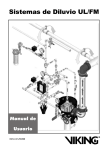
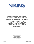
Preaction 353a
August 31, 2006
TECHNICAL DATA
SUREFIRE® SINGLE
INTERLOCKED Pre-primed
PREACTION SYSTEM
1. SYSTEM NAME
SUREFIRE® Single Interlocked Pre-Primed Preaction System
2. MANUFACTURER
THE VIKING CORPORATION
210 N. Industrial Park Road
Hastings, Michigan 49058 U.S.A.
Telephone:
(269)945-9501
(877)384-5464
Fax Number:
(269)945-4495
email: [email protected]
3. SYSTEM DESCRIPTION
(Refer to Figure 1)
The Viking SUREFIRE® Single Interlocked Pre-Primed Preaction System utilizes a Viking Model E or Model F Deluge Valve (A.1),
a Viking Easy Riser® Check Valve (D.2), a PAR-3 Control Panel (F.8), two Electric Release Solenoid Valves (F.2 & F.6), Detectors
(F.9), detector cable(s), Deluge Valve Conventional Trim and Check Valve Trim to form a unique operating system. The system piping
is hydraulically pressurized (See Table 1 for pressure settings) to monitor the integrity of the piping, fittings and sprinklers and to act
as a fail-safe emergency backup to electrical detection system wire and panel malfunctions. The system piping is normally wet and
may NOT be installed in locations subject to freezing. Built in with special features to minimize accidental water damage, unlike wet
systems, the system may be installed where the detector and/or sprinklers are easily damaged or broken accidentally. In addition to
special features that offer fail-safe operation, the Viking SUREFIRE® Single Interlocked Pre-Primed Preaction Systems also provide
excellent fire protection environment with or without electrical power. The system has the capacity for batteries that provide up to ninety
(90) hours of emergency power. If the system is in the set condition and the panel is in trouble condition, or all power fails, the system
will be hydraulically latched by the sprinklers in the system. If the system is operating, no matter the condition of the panel or power,
the system will continue flowing until it is manually shut off.
Preaction systems are commonly used to help minimize accidental water damage and still provide fast water discharge during a
fire emergency. Consult all Authorities Having Jurisdiction prior to installing a SUREFIRE® Single Interlocked Pre-Primed Preaction
System. If using a heat detector, the detector temperature must be lower than the lowest temperature rated sprinkler being used. For
proper location, spacing and positioning of detectors, refer to the Manufacturers recommendations and/or NFPA 72.
NOTE: It is normally not possible to modify the components of the system controls or their interrelation without compromising the listing.
4. TECHNICAL DATA
Listings and Approvals:
UL Listed - Category VLFT
FM Approved - Preaction
Sprinkler Systems
Patent Pending
5. AVAILABILITY
For Technical Data, Installation, Maintenance and Testing Instructions for individual system
components, refer to current Viking Technical Data describing individual Components of the
Preaction System used.
Viking Technical Data may be found on The Viking Corporation’s Web site at
http://www.vikingcorp.com.
The Web site may include a more recent edition of this Technical Data Page.
The Viking Preaction System is available through a network of domestic and international distributors. See the Viking Corp. Web site
for closest distributor or contact The Viking Corporation.
6. GUARANTEES
For details of warranty, refer to Viking’s current list price schedule or contact Viking directly.
7. SYSTEM OPERATION
(Refer to Figure 1)
In the SET condition:
System water supply pressure enters the priming chamber of the Deluge Valve (A.1) through the 1/4” (8 mm) priming line which includes a normally open priming valve (B.1), strainer (B.2), restricted orifice (B.3) and check valve (B.4). In the SET condition, water
supply pressure is trapped in the priming chamber by check valve (B.4) normally closed Emergency Release (B.11) and normally
closed Release Solenoid Valve (F.2). By pre priming the system, the normally open Solenoid Valve (F.6) provides full hydraulic pressure
on the Deluge Valve (A.1). The optional pilot pressure regulating valve (F.7) allows system pressure to be supervised lower than the
system supply pressure. See Table 1 for settings. Water Supply pressure in the priming chamber holds the clapper of the Deluge Valve
(A.1) on the seat due to the differential design of the valve clapper. The clapper separates the inlet chamber from the outlet chamber,
keeping the outlet chamber of the deluge valve dry.
Form No. F_032806
Revised page replaces page 353a-f dated June 29, 2006.
(Revised Trouble and Loss of power prior to operation sections)
Preaction 353b
August 31, 2006
TECHNICAL DATA
SUREFIRE® SINGLE
INTERLOCKED Pre-primed
PREACTION SYSTEM
In Fire conditions:
When the detection system (F.9) operates, the PAR-3 Control Panel (F.8) activates a piezo sounder and energizes normally closed
Release Solenoid Valve (F.2) open. Pressure is released from the priming chamber faster than it is supplied through restricted orifice
(B.3). The Deluge Valve (A.1) clapper opens to allow water to pressurize the system piping and alarm devices. Water enters the
system and Easy Riser® Check Valve (D.2) which continually vents and pressurizes the PORV (B.10) prime chamber. Water will flow
from any open sprinklers or nozzles.
To return the system to “Normal” conditions, drain the system piping and replace any sprinklers that may have operated. Replace any
detectors which have been damaged and place the system in service in accordance with Section 9. Press the “System Reset” button
on the PAR-3 Control Panel (F.8) to clear all alarms.
Panel Trouble, Loss of Power Prior to Operation or Pipe Damage conditions: During Normal Power Supply
Conditions, faults or complete loss of power.
During normal power conditions if the system piping and/or the sprinklers are damaged, the low pressure supervisory switch (E.1)
will activate a supervisory alarm at the Par-3 Release Control Panel (F.8) and the normally open solenoid valve (F.6) will be powered
closed to prevent the deluge valve from opening. This action limits any water flow from the damaged pipe and/or sprinklers to the
volume of water in the pre-primed pipe network.
In the event of a fire during a fault on the detection wiring, loss of primary AC power which has caused a trouble condition or complete
loss of all power, the deluge valve will open allowing water flow if the following conditions occur:
1. The initiating devices (F.9) activate causing the Par-3 Release Control Panel (F.8) to enter an alarm and release condition. The
normally closed solenoid (F.2) will open allowing water pressure to be relieved from the priming chamber of the deluge valve (A.1).
With pressure relieved from the priming chamber, the deluge valve will open and allow water flow. Water will not be discharge into
the protected area until a sprinkler head operates.
2. During a fault condition on the detection wiring or panel which caused a trouble alarm on the Par-3 Release Control Panel (F.8) or
a complete loss of normal AC power and standby battery backup power the normally open solenoid ( F.6) is prevented from operating. During this condition activation of a sprinkler head will allow a hydraulic release of the deluge valve (A.1). Water pressure will
be relieved from the priming chamber, the deluge valve (A.1) will open and allow water to flow.
Loss of Power During Operation:
If all power fails while the system is flowing water, the normally open Release Solenoid (F.6) will open and the normally closed Release
Solenoid (F.2) will close. The PORV (B.10) is already pressurized closed to prevent pressure in the chamber from building up. Water
from main supply will continue entering the system, and through any open sprinkler(s).
Manual Operation:
Any time the handle inside Emergency Release (B.11) is pulled, pressure is released from the priming chamber faster than it can be
replaced through the priming line; the Deluge Valve (A.1) will open. Water will flow to the system piping, activating any connected
alarms, but will not discharge from any closed sprinklers attached to the system until a sprinkler has operated, as in a fire. All alarms
will operate normally. After operating the Emergency Release (B.11), do not close the Emergency Release until the system is ready
to be reset.
8. INSTALLATION
Refer to current Viking Technical Data describing individual components of the Viking SUREFIRE® Single Interlocked Pre-Primed
Preaction System. Technical Data describing the Viking Deluge Valve and other system components are packed with product and in
the Viking Engineering Design Data book.
Also, refer to applicable installation standards, codes, and Authorities Having Jurisdiction.
A.The Deluge Valve (A.1) and Conventional Trim must be installed only in areas where they will not be subjected to freezing temperatures or mechanical damage.
B.All indicating appliances and releasing devices must be compatible and approved for use with the SUREFIRE® Single Interlocked
Pre-Primed Preaction System. Refer to appropriate Fire Protection Equipment Approval Guides and current Viking Technical Data
describing individual components of the Viking SUREFIRE® System.
C.Use Normally Open Heat Detectors (F.9) or Smoke Detectors and Viking Cable as listed for the protection.
9. PLACING THE SYSTEM IN SERVICE AT INITIAL START-UP
(Refer to Figure 1)
Note: Refer to PAR-3 Owner’s Manual, and instructions provided in Technical Data describing the
Viking Deluge Valve and other system components.
To Place the System in Service:
A.Verify that the PAR-3 Control Panel (F.8), Detector Circuits and Detectors have been properly installed and energized according to
instructions provided in Viking Technical Data and the PAR-3 Owner’s Manual.
Preaction 353c
August 31, 2006
TECHNICAL DATA
SUREFIRE® SINGLE
INTERLOCKED Pre-primed
PREACTION SYSTEM
B.Verify that the system has been properly drained. (When plunger is depressed on drip check, (B.7) no water should flow.) System
Drain (G.4) should be closed. Verify that Emergency Release (B.11) is closed.
C.Verify that the System Main Water Supply Control Valve (D.1) is closed and the Deluge Valve (A.1) is trimmed according to current
Viking Trim Technical data page for the system used (See section 12).
D.Verify that the system water supply piping is pressurized up to the closed System Main Water Supply Control Valve (D.1) and the
priming line is pressurized up to the closed Priming Valve (B.1).
E.Restore system water pressure by opening the Bypass Isolation Valve (G.3). Make sure supervisory switch (E.1) is set to proper
activation pressure per Table 1.
F. Open Priming Valve (B.1) and system Maintenance Valve (F.3). When the system is full of water, close the system Bypass Isolation
Valve (G.3).
G.Reset the PAR-3 Control Panel (F.8): Open panel and press “RESET”. Release Solenoid Valve (F.2) should close. Flow from
Release Solenoid Valve (F.2) to Drain Cup (B.14) should stop.
H.Open Flow Test Valve (B.15).
I. Partially open Main Water Supply Control Valve (D.1) (If closed).
J. When full flow develops from Flow Test Valve (B.15), close the Flow Test Valve.Verify that there is no flow from open Auxiliary Drain
(B.6).
K.Close Auxiliary Drain (B.6) and Bypass Valve (G.3).
L. Fully open and secure the Main Water Supply Control Valve. (D.1)
M.Verify that the Alarm Shut-off Valve (B.9) is open and that all other valves are in their normal operating position.
N.Depress the plunger of Drip check (B.7). No water should flow from the Drip Check when the plunger is pushed.
10. EMERGENCY INSTRUCTIONS
(Refer to Figure 1)
Taking System Out of Service:
WARNING: Placing a control valve or detection system out of service may eliminate the Fire
Protection capabilities of the system. Prior to proceeding, notify all Authorities Having Jurisdiction.
Consideration should be given to employment of a Fire Patrol in the affected areas.
After a fire, verify that the fire is OUT and that placing the system out of service has been authorized by the appropriate Authority
Having Jurisdiction.
Sprinkler systems that have been subjected to a fire must be returned to service as soon as possible. The entire system must be
inspected for damage and repaired or replaced as necessary.
A.If All System Components Are Operational:
1. Open Auxiliary Drain (B.6).
2. Silence alarms (optional).
a: To silence electric alarms controlled by PAR-3 Control Panel (F.8), open panel and press “ALARM SILENCE”
b: To silence electric alarms not controlled by PAR-3 Control Panel (F.8), close Alarm Shut-Off Valve (B.9).
3. To return to service immediately, (when no maintenance or repairs are required) :
a: Close Auxiliary Drain (B.6) if opened in step 1-A. If necessary, open System Drain (G.4) to drain system and/or Test Valve
(B.15) to drain the inlet chamber of the Deluge Valve (A.1).
Note: This system is Pre-Primed with water. Draining the system is only required if repairs are required, or if the water in the system is replaced with another supervisory liquid suppressant.
b: Restore system water pressure by opening the Water Supply Valve (F.3). After the system fills with water, Close the Bypass
Isotation Valve (G.3).
c: Open PAR-3 Control Panel (F.8) and press “RESET”.
d: Open Alarm Shut-Off Valve (B.9) (If it was closed in step B-2 above).
e: Verify that all valves are secured in their normal operating position. (Refer to Figure 1)
B.If it is necessary to remove the SUREFIRE® Single Interlocked Pre-Primed Preaction system from service:
1: Close the Main Water Supply control Valve (D.1).
2: Close Priming Valve (B.1) (optional). If necessary, open System Drain (G.4) to drain system and/or Test Valve (B.15) to drain
the inlet chamber of the Deluge Valve (A.1). Close the Maintenance Valve (F.3). If draining the system is necessary, open the
system main drain valve (G.4).
3: Disconnect all power sources to the PAR-3 Control Panel prior to performing any maintenance or repairs to the detection system
(F.9), the panel (F.8), solenoid valves (F.2, F.6), or any electrical component of the system.
C.Perform all maintenance procedures recommended in PAR-3 Owner’s Manual and Technical Data Pages for the individual components of the system that has operated.
1. Replace any piping, detectors (F.9), or sections of detection cable that have been damaged.
Preaction 353d
August 31, 2006
SUREFIRE® SINGLE
INTERLOCKED Pre-primed
PREACTION SYSTEM
TECHNICAL DATA
Note: The complete system operation must be tested after servicing, changing programming, addition or deletion of system components or after any modification, repair, or adjustment to system
hardware or wiring. All components, circuits, system operation or software functions known to
be affected by a change must be 100% tested.
2. Replace any sprinklers and/or spray nozzles that have been damaged or exposed to fire conditions.
D.Restore AC power to PAR-3 Control Panel (F.8). Ensure that standby batteries are charged or charging. Always connect and turn
on AC power source prior to connecting the standby batteries. Connecting the standby batteries to the PAR-3 Control Panel (F.8)
before the AC power is connected and turned on may damage the panel.
E.Return the system to service. Refer to Section E: “PLACING THE SYSTEM IN SERVICE”.
11. INSPECTIONS and TESTS
It is imperative that the system be inspected and tested on a regular basis in accordance with NFPA 25.
Refer to INSPECTIONS and TESTS recommended in current Viking Technical Data describing individual components of the
SUREFIRE® Single Interlocked Pre-Primed Preaction System.
Where difficulty in performance is experienced, contact Viking Technical Service if any field adjustments are to be made.
The frequency of the inspections may vary due to contaminated or corrosive water supplies or corrosive atmospheres. For minimum
maintenance and inspection requirements, refer to NFPA 25. In addition, the Authority Having Jurisdiction may have additional maintenance, testing, and inspection requirements which must be followed.
WARNING: Any system maintenance which involves placing a control valve or detection system out
of service may eliminate the fire protection capabilities of that system. Prior to proceeding, notify
all Authorities Having Jurisdiction. Consideration should be given to employment of a fire patrol in
the affected areas.
NOTICE: The owner is responsible for maintaining the fire protection system and devices in proper
operating condition.
Refer to MAINTENANCE INSTRUCTION provided in the current Viking Technical Data describing individual components of the Viking
Single Interlocked SUREFIRE® Single Interlocked Pre-Primed Preaction used.
Where difficulty in performance is experienced, the valve manufacturer or his authorized representative shall be contacted if any field
adjustment is to be made.
WATER SUPERVISORY SWITCH SETTINGS
Water Supply Detection Circuit Detection Circuit System Water
PSI
Two (DC2) PSI Four (DC4) PSI
Normal PSI*
0 - 250
.75 X Water Supply
10 + DC2
N/A
0 - 250 *
15 + Pm
10 + DC2
25 + DC2
See system wiring diagram #13730
*For use when using lower supervisory pressure than the system
supply and the optional Pilot Pressure Regulating Valve
Pm = Maximum Head Pressure = H x 0.433
where H = height from switch (E.1) to highest sprinkler pipe point at celing
Table 1
Preaction 353e
August 31, 2006
TECHNICAL DATA
SUREFIRE® SINGLE
INTERLOCKED Pre-primed
PREACTION SYSTEM
12. Ordering instructions
To order a complete SUREFIRE® Single Interlocked Pre-Primed Preaction System, the following components must be ordered:
Deluge Valve, Easy Riser® Check Valve, Base Conventional Trim, Check Valve Trim, Release Trim and Tranzorb Kit.
Deluge Valve Part Numbers
DESCRIPTION
DELUGE VALVE
NOMINAL
PART
SIZE
NUMBER
Angle Style
Threaded NPT
Painted Red
Model & Pipe O.D.
Model E-3 48mm 1½" / DN40
09889
Model E-1 60mm 2" / DN50
05852C
HALAR®
Model E-4 48mm 1½" / DN40 09890Q/B
Model E-2 60mm 2" / DN50 08361Q/B
Flange/Flange Painted Red
Flange Drilling Model E-1
ANSI
3"
05912C
ANSI
4"
05909C
ANSI
6"
05906C
ANSI/Japan
6"
07136
PN10/16 DN80
08626
PN10/16 DN100
08629
PN10/16 DN150
08631
HALAR®
Flange Drilling Model E-2
ANSI
3"
08362Q/B
ANSI
4"
08363Q/B
ANSI
6"
08364Q/B
PN10/16 DN80
08862Q/B
PN10/16 DN100
08863Q/B
PN10/16 DN150
08864Q/B
Flange/Groove Painted Red
Flange Drilling / Pipe O.D. Model E-1
ANSI / 89mm
3"
05835C
ANSI / 114mm
4"
05839C
ANSI / 168mm
6"
05456C
PN10/16 / 89mm DN80
09539
PN10/16 / 114mm DN100
09540
PN10/16 / 168mm DN150
05456C
HALAR®
Flange Drilling / Pipe O.D. Model E-2
ANSI / 89mm
3"
11064Q/B
ANSI / 114mm
4"
11065Q/B
ANSI / 168mm
6"
11001Q/B
PN10/16 / 168mm DN150
11001Q/B
DESCRIPTION
Straight Through
Flange/Groove Painted Red
Flange Drilling / Pipe O.D.
ANSI / 89mm
ANSI / 114mm
ANSI / 168mm
PN10/16 / 89mm
PN10/16 / 114mm
PN10/16 / 165mm
PN10/16 / 168mm
HALAR®
Flange Drilling / Pipe O.D.
ANSI / 89mm
ANSI / 114mm
ANSI / 168mm
PN10/16 / 89mm
PN10/16 / 114mm
PN10/16 / 165mm
PN10/16 / 168mm
Groove/Groove Painted Red
Pipe O.D.
48mm
60mm
73mm
76mm
89mm
114mm
165mm
168mm
219mm
HALAR®
Pipe O.D.
48mm
60mm
73mm
76mm
89mm
114mm
165mm
168mm
219mm
NOMINAL
SIZE
PART
NUMBER
Model F-1
3"
4"
6"
DN80
DN100
DN150
DN150
12018
11952
11954
12030
11958
12640
11954
DESCRIPTION
Straight Through
Threaded
Painted Red
Pipe O.D. Model F-1
NPT 48mm
1½"
NPT 60mm
2"
NPT 65mm
2½"
BSP 48mm
DN40
BSP 60mm
DN50
HALAR® Model F-2
NPT 65mm
2½"
Flange/Flange
Model F-2
3"
4"
6"
DN80
DN100
DN150
DN150
12019Q/B
11959Q/B
11961Q/B
12644Q/B
12645Q/B
12641Q/B
11961Q/B
Model F-1
1½" / DN40
2" / DN50
2½" / DN65
DN80
3" / DN80
4" / DN100
DN150
6" / DN150
8" / DN200
12125
12057
12403
12729
12022
11513
11910
11524
11018
Model F-2
1½" / DN40
2" / DN50
2½" / DN65
DN80
3" / DN80
4" / DN100
DN150
6" / DN150
8" / DN200
12127Q/B
12058Q/B
12404Q/B
12730Q/B
12023Q/B
11514Q/B
11911Q/B
11525Q/B
11118Q/B
NOMINAL
SIZE
Painted Red
Flange Drilling Model F-1
ANSI
3"
ANSI
4"
ANSI
6"
ANSI
8"
ANSI/Japan
6"
PN10/16
DN80
PN10/16 DN100
PN10/16 DN150
PN10 DN200
PN16 DN200
PART
NUMBER
12126
12059
12401
12682
12686
12402Q/B
12014
11953
11955
11991
11964
12026
11965
11956
11995
11999
HALAR®
Flange Drilling Model F-2
ANSI
3"
ANSI
4"
ANSI
6"
ANSI
8"
PN10/16
DN80
PN10/16 DN100
PN10/16 DN150
PN10 DN200
PN16 DN200
12015Q/B
11960Q/B
11962Q/B
11992Q/B
12027Q/B
11966Q/B
11963Q/B
11996Q/B
12000Q/B
Check Valve Part Numbers
DESCRIPTION
IN-LINE CHECK VALVE
Groove / Groove
Note: When viewing this datapage
online, Part Numbers displayed in
BLUE are hyperlinks. Clicking the
part number will open the corresponding Technical Data Page.
EASY RISER ® ������
SWING
CHECK VALVE
Flange/Flange
Flange Drilling
ANSI
ANSI
ANSI
ANSI/Japan
ANSI/Japan
ANSI/Japan
PN10/16
PN10/16
PN10/16
PN10
PN16
NOMINAL
SIZE
Model L-1
1-1/2” / DN40
2” / DN50
PART
NUMBER
11054
11059
Rated to 250 psi (1 724 kPa)
Model F-1
3"
4"
6"
DN100
DN150
DN200
DN80
DN100
DN150
DN200
DN200
08505
08508
08511
09039
09385
14023
08796
08797
08835
08836
12355
DESCRIPTION
NOMINAL
SIZE
PART
NUMBER
Model F-1
3"
4"
6"
8"
DN80
DN100
DN150
DN150
DN200
DN200
08506
08509
08512
08515
12648
12649
12652
08512
12651
12650
Flange/Groove
Flange Drilling / Pipe O.D.
ANSI / 89mm
ANSI / 114mm
ANSI / 168mm
ANSI / 219mm
PN10/16 / 89mm
PN10/16 / 114mm
PN10/16 / 165mm
PN10/16 / 168mm
PN10 / 219mm
PN16 / 219mm
Groove/Groove
Pipe O.D.
73mm
89mm
114mm
165mm
168mm
219mm
Model E-1
2½" / DN65
Model F-1
3" / DN80
4" / DN100
DN150
6" / DN150
8" / DN200
07929
08507
08510
12356
08513
08516
Preaction 353f
August 31, 2006
TECHNICAL DATA
SUREFIRE® SINGLE
INTERLOCKED Pre-primed
PREACTION SYSTEM
Deluge Valve Trim
Package Part Numbers
DESCRIPTION
CONVENTIONAL
DELUGE VALVE TRIM
Includes Deluge Valve
Accessory Package
Release Trim Package
Part Numbers
NOMINAL
PART
SIZE
NUMBER
Rated to 250 psi (1 724 kPa)
Use with Angle Style Valves
Galvanized
1½" / DN40
10202
2" / DN50
10203
3" / DN80
10204
4" / DN100
10205
6" / DN150
10206
DESCRIPTION
RELEASE TRIM PACKAGES
Use with Pre-Primed Surefire®
Includes:
- Solenoid Valve, N.C., 24VDC
- Solenoid Valve, N.O., 24VDC
- Supervisory Pressure Switch
Brass
Vert.
Vert.
1½" / DN40
10250
2" / DN50
10251
3" / DN80
10252
4" / DN100
10253
6" / DN150
10254
FINISH
Angle Style
Galvanized
1½" / DN40
2" / DN50
3" / DN80
4" / DN100
6" / DN150
PART
NUMBER
Valves
13657-1
13657-1
13658-1
13658-1
13658-1
Brass
Use with Straight Through
Valves
Galvanized
1½" / DN40
12409-1
2" / DN50
12409-1
1½" / DN40
13657-2
2" / DN50
13657-2
3" / DN80
13658-2
4" / DN100
13658-2
6" / DN150
13658-2
Straight Through Valves
Galvanized
1½" / DN40
13659-1
2" / DN50
13659-1
2½" / DN65
12298-1
3" / DN80
13660-1
3" / DN80
12298-1
4" / DN100
13660-1
4" / DN100
11712-1
6" / DN150
13660-1
6" / DN150
11714-1
Brass
8" / DN200
11077
1½" / DN40
13659-2
2" / DN50
13659-2
3" / DN80
13660-2
4" / DN100
13660-2
6" / DN150
13660-2
Brass
1½" / DN40
2" / DN50
12409-2
12409-2
2½" / DN65
12298-2
3" / DN80
12298-2
4" / DN100
11712-2
6" / DN150
11714-2
8" / DN200
11165
Check Valve Trim
Package Part Numbers
DESCRIPTION
NOMINAL
SIZE
PART
NUMBER
1½" / DN40
12960
2" / DN50
12960
Check Valve Trim
Preaction 353g
August 31, 2006
TECHNICAL DATA
SUREFIRE® SINGLE
INTERLOCKED Pre-primed
PREACTION SYSTEM
Figure 1: Surefire® Single-Interlocked Pre-Primed
Preaction System Controlled by Electric Release
Vertical Straight Through Style Valve Conventional Trim
Preaction 353h
August 31, 2006
TECHNICAL DATA
SUREFIRE® SINGLE
INTERLOCKED Pre-primed
PREACTION SYSTEM
Figure 2: Surefire® Single-Interlocked Pre-Primed
Preaction System Controlled by Electric Release
Angle Style Valve Conventional Trim
Preaction 353i
August 31, 2006
TECHNICAL DATA
SUREFIRE® SINGLE
INTERLOCKED Pre-primed
PREACTION SYSTEM
Easy Riser™
Check Valve & Trim
Figure 3: 1-1/2” & 2” (DN40
& DN50) Angle Style Release
Trim Arrangement
Model E Deluge
Valve & Trim (See
pages 353 e & f)
Galvanized
Brass
13657-1
13657-2
See separate trim drawing for base Easy
Trim arrangement.
See Table 2 for ordering complete SUREFIRE™ Assembly.
Preaction 353j
August 31, 2006
TECHNICAL DATA
SUREFIRE® SINGLE
INTERLOCKED Pre-primed
PREACTION SYSTEM
Easy Riser™
Check Valve & Trim
Model E Deluge
Valve & Trim (See
�����
pages 353 e & f)
Figure 4: 1-1/2” & 2” (DN40 &
DN50) Straight Through Vertical
Release Trim Arrangement
Galvanized
Brass
13659-1
13659-2
See separate trim drawing for base Easy
Trim arrangement.
See Table 2 for ordering complete SUREFIRE™ Assembly.
Preaction 353k
August 31, 2006
TECHNICAL DATA
SUREFIRE® SINGLE
INTERLOCKED Pre-primed
PREACTION SYSTEM
Easy Riser™
Check Valve & Trim
Figure 5: 2-1/2”, 3”, 4” 6” & 8” (DN65 &
DN80, DN100, DN150 & DN200)
Straight Through Vertical Release Trim
Arrangement
Model E Deluge
Valve & Trim (See
�����
pages 353 e & f)
Galvanized
Brass
13660-1
13660-2
See separate trim drawing for base Easy Trim
arrangement.
See Table 2 for ordering complete SUREFIRE™ Assembly.
Preaction 353l
August 31, 2006
TECHNICAL DATA
SUREFIRE® SINGLE
INTERLOCKED Pre-primed
PREACTION SYSTEM
Easy Riser™
Check Valve & Trim
Model E Deluge
Valve & Trim (See
�����
pages 353 e & f)
Figure 6: 3”, 4” & 6” (DN80, DN100 &
DN150) Angle Style
Release Trim Arrangement
Galvanized
Brass
13658-1
13658-2
See separate trim drawing for base Easy
Trim arrangement.
See Table 2 for ordering complete SUREFIRE™ Assembly.
Form No. F_032806
Revised page replaces page 353a-f dated June 29, 2006.
(Revised Trouble and Loss of power prior to operation sections)