1
VPN Concentrator 4500/5300
Installation and Configuration Guide
June 2009
800-1190-03, Revision 3
Document and Software Copyrights
Copyright © 2009 by ShoreTel, Inc. Synnyvale, California, U.S.A. All rights reserved. Printed in the United
States of America. Contents of this publication may not be reproduced or transmitted in any form or by any
means, electronic or mechanical, for any purpose, without prior written authorization of ShoreTel, Inc.
ShoreTel Inc. reserves the right to make changes without notice to the specifications and materials contained herein and shall not be responsible for any damage (including consequential)
caused by reliance on the materials presented, including, but not limited to, typographical, arithmetic, or listing errors.
Company Information
ShoreTel 960 Stewart Drive, Sunnyvale, California USA +1.408.331.3300 +1.408.331.3333 (Fax)
Contents
1.1 Specifications ...........................................................................................1
1.1.1 VPN Concentrator 4500............................................................................................ 1
1.1.2 VPN Concentrator 5300............................................................................................ 1
1.2 Hardware Installation................................................................................1
1.2.1 VPN Concentrator 4500............................................................................................ 1
1.2.1.1
Requirements for Installation .................................................................... 1
1.2.1.2
Front Panel LEDs ..................................................................................... 2
1.2.1.3
Back Panel................................................................................................ 3
1.2.1.4
Physical Installation .................................................................................. 4
Required Tools and Materials................................................................................ 4
Desktop Installation ............................................................................................... 4
Wall-Mount Installation .......................................................................................... 5
Rack-Mount Installation ......................................................................................... 5
Connecting the Power and Cables ........................................................................ 6
1.2.1.5
Initial Configuration ................................................................................... 6
1.2.2 VPN Concentrator 5300............................................................................................ 7
1.2.2.1
Requirements for Installation .................................................................... 7
1.2.2.2
Front Panel Overview ............................................................................... 8
1.2.2.3
Back Panel Overview................................................................................ 9
1.2.2.4
Physical Installation ................................................................................ 10
Rack-Mount Installation ....................................................................................... 10
Connecting the Power and Cables ...................................................................... 10
1.2.2.5
Initial Configuration ................................................................................. 11
1.2.3 Deployment Scenarios............................................................................................ 12
2.1
2.2
2.3
2.4
3.1
3.2
3.3
Introduction.............................................................................................13
Redundant VPN Concentrators..............................................................14
SSL VPN Authentication Mechanisms ...................................................14
Other Features .......................................................................................14
Firmware Upgrade..................................................................................15
Licensing ................................................................................................16
Configuration ..........................................................................................17
3.3.1 GUI Interface........................................................................................................... 18
3.3.1.1
Services Configuration............................................................................ 18
3.3.1.2
Set Link................................................................................................... 19
3.3.1.3
Management Interface (VPN Concentrator 5300 Only).......................... 20
3.3.1.4
Route ...................................................................................................... 21
3.3.1.5
VLAN ...................................................................................................... 21
3.3.1.6
SSL VPN Main Page .............................................................................. 23
Global Configuration ............................................................................................ 24
LDAP Configuration ............................................................................................. 25
Proxy ARP Configuration..................................................................................... 26
Stunnel IP Pool .................................................................................................... 26
3.3.1.7
SSL VPN Databases .............................................................................. 27
Username and Password Database .................................................................... 27
MAC Address Whitelist ........................................................................................ 28
MAC Address Blacklist ........................................................................................ 29
Current Sessions ................................................................................................. 30
3.3.2 Configuring VPN Parameters on IP Phones ........................................................... 31
3.3.2.1
Configuration via config files................................................................... 31
i
Contents
3.3.2.2
3.3.2.3
Manual configuration .............................................................................. 32
Summary of recommended configuration and deployment procedure: .. 33
4.1 Tools and Troubleshooting.....................................................................35
4.1.1 Network Information................................................................................................ 36
4.1.2 Network Connectivity .............................................................................................. 37
4.1.3 Viewing Log Files.................................................................................................... 38
4.1.4 Packet Capture ....................................................................................................... 39
4.1.4.1
Capturing Packets for an Individual SSL Connection ............................. 39
ii
Chapter 1:
Specifications
C
1.1
Specifications
1.1.1
VPN Concentrator 4500
1.1.2
H
A
P
T
E
R
WAN Ports
1 x 10/100 Ethernet
LAN Ports
4 x 10/100 Ethernet
Serial Ports
1 x RS-232
Dimensions
Height 1.688“ (42.863 mm), Width 10.438 “ (265.113 mm), Depth 6.625 “
(168.275 mm)
Weight
2 lb (0.91 kg)
Power
12V @ 3A, external AC Adapter
Environmental
Operating Temperature: 5° to 40°C
Humidity: 20% to 80%, non-condensing
1
VPN Concentrator 5300
WAN Ports
1 x 10/100 Ethernet
LAN Ports
1 x 10/100 Ethernet
Management Ports
1 x 10/100 Ethernet
Serial Ports
1 x RS-232
Dimensions
19” Rack Mount, 1RU
Weight
11.5 lb (5.28 kg)
Power
100/240v VAC, auto-selecting, 47 to 63 Hz
Environmental
Operating Temperature: 5° to 40°C
Humidity: 5% to 90%, non-condensing
1.2
Hardware Installation
1.2.1
VPN Concentrator 4500
1.2.1.1
Requirements for Installation
• A computer with a web browser as supported by ShoreTel (Microsoft Internet
•
Explorer).
Two Ethernet cables
VPN Concentrator Installation and Configuration Guide
1
Hardware Installation
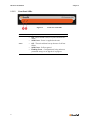
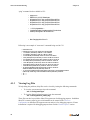
1.2.1.2
Chapter 1:
Front Panel LEDs
Figure 1-1
Item
Description
PWR
•
•
Status
•
•
•
2
Front view of the 4500
Off – Power switch is off (or no power from the AC
outlet)
Solid Green – Power is supplied to the unit
Off – The unit could not boot up because of self test
failure
Solid Green – Self test passed.
Flashing Green – Configuration is being written to
permanent storage or an upgrade is in progress
Chapter 1:
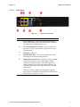
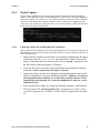
1.2.1.3
Hardware Installation
Back Panel
Figure 1-2
Call out
Back view of the 4500
Description
A
Power Connector – Accepts the plug from the supplied
power adapter which can be connected to an AC outlet on
the wall using the supplied power cord.
B
4 Ports 10/100 Mbps LAN Switch – Any one of the four
ports can be used to connect to the Local Area Network
(LAN) network.
C
USB Ports – Not used.
D
Ethernet WAN Port – This port is typically used when
connecting the 4500 to an upstream router.
E
Management Console Port – This port is used to establish
a local console session with the 4500 using a VT100
terminal or emulation program. The cable required is a
straight-through 8-wire cable with female connector. The
serial port uses a baud rate of 9600, 8 data bits, 1 stop bit
and no parity.
This port is used for debug or local diagnostic purposes
only. Primary configuration of the 4500 is performed from a
web browser as covered in Chapter 3.
VPN Concentrator Installation and Configuration Guide
3
Hardware Installation
Call out
F
Chapter 1:
Description
Erase –
•
If pressed twice in quick succession,
the CLI password will be changed to
its original password.
•
If pressed three times in quick
succession, the 5300 will revert to
factory default settings. All passwords
will be reset and all prior
configurations will be erased.
Note: The default LAN address will be
set to 192.168.1.1
Caution: Setting the system
configuration to factory default will
erase all configuration changes.
G
Link Speed LED
Off – If the link is up, it indicates that the port is connected
to a 10BaseT Ethernet switch or hub.
Solid Amber – Indicates that the port is connected to a
100BaseT Ethernet switch or hub.
H
Link Status LED
Solid Green – Ethernet link is up.
Blinking Green – Indicates activity on the link.
1.2.1.4
Physical Installation
The 4500 device is designed for desktop, rack or wall-mount installation. Observe the
following guidelines when installing the system:
•
•
Always verify that the AC cord is disconnected from a power source prior to
installation.
Ensure that the installation site has adequate air circulation and meets the minimum
operating conditions for the system as specified in Specifications of this document
Required Tools and Materials
•
4
If the unit will be mounted on the wall:
— 1 Flat or Philips screw driver
— 2 round or flat head Philips or slotted screws – 1 ½ inch long
Chapter 1:
Hardware Installation
— 2 hollow wall anchors
•
If the unit will be mounted in a shelf
— 1 Flat or Philips screw driver
•
Ethernet cables to connect the LAN ports to LAN switches or other Ethernet devices
and the WAN port to a firewall or an upstream router.
Desktop Installation
1. Remove the 4500 and the accessories from the shipping container.
2. Place the 4500 on a flat, dry surface such as a desktop, shelf or tray.
Wall-Mount Installation
You can mount the 4500 on a wall using the two mounting brackets on the bottom of the
appliance. We recommend that you use the two round or pan head screws.
1. Install two screws 5.9063” (150 mm) horizontally apart on a wall or other vertical
surface. The screws should protrude from the wall so that you can fit the appliance
between the head of the screw and the wall. If you install the screws in drywall, use
hollow wall anchors to ensure that the unit does not pull away from the wall due to
prolonged strain from the cable and power connectors.
2. Remove the 4500 and accessories from the shipping container.
3. Mount the 4500 on the wall as shown below.
VPN Concentrator Installation and Configuration Guide
5
Hardware Installation
Chapter 1:
4. Do not mount the 4500 on the wall as shown below.
Rack-Mount Installation
You can mount the 4500 in a 19” rack by using the rack-mount kit supplied with the product.
1. Attach the ear mounts to both sides of the 4500 with the screws.
2. Attach the 4500 with the ear mounts to the shelf by screwing the ear mounts to the shelf
with screws.
Connecting the Power and Cables
1. Connect one end of an Ethernet cable to local LAN port 4 of the 4500. This port can be
seen in the area “B” of Figure 1-2. Connect the other end of the cable to your
computer’s Ethernet port.
2. Connect one end of an Ethernet cable to the WAN port of the 4500, shown in Figure 12 as “D,” and the other end to Ethernet port of an appropriate device based on your
deployment scenario. Please see section 1.2.3 for examples of deployment scenarios.
3. Plug one end of the power adapter into an AC outlet and the other end into the power
receptacle on the 4500. Make sure that the power and status LEDs, shown in Figure 11 as “A” and “B”, are solid green after a short while.
WARNING
Always connect the AC power cord to an AC outlet suitable for the power
supply that came with the unit in order to reduce the risk of damage to it.
• Connect one end of the AC power cord to the power adapter and the
other one to the AC outlet.
• Connect plug from the power adapter to the Power Connector on the
4500. Sometimes a little force is necessary to get the plug properly
positioned.
CAUTION
Secure the power adapter using a fastener or tie wrap to nearby shelf so that it
does not hang from the power connector.
• If connecting to a WAN router, cable modem or DSL modem, then
connect the Ethernet cable to the Ethernet WAN port on the 4500 and
the other end to the WAN device.
1.2.1.5
Initial Configuration
You can configure the 4500 using a web browser such as Internet Explorer or Netscape
Navigator. The 4500 is shipped with the pre-configured IP address 192.168.1.1 for the LAN
ports.
6
Chapter 1:
Hardware Installation
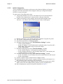
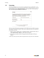
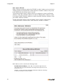
To connect to the 4500, follow these steps:
1. Assign static IP address 192.168.1.2 with subnet 255.255.255.0 to the Ethernet
interface of the computer that is connected to the LAN port of the 4500
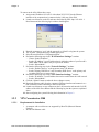
2. Launch a web browser on the PC and enter the following URL: http://192.168.1.1.
Press Return and the following login window should appear:
3.
4.
5.
6.
7.
8.
9.
10.
11.
12.
Enter the username as “root” and the password as “default” to log into the system.
The “System” configuration page should appear now.
Select Network from the “Configuration Menu”.
Perform the following steps in the “WAN Interface Settings:” section:
— Choose “Static IP Address”
— Set the “IP Address:” to an IP address that is within the subnet of your firewall’s
DMZ. Note: The IP address may be a private IP address.
— Set the “Subnet Mask:”
Perform the following steps in the “Network Settings:” section:
— Set the “Default Gateway” to the upstream router’s IP address.
— Set the "Primary DNS Server" and "Secondary DNS Server" to the primary and
secondary DNS servers respectively.
Perform the following steps in the “LAN Interface Settings:” section:
— Set the “IP Address:” to an IP address that can be reached from the LAN network.
— Set the “Subnet Mask:”
Click the “Submit” button to make the above changes current.
Detach the Ethernet cable from the computer’s Ethernet interface and connect it to a
hub or Ethernet switch connecting to the LAN network.
Launch a web browser on any computer on the LAN networks and enter the LAN IP
address of the 4500. Press Return and the following log into the system as explained
above.
Start configuring the system following the information in Chapter 3.
1.2.2
VPN Concentrator 5300
1.2.2.1
Requirements for Installation
• A computer with a web browser as supported by ShoreTel (Microsoft Internet
•
Explorer).
At least one Ethernet cable
VPN Concentrator Installation and Configuration Guide
7
Hardware Installation
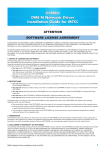
1.2.2.2
Chapter 1:
Front Panel Overview
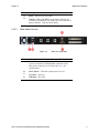
Figure 1-3
Call out
A
Front view of the 5300
Description
Erase –
•
If pressed twice in quick succession,
the CLI password will be changed to
its original password.
•
If pressed three times in quick
succession, the 5300 will revert to
factory default settings. All passwords
will be reset and all prior
configurations will be erased.
Note: The default LAN address will be
set to 192.168.1.1
Caution: Setting the system
configuration to factory default will
erase all configuration changes.
B
Power LED
•
•
C
Disk Activity LED
•
•
•
8
Off – Power switch is off (or no power from the AC
outlet)
Solid Green – Power is supplied to the unit
Off – No disk activity
Flashing Red – Data is being read or written to the
disk.
Solid Red – System failure.
D
Port 3 (Management Port) – Out of band management
port used for configuration purposes. DHCP client is
enabled on this port from the factory.
E
Port 2 (WAN Port) – Connects to the WAN or upstream
router. DHCP enabled from the factory.
F
Port 1 (LAN Port) – Connects to the local network or
LAN. Factory configured for static IP with 192.168.1.1 IP
address.
Chapter 1:
Hardware Installation
Call out
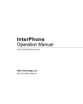
1.2.2.3
Description
G
Reset – Hard reset of the system.
H
Console – DB9 serial (RS232) port (male connector) for
CLI based configuration. The serial port uses a baud rate of
9600, 8 data bits, 1 stop bit and no parity.
Back Panel Overview
Figure 1-4
Call out
Back view of the 5300
Description
A
Power Inlet – Accepts a 3-pin Shroud Female connector of
a power cord with 3-pin Shroud Male connector on the
other end to connect to an AC outlet (See Power for
specifications).
B
Power Switch – Turns the system power on or off
C
VGA Port – Not used.
D
USB Ports – Not used.
VPN Concentrator Installation and Configuration Guide
9
Hardware Installation
1.2.2.4
Chapter 1:
Physical Installation
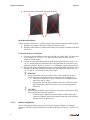
Rack-Mount Installation
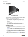
Figure 1-5 Ear mounts on the 5300
The 5300 is designed for 19” rack mount installation. Simply secure the ear mounts (as shown
in Figure 1-5) on both sides of the chassis to the rack post with screws.
Please observe the following guidelines when installing the system:
•
•
•
•
Never assume that the AC cord is disconnected from a power source. Always check
first.
Never place objects greater than 5 lbs on top of the appliance as damage to the chassis
may result.
Always connect the AC power cord to a properly grounded AC outlet to avoid damage
to the system or injury.
Ensure that the physical location of the installation has adequate air circulation and
meets the minimum operating conditions as provided in the environmental
specifications for the system.
Connecting the Power and Cables
1. Connect one end of an Ethernet cable to local LAN port (Port 1) of the 5300. This port
can be seen as “F” in Figure 1-3. Connect the other end of the cable to your computer’s
Ethernet port.
2. Connect one end of an Ethernet cable to the WAN port (Port 2) of the 5300, shown in
Figure 1-3 as “E,” and the other end to Ethernet port of an appropriate device based on
your deployment scenario. Please see section 1.2.3 for examples of deployment
scenarios.
3. Connect the 3-pin Shroud Female connector of the power cord to the AC socket on the
5300 shown as “A” in Figure 1-4. Connect the other end of the power cord into an AC
outlet on the wall.
4. Turn on the power by pressing 1 on the power switch (shown as “B” in Figure 1-4).
5. Make sure that the power LED (shown as “B” in Figure 1-3) is solid green and the disk
activity LED (shown as “C” in Figure 1-3) in not solid red.
10
Chapter 1:
1.2.2.5
Hardware Installation
Initial Configuration
You can configure the 5300 using a web browser such as Internet Explorer or Netscape
Navigator. The VPN Concentrator 5300 is shipped with the pre-configured IP address
192.168.1.1 for the LAN ports.
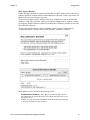
To connect to the 5300, follow these steps:
1. Assign static IP address 192.168.1.2 with subnet 255.255.255.0 to the Ethernet
interface of the computer that is connected to the LAN port of the 5300
2. Launch a web browser on the computer and enter the following URL: http://
192.168.1.1. Press Return and the following login window should appear:
3.
4.
5.
6.
7.
8.
9.
10.
11.
12.
Enter the username as “root” and the password as “default” to log into the system.
The “System” configuration page should appear now.
Select Network from the “Configuration Menu”.
Perform the following steps in the “WAN Interface Settings:” section:
— Choose “Static IP Address”
— Set the “IP Address:” to an IP address that is within the subnet of your firewall’s
DMZ. Note: The IP address may be a private IP address.
— Set the “Subnet Mask:”
Perform the following steps in the “Network Settings:” section:
— Set the “Default Gateway” to the upstream router’s IP address.
— Set the "Primary DNS Server" and "Secondary DNS Server" to the primary and
secondary DNS servers respectively.
Perform the following steps in the “LAN Interface Settings:” section:
— Set the “IP Address:” to an IP address that can be reached from the LAN network.
— Set the “Subnet Mask:”
Click the “Submit” button to make the above changes current.
Detach the Ethernet cable from the computer’s Ethernet interface and connect it to a
hub or Ethernet switch connecting to the LAN network.
Launch a web browser on any computer on the LAN network and enter the LAN IP
address of the 5300. Press Return and log into the system as explained above.
Start configuring the system following the information in Chapter 3.
VPN Concentrator Installation and Configuration Guide
11
Hardware Installation
1.2.3
Chapter 1:
Deployment Scenarios
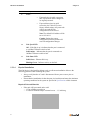
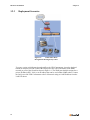
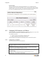
Figure 1-6
Connected to WAN
through firewall and gateway router
To secure, restrict or inhibit pass-through traffic to the VPN Concentrator, it must be deployed
behind an enterprise firewall. Connect the WAN port of the VPN Concentrator to the DMZ
network (or port) of the firewall as shown in Figure 1-6. The WAN port should be assigned to a
private IP address (RFC 1918), or an IP address that can be used within a DMZ subnet. Connect
the LAN port of the VPN Concentrator to the LAN network using an LAN IP address from the
LAN’s IP subnet.
12
Chapter 2:
Introduction
C
2.1
H
A
P
T
E
R
2
Introduction
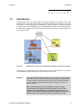
The SSL based VPN Concentrator enables many remote VoIP Phones to establish secure voice
communications with a ShoreTel telephone system through SSL VPN tunnels. For every SSL
VPN tunnel, a virtual PPP interface is created on the VPN Concentrator. A PPP peer interface
is created at the remote VoIP Phone. The VOIP signaling and media streams passing through
the PPP interface within the SSL VPN tunnel are therefore completely secure through the use
of encryption in SSL.
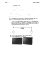
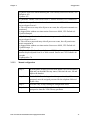
Figure 2-1
Remote phones connectivity to Headquarters through secure SSL VPN tunnels
A maximum of 10 simultaneous SSL VPN tunnels can be licensed on the 4500. A maximum
of 100 simultaneous SSL VPN tunnels can be licensed on the 5300.
WARNING:
If ShoreTel VPN phones will be deployed in remote locations, 911 calls placed from
these phones will be routed to the Public Safety Answering Point (PSAP) nearest
the site that hosts the switch and VPN concentrator. If the remote ShoreTel VPN
phone is outside of the PSAP’s designated area, this will delay or prevent an
effective response.
When remotely deploying a ShoreTel VPN phone, Shoretel strongly
recommends that you implement a 3rd-party solution which can route
emergency calls to the PSAP that is nearest to the VPN phone. If such a
solution is not available, the remote ShoreTel VPN phone should be clearly
labeled so that its users know these restrictions regarding 911 usage.
Contact Center Administrator Manual
13
Redundant VPN Concentrators
2.2
Chapter 2:
Redundant VPN Concentrators
You can deploy multiple VPN concentrators for the purposes of redundancy and/or load
balancing.
Note: Separately apply each license to enable VPN tunnels. Licenses cannot be reused.
Please refer to section 3.3.2.1 for details on making the remote IP phones aware of multiple
VPN concentrators.
2.3
SSL VPN Authentication Mechanisms
The following authentication modes are supported on the VPN Concentrator:
•
User name and password validation – The SSL VPN client on the remote phone is
expected to provide the username and password so that they can be matched against
the following databases:
— Local database (default) – A list of valid usernames and their associated
passwords configured for the authentication in the local database by the
administrators.
— LDAP server database (optional) – This option requires an external LDAP server,
such as Microsoft Active Directory, containing the username and password
information for authentication. LDAP needs to be enabled in the VPN
Concentrator before this database can be used instead of the local database.
2.4
•
MAC Address White list Validation (optional) – When enabled, a local database of
MAC addresses is used to validate the MAC address of a remote phone. The database
can be populated by the administrators using the GUI. If the MAC address of a remote
phone is not found in this database, then the SSL VPN connection request is rejected.
•
MAC Address Blacklist Rejection (optional) – When enabled, a local database of
MAC addresses is used to identify the remote phones that should be denied access to
the network. The database can be populated by the administrators using the GUI. If
the MAC address of a remote phone is found in this database, then the SSL VPN
connection request is rejected.
Other Features
Understanding of the following features will be helpful in configuring the device:
14
•
IP Address Assignment – A valid pool of IP address from the corporate LAN's
internal (private) IP subnet will be used by the VPN Concentrator to assign IP
addresses to the VPN phones via the virtual PPP connections over the SSL VPN. An
IP address pool has to be preconfigured on the VPN Concentrator by the administrator
so that a valid IP address can be assigned to each VoIP phone connected to the VPN
Concentrator.
•
Session Timeout – An optional global timeout value for SSL VPN sessions can be
configure by the administrator. Any SSL VPN session will be terminated if it has been
active for the duration of the timeout value.
•
Active Sessions – The system maintains a runtime list of all current active SSL VPN
sessions. The administrator can delete one or more active SSL VPN sessions if
necessary.
Chapter 2:
Other Features
•
History Log – A history log of all connection requests is maintained which includes
information such as success and failure of sessions establishment, etc.
Contact Center Administrator Manual
15
Other Features
16
Chapter 2:
Chapter 3:
Firmware Upgrade
C H A P T E R
3.1
3
Firmware Upgrade
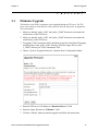
The firmware on the VPN Concentrator can be upgraded through an FTP server. The FTP
server can be sitting on either WAN or LAN network. Follow the steps below to upgrade the
VPN Concentrator:
1. Make sure that the “pub/e_4500” and “pub/e_5300lf” directories exist under the
root directory of the FTP server.
2. Make sure that the “pub/e_4500” and “pub/e_5300lf” directories exist under the
root directory of the FTP server.
3. To upgrade VPN Concentrator 4500, obtain the image files from ShoreTel support
and place them in the “pub/e_4500” directory. Place the image files in “pub/
e_5300lf” directory for VPN Concentrator 5300.
4. Choose “System→Upgrade Firmware” submenu from “Configuration Menu”
5. Enter the FTP server’s IP address in “Download Server:” field.
6. Enter the image file name in “Filename:” field.
7. Click the “Submit” button to start the upgrade and follow the instructions.
VPN Concentrator Installation and Configuration Guide
15
Licensing
3.2
Chapter 3:
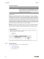
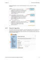
Licensing
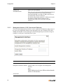
The VPN Concentrator may or may not have preconfigured licenses for SSL VPNs. To view
the preconfigured licenses, choose “System” submenu from “Configuration Menu” on the left
of the web page. Under the “Registration Status:” section, choose the “View license key”
link. The following page should then be displayed.
VPN Concentrator 4500 supports a maximum of 10 SSL VPN sessions and VPN Concentrator
5300 supports a maximum of 100 SSL VPN sessions. Additional licenses can be obtained by
following the steps below.
1. Choose “System” submenu from “Configuration Menu” and provide the value of
“LAN Interface MAC Address:” field to ShoreTel support.
2. Specify the part number to ShoreTel support based on the number of licenses
required.
A license key will be provided by ShoreTel support after the receipt of the above information.
16
Chapter 3:
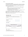
Configuration
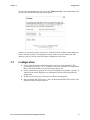
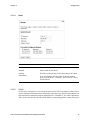
To enter a newly obtained license key, choose the “Edit License Key” link at the bottom of the
License page, and the following page should appear:
Enter the new license key in the “License Key” field and click the “Submit” button. Make sure
that the “Stunnel Sessions” field displays the correct number of licenses afterwards. Note
down this value as it will be needed in further configuration of the device.
3.3
Configuration
1. If the LAN network has sub networks that need to be accessed through the VPN
Concentrator, then choose “Route” submenu of “System” submenu of “Configuration
Menu. Add the information for each sub network one by one.
2. Set the system name by going to the “Services Configuration” page under “System”. In
addition set the remote logging server information if help is needed from ShoreTel
support team.
3. Set link speeds if necessary, otherwise leave them to Autonegotiate.
4. Start configuring SSL VPN services. Also, use the maximum SSL VPN sessions value
obtained in step 1 during this process.
VPN Concentrator Installation and Configuration Guide
17
Configuration
3.3.1
GUI Interface
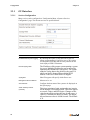
3.3.1.1
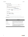
Services Configuration
Chapter 3:
Many services can be configured on “Configuration Menu→System→Services
Configuration” page. The relevant services are specified below.
Parameter
18
Description
Enable Remote System Logging
By checking this option, syslog data can be sent to a
remote system running a system log server. This option
will help ShoreTel debug and solve the problems on the
local deployed VPN Concentrator.
Remote Syslog Hosts
The IP address of the remote system running a system
log server. Multiple IP addresses can be entered by
separating the IP addresses with spaces. The system
sends the syslog data to the default syslog port 514
which can not be changed.Please obtain the IP
address of the server from ShoreTel support.
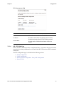
Syslog filter
ShoreTel support will specify which filter to use.
Management Source Address
Must never be set.
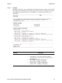
Set Hostname
Configure the host name of the system to be displayed on
the System page.
Admin Inactivity Timeout
(seconds)
This timer terminates login sessions that are inactive
for the number of second specified. This timer applies
to console, Telnet, and SSH logins. Changes to this
value do not affect sessions that are already open. A
value of '0' disables the inactivity timer. The largest
allowed timeout value is 86400 seconds. The default
is '0'.
Chapter 3:
3.3.1.2
Configuration
Set Link
In addition to allowing a user to set the link rate for Ethernet interfaces on the system, Set Link
also displays the link settings for all the Ethernet interfaces on the system. Please use caution
when adjusting the ethernet link rate as incompatible rate setting may render the device
unreachable.
Parameter
LAN Ethernet
Description
Link rate can be set to the following values:
•
•
•
•
•
Autonegotiate - The system negotiates with the
connected device and sets the best possible rate for
the Ethernet port.
10baseT-HD - 10 Mbps at half duplex
10baseT-FD - 10 Mbps at full duplex
100baseT-HD - 100 Mbps at half duplex
100baseT-FD - 100 Mbps at full duplex
VPN Concentrator Installation and Configuration Guide
19
Configuration
Chapter 3:
Parameter
3.3.1.3
Description
WAN Ethernet
Same as for LAN Ethernet
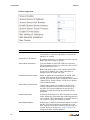
Set WAN MTU Size
This value can be adjusted to reduce the latency introduced
by large data packets on a slower link.If the WAN
upstream bandwidth is less than 256 Kbps, the MTU size
is automatically reduced to 800 bytes.
The default value for this parameter is 1500 bytes for static
IP addresses. PPPoE links negotiate the value
automatically which can be overwritten using this
parameter.
Management Interface (VPN Concentrator 5300 Only)
The out of band management port (Port 3) can be enabled and configured to allow access to
the system for configuration purposes only through this port. Once enabled, HTTP, SSH,
SNMP, and TELNET sessions will only be allowed through this port and will no longer be
available on LAN (Port 1) and WAN (Port 2) ports.
Parameter
Description
Enable Management Interface
Check to enable the Management Interface
Management Interface IP Address
Valid IP address to be assigned to the Management
Interface
Note:
This IP address must be on a different subnet than the
WAN or LAN interfaces.
Subnet Mask
20
Chapter 3:
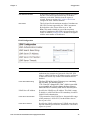
3.3.1.4
Configuration
Route
Parameter
3.3.1.5
Description
IP Network
Network address of the subnet
Netmask
Subnet mask for the subnet
Gateway
IP address of the gateway router connecting to the subnet
Delete Route
If an entry found in the route table for the information
given in “IP Network”, “Netmask”, and “Gateway”, then it
will be deleted.
VLAN
VLAN can be configured to create virtual interfaces on the VPN Concentrator so that it can be
a part of multiple broadcast domains. With proper route table setup, the VPN Concentrator can
route data between multiple broadcast domains that it is a member of. The VPN Concentrator
4500 can also do port based VLANs which enables it to tag untagged data coming from a port.
VPN Concentrator Installation and Configuration Guide
21
Configuration
Chapter 3:
VPN Concentrator 4500
LAN port 4 can only do port based VLAN. LAN ports 1 through 3 can do both tag based or
port based VLAN.
Parameter
22
Description
ID
VLAN ID to be used for the new VLAN
IP Address
IP address of the VPN Concentrator in the broadcast
domain associated with the VLAN ID being created.
Network Mask
Network mask of the broadcast domain for the new
VLAN.
LAN Port Membership
Associates the newly created VLAN to a port. Port based
or tag based VLAN can be selected by using the dropdown menu for each port. Choose 802.1 for port based
VLAN and 802.1q for tag based VLAN.
Chapter 3:
Configuration
VPN Concentrator 5300
Parameter
3.3.1.6
Description
VLAN ID
VLAN ID to be used for the new VLAN
IP Address
IP address of the VPN Concentrator in the broadcast
domain associated with the VLAN ID being created.
Network Mask
Network mask of the broadcast domain for the new
VLAN.
SSL VPN Main Page
Choose “Stunnel” submenu from the “Configuration Menu.” A submit on this page will restart
network services along with Stunnel service and all the SSL VPN sessions will be terminated
at that point.
The main configuration page is divided into the following sections:
•
•
•
•
Global Configuration
LDAP Configuration
Stunnel Firewall Configuration Proxy ARP Configuration
Stunnel IP Pool
VPN Concentrator Installation and Configuration Guide
23
Configuration
Chapter 3:
Global Configuration
Parameter
24
Description
Stunnel Enable
Enable or disable SSL VPN service on the VPN
Concentrator. A valid Server IP Address is required for
Stunnel to be enabled.
Stunnel Server IP Address
IP Address of Stunnel server listening to clients’ requests.
Note: This filed is empty by default.
Stunnel Server Port Number
TCP port number to which SSL VPN Server listens to.
This port number can have any value from 1025 to 65535,
but the default value is 443.
Note: If the default value of 443 is chosen, the HTTPS
access will be disabled. Also, if this port number is
changed, a network restart will occur.
Enable Stunnel Server Timeout
Enable or disable the session timeout for all SSL VPN
sessions. This value can be specified in number of
seconds. By default this feature is disabled, and if enabled
“Stunnel Server Tunnel Timeout” will be set to a default
value of 86400 seconds.
Stunnel Server Tunnel Timeout
Timeout value specified in seconds for all SSL VPN
sessions. The default value is 86400 seconds (one day).
Any SSL VPN session established for the specified
number of seconds specified in this parameter will be
terminated.
Enable TCP No Delay
If checked, the Stunnel server will send packets to remote
clients without any delay rather than coalescing packets to
save overhead. This is important for voice traffic since it is
very sensitive to delay. It is enabled by default.
MAC Whitelist Validation
If this feature is enabled, and if a MAC address received in
the SSL VPN client request does not match any of the
MAC addresses on the MAC whitelist, then the request is
rejected. Please see section MAC Address Whitelist to
configure the MAC whitelist database.
Chapter 3:
Configuration
Parameter
Description
MAC Blacklist Validation
If this feature is enabled, and if a MAC address received in
the SSL VPN client request matches any of the MAC
addresses on the MAC blacklist, then the request is
rejected. Please see section MAC Address Blacklist to
configure the MAC blacklist database.
Max Clients
This field specifies the maximum number of simultaneous
SSL VPN sessions supported by the VPN Concentrator.
By default the value of max clients is set as '100'.
Note: This number should not exceed the maximum
number of simultaneous SSL VPN sessions allowed by the
license. In addition, Stunnel IP Pool should be configured
with the same number of IP addresses.
LDAP Configuration
Parameter
Description
LDAP Authentication Enable
Enable or disable the LDAP authentication feature to
authenticate the username and password of the SSL VPN
client. A valid LDAP Server IP Address must be configured
to enable this feature. By default LDAP authentication is
disabled.
LDAP Search Base String
The base DN of the Active Directory tree containing
the user data. The default string is
"CN=Users,DC=domain,DC=com" which is provided
as an example only. Please change the base string to
match the DN of currently used Active Directory tree.
LDAP Server IP Address
Specifies the LDAP Server IP Address. This field is empty
by default. A valid LDAP Server IP is mandatory in order to
enable LDAP Authentication.
LDAP Server Port Number
TCP port number of the LDAP Server. the permissible range
of this parameter is 1025-65535, but the default value of
Server port is 389.
LDAP Server Timeout
Specifies the LDAP search timeout. If LDAP server doesn't
respond within the specified time, then the SSL VPN client’s
request is rejected.
VPN Concentrator Installation and Configuration Guide
25
Configuration
Chapter 3:
Proxy ARP Configuration
Parameter
Enable Stunnel Proxy ARP
Description
Proxy ARP is used to create a bridge between phones on the
LAN side and the phone connected through SSL VPN. The
VPN Concentrator uses its own MAC address to receive the
IP packets on behalf of all the remote phones and then routes
the IP packets to the remote phones.
Stunnel IP Pool
IP address pool specifies the number of IP addresses available to be assigned to each SSL
VPN client.The permissible format is to specify a valid IP address or a range of IP Addresses,
for example 10.10.10.2 or 10.10.10.2-100. Overlapping IP Address ranges are not supported.
Care must be taken to isolate the peer IP Address pool from the configured Server IP Address.
It is important to remember that every incoming session requires a unique IP Address to be
assigned from the IP Pool. If the numbers of addresses in the pool are not adequate, it imposes
a limitation on the max simultaneous Stunnel connections, irrespective of configured 'Max
Clients' parameter value. By default, this list is empty. If you have added some value in IP pool
range, it will only become effective after the next restart of Stunnel.
Note: Remove addresses from the DHCP server or servers on the LAN that will be used by
the VPN Concentrator’s address pool. The IP address pool must be part of the VPN LAN
subnet, and must not overlap with the pool used by the DHCP server on the same subnet.
3.3.1.7
SSL VPN Databases
The SSL VPN service makes use of the following databases:
•
•
•
•
26
Username Database
MAC Address Whitelist
MAC Address Blacklist
Active Sessions
Chapter 3:
Configuration
Username and Password Database
The incoming Stunnel client request is authenticated against the username-password database.
The Username’s List page allows system administrators to create a database of Usernames and
Passwords to be used for client request authentication. The Stunnel Username-Passwords
database has following characteristics:
•
•
•
•
•
The maximum number of Username-Passwords that can be registered at a time is
1000.
The maximum length allowed for both Username and Password is 16 characters.
Empty strings are not allowed for both Username and Password.
Duplicate Username configuration is not allowed.
The permissible character set for Username and Password is - 'A' to 'Z', 'a' to 'z', '0' to
9' and Printable characters as listed: `~!@#$%^& *()-_=+{}[]|:;"'<>,.\/?
To add or delete a user from the database, choose “Stunnel” submenu from “Configuration
Menu” and then choose “Username Database” submenu of “Stunnel.”
Note: the VPN user name & password are independent of any user names and passwords set
in ShoreWare Director for ShoreTel phone users.
VPN Concentrator Installation and Configuration Guide
27
Configuration
Chapter 3:
MAC Address Whitelist
If MAC Whitelist validation is enabled for STUNNEL, the MAC Address sent by the client is
validated against the configured MAC Address Whitelist. If the MAC Address is not present
in the Whitelist then the session request is rejected.
The maximum number of MAC Addresses that can be configured at a time in the Whitelist
database is 1000. Only valid MAC addresses are allowed. Duplicate MAC Addresses cannot
be configured. If MAC Blacklist validation is enabled, then MAC Blacklist validation is done
prior to MAC Whitelist validation.
To add or delete MAC addresses from the database, choose “Stunnel” submenu from
“Configuration Menu” and then choose “MAC Whitelist” submenu of “Stunnel.”
MAC addresses can be entered in the following format:
HH:HH:HH:HH:HH:HH[/X], where “H” is a hexadecimal digit from 0 to F.
The optional part /X specifies the number of hex digits from right to left. X can
be between 1 to 12.
Example: 12:34:56:78:90:AB/3 would match all the MAC addresses in the range
of 12:34:56:78:90:00 to 12:34:56:78:9F:FF
28
Chapter 3:
Configuration
MAC Address Blacklist
If MAC Blacklist validation is enabled for STUNNEL, the MAC Address sent by the client is
validated against the configured MAC Address Blacklist. If the MAC Address is present in the
Blacklist then the session request is rejected.
The maximum number of MAC Addresses that can be configured at a time in the Blacklist
database is 1000. Only valid MAC addresses are allowed. Duplicate MAC Addresses cannot
be configured. If MAC Whitelist validation is enabled, MAC Whitelist validation is done after
MAC Blacklist validation.
To add or delete MAC addresses from the database, choose “Stunnel” submenu from
“Configuration Menu” and then choose “MAC Blacklist” submenu of “Stunnel.”
MAC addresses can be entered in the following format:
HH:HH:HH:HH:HH:HH[/X], where “H” is a hexadecimal digit from 0 to f.
The optional part /X specifies the number of hex digits from right to left. X can
be between 1 to 12.
Example: 12:34:56:78:90:AB/3 would match all the MAC addresses in the range
of 12:34:56:78:90:00 to 12:34:56:78:9F:FF
VPN Concentrator Installation and Configuration Guide
29
Configuration
Chapter 3:
Current Sessions
The Active Stunnel Session(s) page lets the administrator view or terminate the active
STUNNEL sessions. Each Active STUNNEL session is associated with a unique Username
and MAC address as shown in the table. The timestamp and duration fields display the time
the session was established and the amount of time the session has been active.
3.3.2
Configuring VPN Parameters on IP Phones
All ShoreTel IP Phones that support the VPN feature need to be configured to be aware of the
VPN Concentrator as well as how to authenticate with this device.
Two methods are provided:
1. Via MAC Address specific IP Phone configuration files.
2. Manual configuration using the Phone User Interface.
The latter method is only suggested for small deployments or demonstration purposes.
3.3.2.1
Configuration via config files
The following table shows the relevant parameters
#Keepalive parameter overrides 0 set in shore_s6g.txt file
KeepAlive 120
#DnsAddress- List of up to 2 DNS Server Addresses in dotted decimal format.
# Sources are MAN and DHCP. Defaults is 0.0.0.0
#VpnGateway- List of up to 3 IP address for the VPN Gateway in dotted decimal
or FQDN format.
# Sources are MAN (dotted decimal only) and CFG. Default is 0.0.0.0
VpnGateway 74.125.19.99, 74.125.19.100
30
Chapter 3:
Configuration
#VpnPort- Port to use when contacting the VPN Gateway. Sources are MAN, CFG.
Default is 443.
VpnPort 443
#VpnEnable- Enable VPN Client if set to 1. Sources are MAN, CFG. Default is 0
#VpnUserPrompt- Don’t cache the authentication user in NVRAM for survival
across reboots if set to 1.
# This will force user entry after all power on events, but will permit automatic restoration of
# dropped links without user intervention. Sources are MAN, CFG. Default is 0.
VpnUserPrompt 0
#VpnPwPrompt- Don’t cache the authentication password in NVRAM for survival
across reboots if set to 1.
# This will force password entry after all power on events, but will permit automatic restoration of
# dropped links without user intervention. Sources are MAN, CFG. Default is 0.
VpnPwPrompt 0
#TcpKeepAlive-Number of seconds between TCP KeepAlive transmissions. The
number maybe adjusted from 10 to 3600 seconds. Sources are CFG. Default is 60
seconds.
TcpKeepAlive 70
3.3.2.2
Manual configuration
Step 1:
With the phone on hook, press the Mute button. The LED should not
light and you shouldn't hear any tones; if this isn't the case, lift and
replace the handset.
Step 2:
Dial S-E-T-U-P on the keypad and then press the # key. When
prompted, enter the assigned password for the telephone followed
by the # key.
Step 3:
Press the # key to skip clearing all configuration values
Step 4:
Press the # key to cycle through the configuration values until
prompted to enter the VPN Gateway parameter
VPN Concentrator Installation and Configuration Guide
31
Configuration
Chapter 3:
Step 5:
Enter the following VPN related parameters in order
1. VPN Gateway. [Default value = 0.0.0.0]. This is the IP Address of
the VPN Concentrator the phone will connect with. Use the digit
keys to enter digits and the * key to enter a period in the IP address
(.) Press the # key to complete this entry
2. VPN Port. [Default value = 443]. This is the port number on the
VPN concentrator that the phone will connect to. Press the # key to
accept the default value or use the digit keys to enter a different
port number followed by the # key to complete this entry.
3. VPN [Default = Off]. This setting enables/disables the VPN
feature on the phone. Press the * key to toggle the current setting if
needed. Press the # key to accept the current setting.
4. VPN User Prompt [Default = Off]. If Enabled the user will be
prompted to enter their VPN user name after a power cycle of the
phone. If Disabled, the user name is saved in non-volatile RAM
and is submitted automatically after a power cycle.
This setting does not affect the phone’s behavior in which it will
automatically attempt to re-establish the VPN tunnel should it be
disconnected while the phone is powered on.
Press the * key to toggle the current setting if needed. Press the #
key to accept the current setting.
5. VPN Password Prompt [Default = Off]. If Enabled the user will be
prompted to enter their VPN authentication password after a power
cycle of the phone. If Disabled, the password is saved in nonvolatile RAM and is submitted automatically after a power cycle.
This setting does not affect the phone’s behavior in which it will
automatically attempt to re-establish the VPN tunnel should it be
disconnected while the phone is powered on.
Press the * key to toggle the current setting if needed. Press the #
key to accept the current setting.
3.3.2.3
Summary of recommended configuration and deployment procedure:
• Enter the phone's MAC address, associated username and password into the VPN
Concentrator’s database.
32
•
Configure the phones using the preferred method of MAC address specific
configuration files. Note: since there is no user specific configuration relating to
VPN’s, a master configuration may be created that is then replicated for each MAC
address as needed.
•
Power-up the phone on the corporate (local) network with the VPN setting to Off
(Refer to manual setting). This will cache the config file with the VPN settings in the
phone.
•
Set VPN to ON via the on-screen Setup menu and verify a successful VPN connection
via a public internet connection.
•
Phone is shipped to remote location and should automatically establish the VPN
connection when connected to the users’s home or remote office network assuming
DHCP operation.
Chapter 3:
Configuration
This procedure allows for a turn-key installation of remote phones with minimal user
intervention.
VPN Concentrator Installation and Configuration Guide
33
Configuration
34
Chapter 3:
Chapter 4:
Tools and Troubleshooting
C H A P T E R
4.1
4
Tools and Troubleshooting
Tools offered through the GUI and Command Line Interface (CLI) can be used to troubleshoot
the system. Sometimes both GUI and CLI need to be used to debug the problem. Logging into
the GUI system has been explained earlier in Section 1.2.1.5 and Section 1.2.2.5. CLI can be
accessed through Serial interface, SSH, or Telnet. To log into the CLI system, type in “root”
for “login as:” prompt and “@#$%^&*!()” (While holding shift key 23456781890) for the
“password:” prompt.
VPN Concentrator Installation and Configuration Guide
35
Tools and Troubleshooting
4.1.1
Chapter 4:
Network Information
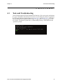
Network information is available through both GUI and CLI. Following screenshot displays
the network information such as routing tables, link status, and interface status:
Please make sure that all links and interfaces are up and running and all interfaces have valid
IP addresses. Also make sure that the default route is pointing to the right gateway.
36
Chapter 4:
Tools and Troubleshooting
Interface information can also be obtained through the CLI by issuing the “ifconfig”
command.
4.1.2
Network Connectivity
Once all the physical and logical interfaces are up and running then network connectivity can
be checked by using the ping command. "traceroute" command can also be used to have an
understanding about the path that a packet will take to reach a destination on the internet and
the delay associated with it.:
VPN Concentrator Installation and Configuration Guide
37
Tools and Troubleshooting
Chapter 4:
“ping” command is also available in CLI:
•
•
•
•
•
•
# ping 4.2.2.2
PING 4.2.2.2 (4.2.2.2): 56 data bytes
64 bytes from 4.2.2.2: icmp_seq=0 ttl=53 time=46.5 ms
64 bytes from 4.2.2.2: icmp_seq=1 ttl=53 time=44.7 ms
64 bytes from 4.2.2.2: icmp_seq=2 ttl=53 time=45.6 ms
64 bytes from 4.2.2.2: icmp_seq=3 ttl=53 time=45.6 ms
• --- 4.2.2.2 ping statistics --• 4 packets transmitted, 4 packets received, 0% packet loss
• round-trip min/avg/max = 44.7/45.6/46.5 ms
• Note: Stop ping with <Ctrl>+<C>
Following is an example of “traceroute” command being used in CLI:
• # traceroute 4.2.2.2
• traceroute to 4.2.2.2 (4.2.2.2), 30 hops max, 40 byte packets
• 1 12.48.203.1 (12.48.203.1) 0.488 ms 1.21 ms 0.458 ms
• 2 12.48.202.1 (12.48.202.1) 1.887 ms 1.906 ms 1.069 ms
• 3 12.86.182.205 (12.86.182.205) 22.676 ms 29.457 ms 30.186 ms
• 4 tbr1.phmaz.ip.att.net (12.122.108.6) 47.213 ms 45.362 ms 45.755 ms
• 5 cr1.phmaz.ip.att.net (12.122.22.129) 45.786 ms 45.427 ms 44.744 ms
• 6 cr1.dlstx.ip.att.net (12.122.28.181) 45.514 ms 45.032 ms 45.676 ms
• 7 tbr1.dlstx.ip.att.net (12.122.18.170) 45.212 ms 45.951 ms 46.553 ms
• 8 ggr3.dlstx.ip.att.net (12.123.16.193) 44.147 ms 46.473 ms 45.071 ms
• 9 192.205.35.142 (192.205.35.142) 44.002 ms 43.942 ms 45.102 ms
• 10 vlan79.csw2.Dallas1.Level3.net (4.68.19.126) 57.607 ms 45.019 ms
vlan69.csw1.Dallas1.Level3.net (4.68.19.62) 52.957 ms
• 11 ge-10-0.core1.Dallas1.Level3.net (4.68.122.8) 45.031 ms ge-11-0.core1.Dallas1.Level3.net
(4.68.122.40) 45.005 ms ge-10-0.core1.Dallas1.Level3.net (4.68.122.8) 45.258 ms
• 12 * * *
• 13 * * *
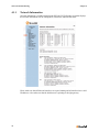
4.1.3
Viewing Log Files
To help debug the problems, help files can be viewed by issuing the following commands:
•
To view the system messages issue the command
“tail –f /var/log/messages”
•
To view the Stunnel related messages issue the command
“tail -f /var/log/stunnel_history.log”
These files can also be provided to ShoreTel support team for debugging purposes. In addition
ShoreTel’s remote system log server information can be entered in the “Services
Configuration“so that ShoreTel support team can analyze it for debugging purposes. If more
information is required for debugging purposes then read the “Packet Capture” section.
38
Chapter 4:
4.1.4
Tools and Troubleshooting
Packet Capture
Packet capture capability can be used to capture packets and analyze them for debugging
purposes. This capability is only available through CLI. Packets can be filtered for capture by
on the basis of host, port, interface, etc. The captured packets are stored in a file in on RAM
disk in the VPN Concentrator with the extension “pcap”. Packets can be captured on eth0
(LAN port), eth1 (WAN port), and pppX (where X is a positive integer). pppX is the interface
that is associated with a remote phone.
4.1.4.1
Capturing Packets for an Individual SSL Connection
Packets will need to be captured on eth0, eth1, and pppN (where N is a positive integer) for an
individual SSL connection. Following steps need to be taken to capture the packets for a given
SSL VPN connection:
1. Identify the PPP session associated with a given phone by obtaining the IP address
of the phone from the “Active Sessions” by using its MAC address. Once the IP
address of the phone has been identified, then use the “ifconfig” command to find
the PPP interface that has the phone’s IP address.
2. Create the disk space to store the captured information by issuing the following
command: “mount –t tmpfs tmpfs /etc/images –o size=8m”
3. Capture the packets on eth0, eth1, and ppp0 (assuming that ppp0 has the same IP
address as the phone) by using the following command: “tcpdump -s 0 -ni ppp0 -w
/etc/images/PPP0.pcap & tcpdump -s 0 -ni eth0 host <private IP of Phone> -w /etc/
images/ETH0.pcap & tcpdump -s 0 -ni eth1 host <WAN public IP address> –w /etc/
images/ETH1.pcap”
4. Next, stop the packet capture by issuing the following command: “killall tcpdump”
5. FTP the captured file “/etc/images/ETH1.pcap” to remote server so that it can be
viewed by a program like “wireshark” or sent to ShoreTel support team for analysis.
VPN Concentrator Installation and Configuration Guide
39
Tools and Troubleshooting
40
Chapter 4: