1
TE
CHEROKEESIX3OO
INFORMATION
MANUAL
,t
il
-lqo3f,h#',,*(at4
CHEROKEESIX 3OO
a1h"
{o
\/' af
INFORMATION
j-
--/
MANUAL
CherokeeSix 3OO
PA-32-300
HANDBOOK
PARTNO.761-559
A complete or partial replacement of this manual, Part No.
7 61 559, may be obtained only from Piper Customer Services.
Publishedby
PUBLICATIONSDEPARTMENT
PiperAircraft Corporation
7 6 15 s 9
Issued:July 1973
u
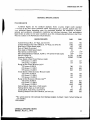
APPLICABILITY
The aircraftserialnumbereligibilitybracketfor applicationof this manualis 32-7aa0001
The specificapplicationof this manualis limited to the Piper PA-32-300
rhrough32-7640130.
designated
by serialnumberand registrationnumberon the backof the title page
modelairplane
this
manual.
of
This manualcannotbe usedfor operationalpurposesunlesskept in a currentstatus.
REVISIONS
The information compiledin the Pilot'sOperatingManualwill be kept currentby revisions
distributedto the airplaneowners.
Revision material will consist of information necessaryto update the text of the present
manualand/orto add informationto coveraddedairplaneequipment.
I.
Revisions
Revisionswill be distributed whenevernecessaryas complete page replacementsor
additions and strallbe insertedinto the manualin accordancewith the instructionsgivenbelow:
l.
2.
3.
II.
Revisionpageswill replaceonly pageswith the samepagenumber.
Insert all additional pagesin proper numericalorder within eachsection.
Pagenumbersfollowed by a smallletter shall be insertedin direct sequence
with the
samecommonnumberedpage.
Identificationof RevisedMaterial
Revisedtext and illustrationsshall be indicatedby a blackverticalline alongthe left hand
margrn of the page, opposite revised,added or deleted material. A line oppositethe page
number or section title and printing date, will indicate that.the text or illustration was
unchangedbut material wasrelocatedto a different pageor that an entire pagewas added.
Black lines will indicateonly current revisionswith changesand additionsto or deletions
of existingtext andillustrations.Changes
in capitalization,spelling,punctuationor the physical
location of materialon a pagewill not be identifiedby symbols.
III.
Original PagesIssued
The original pagesissuedfor this manualprior to revisionaregivenbelow:
l-l through 14,2-1 through 2-19,3-l through3-18,4-l through+7,5-1 through5-30,
7-l through7-12,8-l through8-2,9-l through9-12,lGl through10-15.
ltr
(lFC(II{TEI{TS
TABLE
GE}IERAI
SPECIFICATIO}IS
. AIRPLAIIE
A}ID
SYSTEMS
DESCRIPTI(I}I
T.A.A.
FUGHI
MAIIUAI
APPR(IYED
AIRPLA]IE
I.A.A.APPROYEII
PROCEDffiES
EilIERGE}ICY
EMERGENCY
PROCEDURES
A}ID
ITHGHT
BAtAilCE
lilsTRucn(Iils
L(lADtitG
INSTRIICTIONS
OPERATINO
(lPilATING
TIPS
CHARTS
PERF(IRMAIICE
A}ID
SERYICING
HAilDLI}IG
GElt
ERAt
SPECtHCATt0ItS
Performance
Weights
PowerPlant .
Fuel and Oil . .
Baggage
Area
Dimensions
LandingGear
3-View
l-l
l-2
1-2
l-2
l-2
l-3
l-3
l-4
CHEROKEESIX.3OO
GENERAL SPECIFICATIONS
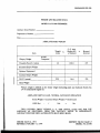
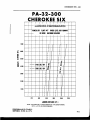
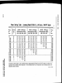
PERFORMANCE
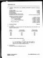
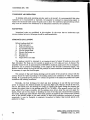
Published ftgures are for standard airplanes flown at gross weight under standard
:c;rditions at sea level unlessotherwisestated. Performancefor a specificairplanemay vary
;rom publishedfigures dependingupon the equipmentinstalled,the conditionsof engines,
airplane and equipment, atmosphericconditions and piloting technique.Each performance
figure below is subjectto the sameconditionsason the corresponding
performancechartfrom
which it is takenin the PerformanceChartsSection.
GROSSI{EIGHTS
3400
2900
TakeoffGroundRun, l0 o flaps,sealevel(ft)
Takeoff DistanceOver 5Gft Obstacle,l0 o flaps,sealevel(ft)
BestRateof Climb Speed(mpnl
Rateof Climb(ft per min)
BestAngleof ClimbSpeed(mph)
Max Speed,sealevel(mph)
Max SpeedOptimumAltitude,8,300ft,757opower(TAS)(mph)
ServiceCeiline(ft)
AbsoluteCeiling(ft)
CruiseSpeedat BestPowerMixture (mph)
657oPower,I 1,500ft
55%power,15,000ft
Rangeat BestPowerMixture(mi1**
75% power,8,000 ft
657opower,I 1,500ft
55%power,15,000ft
CruiseSpeedat BestEconomyMixture (mph)
757opower,8,000 ft
657opower, I 1,400ft
5570power,15,000ft
Rangeat BestEconomyMixture(mi;**
7 5% power, 8,000 ft
657opower, I 1,400ft
55%power,15,000ft
StallingSpeed,flapsdown,(CAS) (mph)
StallingSpeed,flapsup, (CAS)(mph)
LandingRoll, flapsdown, sealevel(ft)
LandingDistanceOver 5&ft Obstacle,sealevel(ft)
1050
I 500
105
1050
95
l?4*
168*
16,250
18,000
750
I 200
100
1350
175*
l7l*
20,000
21.500
t63
155
t67
163
780
845
905
779
850
935
t66
159
149
169
165
t57
850
945
1030
865
980
1080
63
7r
630
1000
s8
66
540
850
*The speedstatedis with optional wheelfairingsinstalled.Subtract 3 mph if wheel fairings are
not installed.
**No reserve.
GEMRAL SPECIFICATIONS
ISSUED:JULY 12,1973
1-1
CHEROKEESIX.3OO
GROSSWEIGHTS
3400
2900
WEIGHTS
StandardEmpty Weieht(lbs)
MaximumUsefulLoad (lbs)
t824
1516
1824
to16
POWERPLANT
Engine.Lycoming
''
RatedHorsepower
RatedSpeed(rpm)
Bore(inches)
Stroke(inches)
(cubic inches)
Displacement
Ratio
Compression
Dry Weight(pounds)
Propeller (Standard)
(Serialnos. 7440O01 through 76 4Q065 and 7 64.046:7
through
76400',7r)
rO-s4GKlAs
(serialnos.7640066,7640072andup) IO-54SKlG5
300
2700
) . lz)
4.3',15
541.5
8 ' 7 :I
45'l
HC-C2YK-I( ) | 847s-4 or HC{2YK-r( )| 8475D-4
or HC-C2YK-I( )F/F8475D-4
(Optional)*
HC{2YK-I( )/847sR4 orHC{2YK-I( )F/F8475R-0
80
PropellerDiameter(inches)(Standard)
(Optional)
84
FUEL AND OIL
Fuel Capacity(inboard)(U.S. gal)
With StandardAuxiliary (U.S. gal)
Oil Capacity(U.S. qts)
Fuel, Aviation Grade(min octane)
50
84
t2
10 0/l3o
BAGGAGE
(lbs)
Maximum Baggage
(cubic
Baggage
Space
ft)
Door Size(in.)
Baggage
Forward
Aft
100
8
16x22
100
20
*Serialnos.7440001thru 7540188only
GENERAL SPECMCATIONS
REVISED: FEBRUARY 2, 1916
.ll
CHEROKEESD(-3OO
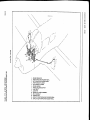
DIMENSIONS
f
ir
Wing Span (ft)
Wing Area (sq ft)
Wing Loading (lbs per sq ft)
Length (ft)
Height (ft)
Power Loading (lbs) per hp)
32 . 8
1 74 . 5
19.5
27.7
8.2
I 1.3
LANDING GEAR
WheelBase(ft)
WheelTread(ft)
(lbs)
Tire Pressure
GENERAL SPECIFICATIONS
ISSUED:JULY l2,t97g
Nose
Main
7.8
10.6
28-30
35-40
1-3
CHEROKEESIX.3OO
32'8.t5"
I
t4
,,0.,r'
GENERAL SPECIFICATIONS
ISSUED:JULY 12.1973
DESCRIPTI(III
AIRPLAIIE
AllDSYSTEI'IS
.
The Airplane
Airframe
Engineand Propeller
In d u cti onS ystem
LandingGear
Flight Controls
Fuel System
ElectricalSystem
VacuumSystem
InstrumentPanel
Pitot-StaticSystem
Heatingand VentilatingSystem
CabinFeatures
Area
Baggage
Stall Warning
Finish
Air Conditioning
PiperExternalPower
2-l
2-l
2- l
.. .;
aa
L-L
2-4
2-6
a1
2-9
2-t3
2-13
2-t5
2-15
2-r5
2-r8
2-t8
2-18
2-r8
2- t9
2-i
CHEROKEESIX . 3OO
DESCRIPTION
AIRPLANE AND SYSTEMS
THE AIRPLANE
The PA-32-300is a six-place(seventhseat optional),single-engine,
low-wing.all metal
seatsgivetheairplanea widerangeof cargoandpassenger
monoplane.Removable
loadingoptions.
andpowerfulfuelinjected300horsepowerengine.
Its largecapacity,combinedwith an economical
rnakesthis Cherokeea versatileairplanefor personalor commercialuse.
AIR FR AME
Exceptfor the tubularsteelenginemount,steellandinggearstruts,othermiscellaneous
steel
parts,and the dentresistantfiberglassextremities- cowlingand tips of wingsand tail surfaces- the
basicairframeis of aluminumalloy.
The fuselageis a conventionalsemi-monocoque
structurewith a cabindoor on the right front
and a cargoand passenger
door on the left rear.
The wings are attachedto eachsideof the fuselageby the insertion'ofthe butt endsof the
mainsparsinto a spar box carry-throughwhich is an integralpart of the fuselagestructure.This
provides,in effect,a continuousmain sparwith splicesat eachsideof the fuselage.
Therearcalso
fore and aft attachmentsat the rear sparand at an auxiliary front spar.
The wing airfoil sectionis a laminarflow type,NACA65r4l5 with a maximumthickness
.
at
about 40Voaft of the leadingedge.
The empennage
consistsof the fin, the stabilator,and the stabilatortrim tab.
ENGINE AND PROPELLER
The Lycoming lO-5{0'KlA5 (Serial nos. 7440001through 7640065and 7640067through
'7ffi71 or lO-540-KlG5(Serialnos.764+Cf,66,7640072and
up) engineinstalledin the PA-32'300is
ratedat 300horsepowerat 2700rpm. This enginehasa compression
ratio of 8.7to I and required
100/130minimumoctanefuel.Theengineisequippedwith a gearcdstarter,a60amperealternator,
dual magnetos,vacuumpump drive, a vane-typefuel pump, and fuel injection.
The exhaustsystemconsistsofdual exhauststacksroutedto a singleheavygaugestainless
steel
muffler on serialnumbers7440001through7540188.On later modelsindividualexhaustpipesare
routed in pairsto threeheavygaugestainlesssteelmufflers.Exhaustgasesare routedoverboardat
the undersideof the enginecowling.The muffler (or mufflers)are surroundedby a shroudwhich
providesheat for the cabin and for windshielddefrosting.
Cowling on the CherokeeSix is designedto cool the enginein all normal flight conditions.
includingprotractedclimb, without the useof cowl flapsor coolingflanges.
AIRPLANE AND SYSTEMS
REVfSED: FEBRUARY 2. 1976
2-l
C H ER OK E S
E IX .3 OO
Theconstantspeedpropelleris a HartzellHC-C2YK-I ( )F/ F8475D-4with a diameterof 80
inches.Thepropelleris controlledby a governormountedat theleftforwardsideof thecrankcase
.
The governoris operatedby a cablefrom the powercontrol quadrant.
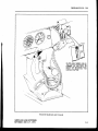
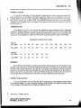
The power control quadrantlocatedin the lower centerof the instrumentpanelincludes
throttle,mixture.and propellercontrols.A friction lock on the right sideof thequadrantprevents
creepingof the controls.In addition.the mixturecontrolhasa lock* to preventactivationof the
mixture control insteadof the pitch control.For informationon the leaningprocedure,
seethe
Avco-LycomingOperator'sManual.
INDUCTION SYSTEM
On SerialNumbers74y',0001
through7540188,
the InductionAir for the engineentersan
openingin thenosecowlbelowthepropellerand is pickedup by a largeair duct.Theair isdirected
through a filter and on to the servoregulator.Shouldthe filter becomeblocked,a springJoaded
door in the air box betweenthe lilter and the servoregulatoropensautomatically.
Thedoor may
also be openedmanuallyby a control locatedon the right sideof the quadrant.
,,: Qn SerialNumbers764000| and up, an inductionscoopis locatedon the left sideof the lower
cbwl. An intakeair box is attachedto the insideof the cowl adjacentto theair filter box. The filter
box is locatedat the aft end of the induction scoop. Accessto the filter is gainedthrough a
detachableplate locatedon the outsideof the lower cowl. The intake air box incorporatesa
manuallyoperatedtwo-wayvalvedesignedto allow inductionair eitherto passthroughthefilter or
to bypassthe filter and supplyheatedair directly to the engine.
Alternateair selectioninsuresinductionair flow shouldthefilter becomeblocked.Sincetheair
is heated,the alternateair systemoffersprotectionagainstinductionsystemblockagecausedby
snow or freezingrain, or by the freezingof moistureaccumulatedin the induction air filter.
Alternateair is unfiltered;therefore,it shouldnot be usedduring groundoperationwhendust or
other contaminantsmight enter the system.The primary (through the filter) induction source
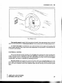
shouldalwaysbe usedfor takeoffs.On serialnumbers7640001and up, the controlis operatedby
pressingthe knob to the left to clear the retaininggateand then movedin the desireddirection.
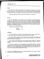
The BendixRSA-lOEDI type fuel injectionsystemconsistsof a servoregulatorwhichmeters
fuel flow in proportion to airflow to the engine,giving the properfuel-air mixture at all engine
speeds,and a fuel flow divider which receives
the meteredfuel and accuratelydividesthe fuel flow
amongthe individualcylinderfuel nozzles.
A combinationfuel flow indicatorand manifoldpressure
gaugeisinstalledin theleft sideof the
instrumentpanel.The fuel flow indicatoris connectedto the fuel flow dividerand monitorsfuel
pressure.
The instrumentconvertsfuel pressureto an accurateindicationof fuelflow in gallonsper
hour and percentageof cruisepower.
fSerialnos.7540001
and up
2-2
AIRPLANE AND SYSTEMS
REYISED:JULY 17.l97S
CHEROKEESIX.3OO
oN sER. NOS.7640m1 AND UP,
THE CONTROL KNOB MUST BE
PRESSED TO THE LEFT TO
CLEAR THE RETAINING GATE
P R I O R T O S E L E C T I N G TH E
D E S I R E DP O S I T I O N .
: -_------:::::\
fir--Em
Throttle Quadrantand Console
AIRPLANE AND SYSTEMS
REVISED: ruLY 17,1975
CHEROKEESIX.3OO
LANDING GEAR
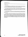
All three landinggearuseCleveland6.00 x 6 wheels.The main gearhavebrakedrumsand
Clevelanddouble disc hydrualic brakeassemblies.
The nosewheel carriesa 6.00 x 6 four or six
ply tire and the main gearuse6.00 x 6 six ply tires.All threetires aretube type.
The nosegearis steerableusinga combinationof full rudder pedaltraveland brakes.The
nose gearcan be tumed 24o eachside of center.A springdeviceis incorporatedin the rudder
pedaltorque tube assemblyto aid in rudder centeringand to providerudder trim. The nosegear
alsoincludesa shimmydampener.
The oleo struts,areof the air-oil type. The normalextensions,
arc,3-ll4 inches.
for the nose
gearand 4l 12 inchesfor the main gearunder normalstaticload (empg weightof airplaneplus
full fuel and oil).
The brakesare operatedby toe pedalsattachedto the left rudderpedalsor by a handlever
and master cylinder located below and behind the left center of the instrument sub-panel.
Optional toe brakesare availablefor the right rudder pedals.Hydraulic cylinden are located
aboveeach pedal and adjacentto the hand lever.The brakefluid reservoiris on the top left
front of the fue wall. The parking brake is incorporated in the lever brake and is engagedby
p'uling back on the lever and depressing
the knob attachedto the top of the handle.To release
the parking brake,pull back on the brakeleverto disengage
the catch;then allow the handleto
sri'ingforward.
24
NRPI.ANE AND SYSTEMS
REVISED: NOVEMBER 6, 1974
CHEROKEESIX - 3OO
;/
\
\-i-\
Main WheelAssemblv
AIRPLAI{E AND SYSTEMS
ISSUED:JULY 12,1973
CHEROKEE
SIx.3OO
Console
FUGHT CONTROLS
Dual controls,with a cablesystembetweenthe controlsand the surfaces,are installedas
standardequipment.
The horizontal tail is of the all-movableslab type (stabilator).The stabilatorprovidesextra
stability and controllabilitywith lesssize,drag,and weightthan conventionaltail surfaces.
An anti-servotab which also acts as a longitudinal trim tab, is located on the horizontal
tail. This tail is actuatedby a control mountedon the control tunnelbetweenthe front seats.
The aileronsare providedwith a differential action which tendsto eliminateadverseyaw in
turningmaneuver and to reducethe amountof coordinationrequiredin normal furns.
to
The flaps are manuallyoperated,balancedfor light operatingforces,and spring-loaded
retum to the up position. A past-centerlock incorporatedin the actuatinglinkageholds the flap
when it is in the up position so that it may be usedas a step on the right side.Sincethe flap will
not support a step load except in the full up position, it shouldbe completelyretractedwhen
the airplaneis on the ground.The flaps havethree extendedpositions,10, 25, and 40 degrees.
24
AIRPI.AI{E AI{D SYSTEMS
ISSUED:JULY 12. 1973
CHEROKEESIX . 3OO
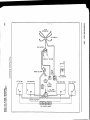
FUEL SYSTEM
The standardfuel capacityof the CherokeeSix is 84 gallons,all of which is usableexcept
for approximatelyone pint in eachof the four tanks.The two main inboardtanks,which hold
25 gallons each, ate attachedto the wing structure with screwsand nut plates and can be
removedeasily for serviceor inspection.The tip tanks are constructedof resin-impregnated
and eachone holds l7 gallons.
fiberglass,
Whenusinglessthan the standard84 galloncapacityof the tanks,fuel shouldbedistributed
equallybetweeneachside.Thetip tanksshouldalwaysbefilledfirst,andfuel from the maintanks
shouldbe usedfirst. All weightin excessof 3ll2 poundsmust be in fuel weightonly.
The fuel selectorcontrol is locatedbelow the centerof the instrumentpanelon the sloping
faceof the control tunnel. It has five positions,one position corresponding
to eachof the four
tanksplusan OFF position.
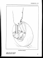
To avoid the accumulationof waterand sediment,the fuel systemshouldbe draineddaily
prior to first flight and after refueling. Each tank is equippedwith an individual quick drain
locatedat the lower inboard rear comer of the tank. The fuel strainerand a systemquick drain
valveare locatedin the fuselageat the lowest p<irintof the fuel system.It is important that the
fuel systembe drainedin the followingmanner:
Drain eachtank through its individualquick drain locatedat the lower inboardrear
l.
corner of the tank, makingsurethat enoughfuel hasflowed to ensurethe remorralof
all waterand sediment.
2. Placea container beneaththe fuel sump drain outlet locatedunder the fuselage.A
specialcontaineris fumishedfor this operation.
3. Drain the fuel strainerby pressingdown on the lever locatedon the right sideo,fthe
cabin on the forward edgeof the wing sparhousing.Move the selectorthrough the
following sequence:OFF position,left tip, left main, right main, and right tip while
draining the strainer. Make sure that enough fuel has flowed to drain the fuel line
betweeneachtank outlet and the fuel strainer,as well asthe straineritself. With full
fuel tanks, it will take approximatelyI I secondsto drain all the fuel in one of the
fuel lines from the tip tank to the strainer,and approximately6 secondsto drain all
of the fuel from the line from either main tank to the fuel strainer.When the tanks
are lessthan full, it will take a few secondslonger.
4. Examinethe contentsof the containerplacedunderthe fuel sumpdrain outlet. When
the fuel flow is free of water and sediment, close the drain and disposeof the
contentsof the bottle.
CAUTION
When draining fuel, care should be taken to ensurethat no fre
hazardexistsbeforestartingthe engine.
After using the undeneat quick drain, check from the outside to make sure that it has
closedcompletelyand is not leaking.
AIRPLANE A}.ID SYSTEMS
REVISED:DECEMBER 15. l9?t
L7
:-'i,.r:.::.
o
., :.:;ii
trt
n
o
xi!
FLOW
DISTRIBUTION
tlt
(n
X
FUELNOZZLES
a
t,
()
FUELINJECTOR
.rJ
I
THROTTLE
(!
(A
.a
o
U)
c)
(D
et
VENT
o
L EF T T IP T ANK
H
-u2F
F
ats
e>
LEFT MAIN TANK
vt2
9rd
k>
cr.ru
z
4va
-||(
N(a
' ;.1
i;fd
i<
u) ut
FUEL SELECTOR
FUEL y'
T
PRESSURE
RIGHTMAIN TANK
GAUGE FUEL
FUEL
SELECTOR
SYSTEM
CONTROL
DRAIN
LEVER
FUELTANK
/
TSELECTOR VALVE
FUEL QUANTITY
GAUGES
R IGH T TIP TA N K
CHEROKEESIX - 3OO
_\_
__=
\_
\
\\.--\
=-=\--.-\-
,/-T-
(A\---l;,{'4--l
\\ \
tfry
|
)WAa
v-\\-.
\\
mN
Lli@
s;
s
. .---..-.-.=----.....-
Fuel Drain Lever
l
Fuelquantitygauges
for eachof thefour tanksarelocatedin theenginel3ugeclusteron the left
sideof the instrumentpanel.A fuelpressure
indictorisalsoincorporatedin theenginegaugecluster.
An electricfuel pump is providedfor usein caseof failure of the enginedriven pump. The
electricpump operatesfrom a singleswitchand independent
circuitprotector.It shouldbe ON for
all takeoffsand landings.
ELECTRICAL SYSTEM
The l4-volt electricalsystemincludesa l2-volt brttery for startingand to backup alternator
output. Electricalpoweris suppliedby a 60 ampererlternaior.The battery,a masterswitchrelay,a
voltageregulatorand an overvoltagerelay are locatedbeneaththe floor of the forward baggage
compartnient,and accessis obtainedby removingthe floor.
Electricelswitchesare locatedon a panelto the pilot's left and all circuit breakersare on the
lower right instrumentpanelbehinda decorativedoor. Two thumb-wheelrheostatswitchesto the
left of the circuit breakerscontrol the navigationlightsand the intensityof the instrumentpanel
lights.
AIRPLANE AND SYSTEMS
REVISED: JUNE 20,1974
lil
S rX -3 0 0
c H E R OttE E
Standard electricalaccessories
include the starter. the electricfuel pump, the stall warning
indicator. the cigar lighter, the ammeter,and the annunciator panel*.
The annunciator panel* includesalternator and low oil pressureindicator lights. When the
optional gyro systemis installed,the annunciatorpanelalso includesa low vacuum indicator light.
The annunciator panel lights are provided only as a warning to the pilot that a systemmay not be
operatingproperly.and that he shouldcheckand monitor the applicablesystemgaugeto determine
when or if any necessaryaction is required.
includethe navigationlights. an anti-collisionlight, and
Optional electricaltccessories
panellighting.
instrument
aremadeto handlea full complernent
of communications
Circuitprovisions
and navigational
equipment.
The alternatorsystemoffersmanyadvantages
overa generatorsystem.The mainadvantage
is
full electricalpower output at much lower enginespeed.which resultsin improvedradio and
equipmentoperation.Sincethealternatoroutputis availableall thetime,thebatterywill
electrical
be chargingalmostcontinuously.
This will makecold weatherstartingeasier.
The ammeterin thealternatorsystemdisplaysin amperes
the loadplacedon thealternator.It
doesnot indicatebatterydischarge.With all electricalequipmentoff (exceptthe masterswitch)the
arirmeterwill beindicatingtheamountof chargingcurrentdemandedby thebattery.Aseachitemof
electricalequipmentis turnedon, thecurrentwill increase
to a total appearingon theammeter.This
thebattery.Themaximumcontinuous
t6talincludes
loadfor nightflight,with radioson,isabout30
amperes.This 30 amperevalue,plus approximately2 amperesfor a fully chargedbattery,will
appearcontinuouslyundertheseflight.conditions.
The mssterswitchis a split switchwith the left half operatingthe masterrelayandtheright half
energizingthe alternator.This switch is interlockedso that the alternatorcannot be operated
without the battery. For normal operation,be surethat both halvesare turned on.
If no output is indicatedby the ammeterduringflight, reducetheelectricalload by turningoff
all unnecessary
electricalequipment.Checkboth the 5 amperefield breakerand the 50 ampere
output breakerand resetif open.If neithercircuitbreakeris open,turn off thealternatorswitchfor I
secondto resetthe ovewoltagerelay.If the ammetercontinuesto indicateno output, turn off the
alternatorswitch;maintaina minimumelectricalload;and terminatetheflight assoonaspractical.
Maintenanceon the alternatorshouldproveto be a minor factor.Shouldservicebe required,
contacta Piper Dealer.
|
'Seriat nos. 7540001and up
2-10
AIRPLANE AND SYSTEMS
REVISED:JUNE 20,1974
SIX.3OO
CHE RO K E E
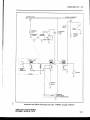
STARTER
swrTcH
ALTERNATOR
OUTPUT
G /P
i
ir
,l
ili
STAFTTER
SOLENOID
\ IA BAT T ER Y
ALIERNATOR
i
L_ _ _ __
souRc€-POWER
R ELAY EN ER G T Z T N
CG
tR C utT
_'_ _ ___!h
I
Alternator and starter schematic(ser. Nos. 7440oal through 744olg2)
AIRPLAI{E AND SYSTEMS
REYISED: JUNE 20.1974
2-tl
CIIEROKEE SIX - 3OO
t^:i
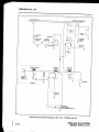
5A
( IN LIN E)
STARTER
swrTcH
WARN
LIGH T
STARTER
SOLENOID
rl
IFF
EXTERNAT
POWER
RECEPTACLE
I
I
_ _ _ _ollrgry3L_
___
:
't,ASTER
swrTcH
:
- - - - -.- - - y'i,_reanaron
f ; ;
r; o\/
\,
\zrz-{.-ol
i
\,'\fff
L_ _ _ _
i
sounce-po
souRcE-powER
__gh R ELAY Eti ER C tZ [{GC | R C U | T
I
Alternator and Starter Schematic(Ser. Nos. 7540001and up)
2-tla
AIRPL{,NE AND SYSTEMS
ISSUED:ruNE 20,1974
CIIEROKEE SIX - 3OO
o
n
o
J>
ul
az
SO
*q
u u.t
FJ
:(o
(o
Yz
oi
t;
l(
O IJJ
!z
oo
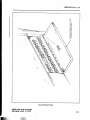
Circuit BreakerPanel
AIRPLANE AND SYSTEMS
REVISED: JULY 17.1975
2-12
CHEROKEESIX - 3OO
VACI,JUMSYSTEM
The vacuum systememployedto operatethe gyro instrumentsincludesan engine-driven
dry vacuumpump, a vacuumregulatorvalve,and the tubingnecessary
to completethe system.
The use of a dry type vacuumpump eliminatesthe needfor an oil-air separatorand the
hardwarenecessaryfor its installation.
The vacuum gaugeis mounted on the right side of the instrumentpanel.The gaugeis
calibrated in inches of mercury and indicates the amount of suction created by the
engine-driven
vacuumpump. As the systernfilter becomescloggedor the lines obstructed,the
gauge will show a decreasein pressure(a low vacuum indicator light is provided in the
annunciatorpanel*). Do not resetthe regulatoruntil the filter and lineshavebeenchecked.
A vacuum regulatorvalve is incorporated in the systemto control vacuumpressureto the
gyro instruments.The regulatorvalveis locatedunder the instrumentpanel.Accessto the valve
for maintenanceand adjustment is gained from below the instrument panel. The regulator
should be set so that the vacuumgaugereads5.0 t .l inchesof mercurywith the enginerunning
at mediumRPM after warm-up.
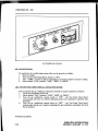
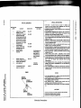
INSTRUMENT PANEL
The instrument panel of the CherokeeSix is designedto accommodatethe customary
advancedflight instrumentsand the normally required power plant instruments.The artificial
horizon and directionalgyro are vacuumoperatedand arelocatedin the centerof the left hand
instrument panel. The vacuum gaugeis located on the right hand instrument panel.The turn
indicator,on the left side,is electricallyoperated.
A natural separationof the flight groupand the powergroup is achievedby the placement
of the flight group in the upper instrumentpaneland the powergroupin the centerand lower
instrument panels.The radios are located in the center section of the panel, and the circuit
breakersarein the lower right behinda decorativedoor.
An annunciator panel* is mounted in the upper instrument panel to warn the pilot of a
possiblemalfunction in the alternator, oil pressure,or vacuumsystems.
rSerialnos.7540001and up
AIRPI.ANE AND SYSTEMS
REVISED: JLJNE20,1974
2-13
b.)
o
I
iE
rd
F
+
o
xFtl
FI
v2
X
(.l)
o
o
a
g
(D
5
FU
5
(D
EE
f>ry
rF
ts1
o>
p3
q>
ez
FU
4vD
{ut
-.{
:.rl
:FI
i3
v. A
I.
2.
3.
4.
5,
6.
7.
8.
9.
IO.
M AST ER SWIT CH
ACCESSORY SWITCHES
ST AL L WARNING L IGHT
RADIO COM PASS
CL OCK
T URN INDICAT OR
AIRSPEED INDT CAT OR
OIRECT IONAL GYRO
ART IF ICT AL HORIZ ON
VERT ICAL
SPEED
INDICAT OR
II. AL T IM ET ER
1 2 , vo R/tts r NDtcAT o R
t3 . vo R/il._ s tNDT CAT OR
I4 . T RANSPONOER
I5 . M ARKER BEACON L IGHT S
I6 . M AGNET IC COM PASS
17.
ll.
I9.
20.
2I.
22.
23.
24.
25,
26.
27.
28.
29.
30.
3I.
32.
A U D IO S E LE C TOR P A N E L
N A v/coM
TR A N S C E TV E R S
A D F R A D IO
oME R A OTO
C IGA R LIGH TE R
A U TOC ON TR OL
E N G]N E IN S T. C LU S TE R
R A D IO C OU P LE R
TR A N S MITTE R S E LE C TOR
P ITC H TR IM S W]TC H
MA GN E TO/S TA R TE R
sw tTcH
MA N IFOLD P R E S S /FU E L FLOW GA U GE
FU E L GA U GE S
TA C H OME TE R
MIC R OP H ON E
TH R OTTLE GIU A D R A N T
33.
3I.
35.
36.
37.
38.
39.
/t0.
41.
42.
43.
FR IC TION LOC K
A IR
A LTE R N A TE
C ON TR OL
R A D IO D IMMIN G LIGH TS
E GT IN D IC A TOR
GY R O S U C TION GA U GE
C IR C U IT B R E A K E R P A N E L
C ON TR OL
C LIMA TE
C E N TE R
C l S C U |T B R E A K E R C OV E R (ON
E A R LY MOD E LS ON LY )
M|X TU R E C ON TR OL LOC K (S E R ,
N os .75i l 000l A N D U P I
A N l .l U N c l A ToR P A N E L (s E R . N os .
7540001 A N O U P )
E N GIN E H OU R ME TE R
CHEROKEESIX - 3OO
PITOT-STATIC SYSTEM
The systemsuppliesboth pitot and static pressurefor the airspeedindicator.altirneterand
verticalspeedindicator(wlten installed).
Pitot and static pressureare picked up by the pitot head on the bottom of the left wing.
An optional heatedpitot head, which alleviatesproblemswith icing or heavy rain, is available.
The switch for pitot heat is locatedon the lower left instrumentpanel.
To prevent bugs and water from entering the pitot antl static pressureholes when tlte
airplape is parked, a cover should be placed over the pitot head. A partially or completely
blocked pitot head will give erratic or zero readingson the instruments'
NOTE
During preflight,checkto makesurethe pitot coveris removed.
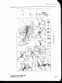
HEATING AND VENTILATING SYSTEM
Heat for the cabin interior and the defroster systemis drawn from a heatermuff attached
to the exhaust system. Controls for these systemsare located on the lower right side of the
instrunrentpanel.
NOTE
If unusual odors are detected, turn off tlre heat and inspect the
system for leaks.
Fresh air inlets are located in the leading edge of each wing at the intersection of thc
tapered and straigfit sections,and in the leadingedgeof the fin. Two largeadjustableoutlets arc
located on each side of the cabin, one forward and one aft of the front seat near the floor.
There are also adjustable outlets above each seat. In airplaneswithout air conditioning. an
optional blower may be added to the overheadvent systemto aid in the circulation of cabin air.
CABIN FEATURES
For ease of entry and exit and for pilot and passengercomflort. the front seats are
adjustable fore and aft. All seats recline and have armrestsand are available with optional
headrests.The front seats can be equipped with optional vertical adjustment. The center and
rear seatsare easily removed for additional cargospace.Some rear seatinstallationsincorporate
lcg retainers with latching mechanismswhich must bc releasedbeforc the rear scats can bc
rentoved.Releasingthe retainersis easilyaccomplishedby turning the latchingmechunisrrrs
90"
with a coin or screwdriver.An optionaljump seat can be installedbetween the two middle seats
to give the airplane a seven-placecapacity.
SingJestrap shoulder harnessescontrolled by inertia reels are standardequipment for thc
front seatsand are offered as optional equipment for the third, fourth, fifth and sixth seats,but
not for the seventhseat.The shoulderstrap is routed over the shoulderadjacentto the windows
and attached to the lap belt in the general area of the person's inboard hip.
AIRPLANE AND SYSTEMS
REVISED:JUNE 20,t974
ii.riiil
iiliilLlillii
2-15
CHEROKEE SIX - 3OO
I
[\
\.__
\
V
5
(F
o
5.9
fiH;
E; H
g.=l - o
tr l a<tl (
l
EEHsT
i&FFF
( ( d >E
Pitot-Static System
NRPI-ANE AND SYSTE}TS
'ISSUED: IULY 12,1973
E
=
EF
vz
E3
UrF
trl >
"
lll
r) v,
{<
=
sH
I.
2.
3.
..
5.
6.
,.
t.
9.
IO.
II.
F RESH AIR INL ET
DRAIN T UBE
OVERHEAD VENT BLOWER
BULKHEADASS€MSLY
OVERHEAO F RESHAIR OU C T
CABIN AIR EXHAUST
F RESHAIROUT L ET
OEFROSTER OUTLST
CABIN HEAT OUT L ET
OEF ROST ER AIR CONTR OL
HEAT ERAIRCONT ROL
I rnes"r,n
ern
I oernosren
)
,,,
----\.
-/ ,,
err
xeereo
-\,/
t
/i
/
/
('
t
(D
D
a.
,
oe
4
B
A
(D
I
F.
D
!'
a
TA
a
o
B
o
It
F
o
xEJ
rd
v,
X
s
{
SEHIAL NOS.7Ai{XII THROUGH 7EOI88
sERIALNos. ?64000lANDuP
''',
I
-)
".
(,
I
CIIEROKEESIX - 3OO
The inertia reel should be checkedby tuggingsharply on the strap. The reel will lock in
place under this test and prevent the strap from extending.Under normal movement,the strap
will extendand retractasrequired.
BAGGAGE AREA
The airplanehas two separatebaggage
areas,eachwith a 100 pound capacity.An 8 cubic
foot forward luggagecompartment,locatedjust aft of the fire wall, is accessiblethrough a l6 x
22 inch door on the right side of the fuselage.A 22 cubic foot aft compartmentis located
behind the fifth and sixth seatsand is convenientlyaccessibleevenduring flight from insidethe
cabin.
NOTE
It is the pilot's responsibility to be sure when the baggageis
loaded that the airplane'sC.G. falls within the allowableC.G.
range.(SeeWeightand BalanceSection.)
STALL WARNING
An approachingstall is indicated by a stall warning indicator which is activated between
five and ten miles per hour abovestall speed.Mild airframe buffeting and gentle pitching may
also precedethe stall. Stall speedsare shown on graphsin the PerformanceChartsSection.The
stall warningindicator is a red warninglight on the left side of the instrumentpanelon earlier
models and a continuoussoundinghom locatedbehind the instrumentpanelon later models.
The stall warningindicatoris activatedby a lift detectorinstalledon the leadingedgeof the lift
wing. During preflight, the stall warningsystemshould be checkedby turning the masterswitch
"ON," lifting the detectorand checkingto deterrnineif the indicatoris actuated.
FINISH
All exterior surfacesare primed with etching primer and finished with acrylic lacquer
availablein a variety of colors and combinations.To keep the finish attractivelooking, economy
sizespray cansof touch-up paint are availablefrom PiperDealers.
AIR CONDTTIONING*
The air conditioning systemis a recirculatingaii system.The major componentsinclude an
evaporator,a condenser,a compressor,a blower, switchesand temperaturecontrols.
The evaporatoris locatedbehind the rear baggagecompartment.This coolsthe air usedfor
the air conditioning system.
The condenseris mounted on a retractablescoop located on the bottom of the fuselage
and to the rear of the baggagecompartmentarea.The scoopextendswhen the air conditioner is
ON and retractsto a flush position when the systemis OFF.
The compressoris mounted on the forward right undenide of the engine.It hasan electric
the compre$pr to the belt drive systemof the
clutch which automatically engagesor disengages
compressor.
rOptional equipment
2.18
NRPI.ANE AI\TDSYSTEMS
REVISED: JANUARY U, 1975
CHEROKEESIX.3OO
An optioncl electric blower is mounted on the aft side of the rear cabin panel.Air from
the baggagearea is drawn through the evaporator by the blower and distributed through an
overheadduct to individualoutletslocatedadjacentto eachoccupant.
The switchesand temperaturecontrol are locatedon the lower right sideof the instrument
panelin the climatecontrol centerpanel.The temperaturecontrol regulatesthe temperatureof
cooling.
decreases
cooling;counterclockwise
the cabin.Turning the control clockwiseincreases
The fan speed switch and the air conditioning ON-OFF switch are inboard of the
temperaturecontrol. The fan can be operatedindependentlyof the air conditioning;however,
the fan must be on for air conditioneroperation.Turning either switch off will disengage
the
door. Coolingair shouldbe felt within one minute
compresso!clutch and retract the condenser
after the air conditioneris turned on.
NOTE
If the systemis not operatingin 5 minutes,turn the systemOFF
until the fault is corrected.
The fan switch alldwsoperationof the fan with the air conditionerturned OFF to aid in
cabin air circulation."LOW," "MED" or "HIGH" canbe selectedto directa flow of air through
the air conditioneroutlets in the overheadduct. Theseoutlets can be adiustedor turned off
individuallly.
The condenserdoor light is locatedto the rieht of the engineinstrument clusterin front of
the pilot. The door light illuminateswhenthe door is openand is off whenthe door is closed.
A circuit breaker on the circuit breaker panel protects the air conditioning electrical
system.
Wheneverthe throttle is in the full forward position, it actuatesa micro switch which
disengages
the compressorand retractsthe scoop.This allowsmaximumpower and maximum
rate of climb. The fan continuesto operateand the air will remaincool for about one minute.
When the throttle is retardedapproximatelyll4 inch, the clutch will engage,the scoopwill
extend, and the systemwill againsupply cool, dry air.
PIPEREXTERNAL POWERI
through
An optional starting installation known asPiperExternal Power(PEP)is accessible
a receptaclelocatedon the left side of the nosesectionaft of the cowling.An externalbattery
can be connectedto the socket,thus allowingthe operatorto crankthe enginewithout having
to gain accessto the airplane'sbattery.
*Optional equipment
AIRPLANE AND SYSTEMS
ISSUED:JULY 12,1973
2-r9
F.A.A.
APPR(lYEll
EMERGE}ICY
PROCEDURES
}ItlilEAPPLICABLE
T(lTHIS
AIRPLA}IE
FLIGHT
AIRPLANE
MANUAL
FO R
CHEROKEE
SIX3OO
THROUGH 32.7640130
APPLICABLE TO SERIAL NUMBERS 32-744OOOI
REPORT:VB-562
MODEL: PA-32-300
;ffi
,
r
l
AIRPLAI{E
FTIGHT
MA}IUAL
Log of Revisions
3-iii
Limitations
3-t
Procedures
3-7
Performance
3-9
Supplements
3-l l
CIIEROKEE SX.3OO
(lFC(I}ITE]ITS
TABLE
Log of Revisions
3-iii
SECTIONI
Limitations
A . E ngine:::::. : . : : . .
B. Fuel
C. Propeller
D. PowerInstruments
E. AirspeedLimitationsandAirspeedInstnrmentMarkings
(CalibratedAirspeed)
F. MaximumWeight
G. C. G. Range
H. Maneuvers
I. Placards
J. RearCabinDoor or RearCabinDoor and CargoDoor Removed.
K. Seven-Pasenger
Operation
L. NoseWheelFairingRemoved
3-l
3-l
3-1
3-l
3-l
3-2
3-2
3-2
3-z
3-3
3-5
3-5
3-5
SECTIONII
Procedures
J -l
SECTIONItr
Performance
3-9
SECTIONIV
OptionalEquipment
A. ElectricPitch Trim Installation
B. AutoFlite tI Installation
C. Air Conditionerlnstallation .
D. PiperAutoControl III and/or AutoControlIIIB lnstallation
E. PiperAltiMatic IIIC Installation
3-l I
3-13
3-16
3-17
3-19
3-23
FAA APPROVEDMAY 14, 1973
REVISED:NOVEMBER6. 1974
REFORT:vB-562PAGE3-i
IiODEL: PA-32-3m
CHEROKEESD(.300
SECTIONI
LIMITATIONS
in the operationof this airplane:
ThefollowingIimitationsmustbeobserved
A.
ENGINE
Lycomins IO'540-KIA5 (Serial nos. 7440001 through 7640A65 and 7640067 through
764007t)
2 andup)
LycomingIO'54GKlG5 (Serialnos.7640066,7640A7
ENGINE LMITS
For all operations2700 RPM,300HP
B. FUEL
100/130minimum aviationgradefuel
c.
PROPELLER
HartzellHC{2YK-l 18475D4or HC{2YK-I( )184754or HC{2YK-I(
Low pitch stop 13.5' t .2o, hieh pitch stop34' I I'
Maximumdiameter80 inches,minimum diameter78.5 inches
)F/F847sD4
OPTIONALPROPELLER(Ser.nos. 7440001through 7540188only)
HartzellHC-C2YK-I( )/8475R{ or HC{2YK-1( )F/F8475R-0
Low pitch stop 12.4' ! .2o, high pitch stop 29' t 1'
Maximum diameter84 inches,minimum diameter82.3 inches
D.
POWERINSTRT'MENTS
OIL TEMPERATURE
GreenArc (Normal OperatingRange)
Red Line (Maximum)
7 5 ' F t o 24 5 "F
245"F
OIL PRESSURE
GreenArc (Normal OperatingRange)
Yellow Arc (Caution Range)
Red Line (Minimum)
Red Line (Maximum)
60 PSIto 90 PSI
25 PSIto 50 PSI
25 PSI
90 PSI
FUEL PRESSURE
GreenArc (NormalOperatingRange)
Red Line (Minimum)
Red Line (Maximum)
Yellow Arc (Idle Range)
l8 PSIto 4'0PSI
I8 PSI
4.0PSI
l2 P S It o 1 8 P S I
TACHOMETER
GreenArc (Normal OperatingRange)
Red Line (MaximumContinuousPower)
FAA APPROVEDMAY 14, 1913
REVISED: FEBRUARY 2. 1976
500 to 2700 RPM
27OORPM
REFORT:vB-562PAGE3-1
MODEL:PA-32-300
CHEROKEESIX.3OO
E.
AIRSPEED LIMITATIONS AND AIRSPEED INSTRUMENT MARKINGS (Calibrated
Airspeed)
NEVER EXCEED
MAXIMUM STRUCTURALCRUISE
MANEUVERTNG
FLAPS EXTENDED
MAXIMUM POSITIVELOAD FACTOR
MAXIMI.JMNEGATIVE LOAD FACTOR
AIRSPEEDINSTRUMENTMARKINGS
Red RadialLine (Never-Exceed)
Yellow Arc (CautionRange)
(SmoothAir Only)
GreenArc (NormalOperatingRange)
WhiteArc (Flap Down)
2I2MPH
I68 MPH
I49 MPH
125MPH
3.8
No inverted maneuversapproved
ZI?MPH (184KTS)
1 6 8MP Ht o 2 1 2M P H
(146KTS to 184KTS)
7l MPHto 168MPH
(62 KTS to 146KTS)
63 MPH to 125MPH
(55 KTS to 109KTS)
34OOLBS
F.
MAXIMUM WEIGIIT
G.
C. G. RANGE
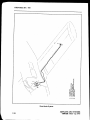
The datum used is 78.4 inchesaheadof the wing leadinsedgeat the intersectionof the
straight and taperedsection.
Weight
(Pounds)
Forward Limit
(In. Aft of Daturn)
RearwardLimit
(In. Aft of Datum)
3400
3300
2904
2400
91.4
89.0
80.0
76.0
95.5
96.2
96.2
96.2
Straight line variation betweenpoints given.
NOTE
It is the responsibility of the airplane owner and the pilot to
insure that the airplane is properly loaded. See Weight and
BalurceSectionfor properloadinginstructions.
H.
MANEIIVERS
No acrobaticmaneuvenincluding spinsapproved.
REPORT:VB-562PAGE3-2
MODEL:PA-32-300
FAA APPROVEDMAY 14,1973
CHEROKEESIX.3OO
r.
PLACARDS
In full view of the pilot:
.THIS AIRPLANE MUST BE OPERATED
AS A NORMAL
CATEGORY AIRPLANE IN COMPLIANCE WITH THE
OPERATING LIMITATIONS STATED IN THE FORM OF
PLACARDS, MARKINGS AND MANUALS. NO ACROBATIC
MANEIIVERS,INCLUDING SPINS,APPROVED.''
..THIS AIRCRAFT APPROVEDFOR NIGHT IFR
NON.ICING
FLrclrT WHEN EQUTPPEDIN ACCORDANCEWITH FAR 9l
oR FA R 135."
In full view of the pilot, the following takeoff and landingchecklistswill be installed:
TAKEOFF CHECKLIST
proper
Mixtureset
Fuel on
tank
Flapsl0' ( lst notch)
pump
Propeller
on
Electricfuel
set
Trim tab - set
Enginegaugeschecked Fastenbelts/harness Controlsfree
Alternateair closed
Doorslatched
Seatbackserect
Air Conditioner- Off
Seatbackserect
Fastenbelts/harness
Air Conditioner- Off
LANDING CHECKLIST
Fuel on propertank
Electricfuel pump on
Mixhrre rich
Propellerset
Flapsdown (125 mph)
The "AIR CONDITIONEROFF" item in the abovetakeoff and
landing check lists is mandatory for air conditioned aircraft only.
On the instrument panelin full view of the pilot:
*ROUGH AIR OR MAI{EUVERING
SPEEDI49 MPH.''
On the instrumentpanelin full view of the pilot:
..DEMONSTRATEDCROSSWIND
COMPONENT20 MPH.''
FAAAPPRO\TEDIT{AY14, I973
REPORT:VB-562PAGE3-3
MODEL:PA-32-300
CHEROKEESIX.3OO
In full view of the pilot: (For operationwith the reardoor removed)
..FOR FLIGHT WITH
THE DOOR REMOVED, SEE THE
LIMITATIONS AND PROCEDURES SECTIONS OF THE
AIRPLANE FLIG}IT MANUAL.'
On the instrumentpanelin full view of the pilot when the AutoFlite is installed:
"FOR HEADING CHANGES: PRESSDISENGAGE SWITCH
ON CONTROL WHEEL. CHANGE HEADING. RELEASE
DISENGAGESW[TCH.''
On the fuel selectorvalve cover:
*ALL WEIGHT IN EXCESS OF 3II2 POUNDS MUST BE
FUEL WEIGHT ONLY. FILL TIP TANKS FIRST.USE MAIN
TANKS FIRST.''
On the instrument panelin full view of the pilot when the AutoFlite II is installed:
.,TURN AUTOFLITE ON. ADJUST TRIM KNOB FOR
MINIMUM HEADING CHANGE: FOR HEADING CHANGE,
PRESS DISENGAGE SWTTCH ON CONTROL WHEEL,
CHANGE ITEADING, RELEASE SWITCH. ROTATE TURN
KNOB FOR TURN COMMANDS. PUSH TURN KNOB IN TO
ENGAGE TRACKER. PUSH TRIM KNOB IN FOR HI
SENSITTVITY. LIMITATIONS AUTOFLITE OFF FOR
TAKEOFF AND LANDING."
On the instrument panel in full view of the pilot when the supplementarywhite strobe
lights areinstalled:
..WARNING . TURN OFF STROBE LIGTITS WHEN TAXIING
IN VICINITY OF OTHER AIRCRAFT, OR DURING FLIGHT
THROUGH CLOUD, FOG OR HAZE."
In full view of the pilot, in the areaof the air conditionercontrolswhen the air conditioner
is installed:
..WARNING- AIR CONDITIONERMUST BE OFF TO INSURE
NORMAL TAKEOFF CLIMB PERFORMAI.ICE."
REPTORT:!fi,-562 PAGE 3'4
MODEL: PA-32-300
FAA APPROVEDMAY 14, T973
REVISED: DECEMBER 15, l97t
CHEROKEESD(.300
J.
REAR CABIN DOOROR REAR CABIN DOORAND CARCODOORREMOVED
The following limitations must be observedin the operationof this airplanewith the rear
cabindoor or rear cabindoor and cargodoor removed:
l.
2.
3.
4.
5.
6.
The airplanemay be flown with the rear cabindoor or rear cabindoor and cargo
door removed.Flight with the front door removedis not approved.
Maximumspeed- 165 mph.
No smoking.
All loosearticlesmust be tied down and stowed.
Jumper'sstaticlinesmust be kept free of pilot's controlsand control surfaces.
OperationapprovedVFR flight conditionsonly.
K. LOADING LIMITATIONS
The followinglimitationsmust be observedin the operationof this airplane.
I
I.
2.
3.
L,
Fill tip tanks first;use main tanksfirst.
This airplanemust not be operatedat grossweightsin excessof 3112 pounds
unlessthe weightover 31 l2 poundsis fuel weightonly.
Remove fuel from the main tanks first when required for proper weight and
balance.
NOSEWHEEL FAIRING REMOVED
When the nose wheel fairing is removed, two nose wheel centeringsprings(part number
67168)must be installed.
M. NOISELEVEL (Ser.nos.7640001andup)
No noise reduction procedures are required for this airplane. The noise level achieved
during type certification was 79.27 d B (A). No determinationhas been made by the
Federal Aviation Adminis.trationthat the noise levels of this airplane are or should be
acceptableor unacceptable
for operationat, into or out of any airport.
FAA APPROVEDMAY I4,I973
REVISED:DECEMBER 15, 1978
REFOIC : VB-562 PAGE 3-5
MODEL: PA-32-30O
CIIEROKEE SD(.300
SECTIONII
PROCEDURES
l.
The stall warningsystemis inoperativewith the masterswitch off.
2.
Electricfuel pump must be on for both landingand takeoff.
3.
Except asnoted above,all operatingprocedures
for this airplanearenormal.
4.
When operating with the rear cabin door removed,it is recommendedthat all
occupantswearparachutes.
5.
Air conditionedModels only: Warning- the air conditionermust be off to insure
n ormal takeoff performance.
6.
Fuel SystemPreflightProcedure:
The fuel systemshould be draineddaily prior to first flight and after refuelingto
avoid the accumulationof water or sediment.Each fuel tank is equippedwith an
individual quick drain locatedat the lower inboardrear cornerof the tank. The fuel
strainerand a systemquick drain valvearelocatedin the fuselageat the lowestpoint
of the fuel system.It is important that the fuel systembe drainedin the following
manner:
a.
Drain each tank through its individual quick drain located at the lower
inboard rear corner of the tank, making sure that enoughfuel has been
drainedto insurethat all water and sedimentis removed.
b.
Placea containerunder the fuel sump drain outlet, which is locatedunder
the fuselage
c.
Drain the fuel strainer by pressingdown on the lever located on the right
hand side of the cabin below the forward edgeof the rear seat.The fuel
selectormust be positionedin the following sequence:off position,left tip,
left main, right main, and right tip while drainingthe strainerto insurethat
the fuel lines betweeneachtank outlet and fuel straineraredrainedaswell
as the strainer.Whenthe fuel tanks are full, it will take approximatelyl1
secondsto drain all the fuel in one of the linesbetweena tip tank and the
fuel strainerand approximatelysix secondsto drain all the fuel in one of
the lines from a main tank to the fuel strainer.Whenthe fuel tanks are less
than full, it will take a few secondslonger.
FAA APPROVEDMAY 14.1973
REFORT: VB-562 PAGE 3-7
MODEL: PA-32-300
SIX.3OO
CTTEROKEE
d.
Exryninethe contentsof the containerplacedunder the fuel sump drain
outlet for waterand sedimentand disposeof the contents.
CAUTION
Whendrainingany amountof fuel, careshouldbe taken to insure
that no fire hazardexistsbeforestartingengine.
After using the under-seatquick drain, it should be checkedfrom outsideto
makesureit hasclosedcompletelyand is not leaking.
REFORT:vB-562PAGE3{
MODEL:PA-32-300
FAA APPROVEDMAY 14, 1973
CREROKEESIX.3OO
SECTION Itr
PERFORMAI{CE
AII performanceis givenfor a weight of 3400 pounds.
Loss of altitude during stallscan be as great as 350 feet, dependingon configurationand
power.
Stallingspeed,in mph, (CalibratedAinpeed):
FlapsUp
- 7l
FlapsDown - 63
Flap deflectionversushandlepositionis:
lst notch - l0 degrees
2nd notch - 25 degrees
3rd notch - 40 deerees
Air ConditionedModelsOnly:
When the full throttle position is not used or in the event of a malfunctionwhich
causesthe compressorto operateand the condenserdoor to remainextended.a decrease
in
rate of climb of asmuch as 100 fpm canbe expectedat all altitudes.
FAA APPROVEDMAY 14. 1973
REFORT: VB-562 PAGE 3,9
MODEL: PA-32-300
CHEROKEESD(.300
SECTIONry
OPTIONAL EQUIPMENT
NOTE
THE INFORMATION CONTAINED IN THIS SECTION
APPLIESWHEN THE RELATED EQUIPMENTIS INSTALLED
IN THE AIRCRAFT.
A.
Electric Pitch Trim Installation
B.
AutoFlite II Installation
C.
Air ConditionerInstallation
D.
Piper AutoControl III and/or AutoContol IIIB Installation
E.
Piper AltiMatic IIIC Installation
FAA APPROVEDMAY 14,1973
REWSED: NOVEMBER6, I 974
REFORT:vB-562 PAGE3-ll
MODEL: PA-32"-300
CIIEROKEE SD(-3OO
A.
ELECTRrc PITCH TRIM INSTALLATION
The following emergency information applies in case of electric pitch trim
malfunction.
l.
electricpitch trim by operatingpush button
In caseof malfunction,disengage
panel.
trim switch on instrument
2.
In emergenry,electric pitch trim may be overpoweredusingmanualpitch trim.
3.
In cruise configuration,malfunction results in 10" pitch changeand 50 ft
altitudevariation.
FAA APPROVED
MAY 14, 1973
REPORT:VB-562PAGE3-13
MODEL:PA-32-300
CHEROKEESIX.3OO
D.
PIPER AUTOCONTROL Itr AI{D/OR AUTOCONTROL IIIB INSTALLATION
l.
LIMITATIONS
a. Autopilot OFF duringtakeoff and landing.
b. Autopilot useprohibitedabove180 MPH CAS.
1
PROCEDURES
a. PREFLIGHT
( l) Roll Section
(a) Place Radio Coupler in "Heading" mode and place A/P
ON/OFF switch in the "ON" positionto engageroll section.
Rotate roll command knob Left and Right and observe
conbol wheel describesa correspondingLeft and Right
turn, then centerknob.
(b) Set proper'D.G.Headingon D.G. and tum HeadingIndice
to aircraft heading.Engage"Heading" mode switch and
rotate HeadingIndice right and left. Aircraft control wheel
should turn samedirection as Indice. While D.G. indice is
set for a left turn, grasp control wheel and override the
servo to the right. Repeatin oppositedirection for right
turn.
(c) If VOR signalavailablecheckOmni modeon RadioCoupler
by swingingOmni needleleft and rieht slowly.Observethat
control wheelrotatesin directionof needlemovefrent.
(d) Disengage
by placingthe AIP ON/OFF switchto the "OFF"
position.
b.
IN-FLIGHT
( I ) Trim airplane(ball centered).
(2) Check air pressureor vacuumto ascertainthat the DirectionalGyro
and Attitude Gyro arereceivingsufficientair.
(3) Roll section
en6age,center Roil command Knob, prace the Alp
ON/OFF switch to the .'ON" position.To turn rotate roll
command knob in desired direction. (Maximum angle of
bank shouldnot exceed30".)
(b) For headingmode, set DirectionalGyro with Magnetic
Compass.Push dircctionalgyro HDG knob in, rotate to
aircraft heading.Placethe consoleHDG ON/OFF switch to
the "ON" position. To selecta new aircraft heading,push
D.G. headingknob IN and rotate, in desireddirection of
turn, to the desiredheading.
NOTE
In HDG mode the maximum bank angles are limited to
approximately2Oo and singlecommand,headingchangesshould
be limited to 150o. (HDG Indice not more than 150" from
actual aircraftheading.)
FAA APPROVEDJUNE 20,1974
REVISED: NOVEMBER6. 1974
REPORT:VB-562PAGE3-19
MODEL: PA-32-300
CHEROKEESIX.3OO
(4) voR
(a) To Intercept:
l. Using OMNI Bearing Selector,dial desiredcourse,
inboundor outbound.
2. Setidenticalheadingon CourseSelectorD.G.
3. After aircraft has stabilized,position coupler mode
selector knob to OMNI mode. As aircraft nears
selectedradial, interception and crosswindcorrection
will be automatically accomplishedwithout further
switching.
NOTE
If aircraft position is lessthan 45o from selectedradial, aircraft
will intercept before station. If position is more than 45 ",
interceptionwill occur after station passage.
As the aircraftnears
the OMNI station,(l/2 mile) the zoneof confusionwill direct an
"S" turn in alternatedirectionsas the OMNI indicator needle
swings.This alternatebankinglimited to the sturdardD.G. bank
angle,is an indicationof stationpassage.
(b) To selectnew course:
l. To selecta new courseor radial,rotatethe HDG indice
to the desiredHDG (match course).
2. Rotate OBS to the new course. Aircraft will
automatically turn to the intercept headingfor the
new course,
(c) To changestations:
I. If samecourseis desired,merely tune receiverto new
stationfrequency.
2. If different courseis desired,position coupler mode
selectorto HDG mode. Dial courseselectorD.G. to
new course. Dial OBS to new course and , position
couplermodeselectorto OMNI mode.
(5) VOR Approach
Track inbound to stationasdescribedin VOR navigationsection.
After stationpassage:
(a) Dial outbound courseon CourseSelectorD.G., then dial
samecourseon OBS.
(b) After establishedon outbound radial, position coupler
mode selectorto HDG mode and selectoutboundprocedure
turn heading.After 40 secondsto I minute selecta turn in
the desireddirection with the CourseSelectorD.G. to the
(c)
3t:"d;$
iiT;1if.':nl::o-'
(d) When aircraft heading is 45 o to the inbound course, dial
andposition
course
HlS".
:"'J;n,iitii'31"3;?;.'3-,t?
REPORT:VB-562PAGE 3-20
MODEL: PA-32-300
FAA APPROVEDJUNE 20,1974
CHEROKEESIX. 3OO
NOTE
For precise tracking over OMNI station, without "S" tum,
position coupler mode selector to HDG mode just prior to
station passage.If holding pattern is desired,position coupler
mode selector to HDG mode at station passageinbound and
selectoutbound headingin directionof turn. After elapsedtime,
dial inbound course on Course Selector D.G. When aircraft
headingis 45o to radial,positioncouplermodeselectorto OMNI
mode.
(6) LOC ApproachOnly
(a) To intercept dial ILS outbound courseon CourseSelector
D.G. When stabilized,position coupler mode selectorto
LOC REV mode.
(b) After interceptionand whenbeyondouter marker,position
coupler mode selector to HDG mode and dial outbound
procedureturn heading.After one minute, dial inbound
procedureturn headingin directionof turn.
(c) When aircraft headingis 45 o to ILS inbound coursedial
inbound course on Course Selector D.G. and position
couplermodeselectorto LOC NORM mode.
(d) At the missedapproachpoint (M.A.P.), or when missed
approachis elected,positioncouplermodeselectorto HDG
modeand executemissedapproaehprocedure.
(7) LOC Approach- BackCourse(Reverse)
(a)l:"Ii"ff
i.:,:'lJ:d',ff
5"'iliii,itl'?:1fl
,ff':'lf,[x
modeselectorto LOC NORM mode.
(b) After interceptionand when beyond fix, position coupler
mode selectorto HDG and dial outbound procedureturn
ffl$ifft'ililff
#trf,
procedure
diarinbound
turn
(c)HA*::'1",i,ifi
;:#:::11,::,:T?.1,'$#3:::'.
to LOC REV mode.
(d) Approximately l/2 mile from runway, position coupler
modeselectorto HDG mode to prevent"S" turn ovel ILS
stationnearrunway threshold
(e) Missedapproach- sameasFront Course.(See(6) d)
FAA APPRO\{EDJUNE 2A.
'974
irliiiiiiiiiiliiiililiLiiLLiiiiliiiiii
rr
REPORT: YF562 PAGE $2t
MODEL: PA-3?-300
CIIEROKEESIX.3OO
C.
3.
EMERGENCYOPERATION
( I ) In an emergencythe AutoControl can be disconnected
by placingthe
A/P ON/OFF switchto the "OFF" position.
(2) The AutoControl can be overpoweredat either control wheel.
(3) An Autopilot runaway, with a 3 seconddelay in the initiation of
recovery,wfule operatingin a climb, cruiseor descending
flight could
resultin a 38" bank and 40 foot altitudeloss.
(4) An Autopilot runaway, with a I seconddelay in the initiation of
recovery,during an approachoperation,coupledor uncoupled,could
resultin an 8o bank and l0 foot altitudelois.
PERFORMANCE
No change.
REFTORT:
V8-562 PAGE 3-ZZ
MODEL: PA-32-300
20.1974
FAA APPROVED
. RIVISED: NOVEMBER
'IJIYE 6, 1974
PR0CEIIURES
EtrlERGEllCY
Introduction
EnginePower LossDuring Takeoff
EnginePowerLossIn Flight
PowerOff Landing . . .
PropellerOverspeed
Spins .
OpenDoor
Fire
Lossof Oil Pressure
Lossof Fuel Pressure
High Oil Temperature
Alternate Failure
EngineRoughness
4-l
4-l
+2
+3
4-3
4-4
+4
+5
4-6
+6
+6
+7
+7
SD(.300
CAEROKEE
EMER,GENCYPROCEDURES
INTRODUCTION
This sectioncontainsproceduresthat are recomrnended
if an emergencyconditionshould
occur during ground operation, takeoff, or in flight. Theseproceduresare zuggested
as the best
courseof action for coping with the particular condition described,but are not a substitutefor
soundjudgmentand commonsense.Sinceemergencies
rarely happenin modernaircraft,their
occuren@ is usuallyunexpected,and the best correctiveaction may not'alwaysbe obvious.
Pilots should familiarize themselveswith the proceduresgivenin this sectionand be preparedto
take appropriateaction should an emergencyarise.
Most basic emergencyprocedures,such as power off landings,are a normal part of piiot
training. Althoueh these emergenciesare discussedhere, this information is not intended to
replace such training, but only to provide a source of referenceand review, and to provide
information on procedureswhich are not the samefor all aircraft. It is suggested
that the pilot
reviewstandardemergencyproceduresperiodicallyto remainproficient in them.
ENGINE POWERLOSS DI]RING TAKEOFF
The proper action to be taken if loss of power occun during takeoff will dependon
circumstances.
t. If sufficient runway remainsfor a normal landing,land straightahead.
2. If insufficient runway remains,maintain a safeairspeedand make only a shallowturn
if necessaryto avoid obstructions.Use of flaps dependson circumstances.
Normally,
flapsshouldbe fully extendedfor touchdown.
3. If you havegainedsufficient altitude to attempt a restart,proceedas follows:
a. MAINTAIN SAFEAIRSPEED
b. FUEL SELECTOR. SWITCHTO ANOTI{ER TANK CONTAINING FUEL
c. ELECTRICFIJEL PIrMP - CHECKON
d. MIXTURE . CHECK RICH
e. ALTERNATE AIR - ON
NOTE
'
If enginefailure wascausedby fuel exhaustion,power will not be
regainedafter tanks are switcheduntil empty fuel linesare filled,
which may requireup to ten seconds.
If power is not regained,proceedwith the POWEROFF LANDING procedure.
EMERGENCY PROCEDURES
ISSLJED:
JULY 12,1973
+l
CHEROKEESIX . 3OO
ENGINE POWERI,oSS IN FIIGHT
Completeenginepower los is usually causedby fuel flow intemrption, and power will be
restoredshortly after fuel flow is restored.If power loss occursat low altitude, the first step is
to preparefor an emergencylanding(SeePOWEROFF LANDING). Maintainan airspeedof at
least100 MPH IAS, and if altitudepermits,proceedasfollows:
l. Fuel Selector- Switchto anothertank containingfuel.
2. Electric Fuel hrmp - On
3. Mixture - Rich
4. AlternateAir - On
5. EngineGauges- Checkfor an indication of the causeof power loss.
6. If no fuel pressureis indicated, check tank selectorposition to be sureit is on a tank
containingfuel.
Whenpoweris restored:
8. AltemateAir - Off
9. ElectricFuel hrmp - Off
If the abovestepsdo not restorepower, preparefor an emergencylanding.
If time permits:
l.
Ignition Switch- "L" then "R" then back to "BOTH."
2. Throttle and Mixture - Different settings.(This may restore power if the problem is
too rich or too lean a mixture, or if there is partial fuel rystem restriction.)
3. Try other fuel tanks. (Waterin the fuel could take some time to be usedup, and
allowing the engineto windmill may restorepower. If power lossis due to water, fuel
pressureindicationswill be normal.)
NO13
If enginefailure wascausedby fuel exhaustion,power will not be
regainedafter tanks are switcheduntil empty fuel lines are filled,
which may require up to ten seconds.
If poweris not restored,proceedwith POWEROFF LANDING procedure.
+2
EMERGENCYPROCEDURES
ISSUED:JULY 12,1973
CHEROKEESIX - 3OO
POWEROFF LANDING
If lossof power occursat altitude, trim the aircraft for bestgliding angle(100 MPH IAS,
Air Cond. - OFF), and look for a suitablefield. If measurestaken to restorepower are not
effective,and if time permits,checkyour chartsfor airportsin the immediatevicinity;it may be
possibleto land at one if you have sufficient altitude. At best gliding angle,with the engine
windmilling and the propeller control in full "DECREASE RPM," the airplane will travel
approximatelyone and one half milesfor eachone thousandfeet of altitude.If possible,notify
is aboard,let
the FAA by radio of your difficulty and intentions.If anotherpilot or passenger
themhelp.
Whenyou havelocateda suitablefield, establisha spiralpattern around this field. Try to
be at 1000 feet abovethe field at the downwindpositionto makea normal approach.Whenthe
field can easilybe reached,slow up to 90 MPH IAS for the shortestlanding.Excessaltitudemay
be lost by wideningyour pattern,usingflapsor slipping,or a combinationof these.
Touchdownshouldnormally be madeat the lowestpossibleairspeed,with full flaps.
Whencommittedto landing:
l.
Ignition- Off
2. MasterSwitch- Off
3. Fuel Selector- Off
4. Mixture - Idle Cut0ff
5. SeatBelt (and harnessif available)- Tight
PROPELLERO\IERSPEED
Propeller overspeedis causedby a malfunction in the propeller governor,or low oil
pressure,which allows the propeller bladesto rotate to full low pitch. If this shouldoccur,
proceedas follows:
I. THROTTLE-RETARD
2. OIL PRESSURE.CHECK
3. PROPELLERCONTROL- FULL DECREASERPM.THEN SET IF A}.IY CONTROL
IS AVAILABLE.
4. REDUCEAIRSPEED
s. THROTTLE - AS REQUIREDTO REMAIN BELOW2700 RpM.
EMERGECf.IYPROCEDURES
ISSUED:JULY 12,1973
CHEROKEE
SIX.3OO
SPINS
Intentional spins are prohibited in this aircraft. If a spin is inadvertently entered,
immediatelyusethe following recoveryprocedures:
I. THROTTLE. IDLE
2. RUDDER . FULL OPPOSITETO DIRECTIONOF ROTATION
3. CONTROLWHEEL. FULL FORWARD
4. RUDDER. NEUTRAL (WHEN ROTATION STOPS)
5. CONTROL WHEEL - AS REQUTREDTO SMOOTHLYREGATNLEVEL FLrcH'r
ATTITUDE
OPENDOOR
The cabin door on the Cherokeeis double latched,so the chancesof its springingopenin
flight at both the top and bottom are remote.However,shouldyou forget the upperlatch, or
not fully engagethe lower latch, the door may springpartially open.This will usuallyhappenat
takeoff or soon afterward.A partially open door will not affect normal flight characteristics,
and a normallandingcanbe madewith the door open.
'i If both upper and lower latchesare open, the dooi will trail slightly open, and airspeedwill
be reducedslightly.
:; To closethe door in flight, proceedasfollows:
l.
Slowairqaft to 100MPH lAS.
2. CabinVents- Close
3. StorrnWindow- Open
4. If upper latch is open - latch. If lower latch is open - open top latch, push door
further open,and then closerapidly. Latch top latch.
A slip in the directionof the open.doorwill assistin latchingprocedure.
H
EMERGENCYPROCEDURES
ISSUED:JULY 12,1973
CHEROKEESIX.3OO
FIRE
The presenceof fire is noted through smoke,smell,and heat in the cabin.It is essential
that the sourceof the fire be promptly identified through instrument readings,characterof the
smoke,or other indications,sincethe action to be takendifferssomewhatin eachcase.
SOURCEOF FIRE . CHECK
t.
ElectricalFire (Smokein Cabin):
a. MasterSwitch- Off
b. Vents - Open
c. CabinHeat- Off
d. Land assoonaspossible.
)
EngineFhe (In Flight):
a. Fuel Selector- Off
b. Throttle - Closed
c. Mixture - Idle Cut0ff
d. Heater- Off (In all casesof fire)
e. Defroster- Off (In all casesof fire)
If terrainpermits,land immediat6ly.
f.
NOTE
The possibility of an engine fue in fli&t is extremely remote.
The proceduregivenaboveis generaland pilot judgment should
be the decidingfactor for action in suchan emergency.
3.
EngineFire (During Start):
Engine fres during start are usually the result of overpriming. The following
procedureis designedto draw the excessfuel back into the induction system.
a. If enginehasnot started:
(l) Mixture-Idle CutOff
(2) Throtfle - Open
(3) Turn engine with starter (This is an attempt to pull the fre into the
engine.)
b. If enginehasalreadystartedand is running, continue operatingto try pulling the
fire into the engine.
c. In either casestated in (a) and (b), if the fire continueslonger than a few
seconds,the fire should be extinguishedby the best availableexternalmeans.
d. If external fire extinguishingis to be applied:
( I ) Fuel SelectorValves- Off
(2) Mixture - Idle CutOff
EMERGENgY PROCEDURES
ISSLJED:JULY 12,1973
4-5
CHEROKEESIX - 3OO
LOSSOF OIL PRESSURE
Loss of oil pressuremay be eitherpartial or complete.A partiallossof oil pressureusually
indicatesa malfunction in the oil pressureregulatingsystem,and a landing should be made as
soon aspossibleto investigatethe causeand preventenginedamage.
A complete loss of oil pressureindication may signify oil exhaustionor may be the result
of a faulty gauge.In either case,proceed toward the nearestairport, and be preparedfor a
forced landing. If the problem is not a pressuregauge malfunction, the engine may stop
zuddenly.Maintain altitude until zuch time as a deadstick landingcanbe accomplished.
Don't
changepowersettingsunnecessarily,
asthis may hastencompletepower loss.
Dependingon the circumstances,it may be advisableto make an off airport landingwhile
power is still available,particularly if other indications of actual oil pressureloss,suchassudden
in temperatures,
increases
or oil smoke,areapparent,and an airport is not close.
If enginestoppageoccurs,proceedto POWEROFF LANDING.
LOSSOF FUEL PRESSURE
i.
,;
l.
2.
ElectricBoostPump- On
Fuel Selector- Checkon full tank
If problem is not an empty fuel tank, land assoon aspracticaland haveengine-drivenfuel
pump checked.
HIGH OIL TEMPERATURE
An abnormaly high oil temperature indication may be causedby a low oil level, an
obstruction in the oil cooler, damagedor improper baffle seals,a defectivegauge,or other
causes.Land assoon as practicalat an appropriateairport and havethe causeinvestigated
A steady,rapid rise in oil temperatureis a signof trouble. Land at the nearestairport and
let a mechanicinvestigatethe problem. Watch the oil pressuregaugefor an accompanyingloss
of preszure.
6
EMERGENCY PROCEDURES
ISSUED:ruLY 12,1973
CHEROKEESIX - 3OO
ALTERNATOR FAILURE
Loss of alternator output is detected through zero reading on the ammeter. Before
executing the fotlowing procedure, insure that the reading is zero and not merely low by
actuating an electrically powered device, such as the landing light. If no increasein the ammeter
reading is noted, alternator failure can be assumed.
ReduceElectrical Load.
,, l.
2. Alternator Circuit Breakers- Check
"Alt" Switch - Off (for I second), then On
3.
If the ammeter continues to indicate no output, or alternator will not stay reset,turn off
"Alt" switch, maintain minimum electricalload and land as soon as practical.All electricalload
is being suppliedby the battery'
ENGINE ROUGHNESS
Engineroughness
may be causedby dirt in the injectornozzles,inductionsystemicing,or
proceedasfollows:
ignition problems.To eliminateroughness,
l.
Mixture - Adjust for maximum smoothness.Enginewill run rough if too rich or too
Iean.
2. AlternateAir - On
3. ElectricFuel Pump- On
4. Fuel Selector- Changetanks to seeif fuel contaminationis the problem.
5. Engine Gauges- Check for abnormalreadings.If any gaugereadingsare abnormal,
proceedaccordingly.
6, MagnetoSwitch- "L" then "R," then back to "BOTH." If opcrationis satisfactory
on eithermagneto,proceedon that magnetoat reducedpower,with mixturefull rich,
to a laudingat the frst availableairportpreparefor a precautionary
persists,
If roughness
landingat pilot'sdiscretion.
EMERGENCYPROCEDURES
REVISED: JANUARY ll, 1974
4-7
AND
BALANCE
WEIGHT
FO R
stx300
CHEROKEE
APPLICABLE TO SERIAL NUMBERS 32-744OOOI
THROUGH 32-7640130
ISSUED:MAY 14, 1973
REYISED:'MARCH 23. 1979
REPORT:VB-551
MODEL: PA-32-300
WEIGHT
AIIDBAIA}ICE
Log of Revisions
5-iii
Weight and Balance
5-l
Weight and BalanceData - Weighing Procedure
5-3
Weight and BalanceData
5-7
C. G. Range and Weight Instructions
5-8
CHEROKEESIX.3OO
WEIGHT AND BALANCE
In order to achievethe performance,safety and good flying characteristicswhich are
designedinto the airplane,it must be flown with the weiglrt and center of gravity (C.G.)
position wthin the approvedenvelope.The aircraft offers a tremendousflexibility of loading.
full fuel
However,you cannot fill the airplane,with the maximum numberof adult passengers,
With the flexibility comesresponsibility.The pilot must ensure
tanks and maximum baggage.
that the airplaneis loadedwithin the loadingenvelopebeforehe makesa takeoff.
for any aircraft. An overloadedairplanewill not take off,
Misloadingcarriesconsequences
climb or cruise as well as a properly loaded one. The heavierthe airplaneis loaded,the less
climb perfornanceit will have.
If the C.G. is too far
Center of gravity is a determiningfactor in flight characteristics.
forward in any airplane,it may be difficult to rotate for takeoff or landing.If the C.G. is too far
aft, the airplane may rotate prematurely on takeoff or try to pitch up during climb.
Longitudinal stability will be reduced.This can lead to inadvertentstallsand evenspins;and
spinrecoverybecomesmore difficult as the centerof gravitymovesaft of the approvedlimit.
A properly loadedaircraft, however,will perform asintended.This airplaneis designedto
'
provide excellent performanceand safety within the flight envelope.Before the airplaneis
delivered,it is weighed,and a basicweight and C.G. locationis computed.(Basicweight consists
of the empty weight of the aircraftplus the unusablefuel and full oil capacity.)Usingthe basic
weight and C.G. location, the pilot can easilydeterminethe weight and C.G. position for the
loadedairplaneby computingthe total weightand momentand then determiningwhetherthey
arewithin the approvedenvelope.
The basicweight and C.G. location for a phrticularairplanearerecordedin the aircraftlog
book or in the weight and balancesectionof the Airplane Flight Manual.The current values
shouldalwaysbe used.Whenevernew equipmentis addedor any modificationwork is done,the
mechanicresponsiblefor the work is requiredto computea new basicweight and basicC.G.
position and to write thesein the aircraftlog book. The owner shouldmakesurethat it is done.
A weight and balancecalculationcan be helpful in determininghow much fuel or baggage
to removesome
can be boardedso as to keep the C.G. within allowablelimits. If it is necessary
gross
pilot
to
within
allowable
not
hesitateto do
of the fuel
maximum
weight, the
should
stay
so.
The following pagesare forms usedin weighingan airplanein productionand in computing
basic weight, basicC.G. position, and useful load. Note that the useful load includesfuel, oil,
Following this is the method for computingtakeoff weightand
baggage,cargoand passengers.
c.G.
ISSUED:MAY 14,1973
REPTORT:
VB-551PAGE 5-l
MODEL: PA-32-300
CHEROKEESIX.3OO
WEIGIIT AND BALANCE DATA
WEIGIIING PROCEDURE
At the time of delivery,PiperAircraft Corporationprovideseachairplanewith the licensed
empty weight and center of gravity location. This datais on Page5-7.
The removal or addition of an excessiveamount of equipment or excessiveairplane
modificationscan affect the licensedempty weight and empty weight centerof gravity.The
following is a weighingprocedurcto determinethis licensedempty weightand centerof gravity
location:
I.
PREPARATION
a.
Be certainthat all itemscheckedin the airplaneequipmentlist areinstalled
in the properlocationin the airplane.
b.
Removeexcessive
dirt, grease,moisture,foreignitemssuchasragsand tools
from the airplanebefore weighing.
Defuel airplane.Then openall fuel drainsuntil all remainingfuel is drained.
Operateengineon each tank until all undrainablefuel is used and engine
stops.
2.
d.
Drain all oil from the engine,by meansof the oil drain, with the airplanein
ground attitude. This will leave the undrainableoil still in the system.
Engine oil temperatureshould be in the normal operatingrangebefore
draining.
e,
Placepilot and copilot seatsin fourth (4th) notch, aft of forwardposition.
Put flaps in the fully retracted position and all control surfacesin the
neutral position.Tow bar strouldbe in the properlocationand all entrance
and baggage
doorsclosed.
f.
Weieh the airplane inside a closed building to prevent errors in scale
readingsdue to wind.
LEVELING
a.
With airplaneon scales,block main gearoleo pistonsin the fully extended
position.
b.
Level airplane(seediagram)deflatingnosewheel tire, to centerbubbleon
level.
ISSLJED:
MAY 14,1973
REPTORT:
VB-551 PAGE 5-3
MODEL: PA-32.30O
CHEROKEESD(.300
3.
WEIGHING. AIRPLANE EMPry WETGHT
a'
lVith the ailplane level and brakes released,record the weight shown on
each scale.Deduct the tare, if any, from each reading.
ScalePositionand Symbol
Nose\Yheel
(N)
Right'Main.Wheel
(R)"
Left Main Wheel
(L)
Airplane Empty Weight,asWeighed(T)
4.
EMPTYWEIGHTCENTEROF GRAVITY
a.
The following geometry appliesto the PA-32-300airplanewhen airplaneis
level(SeeItem 2).
24il
i illl
{t
#'
-,-q6r.
LevelPoints
(FuselageLeft Side)
I
I
Wing Leading Edge
t,
R+ L
AS=
The datum is 78.4 inchesahead
of the wing leadingedgeat the
intersectionof the straightand
taperedsection.
i
REFORT: VB-551 PAGE 5,f
MODEL: PA-32-3O0
ISSUED:II{AY 14, 1973
CHEROKEESD(.300
b.
Obtain measurement"A" by measuringfrom a plumb bob droppedfrom
the wing leading edge, at the intersectionof the straieht and tapered
section, horizontally and parallel to the airplane centerline, to the main
wheelcenterline.
Obtain measurement'oB" by measuringthe distancefrom the main wheel
centerline,horizontallyand parallelto the airplanecenterline,to eachside
the measurements.
of the nosewheelaxle.Then average
d.
The empty weight center of gravity (as weighed including optional
equipment and undrainable oil) can be determined by the following
formula:
c.G. A rm = 7 8 . 4+ A -B (N)
T
C. G. Arm = 78.4+ (
5.
inches
)-(
LICENSEDEMPTYWEIGHTAND EMPTYWEIGHTCENTEROF GRAVITY
Weight
Arm
Moment
Empty Weight(asweighed)
UnusableFuel (.4 gallon)
+ 2.3
103.0
+237
LicensedEmpty Weight
:iri
fti;
ISSLJED:MAY 14,1973
REVISED: NOVEMBER6. 1974
REPTORT:
VB-551 PAGE 5-5
MODEL: PA-32.30O
CHEROKEESIX.3OO
WEIGIIT AND BALANCE DATA
MODEL PA-32.300CHEROKEE
AirplaneSerialNumber
RegistrationNumber
Date
AIRPLANE BASTCWEIGHT
Weight
(Lbs)
Item
C. G. Arm
(InchesAft
of Datum)
X
Moment
(In-Lbs)
Actual
Computed
*Empty Weight
UnusableFuel (3.2 pints)
2.3
103.0
237
22.5
r6.6
374
StandardEmpty Weight
OptionalEquipment
LicensedEmpty Weight
Oil ( 12 quarts)
BasicWeight
*Empty weight is defined as dry empty weight (including paint and hydraulic fluid) plus
2.4lbs undrainableengineoil.
AIRPLANE USEFUL LOAD - NORMAL CATEGORYOPERATION
(GrossWeight)- (LicensedEmpty Weieht)= UsefulLoad
(3400lbs)
(
lbs)
=
lbs.
THIS LICENSED EMPfY WEIGHT, C. G. AND USEFUL LOAD ARE FOR THE
AIRPLANE AS DELIVERED FROM THE FACTORY. REFER TO APPROPRI"ATE
AIRCRAFT RECORDWHENALTERATIONS HAVE BEEN MADE.
ISSUED:MAY 14, 1973
REVISED:JAIYUARY I l. 1974
REPORT:VB-551PAGE 5-7
MODEL: PA-32-3OO
CHEROKEESIX.3OO
C. G. RANGE AND WEIGHT INSTRUCTIONS
l.
Add the weightof all itemsto be loadedto the basicweight.
2.
Use the loadinggraphto determinethe moment of all items to be carriedin the airplane.
3.
Add the momentof all itemsto be loadedto the basicweightmoment.
4.
Divide the total moment.bythe total weightto determinethe C.G,-location-;
5.
By using the figuresof ltem I and Item 4, locate a point on the C.G. rangeand weight
graph.tf the point falls within the C.G. envelope,the loadingmeetsthe weightand balance
requirements.
SAMPLELOADING PROBLEM(NormalCategory)
Weight
(Lbs)
Arm Aft
Datum
(Inches)
Moment
(In-Lbs)
Pilot and Front Passenger
340.0
85.5
29074
(CenterSeats)
Passengers
340.0
I l8 . l
40t54
(RearSeats)
Passensers
340.0
155.7
52938
ii Basic Weight
(Jump Seat)+
Passenger
I18.1
Fuel (84-GallonMaximum)
95.0
(Forward)
Baggage
42.0
(Aft)
Baggage
178.7
Total LoadedAirplane
inches aft of the
The center of gravity (C.G.) of this sampleloadingproblemis at
datum line. Locate this point (
) on the C.G. rangeand weight graph. Since this point
falls within the weiglrt- C.G.envelope,this loadingmeetsthe weightand balancerequirements.
IT IS THE RESPONSIBILITYOF THE PILOT AND AIRCRAFT OWNERTO INSURE
THAT THE AIRPLANE IS LOADED PROPERLY.
*Optional Equipment.
vB-ssl PAGEs€
REPORT:
MODEL:PA-32-300
q
fll
ISSLJED:
MAY 14. 1973
REVISED: JAhIUARY ll, 1974
EHEROKEESD(.300
LOADINGGRAPH
..c\)
D(
."l
o+
-19\
\e,2
t f)
,.4i
ad
450
-t
^1Q
<i.)
4m
/
u,
o
z
/
f. :
O:. 350
o-
/
F,j
(9
300
3
o
o
60
-'
ul
mo
s
d
150
100
/
0
/
/
's'-
{{o
50
/,
I
/
,/
,/
Fl
Iscefqu-
7,
,t .1
'/
44
v
m ? F , Cr3 5 t t o
50
MOMENT/I MO (POUNDS.INCHES}
ISSIJED:[tAY 14,1973
REFOR.T:VB-551 PAGE 5-9
IiODEL: PA-32-30o
CHEROIGE SIX.3OO
C. G . RA NG EA ND WE I G HT
3400
\
3(x)0
/
/
::.
8'u '2 ffi
Z rl
I
oi
c
=
:':
/
F
T
(9
E zzoo
=
1800
1400
r8 0
828/.868890
96
INCHESAFT OF DATUM
REFORT:VB-551PAGE5-10
MODEL:PA-32-30O
ISSI,IED:MAY 14, 1973
(lPE
RATI}IG
I}ISTRU
CTI(I}I
S
Preflight
Starting Engine
Starting EngineWhenCold
Starting EngineWhenHot .
StartingEngineWhenFlooded
StartingWith ExtemalPowerSource
Warm-Up
GroundCheck
Takeoff
Climb
Stalls .
Cruising
Turbulent Air Operation
Maneuvers
Approachand Landing . .
StoppingEngine
Air sp eedData.
Mooring
Weightand Balance
Air Conditioning
Air ConditionerOperationalCheckProcedure
Air ConditionerEffectson AirplanePerformance
EmergencyLocatorTransmitter
7-l
7-2
7'2
'l'3
7-3
7'3
/ -f
7-6
7-6
7-6
7-8
7-8
7-8
7-9
7-9
7'9
7-9
7-10
7-10
7-l I
7-ll
l -l
CHEROKEESIX - 3OO
OPERATING IN STRUCTIONS
PREFLIGHT
The airplane should be given a thorough preflight and walk-aroundinspection.The
preflight shouldinclude a checkof the airplane'soperationalstatus,computationof weightand
C.G. limits, takeoff distance,and in flight performance.A weatherbriefingshouldbe obtained
for the intended fliglrt path, and any other factors relatingto a safeflight should be checked
beforetakeoff.
Walk-AroundInspection
I.
a. Releaseseatbeltssecuringthe control wheel.
b. MasterswitchON.
c. Checkfuel quantity gauges(four tanks).
d. Masterswitchand ignitionOFF.
2. a. Check for external damageand operationalinterferenceof control surfacesor
hinges.
b. Insurethat wingsand control surfacesare free of snow,ice or frost.
3. a. Visually checkwing tip tank fuel supply;securecaps.
b. Drain wing tip tank sumps(SeeDescription- Airplane and SystemsSectionfor
procedure).
OPERATING IN STRUCTIONS
ISSUED:JULY 12,1973
7-l
CHEROKEESIX - 3OO
4.
5.
6.
7.
c.
a.
Checknavigationlights.
Visuallycheckmain fuel tank fuel supply;securecaps.
Drain main fuel tank sumps(SeeDescription- Airplaneand SystemsSectionfor
"b.
procedure).
c. Checkthat fuel systemventsareopen.
d. Checkmain gearshockstrutsfor properinflation (4-l12 inches).
e. Checktires for cuts,wear,and properinflation.
f.
Checkbrakeblocksfor wearand damage.
g. On left wing checkpitot head:Removecoverif used;checkthat holesareclear.
a. Checkwindshieldfor cleanliness.
b. Checkthe propellerand spinnerfor defectsor nicks.
c. Checkfor obviousfuel or oil leaks.
d. Checkoil level.(Insuredipstickis properlyseated.)
e. Checkcowlingand inspectioncoversfor security.
f.
Checknosewheeltire for inflation, wear.
g. Checknosewheelshockstrut for properinflation (3-ll4 inches),
h. Checkair inletsfor foreignmatter.
i.
Checkalternatorbelt tension.
a. Stow tow bar and control locksif used.
b. Checkbaggage
for properstorageand security.
c. Closeand secure
d. Drain fuel strainersump (SeeDescription- Airplane and SystemsSectionfor
procedure).
a. Upon entering the aircraft, ascertainthat all primary flight controls operate
properly.
b. Closeand securethe fore and aft cabindoors.
c. Checkthat requiredpapersarein order and in the airplane.
d. Fastenseatbeltsand shoulderharness.Checkfunction of inertia reel.
STARTING ENGINE
After completingthe preflighthspection:
1. SetbrakesON.
2. Set the propellerin fuII INCREASERPM.
3. Selectthe desiredtank with the fuel selector.
STARTING ENGINE WHEN COLD
l.
2.
3.
4.
5.
6.
7.
8.
7-2
Openthe throttle approximatelyll2 inch.
Turn the masterswitch ON.
Turn the auxiliary electricfuel pump ON.
Move the mixture control to FULL RICH until an indicationis noted on the fuel
flow meter.(Engineis primed.)
Move the mixture control to IDLE CUT-OFF.
Engagethe starterby rotatingthe magnetoswitch clockwiseand pressingin.
When the enginefires, releasethe magnetoswitch; advancethe mixture control
to FULL RICH; movethe throttle to the desiredsetting.
If the enginedoesnot fire within five to ten seconds;disengage
the starterand
reprime.
OPERATING INSTRUCTIONS
ISSUED:JULY 12.1973
CHEROKEESIX - 3OO
STARTINGENGINEWHEN HOT
l.
2.
3.
4.
5.
Openthe throttle approximatelyl/2 inch.
Turn the masterswitchON.
Turn the auxiliaryelectricfuel pump ON.
Mixture control in IDLE CUTOFF.
Engagethe starter by rotating the magnetoswitch clockwise and pressing in.
When the enginefires, releasethe magnetoswitch;advance the mixture: move
the throttle to the desiredsetting.
STARTINGENGINEWHENFLOODED
I.
2.
3.
4.
5.
Openthe throttle full.
Turn the masterswitchON.
Turn the auxiliaryelectricfuel pump OFF.
Mixture control in IDLE CUT{FF.
Engagethe starter by rotating the magnetoswitch clockwiseand pressingin.
When the enginefires, releasethe magnetoswitch; advancethe mixture; retard
the throttle.
When the engineis firing evenly,advancethe throttle to 800 RPM. If oil pressureis not
indicatedwithin thirty seconds,stop the engineand determinethe trouble. In cold .weatherit
will take a few secondslonger to get an oil pressureindication.If the enginehasfailed to start,
refer to the Lycoming OperatingHandbook,EngineTroublesand Their Remedies.
Startermanufacturers
recommendthat crankingperiodsbe limited to thirty secondswith a
two minute rest betweencrankingperiods.Longercrankingperiodswill shortenthe life of the
starter.
STARTINGWITH EXTERNAL POWERSOURCE+
An optional featurecalledPiper ExternalPower(PEP)allowsthe operatorto usean
externalbattery to crank the enginewithout havingto gainaccess
to the airplane'sbattery.
.
The procedureis asfollows:
L Turn the airplanemasterswitctrto OFF.
2. Connect the RED lead of the PEP kit jumper cable to the POSITIVE (+)
terminal of an external l2-volt battery and the BLACK leadto the NEGATIVE
(-) terminal
3. Insertthe plug of the jumper cableto the socketlocatedon the fuselage.
4. Turn the airplanemasterswitchON and proceedwith the normal enginestarting
technique.
5. After the enginehas starter, turn the masterswitch OFF and disconnectthe
jumper cablefrom the airplane.
6- Turn the masterswitch ON and check the alternatorammeterfor indicationof
Output. DO NOT ATTEMPT FLIGHT IF THERE IS NO INDICATION OF
ALTERNATOR O{.]'IPUT.
tOptional equipment
OPERATING INSTRUCTIONS
ISSLJED:
JULY 12,1973
7-3
CHEROKEESD(.300
WARM-UP
Warm-upthe engineat 1000 to 1200 RPM. Avoid prolongedidling at low RPM, as this
practicemay resultin fouled sparkplugs.
Takeoff may be madeassoonasthe groundcheckis completed,providedthat the throttle
may be openedfully without backfiring or skipping,and without a reduction in engineoil
pressure.
Do not operatethe engineat high RPMwhenrunningup or taxiing overgroundcontaining
loosestones,gravelor any loosematerialthat may causedamageto the propellerblades.
GROUND CHECK
The magnetosshouldbe checkedat 2000 RPM with the propellerset at high RPM.Drop
off on either magnetoshouldnot exceed175 RPM and the differencebetweenthe magnetos
shouldnot exceed50 RPM.Operationon one magnetoshouldnot exceedl0 seconds.
.
Checkthe vacuumgauge;theindicatorshouldread5.0" + .1" Hg at 2000 RPM.
;
i Check both oil temperatureand oil pressure.The temperaturemay be low for sometime if
the engineis beingrun for the first time of the day, but aslong asthe pressureis within limits
the engineis ready for takeoff.
Checkthe annunciatorpanellightswith the pressto-testbuttonr.
The propeller control sttould be moved through its complete rangeto check for proper
operation,and then placedin full INCREASERPM for takeoff.To obtainmaximumRPM,push
the pedestalmounted control fully forward on the instrumentpanel.Do not allow a drop of
more than 500 RPM during this check.In cold weatherthe propellercontrol shouldbe cycled
from higlr to low RPM at leastthreetimesbeforetakeoff to makesurethat warm engineoil has
circulated.
The electric fuel pump should be turned off after startingor duringwarm-upto makesure
that the enginedriven pump is operating.Prior to takeoff the electric pump should be turned
ON again to prevent loss of power during takeoff should the engine driven pump fail. The
engine is warm enough for takeoff when the throttle can be opened without the engine
faltering.
rSerialnos.7540001and up
74
OPERATING INSTRUCTIONS
REVISED:JUNE 20,1974
CHEROKEESIX - 3OO
TAKEOFF
Just beforetakeoff the following itemsshouldbe checked:
l. Fuelon propertank
2. Electricfuel pump on
3. Enginegaugeschecked
4. Alternate air closed
5. Mixture set
6. Propellerset
7. Seatbackserect
8. Fastenbelts/harness
9. Empty seats- seatbeltssnuglyfastened
I 0. Flapsl0' ( I st notch)
I l. Trim tab set
12. Controlsfree
13. DoorslatchOd
L4. Air conditioneroff
The takeoff techniqueis conventionalfor the CherokeeSix. The tab shouldbe setslightly
aft of neutral, with the exact setting determinedby the loading of the aircraft. Allow the
airplaneto accelerateto 65 to 70 MPH, then easeback on the wheelenoughto let the airplane
fly itself off the ground.Prematureraisingof the nose,or raisingit to an excessive
angle,will
result in a delayedtakeoff.After takeoff let the aircraftaccelerate
to the desiredclimb speedby
loweringthe noseslightly.
Takeoffsarenormallymadewith flapsextended10" (first notch).
Short Field, ObstacleClearance:
Lower flaps to 25" (secondnotch), accelerateaircraft to 65-70 miles per hour and ease
back on the wheelto rotate. After breakingground,accelerate
to bestangleof climb speed,95
miles per hour, and climb past obstacle.Continue climb and accelerateto bestrate of climb
speed,105 milesper hour, and slowlyretract the flaps.
Short Field, No Obstacle:
Lower flaps to 25o (secondnotch), accelerateaircraft to 65-70miles per hour and ease
back on the wheel to rotate. After breakingground,accelerate
to bestrate of climb speed,105
miles per hour, and slowly retract the flaps while climbing out.
Soft Field, ObstacleClearance:
Lower flaps to 25 " (second notch), accelerateaircraft, pull nose gear off as soon as
possibleand lift off at lowest possibleairspeed.Acceleratejust abovethe groundto bestangle
of climb speed,95 milesper hour, to climb pastobstacleclearance
height.Continueclimb while
accelerating
to bestrate of climb speed,105milesper hour, and slowlyretract the flaps.
Soft Field,No Obstacle:
Lower flaps to 25" (secondnotch), accelerateaircraft, pull nose gear off as soon as
possibleand lift off at lowestpossibleairspeed.Acceleratejust abovethe groundto bestrate of
climb speed,105 milesper hour, and climb out while slowly retractingthe flaps.
OPERATING INSTRUCTIONS
REVISED: FEBRUARY 2. 1976
7-5
CHEROKEESIX - 3OO
CLIMB
The best rate of climb at grossweight will be obtainedat 105 miles per hour. The best
angleof climb may be obtainedat 95 milesper hour. At lighterthangrossweightthesespeeds
are reducedsomewhat.*For climbingen route,a speedof I l5 milesper hour is recommended.
This will producebetter forward speedand increasedvisibility over the noseduring the climb.
Whenreachingthe desiredaltitude,the electricfuel pump may be turned off.
STALI,s
The stall characteristicsof the CherokeeSix :ue conventional.Visual stall warning is
provided by a red light located on the left side of the instrument panel which illuminates
automaticallybetween5 and l0 miles per hour abovethe stall speed.The grossweightstalling
speedof the CherokeeSix with power off and full flapsis 63 milesper hour. With the flapsup
this speedis increased8 milesper hour. Lossof altitudeduringstallscanbe asgreatas 350 feet,
dependingon configurationand power. The stall speedchart is at grossweight. Stallspeeds.at
lo,werweightswill be corespondingly less.
Stall speedin mph (CalibratedAirspeed):
FlapsUp
- 7l
FlapsDown - 63
CRI.IISING
The cruising speedof the CherokeeSix is determinedby many factors, including power
setting,altitude,temperature,loading,
and equipmentinstalledon the airplane.
The normal maximum cruisingpower is 75%of the rated horsepowerof the engine.True
airspeeds,which can be obtained at variousaltitudesand power settings,can be determined
from the Performance
ChartsSection.
When selecting cruising RPM below 2300, limiting manifold pressurefor continuous
operation, as specifiedby the appropriate"Avco-Lycoming Operator'sManual," should be
observed.
To obtain the desiredpower, set the manifold pressureand RPM accordingto the power
setting table in this manual. After the desiredpower settingshave been set up, adjust the
mixture control for correspondingbest power settingas indicatedby the fuel flow meter.The
low side of the power setting,asshownon the fuel flow meter,indicatesbesteconomyfor that
percentof powerwhile the high sideindicatedbestpower.
*To obtain the performanceprcsentedin the PerformanceSection of this manual, full power
(full throttle and 2700 RPM) must be used.
74
OPERATING INSTRUCTION S
REVISED: FEBRUARY 2, 1976
CHEROKEESIX - 3OO
Use of the mixture control in cruising flight reducesfuel consumptionsignificantly,
especiallyat higher altitudes.The mixture should be leanedduring cruisingoperationabove
5000 feet altitude and at pilot's discretionat lower altitudeswhen 757opower or lessis being
used.If any doubt existsas to the amountof power beingused,the mixture shouldbe in the
FULL RICH positionfor all operationsunder 5000 feet.
To lean the rnixture, disengagelockr and pull the mixture control until the engine
becomesrough, indicatingthat the lean mixture limit has beenreachedin the leanercylinders.
Then enrich the mixture by pushing the control towards the instrument panel until engine
operation becomessmooth. The fuel flow meter will give a close approximationof the fuel
beingconsumed.
If the airplaneis equippedwith the optional exhaustgastemperature(EGT) gauge,a more
accurate means of leaning is available to the pilot. Fbr this procedure, refer to the
"Avco-LycomingOperator'sManual."
ln order to keep the airplanein best lateral trim during cruiseflight, the fuel shouldbe
used alternatelyfrom eachmain tank, and when thesearenearlyexhausted,from eachtip tank.
It is recommendedthat one main tank be used for one hour after takeoff, the other main tank
useduntil nearly exhausted,then retum to the first main tank. Whennearlyexhausted,turn to
one tip tank and alternateat one-halfhour intervalsto maintainlateraltrim.
The following listing contains,as a reminder,a few of the more highly recommended
fuel
operationprocedures:
l. Fuel quantity should be visuallycheckedin all fuel tanksbeforeenteringthe aircraft.
2. After using the undeneat quick drain, it should be checkedfrom outsidethe aircraft
to makesureit hasclosedcompletely,and is not leaking.
3. Takeoff should be mide on the tank with the highestquantity of fuel to assurebest
fuel flow, and this tank selectedbeforeor immediatelyafter startingin order to allow
fuel flow to be adequatelyestablishedbefore takeoff. The tank with the highest
quantity of fuel strouldbe selectedfor landing.
4. Fuel tank selectionat low altitude is not recommended,sincelittle recoverytime is
availablein the event of an elTorin tank selection.When switchingtanks,makesure
that the selectordropsinto a detent,and is lined up with the desiredtank.
5. The electricfuel pump shouldbe turned on beforeswitchingtanks,and shouldbe left
on for a short period thereafter.
6. To precludemaking a hasty selection,and to providecontinuity of flow, the selector
shouldbe changedto anothertank beforefuel is exhaustedfrom the tank in use.
7. Operationof the enginedriven fuel pump shouldbe checkedwhile taxiing or during
pretakeoff enginerun up by switchingoff the electricfuel pump and observingfuel
pressure.
8. During cruise, the electric fuel pump should be in the off position so that any
malfunctionof the enginedrivenfuel pump is immediatelyapparent.
9. If signs of fubl starvationshould occur at any tirne during flight, fuel exhaustion
shouldbe suspected,
at which time the fuel selectorshouldbe immediatelypositioned
to a full tank and the electricfuel pump switchedto the on position,
1 0 . When the seventhseat is used,all weightin excessof 3l 12 poundsmust be in fuel
weightonly. Fill tip tanksfirst and usefuel from main tanksfirst.
*Serialnos. 7540001and up
OPERATING INSTRUCTIONS
REVISED:JUNE 20.1974
7-7
l.|$|li|]li|ll||]L||]l|l1!11jlll|{ll|llilJl|Nl$llflffiIflffiI
CHEROKEESIX.3OO
TURBULENT AIR OPERATION
In keepingwith good operatingpracticeusedin all aircraft, it is recommendedthat when
turbulent air is encounteredor expected,the airspeedbe reducedto maneuveringspeedto
reducethe structuralloadscausedby gustsand to allow for inadvertentspeedbuild-upswhich
may occurasa resultof the turbulenceor of distractionscausedby the conditions.
MANEUVERS
Intentional spins are prohibited in this airplane.[n the event that an inadvertentspin
occurs,standardrecoverytechniqueshouldbe usedimmediately.
APPROACHAND LANDING
Beforelandingchecklist:
l.
Seatbackserect
2. Fastenbelts/harness
3. Air Conditioningoff
,4. Fuel on propertank
'ir5. Electric fuel pump on
Mixture rich
t0.
l:,7. Propellerset
8. Flapsdown(125mph)
The airplaneshould be trim'med-to an approachspeedof about 90 miles pcr hour with
flaps extended.The flaps can be loweredat speedsup to 125 milesper hour, if desired.The
propellershould be set at approximately2500 RPM to facilitateamplepowerfor an emergency
go-around and to prevent overspeedingof the engineif the throttle is advancedsharply. The
mixture control should be kept in full rich position to insuremaximumaccelerationif it should
be necessary
to open the throttle again.
The amount of flap usedduring landingsand the speedof the aircraft at contactwith the
runway shouldbe varied accordingto the landing surfaceand conditionsof wind and airplane
loading. It is generallygood practice to contact the ground at the minimum possiblesafespeed
consistentwith existingconditions.
Normally, the best techniquefor short and slow landingsis to use full flap and enough
power to maintain the desiredairspeedand approachflight path. Mixture shouldbe full rich,
fuel on the fullest tank, and electricfuel pump on. Reducethe speedduring the flareout and
contact the ground closeto the stallingspeed(63 to 70 MPH). After ground contact hold the
nose wheel off as long as possible.As the airplaneslowsdown, drop the noseand apply thc
brakes.There will be lesschanceof skiddingthe tires if the flapsareretractedbeforeapplying i
the brakes.Brakingis most effectivewhen backprcssureis appliedto the control wheel,putting
most of the aircraft weight on the main wheels.In high wind conditions,particularlyin strong
crosswinds,it may be desirableto approachthe ground at higher than normal speedswith
partialor no flaps.
7-8
OPERATINGINSTRUCTIONS
ISSUED:JULY 12,1973
CHEROKEESIX - 3OO
STOPPING ENGINE
At the pilot's discretion, the flaps should be raised and the electric fuel pump turned off.
After parking, the air conditioner and radios should be turned off, the propeller set in the full
increaseposition, and the engine stopped by disengagingthe mixture control lock* and pulling
the mixture control out to idle cutoff. The throttle should be left full aft to avoid engine
vibration while stopping. Then the magneto and master switches must be turned off and the
parking brake set.
AIRSPEEDDATA
All ainpeedsquoted in this manual are calibratedunlessotherwisenoted. Calibrated
airspeedis indicatedairspeedcorrectedfor instrumentand position errors.The following table
givesthe conelation betweenindicatedairspeedand calibratedairspeedif zero instrumenterror
is assumed.This calibrationis valid only when flown at maximumgrossweightin levelflight.
TABLE
AIRSPEED
CORRECTION
Flaps0o
IAS - MPH
60
70
80
90
100
1l0
120
130
t40
150
160
170
CAS. MPH
70
78
85
94
t02
IIl
t20
130
139
148
157
t66
Flaps40o
IAS - MPH
60
'to
80
90
100
ll0
120
CAS - MPH
68
76
84
93
l0l
ll0
l19
MOORING
The CherokeeSix should be moved on the ground with the aid of the nosewheel tow bar
providedwith eachplane and securedbehind the rear seats.Tie downs can be securedto rings
provided under each wing and to the tail skid. The aileronand stabilatorcontrolsshould be
securedby looping the safety belt through the control wheel and pulling it snug.The rudderis
held in position by its connectionsto the nosewheelsteeringand normallydoesnot haveto be
secured.The flapsarelockedwhen in the full up positionand shouldbe left retracted.
WEIGHTAND BALANCE
It is the responsibilityof the owner and pilot to determinethat the airplaneremainswithin
the allowable weight vs. center of gravity envelopewhile in flight. For weight and balancedata
seethe Airplane Ftght Manualand Weightand BalanceSections.
*Serialnos.7540001and up
OPERATING INSTRUCTIONS
REVIS.D: ruNE 20.1974
CHEROI(EEsrx- 300
Air ConditionerControls
AIR CONDITIONING'T
To operatethe air conditioning systemeither on the ground or in flight:
I. Start the engine.
2. Turn the air conditioningMasterSwitchto "ON."
3. Turn "TEMP" control to desiredtemperature.Clockwiserotation increasescooling.
4. Selectdesired"FAN" position,"LOW," "MED' or "HIGH."
AIR CONDITIONER OPERATIONAL CIIESK PROCEDURE
Prior to takeoff the air conditionershouldbe checkedfor properoperationas follows:
l.
CheckaircraftMasterSwitchON.
2. Selectdesired6'FAN" position,"LOW," "MED" or "HIGH."
3. Turn the air conditioner control switch to "ON" - the "Air Cond. Door Open"
warninglight wi[ turn on, thereby indicatingproper air conditionercondenserdoor
actuation.
4. Turn the air conditioner control switch to "OFF" - the "Air Cond. Door Open"
warning lieht will go out, thereby indicating the air conditioner condenserdoor ib'in
the up position.
rOptional equipment
7-10
OPERATING INSTRUCTIONS
REVISED: JAI{UARY ll, 1974
CHEROKEESIX - 3OO
tf the "Air Cond. Door Open" light does not respondas specifiedabove,an air
conditioner system or indicator bulb malfunction is indicated, and further
investigationshouldbe conductedprior to flight.
The above operationalcheck may be performed during fliglrt if an in flight failure is
suspected.
5.
AIR CONDITIONER EFFECTSON AIRPLAT.IEPERFORMANCE
Operationof the air conditionerwill causeslightdecreases
in cruisespeedand range.Power
from the engineis required to run the compressor,and the condenserdoor, when extended,
causesa slight increasein drag. When the air conditioner is turned off there is normally no
measurable
differencein climb, cruiseor rangeperformanceof the airplane.
NOTE
To insuremaximum climb perfornance the air conditionermust
be furned off manually before takeoff to disengagethe
compressor and retract the condenser door. Also the air
conditioner must be turned off manually before the landing
approachin preparationfor a possiblego-around.
Although the cruise speed and range are only slightly affected by the air conditioner
i
.operatiou,thesechangesshould be consideredin preflight planning.To be conservative,
the
,following figures assumethat the compressoris operatingcontinuouslywhile the airplaneis
iairborne.This will be the caseonly in extremelyhot weather.
l.
2.
The decreasein true airspeedis approximately 5 mph at all power settings.
The decreasein range may be as much as 35 statute miles for the 84 gallon capacity.
The climb performance is not compromised measurably with the air conditioner operating
since the compressor is declutched and the condenser door is retracted, both automatically,
when a full throttle position is selected. When the full throttle position is not used or in the
event of a malfunction which would causethe compressorto operate and the condenserdoor to
be extended, a decreasein rate of climb of as much as 100 fpm can be expected. Should a
malfunction occur which prevents condenserdoor retraction when the compressoris turned olT,
a decreasein rate of climb of as much as 50 fpm can be expected.
EMERGENCY LOCATOR TRANSMITI:ER*
The Emergency Locator Transmitter (ELT) when installed, is located in the aft portion of
the fuselagejust below the stabilator leading edge and is accessiblethrough a plate on the right
side of the fuselage.(On aircraft manufactured prior to mid-1975, this plate is retained by three
steelPhillips head screws.On aircraft manufacturedfrom mid-1975and on, this plate is attached
with three slotted-headnylon screv/sfor easeof removal; these screwsmay be readily removed
with a variety of common items such as a dime, a key, a knife blade, etc. If there are no tools
available in an emergency the screw heads may be broken off by any means.)The ELT is an
emergencylocator transmitter which meetsthe requirementsof FAR 91.52.The unit operateson
a self-containedbattery. The replacementdate as required by FAA regulationsis marked on the
transmitterlabel.
*Optional equipment
OPERATING IN STRUCTIONS
REVISED: DECEII{BER15.1978
7-tl
CHEROKEESIX.3OO
The unit is equipped with a portable antenna to allow the locator to be removed from the
airplane in caseof an emerpncy and used as a portable signal transmitter.
A pilot's remote switch, located on the left side panel, is provided to allow thc transmittcr
to be controlled from inside the cabin.
l.
On somemodelsthe pilot'sremoteswitchhasflrreepositionsand is placarded"ON,"
"AUTO/ARM," and "OFFIRESET." The switch is normally left in the
"AUTO/ARM" position. To turn the transmitteroff, move the switch momentarily
to the "OFF/RESET" position.The aircraftmasterswitch m.ustbe "ON" to turn the
transmitter "OFF," To activatethe transmitterfor testsor other reasons,move the
switch upward to the e'ON" position and leave it in that position as long as
transmission
is desired:
)
On other models the pilot's remote switch has two positionsand is placarded
"ON/RESET" and "ARM (NORMAL POSITION)."Tlte switchis normallyleft in the
down or "ARM" position. To turn the transmitteroff, move the switch to the
"ON/RESET" positionfor one secondthen return it to the "ARM' position.To
activate the transmitter for tests or other reasons,move the switch upward to the
"ON/RESET" position and leaveit in that positionaslong as transmission
is desired.
NOTE
If the switch has been placed in the "ON:' position for any
reason, the "OFF" position has to be selected before selecting
"ARM." lf "ARM" is selecteddirectly from the "ON" position,
the unit will con.tinueto tran.srnitin the "ARM" position.
The locator should be checked during the ground check to make certain the unit has not
been accidentally activated. Check by tuning a radio receiver to 121.5 MHz. If there is an
oscillating sourrd, tlte locator may ltave been activated and should be turned off immcdiatcly.
Reset to the "ARM" position and check again to insure against outside interference.
NOTE
If for any reason a test transmissionis necessary,the test
transmission.shouldbe conductedonly in the fint five minutes
of any hour and limited to three audiosweeps.If testsmust be
made at any other time, the testsshouldbe coordinatedwitlt the
nearestFAA tower or flight servicestation.
7-12
OPERATING INSTRUCTIONS
REVISED:JUNE 2,1977
(IPERATII{G
TIPS
OperatingTips
g_I
CHEROKEESIX.3OO
OPERATING TIPS
The following OperatingTips are of particular value in the operation of the Cherokee
PA-32-300.
l. Learn to trim for takeoff so that only a very light back pressureon the wheel is
requiredto lift the airplaneoff the ground.
2 . The best speedfor takeoff is about 70 MPH undernormal conditions.Trying to pull
the controllabilityof the
the airplaneoff the ground at too low an airspeeddecreases
airplanein event of enginefailure.
up to 125MPH. To reduceflap operatingloads,it
3 . Flaps may be loweredat airspeeds
is desirableto havethe airplaneat a slowerspeedbeforeextendingthe flaps.
4. Before attemptingto resetany circuit breaker,allow a two to five minute coolingoff
period.
5. Beforestartingthe engine,check that all radio switches,light switchesand the pitot
heat switch are in the off position so as not to createan overloadedcondition when
the starteris engaged.
6 . The overvoltagerelay is provided to protect the electronicsequipment from a
momentary overvoltage condition (approximately 16.5 volts and up), or a
catastrophicregulatorfailure. In the event of a momentarycondition, the relay will
open and the ammeterwill indicate"0" output from the alternator.The relay may be
reset by switching the ALT switch to OFF for approximatelyone secondand then
retuming the ALT switch to ON. If after recycling the ALT switch the condition
persists,the flight should be terminatedassoonaspractical.Reducethe battery load
to a minimum. The ALT light on the annunciatorpanel* will illuminate if the
alternatorfails.Recyclethe ALT switchand checkthe ALT FIELD circuit breaker.If
the failure persistsafter this action, reduce electricalloads and land as soon as
practical.
7. The vacuumgaugeis providedto monitor the pressureavailableto assurethe correct
operatingspeedof the vacuumdriven gyroscopicflight instruments.Italsomonitors
the condition of the commonair filter by measuringthe flow of air throughthe filter.
If the vacuumgaugedoesnot register5" t .10" Hg at 2000 RPM, the following
items shouldbe checkedbeforeflight:
a. Commonair filter could be dirty or restricted.
b. Vacuumlinescould be collapsedor broken.
c. Vacuumpump worn.
d. Vacuum regulator,not adjustedcorrectly. The pressure,even though set
corectly, can read lower under two conditions:(l) Very high altitude,
above 12000 feet, (2) Low engineRPM, usually on approachor during
training maneuvers.This is normal and should not be considereda
malfunction.
*Serialnos.7540001and up
OPERATING TIPS
REYISED:JULY t7.1975
8-1
CHEROKEESIX - 3OO
8. The shape of the wing fuel tanks is such that in certain maneuversthe fuel may move
away from the tank outlet. If the ouflet is uncovered, the fuel flow will be
itrterrupted and a temporary loss of power may result. Pilots can prevent inadvertent
uncovering of the outlet by avoiding maneuvers which could result in uncovering the
outlet.
Extreme running turning takeoffs should be avoided as fuel flow interruption
may occur.
Prolongedslips or skids which result in excessof 2000 feet of altitude loss,or
other radicalor extrememaneuverswhich could causeuncoveringof the fuel outlet
must be avoidedasfuel flow interruption may occur when tank beingusedis not full.
9. Anti4ollision lightsshouldnot be operatingwhen flying throughovercastand clouds,
since reflectedlight can produce spacialdisorientation.Do not operatestrobelights
when taxiingin the vicinity of other aircraft.
1 0 . The rudder pedals are suspendedfrom a torque tube which extends acrossthe
fuselage.The pilot should becomefamiliar with the properpositioningof his feet on
the rudder pedalsso as to avoid interferencewith the torque tube when movingthe
rudder pedalsor operatingthe toe brakes.
I l. In an effort to avoid accidents,pilots should obtain and study the safety related
information made available in FAA publications such as regulations,advisory
circulars,Aviation News,AIM and safetyaids.
8-2
OPERATINGTIPS
REVISED: FEBRUARY 2. 1976
PERF(|R}IA}ICE
CHARTS
Altitude ConversionChart
Takeoff Performance(Flaps l0' )
Takeoff Performane (Flaps25" )
Climb Performance
CruisePerformance
CruisePerformance
- Range(3400 Lbs GrossWt)
CruisePerformance
- Range(2900 Lbs GrossWt)
>- L
Glide Performan@
Stalling Speedvs Weight
Stalling Speedvs Angle of Bank
9-8
9-9
9- l0
LandingPerformane
PowerSettingTable
9-t2
9-2
9-3
9-4
9-5
9-6
9-7
9-lI
CIIEROKEE SIX - 3OO
PA-32-300
CHEROKEE
SIX
llllllllll l
GHART
CONVERSUON
ALTUTUDE
Ttl
BEUSED
THIS
CHART
SHtlUTIl
DETER}IIIIE
DI}ISIW
ALTITUDE
TEHPERATURE
M(lil EXISTIIIG
ATTITUI|T
AIII!PRESSURE
C(III|IITI(I]IS
PTRf(IRIIAIICE
I(lRUSE
ITITII
CHARTS.
2t000
20000
STD.
.$sil
TEii'\
F
\
l.| 16000
EI
E
F
\@
> 12000
\iF9-
v,
Ll
EI
-
\
8000
<_
,7
;
t000
=
T \rup
+
I
I
st
.{0
-20
0
s.$l
20
\@
\
..db\
v
f0
E0
80
100
TETPERATURE."F
PERFORMANCECHARTS
Jt LY 12,1973
ISSLJED:
9-l
CHEROKEESIX.3OO
PA-32-300
CHEROKEE
SIX
TAKE@FF
PERFORMANGE
'
1.2Ys
TAKE0FF
SPEED
FLIPS
t0'
_
RU]IIIAY
tEVEtDRY
PAVEI|
zER0
wtilo
-i
I
REI.EASE
BTT(IRT
FULIPIIIVER
BRAKE
(lFCHART
T(tO(l
FT.IS IIIYAIID
AB(IYE
TXTRAP(ITATIOII
6000
-
l!
r*l
EI
=
E 5ooo
6
looo
H
-
3400lBS.
- 2s00LBs.
r000
2000
3000
{000
DISTAIICE
TAfG-0FF
lFT.l
NOTE: SEE SECTION7 FOR EFFECTSOF AIR CONDITIONING
INSTALLATIONON PERFORMANCE,
9-2
PERTORMANCE CIIARTS
REIIISED: IUNE 2n. 1974
CHEROKEESIX.3OO
PA-32-300
CHEROKEE
SIX
TAKE@FF
PERFORMANCE
SPEED
TATE0FF
1.2Ys
FIAPS
25'
TEYET
RU}ITIAY
PAYED
DRY
zER(l
wlllD
BRAI(E
RTTEASE
BET(IRE
FUttPIIYIER
(lT
CHART
T(lO(lTT.ISIIIYAI.III
EXTRAP(II.ATIOII AB()YE
-
0000
lr
r{
EI
5000
E
<'
>
F
aat
3400
[BS.
- 2900
tBs,
Ei
-, iooo
1000
5000
TAfG.ort
DtsTAr{cE
lFT.l
*o"',t*?liJl'i^lJSi.t^'.'ot-T:nff..^'*coNDrrroNrNG
PERFORI\.TANCE
CHARTS
REVISED:JUNE 20.1974
9-3
CITEROKEE
SD( .3OO
PA-32-300
CHEROKEE
SIX
_GLIMtsPERF@RMANCE
n
I
18000
r0'
FIAPS
I
r05ilPHCAS
_l
GR(ISS
3400
v{EtcilT I
LBS.
. TUttTHROIII.E I
POWER
l.Y0(lil]rctlrslRUCTr(l
l{s
il IXTURE
- ttAlrPER
\
r6 0 0 0
\
rf0 0 0
\
ll
\
- t2000
uIEIGHI@2rt00t BS
\
lr
RAII:0tcutBI351
I TPil
|iT
UTE
B2r,500
r8s0r.
GEILIII,
,-,tt
=
\
tn n n n
\
ll
d
\
H sooo
-
\
\
6000
\
\
1 00 0
\
20[l
\
\
200
100
600
800
t000
1200
tlil.l
RATE
0t CutEltl. PEn
NOTE: SEE SECTION7 FOR EFFECTSOF AIR CONDITION|NG
INSTALLATION ON PERFORMANCE.
94
PERFOR.II{ANCECHARTS
REVISED: ILJNE20,1974
CHEROKEESIX - 3OO
PA-32-300
SIX
CHEROKEE
PERF@RMANGE
GRUISE
- TRUEAORSPEED
iltSTALtED
w}|tEttAtRH0S
BTST
P()I{ER
lilxTuRE
- tEAllPER
tyc0il|rotilsTRucTt0l{s
ll0 T t :S UB T RA3CT
t P t l lF
t rHrrt F A I RHG
AS
Rt
IIl)I IItSTAtLED.
rBs.
3100
2900LBS.
t{
+
Ll
8000
a
t1
;
6000
U7
t^l
EI
-
130
r10
!50
160
t70
t80
TRUE
ATRSPETOIIPH
NOTE: SEE SECTION7 FOR EFFECTSOF AIR CONDITIONING
INSTALLATTONON PERFORMANCE.
PERFORMANCE CHARTS
lE\rIlED: JLJNE?n, 1971
9-5
CHEROKEESIX.3OO
PA-32-300
CHEROKEE
SIX
eRt0sI PEtsF@tsMANGE
-,R4N( E
fiHcllr
3400
Poulros
GR(lss
I
rurr i81cAL.
T0TAr
fAtRmGS
HSTALLED
: ITHEEL
l--
BEST
ECoil0rY I
I
ltlXTUR
E- ttAlrPtRtyc0iilltctilsTRucTt(ll
s
I r lt lll
!-
PERCElII APPRllx.
RATTIl OPH
P(lY{ER
75
7A
65
60
55
FlF
| 8.0
14.8
I 3.8
12.7
il.9
RESEIYE
'Ill $il. RESE
15
RYEA I 557oP0|Ytl
rl_ lt
I 6000
l l l i l *r
12000
r_
r.l
Q.
l*l
GI
a
I
.oS
s
e-
8000
*t
!t
I
I
I I
700
I
I
I
I
I
f!
I
It
I
I
q
fr 4000
ET
II I
a
qo
s
?
>.
aa)
nl
1.:
r*l
ts
I
ti
800
l
tr li, II I
900
1000
il00
RAIIGE.STATUTE
iIItES
NOTE: SEE SECTION7 FOR EFFECTSOF AIR CONDITIONING
I NSTALLATIONON PERFORMANCE.
94
PERFORMANCE CHARTS
REVISED: JLTNE20.1974
CHEROKEESIX - 3OO
PA-32-300
SIX
CHEROKEE
PERFORMANGE
GRU0sE
- RANGE
2900P0ult0sGR0ss
TYHG]|T
84 GAt.T(ITAL
FUEL
FAIRITIGS
YTHTET
IIISTIILEO
BEST
EC(III(ITY
rGTtul
ill I rulrt - rtAil t,Ht LYuuiililEHSTBI
ts
ttttl
PERCTIIT
RATEO IPPR()X.
SPlf
P0rf
tR
75
r6.0
t1.8
70
t 3.8
65
12.1
60
il.9
55
lIORESERYE
AT55%P0V{ER
15 iltil. RISERVI
r6000
3/
r
lrtlI
,?l
I
l4l
+ r2ooo
.oo/
r4l
e
a
-l
'r
-s
c.<
>
u|t
rR
Q
13,
8000
Ll
-EI
1000
e - l R/
slt
e* l l
I
700
I
I
I
,
o.* ll
I
600
^o/
I
I
I
irI
[!t I
t,/t
I
I
I
I
il
I l1
'li I I
I
I
800
8/
900
I
1000
il00
RAIIGE.STAIUTT
TITES
NO TE: SEE SE C T I O N7 F O R E F F E C T SO F A I R C O N D I T I O N I N G
I NSTALLATIONON PERFORMANCE.
PERFORIIIANCE CIIARTS
RE\IISED: JLJNE20, 1971
f
it
ri
ii
CHEROKEE
SIX.3OO
PA-32-300
CHEROKEE
SIX
I
I
PERFORMANGE
GLODE
r6000
/
/
t {000
/
/
r2000
g-
/
r0000
=
e
e
/
tr|
ttrl
/
E 8000
/
tal
C3
l-
5
/
6000
/
3100
t8 . t00flPH
/
{0 0 0
2900
t8 . g0tPfi
/
PR0P
Wlil|,ntuttc
/
2000
0' tllPs . ztn0lllflll
/
st
ttl{
/
5t0152 0 2 5
. STAIUTE
8U0t0tsTtnGE
iltES
NOTE: SEE SECTION7 FOR EFFECTSOF Al R CONDlTloNlNc
INSTALLATIONON PEBFORMANCE.
9{
PERFORMANCE CEARTS
REYISED: JLJNE20.1974
PA-32-300
SIX
CHEROKEE
llll
SPEED
STALLONG
Vs
WEIGHT
P0rfrn
0rr
vt
c,
?0
4
I0
-6
a
lr,
Ll
r
-50
va
{0
1800
2000
2200
2{00
2600
2800
3000
GR0SS
WElElrT
- P(|UilIlS
NOTE: SEE SEcTlOfi 7 FOR EFFECTS OF AIR CONDITIONING
I NSTALLATION ON PERFORMANCE.
PERFORMANCE CHARTS
ISSUED:JULY 12,t973
CHEROKEESIX.3OO
PA-32-300
CHEROKEE
SIX
SPEED
STALLING
Vs
ANGLE@FBANK
tvflGllT
- 3400P0ullDs
v,
cr
90
r
-I
F80
EI
L
U'
j
'o
70
l0
20
30
f0
50
O]BT}II(
AIIBIE
- DEBREES
NOTE: SEE SECTION 7 FOR EFFECTSOF AIF CONOITIONING
INSTALLATIONON PERFORMANCE.
9-10
PMFORMANCE CHARTS
ISISUED:JULY 12,1973
CITEROKEE
SIX.3OO
PA-32-300
CHEROKEE
SIX
ttr r r r t t l
_ LANDONG
_
PERF@RMANCE
P0ffiR
ffir tuPsl0' PtYt0ttvEt|lRyRuilwty
illl wtl{|l ttxttut Bnilflltc
I
I
I
E oooo
I
Lt
a
=
=
I
5000
v?
tooo
E
-
,L
I
>
E
-
3100
rBs.
cw
rBs.Gt
-- isoo
r ai
-Fr--€
a:
l
l-3,r' I
I
-s=
€
l t,
€l
s nI
e
C!
-**I
€1
I
2000
I
|
t/
I
I
| 000
I
I
r000
r200
.DtsTrlrcE
ulrDilrc
lrT.l
NorE'iftE'lEf
i,B^li""ir;?'"tr"J:"o;:'tcoNorrroNrNc
PERFORMANCECHARTS
REYISED: JUNE 20.1914
9- 11
o
E
\o
I
rrl
F
h)
o
xti
IT'
(A
S et t ing
P ower
T a b l e [ycoming
Model
l0-540-K,-[,-i
l i e s3,0 0H PEn g i n e
Ser
Alr
StdAlr
Temp
Feat
of
Press.
E
6f
(,l rn l
eo
FE
ez
-l
t8
pO
sr !E
"cE
{F!
l.)Ut
SL
1,000
2,000
3,000
4,000
5,000
6,000
7,000
8,000
9,000
10,000
11,000
12,000
13,000
14,000
15,000
59
55
52
48
45
4L
38
u
31
27
23
19
16
L2
9
5
Roted
f65 HP - 55Vo
RPMANDMAN.PRESS.
2100 2200 2300 2400
22.5
22.3
22.1
21.9
21.7
21.5
2r.3
2r.0
20.8
20.6
20.4
20.2
20.0
:
2t.8
2t-6
2L.4
21.2
2t.0
20.8
20.6
20.4
20.2
20.0
19.8
19.6
r9.4
L9.2
:
2L.2
2 r. 0
20.7
20.5
20.3
20.1
19.8
19.6
t9.4
19.2
19.0
18.7
18.5
18.3
t:'o
20.7
20.5
20.2
20.0
19.8
19.6
19.3
19.1
18.9
18.6
18.4
t8.2
r8.0
t7.7
L7.3
16.9
195HP - 657oRotcd
RPMANDMAN.PRESS.
2f00 2200 2300 2400
25.6
25.3
25.L
24.8
24.6
24.3
24.0
23.7
24.7
24.4
24.2
23.9
23.7
23.5
23.2
22.9
22.5
23.8 23.2
23.5 2 2 . 9
23.3 2 2 . 7
23.0 2 2 . 5
22.8 2 2 . 2
22.5 22.0
22.3 2L.7
22.0 2L.5
2r.8 2L.2
2L.5 2t.0
2 L . 2' 2 0 . 7
20.4
225HP - 75VoRotad
RPMANDMAN.PRESS.
2200 2300 2400
27.6
27.3
27.L
26.8
26.5
26.6
26.3
26.t
25.8
25.6
25.3
25.0
-
25.8
25.5
25.2
24.9
24.6
24.4
24.1
23.8
o
X
;
o
0
Pr ess.
Alr
Feet
SL
1,000
2,000
3,000
4,000
5,000
6,000
7,000
8,000
9,000
10,000
11,000
12,000
13,000
14,000
15,000
To maintain constarrt power, correct manifold pressure approximately 0.18" Hg for each 1OF variation in induction air
temperaturefrom standard altitude temperature. Add manifold pressure for air temperature above standard; subtract for
temperaturebelow standard.
230
047.6t0915
HA}IDLI}IG
A]IDSERYICIIIG
lGl
tG l
lGl
Ground Hand!:.g
To*'tng
Taxiing
Parkine
Moonng
Cleaning
EngineCompartment
Cleanrng
CleaningLandingGear .
ra-2
lO-2
lG3
l0-3
lG3
,,,,,::::....::::,,,,,,, lfi
Ei;ilili*llt*'t:gx'.:s;x.n:r:
Eng in e A irFilter
RemovingEngineAir Filter
CleaningEngineAir Filter
Installationof EngineAir Filter
Br ake S ervice
LandingGearService
PropellerService
Oil Requirements
Fuel Svstem
ServicingFuel System
Fuel Requirements
Filling Fuel Tanks
DrainingFuel Valvesand Lines
DrainingFuel System
Tire Inflation
BatteryService
FactsYou ShouldKnow
PreventiveMaintenance
RequiredServiceand lnspectionPeriods
.:..
......,
'.
lG5
I G5
lG'5
I G5
lG5
lG7
I G8
lG8
lG8
I G8
I G8
I G8
1G9
lGlO
lGl0
1G'10
1Gl0
lGl2
lGl3
lGi
CHEROKEESIX. 3OO
HANDLING AND SERVICING
This sectioncontainsinformation on preventivemaintenance.Refer to the PA-32Service
Manual for furrher maintenanceprocedures.Any complex repair or modification should be
b1'a PiperCertifiedSewiceCenter.
accomplished
GROUNDHA}iDLING
TOWING
The airplanemay be moved on the ground by the use of the nosewheelsteeringbar
that is stowed below the fonvard ledge of the rear baggagecompartmentor by power
equipment that will not damageor excessivelystrain the nose gear steeringassembly.
Towing lugsareincorporatedaspart of the nosegearforks.
CAUTION
When towing with power equipment, do not turn the nose gear
beyond its steeringradius in either direction, asthis will result in
damageto the nosegearand steeringmechanism.
CAUTION
Do not tow the airplanewhen the controlsaresecured.
In the event towing lines are necessary,
ropesshouldbe attachedto both main gear
struts as high up on the tubes as possible.Lines should be long enough to clear the nose
and/or tail by not lessthan fifteen feet, and a qualifiedpersonshouldride in the pilot's
seatto maintaincontrol by useof the brakes.
TAXIING
Before attempting to taxi the airplane,ground personnelshould be instructedand
approved by a qualified personauthorized by the owner. Engine starting and shutdown
proceduresas well as taxi techniquessttould be covered.When it is ascertainedthat the
propeller back blast and taxi areasare clear,power should be appliedto start the taxi roll,
and the following checksshould be performed:
a. Taxi a few feet forward and apply the brakesto determhe their effectiveness.
b. Taxi with the propellerset in low pitch, high RPM setting.
c. While taxiing, makeslight turns to ascertainthe effectivenessof the steering.
when taxiing nearbuildingsor other stationaryobjects.
d. Observewing clearances
If possible,stationan observeroutsidethe.airplane.
e. Whentaxiingoverunevenground,avoidholesand ruts.
f.
Do not operatethe engineat high RPM when runningup or taxiing overground
containingloosestones,gravel,or any loosematerialthat may causedamageto
the propellerblades.
HAI\DLING AND SERVICING
ISSLJED:
JULY 12,1973
l
1Gl
CHEROKEESIX - 3OO
PARKING
When parking the airplane, be sure that it is sufficiently protected from adverse
weather conditions and that it presentsno dangerto other aircraft. When parking the
airplanefor any lengthof time or overnight,it is suggested
that it be mooredsecurely.
a. To park the airplane,headit into the wind if possible.
b. Set the parkingbrakeby pulling back on the brakeleverand depressing
the knob
on the handle.To releasethe parking brake,pull back on the handleuntil the
catch disengages;
then allow the handle to swingforward.
CAUTION
Careshould be taken when setting brakesthat areoverheatedor
during cold weatherwhen accumulatedrnoisturemay freezea
brake.
c.
Aileron and stabilator controlsmay be securedwith the front seatbelt. Wheel
chocksmay be usedif available.
MOORING
The airplane should be moored for immovabitity, security, and protection. The
following proceduresshould be usedfor the proper mooring of the airplane:
a. Headthe airplaneinto the wind if possible.
b. Retractthe flaps.
c. Immobilize the ailerons and stabilator by looping the seat belt through the
control wheel and pulling it snug.
d. Block the wheels.
e. Secure tiedown ropes to the wing tiedown rings and to the tail skid at
approximately45 degreeanglesto the ground.Whenusingrope of non-synthetic
material, leavesufficient slack to avoid damageto the airplaaeshould the ropes
contract.
CAUTION
Use bowline knots, squareknots or lockedslip knots. Do not use
plain slip knots.
NOTE
Additional preparations for high winds include using tiedown
ropesfrom the landinggearforks and securingthe rudder.
t. . Install a pitot head cover if available.Be sure to removethe pitot head
before flight.
g. Cabinand baggage
doorsshouldbe lockedwhen the airplaneis unattended.
ro2
IIANDLING AND SERVICING
IfISUED:JULY 12,1973
CHEROKEESIX - 3OO
CLEANING
CLEANING E\Gt\E
COIIPARTI1ENT
Before ,--:::.-:g :l-.: :r.gine compartment,place a strip of tape on the magnetovents
prevent
ar.;.s:."::.i :rcr.r enteringtheseunits.
to
a. Pl:ce ; .ar;:: pan under the engineto catchwaste.
\\'irh ;Ii: ergine cowling removed, spray or brush the engine with solvent or a
b.
r.liLxturecf solvent and degreaser.In order to remove especiallyheavy dirt and
greas deposits,it may be necessaryto brush areas.thatwere sprayed.
CAUTION
Do not spray solventinto the alternator,vacuumpufirp, starter,
or air intakes.
c.
-
Allow the solventto remain on the enginefrom five to ten minutes.Then rinse
the enginecleanwith additionalsolventand allow it to dry.
CAUTION
Do not operatethe engineuntil excesssolventhasevaporatedor
oUrerwisebeenremoved.
d.
e.
Removethe protectivetapefrom the magnetos.
etc.,in accordancewith the Lubrication
Lubricate the controls,bearingsurfaces,
Chart.
CLEANING LANDING GEAR
Before cleaningthe landing gear, place a cover of plastic or a similar waterproof
materialover the wheeland brakeassemblv.
a. Placea pan under the gearto catchwaste.
b. Spray or brush the gearareawith solventor a mixture of solventand degreaser.
In order to removeespeciallyheavydirt and greasedeposits,it may be necessary
to brushareasthat weresprayed.
c. Allow the solventto remainon the gearfrom five to ten minutes.Then rinse the
gearwith additionalsolventand allow it to dry.
d. Removethe coverfrom the wheeland removethe catchpan.
e. Lubricatethe gearin accordance
with the LubricationChart.
HANDLING AND SERVICING
ISSUED:JULY 12,1973
CHEROKEESIX,3OO
CLEANING EXTERIOR SURFACES
The airplaneshouldbe washedwith a mild soapand water.Harshabrasives
or alkaline
soapsor detergentscould make scratcheson painted or plastic surfacesor could cause
corrosionof metal. Cover areaswhere cleaningsolution could causedamage.To washthe
airplane,usethe following procedure:
a. Flush awayloosedirt with water.
b. Apply cleaningsolution with a soft cloth, a spongeor a soft bristle brush.
c. To removeexhauststains,allow the solution to remainon the surfacelonger.
d. To removestubbornoil and grease,usea cloth dampenedwith naphtha.
e. Rinseall surfaces
thoroughly.
f.
Any good automotive wax rnay be used to preservepainted surfaces.Soft
' cleaning'cloths'ora'chamois'should'
be,used',to'prevent
scratches'when
cleaning
or polishing.A heaviercoating of wax on the leadingsurfaceswill reducethe
abrasionproblemsin theseareas.
CLEANING WINDSHIELDAND WINDOWS
a.
b.
c.
Removedirt, mud and other loose particlesfrom exterior surfaceswith clean
water.
Washwith mild soapand warm water or with aircraftplasticcleaner.Usea soft
cloth or spongein a straightback and forth motion. Do not rub harshly
Removeoil and greasewith a cloth moistenedwith kerosene.
CAUTION
Do not use gasoline,alcohol, benzene,carbon tetrachloride,
thinner, acetone,or window cleaningsprays.
d.
e.
After cleaningplastic surfaces,apply a thin coat of hard polishing wax. Rub
lightly with a soft cloth. Do not usea circularmotion.
A severescratchor mar in plastic can be removedby rubbing out the scratch
with jeweler'srouge.Smoothboth sidesand apply wax.
CLEANING HEADLINER, SIDE PANELSAND SEATS
a.
b.
Clean headliner,side panels,and seatswith a stiff bristle brush, and vacuum
wherenecessary.
Soiled upholstery, except leather, may be cleanedwith a good upholstery
cleaner suitable for the material. Carefully follow the manufacturer's
instructions.Avoid soakingor harshrubbing.
CAUTION
Solventcleanersrequireadequateventilation.
c.
l0-4
Leathershouldbe cleanedwith saddlesoapor a mild handsoapand water.
HANDLING AND SERVICING
ISSUED:JULY 12,1913
CHEROKEESIX - 3OO
CLEANING CARPETS
To clean carpets,first remove loose dirt with a whisk broom or yacuum. For soiled
spots and stubborn stains use a noninflammable dry cleaningfluid. Floor carpetsmay be
removed and cleanedlike any householdcarpet.
ENGINE AIR FILTER
RemovingEngineAir Filter (SerialNos. 7440001through7540188)
a.
b.
Removethe top cowling.
The air filter is locatedon the lower left side of flre engine.Removethe thumb
screwssecuringthe cover.Removethe cover,then the filter.
RemovingEngineAir Filter (SerialNos. 7640001and up)
a.
b.
Removethe accessdoor on left sideof lower cowl.
Removethe wing nuts securingthe filter. Removeilre filter.
CleaningEngineAir Filter
The injector air filter must be cleanedat leastonce every 50 hours,and more often,
even daily, when operatingin dusty conditions.Extra filten are inexpensive,and a spare
shouldbe kept on hand for useasa rapid replacement.
To cleanthe filter:
a' Tap t\ _filter gently to removedirt particles,being carefulnot to damagethe
filter- DO NOT washthe filter in any liquid. DO NOT attempt to blow out dirt
with compressed
air.
b. If the filter is excessively
dirty or showsany damage,replaceit immediately.
c. Wipe flre filter housingwith a cleancloth soakedin unGadedgasoline.Whenthe
housingis cleanand dry, install the filter.
InstallationOf EngineAir Filter
After cleaningor when replacingthe filter, install the filter in the reverseorder of
removal.
BRAKE SERVICE
The brake systemis filled with MIL-H-S606(petroleumbase)hydraulic brake fluid. The
fluid level shouldbe checkedperiodicallyor at every 100 hour inspectionand replenishedwhen
necessary.The brake reservoir is located on the left side of the fire wall in the engine
compartment.If the_entiresystemmust be refilled, fill with fluid under pressurefrom the biake
end of the system.This will eliminateair from the iystem.
is necessary.
If after extendedservicebrakeblocks
.No adjustmentof the brake clearances
-becoine
excessively
worn, they shouldbe replacedwith new segments.
HANDLING AND SERVICING
REVISED:JULY L7.L97S
r0-5
o
o\
.'I
I
\
'?:'i i 'r ''
\
\\
rn
i 'r -
\\
7l
\\
\ >./'
t17
frl
-/
rrt
V)
--"'
a /4
I
u)
o
I
--'''
,7/-,.
\
--'t
(
ll' )
l't'
t_J
X
7f
o
)t
't-a'
,/
,/
--'<
\
-,
\\...
v)
al
/--
o
)'
/
\---
)r
/ /
\
z
AF
22
Eo
tr>
ZZ
k t'rl
''{r,)
"t-.lS
r-O
Y,Z
u rO
-l
\,
I ''-t--------
\
)
\
--
tl/.
//l I
_-)'
---'--''
I.
2.
3.
4.
5.
6.
7.
8.
9.
IO.
II.
I2.
I3.
I4.
B R A K E R E S E R V OIR
R IGH TB R A K E A N D R U OOE R P E D A L
LE FT B R A K E A N D R U OD E R P E D A L
R IGH T B R A K E C Y LIN OE R
LE FT B R A K E C Y LIN D E R
B R A K E H A N D LE
H A N D LE R E LE A S E B U TTON
LIN E , IN LE T
C LE V IS P rN
MA S TE R C Y LIN D E R A S S E MB LY
B OLTA S S E MB LY
TOR GIU E TU B E
C OP ILOT'S R IGH T B R A K E A N O R U OOE R .P E .P A L
C OP ILOT|S LE FT B R A K E A N D R U D OE R P E OA L
\
\
LANDING GE.{R SER\ICE
.\:-:-...:: *:.:----,. : -r. : : ri:s-x;:t -..The landrnggearsus€ C,:":--:
x 6 tube b'pe.The marn gear i::: ai: t ;.'. ::--.-; a-: ---: -:s: :ar ::: i
TIRE INFLATION. this Sectio:.'
:=:=
-*Y
il[-:
off rhe i;: :a:. .r.€ t-: i:,: '-:: :rit: :: : :: u-.:i
Main wheelsareremovedb1'tai<rng
the brakesegnentin place.afterwhichthe wheelsLpseas:-,::::. ::.: l''.,'
by takingoffthe axlenut ard rl'asher
frornc:: i::. i--:---::-:
The nosewheelisremoved
the axle rod and plugs,lightty tappingout the axle tube, and then removhs LL: '*'::e. .::
spacertubesfrom betweenthe fork. Wheelsarereplacedby reversingthe procedure.
Tires are removedfrom the wheelsby deflatingthe tire, removingthe through bolts. and
separating
the wheelhalves.
Landing gear oleo struts shouldbe checkedfor proper strut exposureand visible leaks.The
required extensionsfor the struts under normal static load (empty weight of airplaneplus full
fuel and oil) are 3-l/4 inchesfor the nosegear and 4-ll2 inchesfor the main gear.If the strut
exposureis below that required, it should be determinedwhether air or oil is neededby first
raising the airplaneon jacks. Depressthe valve core to allow air to escapefrom the strut housing
chamber. Remove the filler plug and slowly raise the strut to full compression.If the fluid is
then visible up to the bottom of the filler plug hole, only proper inflation with air is required.
If fluid is below the bottom of the filler plug hole, oil shouldbe added.Replacethe plug
with the valve core removed.Then attach a clearplastic hoseto the valvestem of the filler plug
and submergethe free end in a containerof hydraulicnuid (MILH-5606). Fully compressand
extend the strut severaltimes, thus drawing fluid into the strut chamberand expelling air. To
allow fluid to enter the bottom chamber of the nose gear strut housing, it is necessaryto
disconnectthe torque link assemblyand allow the strut to extend a full l0 inches.(The nose
gear torque links need not be disconnected.)DO NOT allow the strut to extend beyond 12
inches.When air bubbles ceaseto flow through the hose, fully comprcssthe strut, removethe
filler plug, and again check the fluid level. When the fluid level is correct, disconnectthe hose,
reinstall the valvecore, the filler plug, and the main geartorque links.
With the fluid in the strut housingat the proper level, attach a strut pump to the air valve.
With the airplane on the ground under normal static load, inflate the oleo strut to the proper
strut exposure.
In jacking the airplanefor landinggearor other service,two hydraulic jacks and a tail stand
should be used.At least350 poundsof ballastshould be placedon the baseof the tail stand
before jacking up the airplane. The hydraulic jacks are placed under the jack points orr the
undersideof the wings, and the airplane is jacked up until the tail stand can be attachedto the
tail skid. After attachingthe tail standand adding ballast,the jacking can be continueduntil the
airplaneis at the desiredheight.
IIANDLING A}TD SERVICING
ISSLJED:JULY 12,1973
1G7
CHEROKEESIX - 3OO
PROPELLERSERVICE
The spinner and backing plate should be cleanedand inspected for cracks frequently.
Before each flight the propeller should be inspected for nicks, scratches,and corrosion. If
found, they should be repairedas soon as possibleby a rated mechanic,sincea nick or scratch
causesan area of increasedstresswhich can lead to seriouscracksor the lossof a propeller tip.
The back face of the bladesshould be painted when necessarywith flat black paint to retard
glare.To preventcorosion, the zurfaceshouldbe cleanedand waxedperiodically.
OIL REQUIREMENTS
The oil capacityof the Lycoming IO-540seriesengineis 12 quarts,and the minimum safe
quantity is 2-314quarts.It is recommendedthat the oil be changedevery50 hoursand sooner
under unfavorable operating conditions. The following grades are recommended for the
specifiedtemperatures:
TEMPERATURE
Temperatures
above60oF
Temperatures
between30"F and 90oF
Temperatures
between OoFand 7OoF
Temperatures
below l0oF
GRADE
s.A.8.50
s.A.E.40
s.A.E.30
s.A.E.20
FUEL SYSTEM
SERVICINGFUEL SYSTEM
' At every 50 hour inspection,the fuel screensin the strainerand in the injector must
be cleaned.The screenin the injector is locatedin the housingwhere the fuel line connects
to the injector. The fuel strainer is located under the floor panel and is accessiblefor
cleaning through an accessplate on the undersideof the fuselage.After cleaning,a small
amount of greaseappliedto the gasketwill facilitate reassembly.
FUEL REQUIREMENTS
Aviation gradefuel with a minimum octaneof 100/130must be usedin this airplane.
Sincethe use of lower gtradescan causeseriousenginedamagein a short period of time, the
enginewarranty is invalidatedby the use of lower octanes.
FILLING FUEL TANKS
Observeall safety precautionsrequired when handling gasoline.Fill the fue-l*tanks
through the filler located on the forward slope of the wings and on the wing tips. Each
wing tank holds a maximum of 25 U.S. gallons, and eachwing tip tank holds a maximum
of 17 U.S. gallons. When using lessthan the standard84 gallon capacity, fuel shotrld be
distributed equally betweeneachside,with the wing tip tanks filled first.
1o-8
IIAI\TDLING AIYD SERVICING
ISSUED:ruLY 12,1973
CHEROKEESIX - 3OO
Fuel Drain
DRAINING FIJEL VALVES AND LINES
The fuel systemstrouldbe drainedbefore the first flight of the day and after refueling
to avoid the accumulationof water and sediment.Each fuel tank has an individualquick
drain at the lower inboard corner. A fuel strainerwith a fuel systemquick drain is located
at the lowest point in the system.Each tank strouldbe drainedthrough its individual quick
drain until sufficient fuel has flowed to ensurethe removalof any contaminants.The fuel
system quick drain, operatedby a lever inside the cabin on the right forward edgeof the
wing spar housing, should be opened while the fuel selectorvalve is moved through the
four different. tank positions. Enough fuel should flow at each position to allow the fuel
lines and the strainer to clear.A containeris provided for the checkingof fuel clarity. (See
Description- Airplaneand SystemsSectionfor more detailedinstructions.)
CAUTION
When draining fuel, be sure that no fire lnzard exists before
starting the engine.
After using the fuel system quick drain, check from outside the airplane to be sure
that it hasclosedcompletelyand is not leaking.
HANDLING AND SERVICING
ISSUED:JULY 12,1973
1G9
CHEROKEESIX.3OO
DRAIMNG FI'EL SYSTEM
The bulk of the fuel may be drainedby openingthe individualdrain on eachtank.
The remaining fuel may be drained tfuough the fuel strainer. Any individual tank may be
drainedby closingthe fuel selectorvalveand then drainingthe desiredtank.
TIRE INFLATTON
For maximum servicefrom the tires, keep them inflated to the proper pressures- 28-30
psi for the nose gearand 3540 psi for the main gear.All wheelsand tires are balancedbefore
original installation,.and -the relationship.of tire, tube, and wheel should be maintained"upon
reinstallation.Unbalancedwheelscan causeextremevibration in the landinggear;therefore,in
the installationof new components,it may be necessaryto rebalancethe wheelswith the tires
examinethe tires for wear,cuts,bruises,and slippage.
mounted.Whencheckingtire pressure,
BATTERY SERVICE
Accessto the l2-volt battery is through a removable panel in the floor of the .forward
bAggagecompartment.The battery box has a plastic tube which is normally closedoff with a
chp and which should be openedoccasionallyto drain off any accumulationof liquid. The
blttery should be checked for proper fluid level. DO NOT fill the battery above the baffle
plates.DO NOT fill the battery with acid - usewater only. A hydrometer checkwill determine
the percentof chargein the battery.
If the battery is not up to charge,rechargestarting at a 4 amp rate and finishing with a 2
amp rate.Quick chargesarenot recommended.
FACTS YOU SHOULD KNOI{
The Federal Aviation Administration (FAA) occasionally publishes Airworthiness
Directives(ADs) that apply to specificgroups of aircraft. They aremandatory changesand are
to be compliedwith within a time limit set by the FAA. Whenan AD is issued,it is sentto the
latest registeredowner of the affected aircraft and alsoto subscribersof the service.The owner
should periodically check with his Piper dealeror A & P mechanicto seewhetherhe has the
latest issuedAD againstNs aircraft.
Piper Aircraft Corporation takes a continuing interest in having the owner get the most
efficient use from his aircraft and keepingit in the best mechanicalcondition. Consequently,
Piper Aircraft from time to time issuesServiceBulletins, ServiceLetters and ServiceSpares
Letters relating to the aircraft.
ServiceBulletins are of specialimportance and should be complied with promptly,' These
are sent to the latestregisteredowners,distributorsand dealers.Dependingon the natureof the
bulletin, material and labor allowancesare usually applicable.
lG l 0
TIANDLING AIYD SERVICING
ISSUED:JULY t2,,1973
CHEROKEESIX.3OO
Senice I.ettersdealwith product improvementsand servicehints pertainingto the aircraft.
They are sent to dealersand distributorsso they canproperlyservicethe aircraftand keepit up
to date with the latestchanges.
Ownersshouldgive carefulattentionto the ServiceLetter
information,
ServiceSparesLettersoffer improvedparts,kits and optional equipmentwhich were not
availableoriginallyand which may be of interestto the owner.
If an owner is not havinghis aircraft servicedby an AuthorizedPiper ServiceCenter,he
shouldperiodicallycheckwith a Piperdealeror distributorto find out the latestinformationto
keephis aircraftup to date.
Piper Aircraft Corporationhas a SubscriptionServicefor the ServiceBulletins,Service
Letters and ServiceSparesLetters.This serviceis offered to interestedpersonssuchasowners,
pilots and mechanicsat a nominal fee, and may be obtained through Piper dealersand
distributors.A ServiceManualand revisionsareavailablefrom a Piperdealer.
Pilot's OperatingManual supplementsare distributedby the manufactureras necessary.
Theserevisionsand additionsshouldbe studiedand put into the operatingmanualto keepit up
to date. This manual containsimportant information about the operationof the aircraft and
shouldbe kept with the aircraft at all times, evenafter resale.Everyowner,to availhimselfof
the Piper Aircraft ServiceBack-Up, ihould stay in close contaci with his Piper dealer or
distributorso that he canreceivethe latestinformation.
If the owner desiresto havehis aircraft modified, he must obtain FAA approvalfor the
alteration.Major alterationsaccomplishedin accordancewith Advisory Circular43.13-2,when
performedby an A & P mechanic,may be approvedby the local FAA office. Major alterations
to the basic airfra(neor systemsnot coveredby AC 43.13-2require a SupplementalType
Certificate.
The owner or pilot is requiredto asceriainthat the following Aircraft Papenare in order
and in the aircraft.
a. To be displayedin the aircraftat all times:
l.
Aircraft AirworthinessCertificateForm FAA-I 3628.
2. Aircraft RegistrationCertificateForm FAA-500A.
3. Aircraft RadioStationLicenseForm FCC404A. if transmittersare installed.
b. To be carriedin the aircraft at all times:
l. Aircraft Fligtrt Manual.
2. Weight and Balancedata plus a copy of the latest Repairand Alteration Form
FAA-337, if applicable.
3. Aircraft equipment[ist.
Although the aircraft and enginelog books are not required to be in the aircraft, they
should be made availableupon request.Log books shouldbe completeand up to date. Good
recordswill reducemaintenancecostby givingthe mechanicinformationabout what hasor has
not beenaccomplished.
HAT.IDLINGAI{ D SERVICING
ISSUED:JULY 12,1973
tGl1
CHEROKEESTX- 3OO
PREVENTIVE MA IN TENAI{CE
The holder of a Pilot CertificateissuedunderFAR Part 6l may perform certainpreventive
maintenancedescribedin FAR Part43. This maintenance
may be performedonly on an aircraft
which the pilot owns or operatesand which is not usedin air carriersewice.The following is a
list of the maintenancewhich the pilot may perform:
l. Repairor changetires and tubes.
2. Servicelandinggearwheelbearings,suchascleaning,greasingor replacing.
3. Servicelandinggearshockstrutsby addingair, oil or both.
4. Replacedefectivesafetywire and cotter keys.
5. Lubrication not requiring disassemblyother than removal of non-structuralitems
. suchascover.plates,cowling'or fairings.
6. Replenishhydraulicfluid in the hydraulicreservoirs.
7. Refinishthe exterior or interior of the aircraft (excludingbalancedcontrol surfaces)
when removalor disassemblyof any primary structure or operatingsystemis not
required.
8. Replacesidewindowsand safetybelts.
9. Replaceseatsor seatpartswith replacementpartsapprovedfor the aircraft.
10. Replacebulbs,reflectorsand lensesof positionand landinglights.
l. Replacecowlingnot requiringremovalof the propeller.
1
Replace,cleanor set sparkplug clearance.
i
3 . Replaceany hose connection,excepthydraulicconnections,with replacementhoses.
t4 . Replacepre-fabricated
fuel lines.
;i
i
1 5 . Replacethe batteryand checkfluid leveland specificgravity.
Although the abovework is allowedby law, eachindividualshouldmakea self analysisas
to whetherhe hasthe ability to perform the work.
If the above work is accomplished,
an entry must be madein the appropriatelog book.
The entry shouldcontain:
l. The date the work wasaccomplished.
2. Descriptionof the work.
3. Numberof hourson the aircraft.
4. The certificatenumberof pilot performingthe work.
5. Signatureof the individualdoing the work.
1 G t2
HANDLING AND SERVICING
ISSUED:JULY t2.1973
CHEROKEESIX.3OO
REQUIREDSERVICEAND INSPECTIONPERIODS
Piper Aircraft Corporation providesfor the initial and first 50-hour inspection,at no
chargeto the owner.The Owner ServiceAgreementwhich the ownerreceivesupon deliveryof
the aircraft should be kept in the aircraft at all times.This identifieshim to authorizedPiper
agreement
with the regularsengice
dealersand entrtlesthe ownerto receiveservicein accordance
terms.This agreementalsoentitlesthe transientowner full warrantyby any Piperdealeriu the
world.
One hundrcd hour inspectionsare requiredby law if the aircraft is usedcommercially.
Otherwisethis inspectionis left to the discretionof the owner.This inspectionis a complete
by a PiperAuthorizedService
checkof the aircraftand its systems,and shouldbe accomplished
Centeror by a qualifiedaircraft and power plant mechanicwho ownsor worksfor a reputable
repair shop.The inspectionis listed,in detail,in the inspectionreport of the appropriateService
Manual.
An annual inspectionis required once a year to keep the AirworthinessCertificatein
effect. It is the sameas a l0Ghour inspectionexcept that it must be signedby an Inspection
This
Authorized (IA) mechanicor a GeneralAviation District Ofice (GADO) representative.
pleasure.
operated
commercially
or
for
whether
the
aircraft
is
inspectionis required
A Progressive
Maintenanceprogram is approvedby the FAA and is availableto the owner.
It involvesroutine and detailedinspectionsat 50-hourintervals.The purposeof the programis
to allow maximum utilization of the aircraft, to reducemaintenanceinspectioncost and to
maintain a maximum standardof continuousairworthiness.Completedetailsare availablefrom
Piperdealers.
A spectographicanalysisof the oil is availablefrom severalsources.This system,if used
intelligently,providesa good check of the internal condition of the engine.For th,issystemto
be accurate,oil samplesmust be sent in at regularintervals,and induction air filters must be
cleanedor changedregularly.
HANDLNG .jL\D SER\-ICNG
ISSTIED:JULY l:. 19-3
1G . l 3
r - .1
?
L ,.
.r i \.
SPECIALINSTRUCTIONS
TYPEOF LUBRICANTS
$
IDENTIFICATIOII
LETTER
A
B
F
G
H
I
sPEClFlCATlOtrl
LUDRICANT
LUBRICATINGOIL, GENERAL
PURPOSE.LOW TEMP,
IUARICATING OIL, AIRCFAFT
RECI'ROCATING ET'IOII{E
IPISIO'{} GFAOE AS SPECIFIED
SAE SOABOVE6OCTAIB TEMP.
sAE ao 30c TO 906F Atn IEMP.
TOOFAlR TEMP.
SAE il OE
'O TOOFAIR TEMP.
SAE 20 EELOIV
HYDFAULIC FLUID,
PEIROLEUM EASE
GREASC,AIRCRAFT ATIO
INSIFUME'{I, GEAR AT{O
ActuAtoR
scRE|l,
GREASE.AIFCRAFT.
HIGH TCMP.
PR EF ER R EDPF O D U C T
ANO VENDOF
MrL.L-70tO
MtL.L.60t2
MrL.H.5o0|B
Mrt.G.236?'
TEXACO MARRAK ALL
PUFPOSEGREASE,
MOSIL GREASE77
IOR MOEILUX EP2I,
SHELL ALVAI{IA EP
GREASE 2
GREASE,LUBFICA'ION,
GENERAL PURP6E. AIRCRAFT
PARt(ER O.RING LUARrcAilT
AERO LUSRIPLATE
M IL€.77t I
FLUORMAFAON RELEASE
#MS-l22
F ISKE 8R 6.
F EF IT {IN GC O .
AGENI DRY LU3RICANT
1. AIR F ILT ER
T O C L E A N FI L TE F, TA P G E N TI Y TO R E MO V E O I R T
PARTICLES. DO NOT ALOUVOUT IVITH COMPRESSEDAIR OR USE OIL.
REPLACEFILTER IF PUNCTUREDOR:OAMAGED.
2. BEARI.IGS ANO SUSHINGS. CLEAil EXTEBIOR YUITHA DRY TYPE SOLVENT
SEFORE LUBRICATING.
3. WHEEL BEARINGS . DISASSEMALE'ANOCLEAN WITH A DRY TYPE SOLVENT
ASCERTAIN THAT GREASE IS PACKED BETWEEN IHE BEARING BOLLER
AND CONE. OO I{OT ?ACK GREASEIN IIIHEELHOUSING.
4. OLEO STRUTS. HYOf,AULIC rufliP FCSERVOIF AiIO ARA(C FESEAVOIB ,
FILL PEF INSTFITTIONS ON UNII OR CONTAINER, OR REFEF TOSEBVICE
M AT U AL.SEC T IO NII.
5. PROP€LIEB
FEi,TOVEONE OF T}iE TWO GREASE FITTINGS FOB EACH
BLADE. APPLY GREASETHROUGH FITTTNGU]{TIL FRESHGREASEAPPEARS
AT HOLE OF REMOVEOFITTING.
6. LUBRICATION POINTS . WIPE ALL LUBRICATION POI'{TS CLEAil OF OLO
GREASE,OIL, DIRT, ETC. EEFOFE LUbRICATING.
INTERVALS AETWEEN OIL CHAI{GES CAX BE INCA€ASEO AS MtrcH AS 100'6
'. ON EilGINES EOUIPPEDWITH FULL FLOW (CAFTRIDGE TVPE' OIL FILTERS PROVIDEDTHE ELEMENT tS REPLACEDEACH 50 XOURS OF OPGRATIOTTI.
8, FUEL SELECTOF VALVE . LUBRICATEAREA IVHERE OETENT BALI MOVES
ACROSSCOVER PLATE.
.O,RINC,
9.
coilTno!
SHAFT BuSHING
DIsAssEMaLE o-RtITG BETAIi{EB
PLATES FBOM I''ISTRUMENI PANEL- LUBBICATE O.RING AND REASSEMBLE.
IO. A]LEROII HINGES WIIH TEFI-ON SLEEVES SHOULD NOT BE LUBRICATED.
AILEBOII I{INGES Y{ITHOUT TETLOil SLEEVESSHOT.IIDFTRSTBE CLEANED
-WITH A DRY IYPE SOLV€NT THEN LUBRICAT€O WITH M|L.L.78'O
LUBRICATINGOIL.
11. THIS TNAiISMISSIONTO BE I/2 FULL OF GBEASS.APPLY GREASE DURING
.
ASSEMELY A'IID LUBRICATE TFANSMISSION BALL NUT AND SCREW IIIITH
MtL€.23827 GREAS€.
12. Apply FLUoRocAnaoN DRy ruBRrbANT To DooR sEALs AT LEAsr oNcE
A MONTH TO PREVENT THE SEAL FROM STICI(I'{G. ANO IMPROVESEAITilG
CHARACTERISTICS.
TTITPIE
E
z
*t t
AF
i^-
7Z
Eo
(r>
NOTES
1. PITO'T AI{D PASSENGEF SEATS . LUBRICATE TRACK ROLLERS AND STOP
Plt{S AS REOU|FED. ITYPE OF LUBBIQAI{T: "A")
2. WHEEL BEAFTNGSREOUIRE CLEAXING AND REPACXINGAFTER EXPOSURE
TO AN ABNORMAL OUANTTTV OF V'ATER.
3. FUEL SELECTOR VALVE
LUBBICATE FUEI SELECTOR VALVE AS
R€OUIRED. REfEB IO PIPENSEFVICE LETTEB ilO.35'I.
SEE LVCOITI]NGS€RVICE INSTRUCTIONSNO. IOI{ FOR USEOF DETERGENT
{.
orL.
e3
CAUTIONS
F v,
(g
"s3
S3
1. OO NOT USE HYDRAULIC FLUID IIITH A CASTOBOlI OR ESTERAASE.
2. DO NOT OVER.LUBRICATECOCKPITCO]TTROLS.
3. DO NOT APPLY LUBRICATT TO RUABERPARTS.
LubricationNomenclature
a
ra
o
xE
rrt
v,
X
u)
o
o
a
I
\
t.
\tlr
,i
t;--
-a;
B)
t
.- r a <
+
a
-:
>=
.E
-
-l
l-
l3
'a --
F.
r)
I
.F
I
Q=
HANDLING AND SERVTCING
ISSUED:JULY 12,1973
l0-15
al
_
BERLIN AVIONICS
3]-55 DONALD DOUGLAS LOOP S
SANTA MONTCA, CA. 90405
FAA REPAIR STATION Ebur109k
WEIGHT AND BALANCE REPORT ***
REVISED EQUIPME}TT LISTq
----o
G-^
--5:
.:- -: : : a : :
Ubbel
(r
--tr
/rT
Re g istr ation
- : --: : : a ' i
l'1':':::..:n Gross Weiqht
?. = ' . - : s e i we ig h t and balance
:: -- a : a :e o 0 2 /L9 /04-
P IP E R
P A 32-30 0
32-7 4400 14
N7801_A
3400 LBS q
computat io n s
a re b a s e d o n p re v io u s
WEIGHT
(LBS )
ARM
( IN)
MOMENT
( IN/LBS )
s.0
69 .5
1
n
'7 1
n
347.50
71.00
I
v
hv
\
;:.=..-:CJS EMPTY WEIGHT
??-;...:3US USEFUL LOAD
' ::-:PMENI
:.i:3e-
REMOVED *
Serial
#
u 3 7703
53 079
4323230
ADDED *
Serial
#
l:
_:6A
i
,.A
1L l
B0510706
971,261r_5
59404427
Descript . io n
KII.T.GCOM/NAV
KrNG VOR/LOC
TRIMBLE GPS
r
aa
LJ Z
n
F
-V a
Descript io n
GARMTN"VOR/LOC
GAR GPS/COM/NAV
GARMIN ANTENNA
1.5
5.5
u.f,
:EA trMPTY WETGHT
l;:'r; -'SEFUL LOAD
2075.!
1,324.9
!!:-..:YT]},l GROSS 9IEIGHT
3400 .0q
72.0
59 . s
59 .0
74.88
108.00
45L .7 5
29.50
r-5 53 7 3 . 2 0