1
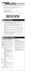
Operation Manual
Thank you for selecting the ZOOM 504 (hereafter simply called the "504").
Please take the time to read this manual carefully so you can get the most out of
your 504 and ensure optimum performance and reliability.
Retain this manual for future reference.
ZOOM CORPORATION
NOAH Bldg., 2-10-2, Miyanishi-cho, Fuchu-shi, Tokyo 183-0022, Japan
PHONE: 0423-69-7116 FAX: 0423-69-7115
Printed in Japan 504-5000
1 Major Features
• New type of compact multi-effect device designed for creating great acoustic guitar
sound.
• Suitable for use with an acoustic guitar or an electric guitar. Use the dedicated
effects for acoustic guitar, or make an electric guitar sound like an acoustic guitar
with the built-in simulator.
• Unique AIR effect imitates the sound as picked up by a microphone. Reverb and
chorus effects help to create a spacious feeling. Enjoy life-like, dynamic sound even
during line recording.
• Feedback suppressor automatically detects and attenuates problem frequencies.
This makes the 504 useful not only for line recording but also on stage.
• Two input jacks with different sensitivity allow optimum matching to any type of
guitar, from acoustic guitars with magnetic pickups to electric guitars with
humbucking type pickups.
• You can switch between 24 patches to store diverse settings based on your
preference.
• Integrated auto-chromatic tuner for guitar. You can tune your instrument easily
anywhere, any time. You can also leave the tuning function disabled all the time.
• Dual power supply design allows the unit to be powered from a 9V alkaline battery
(6LR61) or an AC adapter.
2 Safety Precautions
USAGE AND SAFETY PRECAUTIONS
In this manual, symbols are used to highlight warnings and
cautions for you to read so that accidents can be prevented. The
meanings of these symbols are as follows:
Warning
This symbol indicates explanations about extremely
dangerous issues. If users ignore this symbol and handle
the device incorrectly, serious injury or death could
result.
Caution
This symbol indicates explanations about dangerous
issues. If users ignore this symbol and handle the
device the wrong way, bodily injury and damage to the
equipment could result.
Please observe the following safety tips and precautions to ensure
hazard-free use of the 504.
About power
Warning
Since power consumption of this unit is fairly high, we
recommend the use of an AC adapter whenever possible.
When powering the unit from a battery, use only an alkaline
type.
AC adapter operation
• Be sure to use only an AC adapter which supplies 9 V DC,
300 mA and is equipped with a "center minus" plug (Zoom
AD-0006). The use of an adapter other than the specified type
may damage the unit and pose a safety hazard.
• Connect the AC adapter only to an AC outlet that supplies the
rated voltage required by the adapter.
• When disconnecting the AC adapter from the AC outlet,
always grasp the adapter itself and do not pull the cable.
• If the unit is not to be used for a long time, disconnect the AC
adapter from the outlet.
Battery operation
• Use only a 9 V (alkaline) battery (6LR61).
• The 504 cannot be used for recharging.
Pay close attention to the labelling of the battery to make sure
you choose the correct type.
• If the 504 is not to be used for an extended period of time,
remove the battery from the unit.
• If battery leakage has occurred, wipe the battery compartment
and the battery terminals carefully to remove all remnants of
battery fluid.
• While using the unit, the battery compartment cover should
be closed.
Environment
Caution
•
•
•
•
Avoid using your 504 in environments where it will be
exposed to:
Extreme temperature
High humidity or moisture
Excessive dust or sand
Excessive vibration or shock
Handling
Caution • The 504 is a precision instrument. Except for the foot
switches, do not push other parts with your feet or subject
them to strong force.
• Take care that no foreign objects (coins or pins etc.) or liquids
enter the unit.
• Be sure to turn the power to all equipment off before making
connections.
• Before moving the unit, turn the power off and disconnect all
cables and the AC adapter.
Alterations
Caution
Never open the case of the 504 or attempt to modify the
product in any way since this can result in damage to the unit.
Usage precautions
Electrical interference
For safety considerations, the 504 has been designed to provide
maximum protection against the emission of electromagnetic
radiation from inside the device, and from external
interference.However, equipment that is very susceptible to
interference or that emits powerful electromagnetic waves
should not be placed near the 504, as the possibility of
interference cannot be ruled out entirely.
Whatever the type of digital control device, the 504 included,
electromagnetic damage can cause malfunctioning and corrupt
or destroy data. Since this is an ever-present danger, thorough
care should be taken to minimize the risk of damage.
Cleaning
Use a soft, dry cloth to clean the 504. If necessary, slightly
moisten the cloth. Do not use abrasive cleanser, wax, or
solvents (such as paint thinner or cleaning alcohol), since these
may dull the finish or damage the surface.
Connecting cables and input and output jacks
You should always turn off the power to the 504 and all other
equipment before connecting or disconnecting any cables. Also
make sure to disconnect all cables and the AC adapter before
moving the 504.
3 What Are Banks and Patches?
4 PATCH LIST
• PATCH
The 504 has memory
capacity for 24 patches.
At the factory, these are
programmed with
recommended settings.
A group of the settings for a certain effect type is called a PATCH. The 504 comes with 24 preset
patches which can be changed (edited) by the user.
• BANK
The 504 calls up patches in sets of four, called a "bank".
BANK A – d for ACOUSTIC GUITAR
BANK A
DEMO
BANK b
WORLD
The user can Edit and Store
any patch, and also restore
the factory settings.
BANK C
PLAY
BANK F
BANK E
BANK d
BANK C
BANK b
BANK A
PATCH 1
PATCH 2
PATCH 3
PATCH 4
PATCH 1
PATCH 2
PATCH 3
PATCH 4
PATCH 1
PATCH 2
PATCH 3
PATCH 4
PATCH 1
PATCH 2
PATCH 3
PATCH 4
HINT
PATCH 1
PATCH 2
PATCH 3
PATCH 4
PATCH 1
PATCH 2
PATCH 3
PATCH 4
The patches of banks A
through d for acoustic
guitar are designed for
line output to a mixer or
similar. When using a
guitar amplifier, it is
recommended to adjust
the De-Amp parameter.
BANK d
ARTIST
Acoustic Master
Spacy-12
Gut Style
Studio Strum
J-Folk
Hawaiian Steel
Street Blues
Asian Dream
Studio Finger
Slide (Bottle)
Ragtime
Resonator
Green Flavor
Arpeggian
Virtuoso
Avant-Garde
1
2
3
4
1
2
3
4
1
2
3
4
1
2
3
4
Basic Acoustic sound with short reverberation
Simulated 12-string sound
Gut string simulation, good for solo play
Recording quality sound for strum
Folk guitar sound
Simulated Lap-steel guitar sound
Tight sound with room ambience
SFX making sound like ethnic instruments
Recording quality sound for finger picikng
Doubling sound for bottle-neck play
Natural sound with delay and reverb
Simulated "Dobro"sound
Freddie Green sound
Bright Arpeggio sound
Warm jazz guitar sound
Progressive acoustic sound
BANK E, F ACOUSTIC SIMULATION for ELECTRIC GUITAR
BANK E
DEMO
BANK F
STYLE
Standard
El-Acorustic
Warm Taste
12-Plus
Jumbo Type
Stage Strum
New-Strings
Rich Strum
1
2
3
4
1
2
3
4
Standard acoustic simulation sound
Piezo type electric-acoustic sound
Nylon-string type solo sound
Octave enhanced sound, good for solo and arpeggio
Jumbo body sound
Useful acoustic simulation sound
Bright acoustic sound
Acoustic 12-string simulation
* ACOUSTIC SIMULATION is suitable for single pickup at front position.
5 Configuration of Patches
The patches of the 504 are created using the nine parameters listed below. A parameter is an
element that determines a certain aspect, such as the sound character or the effect intensity.
Parameters can be altered by the user as desired, and a set of changed parameters can be stored as
a patch for later recall.
INPUT
TYPE
LIMITER/
EDGE
PRE AMP
LIMITER
SIMU
EDGE
BODY&
TOP
AIR
MODULATION
Global parameters are common to all patches.
For an explanation of the function of each parameter, please refer to section "11. Editing
Patches".
REVERB&
DELAY
OUTPUT
LEVEL
Parameters
Global parameters
F.B. SUPPRESSOR
De-AMP
Global parameters are common to all
patches. Their effect does not change
when switching patches. The global
parameter settings are stored in the
memory of the unit, along with patches.
Global parameters
Patch
6 Controls, Functions and Connections
Front Panel
OUTPUT
INPUT
TUNER indicator
A1
Indicator shows that tuning function is active and also serves to show the correct fine
tuning position.
• Edit mode
Indicator flashes when LEVEL parameter (overall patch level) is selected.
BANK HOLD
TYPE
• BATTERY EMPTY WARNING display
LIMITER/EDGE
Displays the selected bank (A-F) and patch (1-4).
COMPACT MULTI EFFECTS PROCESSOR
TYPE
PRE AMP for
ACOUSTIC Guitar
NATURAL
MILD
RHYTHM
BRIGHT
SIMULATOR for
ELECTRIC Guitar
NORMAL
JUMBO
PIEZO
GUT
BODY&TOP
STORE
+
AIR
TUNER CAL.
EDIT VAL.
BANK
MODULATION
STORE key
Displays information required to operate the 504.
• Play mode
• Bypass(Mute)/Tuner mode
When the unit is powered from the battery and the battery is running low, this
indicator begins flashing at a faster rate than in Edit mode. In such a case, replace the
battery as soon as possible.
DISPLAY
REVERB&DELAY
EDIT
–
De-AMP
When the contents of patches are to be stored, this key is used for putting the unit in
store standby status and to execute the store function.
F.B. SUPPRESSOR
LEVEL
• Setting of direct load function
DOWN
BYPASS
When the STORE key is pressed for at least 1 second during Play mode (during
performance), the direct load function can be switched on or off. [For details, see 10
Patch Switching (Application: Direct Load OFF).]
UP
• Edit mode
Displays the value of the selected effect parameter.
• Bypass(Mute)/Tuner mode
Shows the pitch of the input signal.
PARAMETER CURSOR indicator
• Play mode
The currently used effect module lights.
• Edit mode
The indicator lights up for the currently used effect module, and the indicator
flashes for the effect module that is turned off. Also, the indicator for the effect
module selected for editing flashes.
• Bypass(Mute)/Tuner mode
Indicators function as tuning meter.
VALUE +/- keys
• Play mode
EDIT key (for creating your own patches)
The keys serve for bank switching.
This key serves to toggle between the Play mode and Edit mode (mode for creating
patches to suit your taste).
In Edit mode, this key can be used to select the effect parameters you wish to change.
Also, when the effect parameter LEVEL is selected, press this EDIT key to return
from the Edit mode to the Play mode.
• Edit mode
The keys serve for changing the effect parameter.
• Bypass(Mute)/Tuner mode
The keys serve for setting the tuner reference pitch (calibration).
• Setting of bank hold function
When the EDIT key is held down for at least 1 second in Play mode, the bank hold
function is turned on or off. [For details, see 9 Patch Switching (Application: Bank
Hold ON).]
PATCH UP (right)/DOWN (left) pedals
• Play mode
The pedals serve for patch switching. Pressing both pedals simultaneously
activates the Bypass(Mute)/Tuner mode.
• Edit mode
The pedals serve for selecting effect parameters. Pressing both pedals
simultaneously turns the currently selected effect module on or off.
• Bypass(Mute)/Tuner mode
Pressing either pedal cancels the Bypass(Mute)/Tuner mode to return to Play
mode.
Rear Panel
CONTROL IN jack
INPUT
DC 9V
CONTROL IN
OUTPUT
INPUT jack
Serves for connection of an acoustic or electric guitar. Choose the HIGH or LOW
input, according to the output level of the pickup.
• HIGH:
For electric guitars with single-coil pickups or acoustic guitars with magnetic
pickups.
• LOW:
For electric guitars with humbucking or active type pickups, or for electroacoustic
guitars.
When the unit operates on batteries, the INPUT jack doubles as a power switch.
Plugging in a shielded cable turns the 504 on. To prevent draining the battery, unplug
the cable when the unit is not in use.
DC IN (AC adapter) jack
Serves for connecting an AC adapter (Zoom AD-0006) which delivers 9 VDC, 300
mA with a "center minus" plug configuration. The 504 is powered on by plugging
an AC adapter into this jack.
ZOOM CORPORATION
HIGH
LOW
MADE IN JAPAN 300mA
(PHONES)
The optional FP01 expression pedal or FS01 foot switch can be connected here,
for external control of the 504.
When the expression pedal FP01 is connected, the pedal controls the output level.
When the foot switch FS01 is connected, the switch turns the F.B.SUPPRESSOR
function on and off. For a detailed explanation, please refer to section "12. Effect
Parameters".
NOTE:
Before connecting or disconnecting the FP01 or FS01, make sure that the 504 is switched
off. Otherwise malfunction can occur.
OUTPUT jack
This jack is for the output signal from the 504. You can connect either a single
guitar amplifier, using a monaural shielded cable, or two guitar amplifiers, using a
Y-type stereo shielded cable, or a pair of stereo headphones. If the volume level is
low when using headphones, use headphones with low impedance (32 ohms or
less).
7 Selecting Patches
A1
A1
Bank switching
Banks A, b, C, d, E, F are available
PATCH
DOWN
BANK F
PATCH
UP
PATCH 1
PATCH 2
PATCH 3
PATCH 4
Patch switching
24 patches are available
BANK E
PATCH 1
PATCH 2
The 24 patches can be easily selected by
pressing the patch pedals. The right patch
pedal switches to the next patch and the
left patch pedal switches to the previous
patch.
PATCH 3
PATCH 4
BANK UP
BANK d
PATCH 1
PATCH 2
In the initial condition, the 504 is set up
so that the patch pedals select patches
continuously, but you can also set up the
unit so that patches are switched only
within a certain bank of four patches. [For
details, see section 9 Patch Switching
(Application: Bank Hold ON).]
A1
PATCH 3
PATCH 4
BANK C
PATCH 1
PATCH 2
BANK DOWN
PATCH 3
PATCH 4
Banks are selected with the VALUE +/keys. Press the VALUE+ key to select the
next bank, and the VALUE- key to select
the previous bank.
BANK b
PATCH 1
PATCH 2
For example, to switch from Patch 2,
Bank A to Patch 3, Bank C, the patch
pedal would have to be pressed nine
times. Instead, you can press the
VALUE+ key twice to switch to Bank C,
and then press the patch pedal (UP) just
once to select Patch 3.
PATCH 3
PATCH 4
BANK A
PATCH 1
PATCH 2
Bank/patch switching
when Bank Hold is off
(initial setting)
PATCH 3
PATCH 4
8 Using the Bypass (Mute)/Tuner Mode
In the Bypass mode, the effects of
the 504 are temporarily turned off,
so that the original sound of the
instrument only is heard. In this
mode, the auto-chromatic tuning
function is also active. It is also
possible to activate muting, to
prevent the tuning sound from
being sent to the output.
Bypass and mute condition
Calibration
A1
Select reference pitch for auto-chromatic
guitar tuner (calibration).
* The reference pitch (A) can be adjusted in the
rangefrom 435 to 445 Hz. When the BANK key
is pressed in Bypass (Mute)/Tuner mode, this is
shown as "35" to "45" on the display for a
second. Adjust to the suitable value. At poweron, the setting is 440 Hz (40).
Bypass (Mute)/Tuner mode ON
Press both
pedals together
Pressing both patch pedals simultaneously turns
the Bypass (Mute)/Tuner mode on. To turn the
mode off, simply press one of the two patch pedals.
Pressing both patch pedals simultaneously activates the Bypass or Mute mode.
• For bypass mode: Press and immediately release the patch pedals.
Currently selected
patch is indicated
Press
Release immediately
Tuner mode
• For mute mode: Press patch pedals for at least 1 second.
Currently selected
patch is indicated
Press for 1 s or more
Release
Mute mode
To cancel the bypass or mute condition, simply press one of the patch pedals. The unit then
reverts to the previously selected patch.
Tuner mode
The 504 is initially set so that the auto-chromatic tuning function for the guitar activates
automatically when the Bypass(Mute) mode is invoked. In Bypass(Mute) mode, pick an open
string to be tuned. The closest note will be shown on the display.
Input signal
standby condition
Regular tuning
Do = C
Fa# = F#
Re# = D#
Regular tuning
Do# = C#
Mi = E
6th string
1st string
So = G
Regular tuning
Re = D
La = A
5th string
Regular tuning
3rd string
La# = A#
Regular tuning
4th string
Fa = F
So# = G#
Si = B
2nd string
When the tuning function is active, the parameter cursor LEDs
serve as tuning meter, designed to enhance tuning precision
during fine adjustments.
Turning tuning function off
If you do not want to activate the tuning function in
Pitch is too high Correctly tuned
Pitch is too low
Bypass(Mute) mode, press the STORE and EDIT keys
simultaneously for more than one second in Play mode. The
tuning function will be turned off, and this setting will be stored even when the power is turned
off. When you turn the function off, the display will show "tunEr oFF" (tuning function off).
To turn the tuning function on, press the same keys simultaneously again. The display will show
"tunEr on" (tuning function on).
NOTE: Please note that the tuning function may not operate properly if other effect modules between the
guitar and the 504 are on.
9 Patch Switching (Application: Bank Hold ON)
In the initial setting, the patch
pedal switches all patches in
order, regardless of the bank
divisions.
Bank Hold ON
Keeping the EDIT key depressed for at least 1 second activates Bank
Hold. To cancel Bank Hold, press the EDIT key again for 1 second.
The bank hold function limits
switching to the four patches
within a bank. When this
function is activated, the patch
pedals switch in order between
the patches in the current bank
only.
A1
Bank switching
Banks A, b, C, d, E, F
can be switched.
To activate this function, hold
the EDIT key down for at least
1 second in Play mode. The
BANK HOLD indicator will
light. To turn the function off,
again hold the EDIT key down
for at least 1 second. The
BANK HOLD indicator will go
off.
PATCH
DOWN
PATCH
UP
Patch switching
4 patches within bank can be switched.
Banks can be switched using
the VALUE +/- keys.
Bank/patch switching
when Bank Hold is on
A1
BANK F
PATCH 1
BANK E
PATCH 1
PATCH 2
PATCH 1
PATCH 2
PATCH 2
PATCH 3
PATCH 4
PATCH 1
PATCH 1
PATCH 2
PATCH 1
PATCH 2
PATCH 2
PATCH 3
PATCH 4
PATCH 3
PATCH 4
PATCH 3
PATCH 4
PATCH 3
PATCH 4
BANK d
BANK C
BANK b
BANK A
PATCH 3
PATCH 4
A.1
BANK HOLD ON
NK
UP
BA
NK
BA
A1
A.1
DO
BANK HOLD OFF
WN
10 Patch Switching (Application: Direct Load OFF)
In the default condition, the 504 is
set up in such a way that pressing a
patch pedal immediately switches
the patch and alters the output
sound. This is called Direct Load
ON. This switching principle is
most convenient when the desired
patches are adjacent or close to
each other. However, when
wanting to switch to a patch that is
further away, it may be desirable
not to activate the sound of the
other patches in between.
DIRECT LOAD OFF
Keeping STORE key depressed for 1 second
turns Direct Load off.
The same procedure serves to turn it on.
A1
Bank switching
Banks A, b, C, d, E, F
can be switched.
PATCH
DOWN
When this is desired, turn the
Direct Load function off as
follows. When Direct Load has
been turned off, switching banks
and patches has no effect until the
user confirms the selection.
PATCH
UP
Patch switching
Patches can be switched.
For example, when going from
patch 1 to patch 4 with Direct Load active, patches 2
and 3 will briefly be heard when the patch UP pedal
is pressed three times. When Direct Load is off,
pressing the patch UP pedal will change the number
on the display (the number flashes), but until the
user confirms the choice, the sound remains that of
patch 1.
Confirming a patch
When display indication flashes, pressing
both patch pedals together confirms the
patch and switches the output sound.
A4
To turn Direct Load on or off, keep the STORE key
depressed for at least 1 second.
To confirm a choice after selecting a patch with
Direct Load off, press both patch pedals
simultaneously.
Press both pedals together
Example: Switching from patch 1 to patch 4
A1
A2
A3
A4
A4
Patch switching completed
Confirm
11 Editing Patches
• REVERB & DELAY: Adjusts the reverberation effect. Depending on the parameter setting, a mix of delay
and reverb can be created to increase the depth of the sound.
• De-AMP: Serves to control the frequency range that can be sonically unpleasant when reproducing the
sound of an acoustic guitar over an electric guitar amplifier.
• F.B.SUPPRESSOR: Reduces feedback which can occur easily when using an acoustic guitar during a live
performance.
• LEVEL: Adjusts the overall level of the patch.
The 504 comes with 24 predefined patches. However, the 504 offers many more possibilities for
combining effects in innovative ways. To discover these possibilities, we recommend that you try
changing the parameters (elements that make up patches) to create your own patches. This operation is
called editing, and is done in the Edit mode.
A1
P8
To switch from normal Play mode to Edit mode, press
the EDIT key briefly (for less than 1 second).
* Note that if the EDIT key is held down for 1 second or
longer, the Bank Hold mode will be activated.
Each push of the EDIT key moves the blinking parameter cursor indicator one step down. The TUNER
indicator serves as parameter cursor for the LEVEL parameter. When the EDIT key is pressed while the
lowest indicator (F.B.SUPPRESSOR) is flashing, the TUNER indicator starts flashing and the LEVEL
parameter can be adjusted.
The parameter value is changed using the VALUE +/- keys. For details on parameters, please refer to
section "12. Effect Parameters".
To terminate the Edit mode and return to the Play mode, press the EDIT key while the LEVEL
parameter is selected (TUNER indicator is flashing). For information on how to store changed
parameters, please refer to section "13. Storing Patches".
When the PATCH
DOWN pedal is pressed
7
8
10
A1
instead of the EDIT
key, the TYPE
parameter is selected
again and the unit does (1) Use the EDIT key or patch (2) Use the VALUE +/- keys (3) While the TUNER indicator
pedal to select the parameter
to adjust the parameter.
(Parameter 9:LEVEL) is flashing, press
not return to the Play
you wish to change.
the EDIT key to return to Play mode.
mode.
(1) While still in Play mode, select (2) Press the EDIT key to
Immediately after switching from Play mode to Edit
the patch you wish to edit.
activate the Edit mode.
mode, the TYPE parameter cursor is flashing, and the
TYPE setting is shown on the display. This indicates that the TYPE parameter is currently selected for
editing.
In Edit mode, the EDIT key or PATCH UP/DOWN pedals are used to select the parameter for editing.
The 504 has the following parameters:
• TYPE: Selects the preamp module type. Make the selection according to the connected type of guitar and
the desired application.
• LIMITER/EDGE: Depending on the setting of the TYPE parameter, this parameter enhances the edge of
the guitar string sound or compresses the dynamic range.
• BODY & TOP: Emphasizes the lower frequency range (BODY) or upper frequency range (TOP), causing a
voluminous sound or making the sound brighter and more distinct.
• AIR: Simulates sound as if captured with a microphone.
• MODULATION: Lends a soft expansive feeling to the sound, using a chorus effect. Depending on the
parameter setting, an octave-higher component can be added, to emulate the sound of a 12-string guitar.
12 Effect Parameters
PRE AMP for ACOUSTIC Guitar
PARAMETER 1 : TYPE
When using an acoustic guitar, this parameter serves for
making preamplifier settings. When using an electric guitar, the
parameter serves for making acoustic guitar simulator settings.
Pressing one of the VALUE +/- keys
increases or decreases the setting
by one step.
+
–
VALUE +/- keys
PARAMETER 2 : LIMITER / EDGE
Depending on the setting
of the TYPE parameter,
this parameter either
controls the dynamic range
or the sharpness of the
sound.
Increases or decreases
the setting by 1.
Increases or decreases
the setting by 1.
+
1 — 15
Jb (jumbo):
PE (piezo):
Gt (gut):
nr
Jb
PE
Gt
Simulates the
sound of a
traditional acoustic
guitar.
Simulates the sound
of a large-bodied
acoustic guitar.
Simulates the sound of
an acoustic guitar with
a piezo pickup.
Simulates the
sound of a
classical guitar with
nylon strings.
When one of the settings nr, Jb, PE, Gt (for electric guitar) is selected for the TYPE
parameter, the LIMITER/EDGE parameter works as an EDGE effect that enhances
the sharpness of the guitar string sound.
Controls the limiter intensity. Larger values result in
stronger limiter effect (more narrow dynamic range).
1 — 15
Controls the EDGE effect. Larger values result in
more pronounced string sound.
* The effect of the BODY & TOP parameter differs, depending on whether a setting for acoustic
guitar (na, Md, ry, br) or electric guitar (nr, Jb, PE, Gt) is selected for the TYPE parameter.
–
+
b1 — b9
–
Adjusts the lower frequency range (BODY).
Higher values result in more voluminous
sound.
t1 — t9
Adjusts the upper frequency range (TOP).
Higher values result in brighter sound.
E1 — E9
Simultaneously adjusts the lower frequency range
(BODY) and upper frequency range (TOP). Higher
values result in a more pronounced effect.
The parameter lets you create an airy, expansive sound even during line recording.
Increases or decreases
the setting by 1.
Increases or decreases
the setting by 1.
+
–
C1 — C9
Deep and rich chorus effect. Higher values result in a stronger effect.
t1 — t9
Simulates the sound of a 12-string guitar. Higher values increase the intensity of
the effect.
c1
Light chorus effect with emphasis on the original sound. Higher values
result in a stronger effect.
d1 — d9
Creates a doubling effect as if two similar instruments were played at the same time.
Higher values result in a stronger shift between effect sound and original sound.
—
c9
The parameter controls simulated reverberation and echo (delay).
Some settings allow use of both effects together.
+
–
L1 — L9
Simulates reverberation in a fairly large room. Higher values result in
stronger reverb.
d1 — d9
Creates a delay effect. Higher values result in longer echo intervals.
S1 — S9
Simulates reverberation in a fairly small room. Higher values result in
stronger reverb.
r1 — r9
Creates a mixed reverberation and delay effect. Higher values result in stronger
reverb and longer echo intervals.
VALUE +/- keys
Skips to S1 if current setting is
L1 - L9, to d1 if S1 - S9, etc.
Increases or decreases
the setting by 1.
+
–
+
–
VALUE +/- keys
Skips to c1 if current
setting is b1 - b9, to S1
if c1 - c9, etc.
+
–
PARAMETER 8 : F.B. SUPPRESSOR
Increases or decreases
the setting by 1.
Skips to 1 if current setting is
SC, to 10 if 1 - 9, to 20 if 10
- 19, etc.
Adjusts the simulated mike position. Higher values move the
simulated microphone further away from the guitar.
+
–
VALUE +/- keys
Skips to c1 if current setting is
C1 - C9, to t1 if c1 - c9, etc.
1 — 10
The parameter creates a wide sound stage by adding a chorus effect.
Some settings result in a 12-string guitar sound.
PARAMETER 7 : De-AMP
Global parameters
Tight sound best Bright sound best
suited for stroke suited for
playing.
fingering.
Increasing the BODY value results in a more voluminous sound, and
increasing the TOP value makes the sound brighter and more distinct.
PARAMETER 6 : REVERB & DELAY
This parameter serves for
suppressing feedback
which can occur when
using an acoustic guitar
during a live performance.
The frequency range for the
parameter can be selected.
rY
Changes even the
sound of piezo
pickups to a
warm sound.
+
PARAMETER 5 : MODULATION
This parameter serves to
control the frequency range
that can be sonically
unpleasant when reproducing
the sound of an acoustic guitar
over an electric guitar amplifier.
nr (normal):
br
Md
* The limiter can be adjusted also when the TYPE parameter is off.
+
Increases or decreases
This parameter imitates
the setting by 1.
–
the way a guitar sounds
VALUE +/- keys
when picked up by a
+
Skips to 10 if current setting is 1 - 9.
microphone.
–
This parameter adds
reverb and delay to the
original sound.
br (bright):
–
PARAMETER 4 : AIR
This parameter lends a
wide, spacious feeling to
the sound.
ry (rhythm):
n6
+
VALUE +/- keys
Skips to t1 if current setting is b1
- b9, and to E1 if t1 - t9.
Md (mild):
Natural sound
suitable for
almost any genre
and playing style.
–
PARAMETER 3 : BODY & TOP
This parameter adjusts
the lower frequency
range (BODY) or upper
frequency range (TOP).
na (natural):
When using an electric guitar, select one of the settings nr, Jb, PE, Gt. These settings control the
acoustic guitar simulator which makes an electric guitar sound like an acoustic guitar. Each setting
gives a different sound character.
When one of the settings na, Md, ry, br (for acoustic guitar) is selected for the TYPE
parameter, the LIMITER/EDGE parameter works as a limiter that compresses the
dynamic range.
VALUE +/- keys
Skips to 10 if current setting
is 1 - 9, and to 15 if 10 - 14.
SIMULATOR for ELECTRIC Guitar
When using an acoustic guitar, select one of the settings na, Md, ry, br. These
settings control the dedicated acoustic guitar preamplifier, each giving a different
sound character. Choose the setting that is best matched to your playing style.
When using an electroacoustic guitar,
depending on the amplifier and pickup type,
certain frequency ranges can sound
unpleasant or grating to the ear. By adjusting
the De-AMP parameter, this phenomenon
can be reduced. The following three setting
ranges are available. Choose one that is
most effective for your playing technique.
b1 — b9
Reduces certain offending frequencies likely to occur
with a bright combo type guitar amplifier. Higher values
result in more effective suppression.
c1
Reduces certain offending frequencies likely to occur
with a combo type guitar amplifier. Higher values result
in more effective suppression. The frequency range
differs from the b1 - b9 settings.
—
c9
S1 — S9
Reduces certain offending frequencies likely to occur
with a stack type guitar amplifier. Higher values result
in more effective suppression.
* The De-AMP parameter is a global parameter which
works on all patches.
Feedback is reduced by attenuating a selectable frequency range (feedback frequency).
The frequency range can be selected either automatically or manually.
+
SC
–
VALUE +/- keys
+
–
This setting serves to automatically detect the
feedback frequency while playing. By selecting
"SC" when feedback occurs, the frequency is
detected (this process requires about one second),
and attenuation is then applied automatically.
The detection occurs whenever the setting is switched to
1 — 30
"SC" from the "1"setting, or if the F.B.SUPPRESSOR
parameter is turned from off to on (by pressing the PATCH
UP/DOWN pedals simultaneously), with "SC" selected.
While the frequency is being detected, the parameter cursor
flashes and the pedals and keys of the unit are inactive.
Allows manually adjusting the feedback
suppression range. The higher the setting, the
higher the feedback frequency.
* The F.B.SUPPRESSOR parameter is a global parameter
which works on all patches.
PARAMETER 9 : LEVEL
This parameter serves to
adjust the overall level of
the patch.
Increases or decreases
the setting by 1.
Skips to 10 if 1 - 9, to 20 if 10 - 19, etc.
+
1 — 30
–
VALUE +/- keys
The higher the setting, the higher
the overall patch level.
+
–
HINT
!
Selection of parameters to change
As described in 11. Editing Patches, parameters to be edited are selected by
repeatedly pressing the EDIT key, but you can also use the patch pedals for
this purpose.
Press the PATCH UP pedal (right patch pedal) to move the parameter
cursor from the bottom up.
Press the PATCH DOWN pedal (left patch pedal) to move the parameter
cursor from the top down.
HINT
@
Switching parameters on and off
Except for LEVEL, any selected parameter can be turned on or off by
pressing the PATCH UP/DOWN pedals simultaneously. The on/off
condition can also be stored as part of the patch.
• To switch a parameter on or off:
When any parameter except LEVEL is selected in the Edit mode, pressing
the PATCH UP/DOWN pedals simultaneously turns the parameter off.
(The indication "oF" appears on the display.) The parameter can be
turned on again either by pressing the PATCH UP/DOWN pedals
simultaneously once more, or by pressing one of the VALUE +/- keys.
The parameter setting that was active before will be reestablished.
* When the F.B.SUPPRESSOR parameter is set to "SC", turning the
parameter off and on again will cause the automatic feedback frequency
detection to be performed once more. The frequency setting therefore
may be different after the parameter is turned on again.
HINT
#
Parameter setting shortcuts
Normally, parameter values are set by tapping the VALUE + or VALUE –
key once for each increment or decrement. For quick operation, you can
use the shortcut function. This is activated in the Edit mode by pressing
both VALUE keys together.
For example, if the LEVEL parameter is set to "20" and you want to change
it to "29", you would have to press the VALUE + key 9 times. Instead, you
can achieve the same effect by using the shortcut function: press the
VALUE +/– keys together, which will change the value to "30" and then
press the VALUE – key once to arrive at "29".
HINT
$
Using the F.B.SUPPRESSOR
(1) Detecting feedback frequency automatically in Edit mode
Select a different setting for F.B.SUPPRESSOR and then select "SC", or
turn the parameter off and then on again while "SC" is selected.
(2) Adjusting feedback frequency manually in Edit mode
If feedback attenuation in "SC" mode is not satisfactory, try setting the
F.B.SUPPRESSOR parameter manually to a value between 1 and 30 to
find the setting which yields optimum suppression.
(3) Detecting feedback frequency automatically in Play mode
In order to be able to automatically detect the feedback frequency while
playing the guitar, you must first set the F.B.SUPPRESSOR parameter
to "SC". In Play mode, you can then turn the parameter off and on again
by pressing the foot switch FS01 twice. The feedback frequency will be
detected automatically, and suppression will be active.
* During the detection interval (about one second), do not turn down the
guitar volume or change other settings.
* If the F.B.SUPPRESSOR parameter is set to 1 - 30, switching the
parameter off and on again will not cause automatic feedback
frequency detection.
* In either case, the F.B.SUPPRESSOR parameter setting will be stored
when the currently selected patch is stored.
HINT
%
Master level adjustment
With the 504 you are also able to set the master level that governs the
overall output level.
The master level is adjusted in Play mode. Hold the VALUE +/– keys down
simultaneously for at least 1 second. The current master level will be
displayed for 1 second.
While the level is being displayed, use the VALUE +/– keys to change it.
The setting range is 0 –50. (Default value = 40)
The unit does not store the setting for the master level. Each time the power
is turned on it has to be set again.
13 Storing Patches
If you have edited (altered) a patch and turn the 504 off without storing the patch, the patch will revert
to its old setting. To store an edited patch, use the following simple procedure.
Storing can be carried out in both Play mode and Edit mode.
After you have edited the patch, press the STORE key. If the unit is currently in Play mode, release
the key before 1 second has elapsed, otherwise the Direct Load function will be activated.
The display starts to flash. This condition is called the store
NOTE
standby condition. If you wish, you can abandon the store
procedure at this point by pressing the EDIT key. If you press When a patch is stored, the current
the STORE key once more, the contents of the patch are settings of the global parameters (DeAMP, F.B.SUPPRESSOR) are also
updated.
stored. If the parameter settings were
You can also change the patch number before storing, so that the changed and the unit is turned off
edited patch will be stored in a different number.
without storing the patch, the
In this case, the original patch that was used as a starting point parameters will revert to the old
settings.
for editing will not be changed.
(2) Press the STORE key.
(Unit enters store standby mode.)
A1
A1
(4) Press the STORE key once more.
(Store process is completed.)
b4
b4
(1) Edit the patch as desired.
b4
(3) Select the patch for storing.
14 Replacing the Battery
If the tuning indicator flashes while the unit is being powered from the battery, the battery is
exhausted and should be replaced as described below.
Use only a 6LR61 9 V (alkaline) battery.
Using another kind of battery will result in shorter operation.
Cover
6LR61 9 V (alkaline) battery
Cable
1. Turn the 504 upside down and
open the cover of the battery
compartment. (Push the catch to
unlock the cover, then lift it up.)
2. Remove the battery from the
compartment and disconnect the
battery cable. (Grasp the
terminal strip and do not pull at
the cable.)
3. Connect the battery cable to the
new battery, taking care to
observe correct polarity (+/-).
Then insert the battery into the
battery compartment.
4. Close the battery compartment
cover, taking care not to pinch the
cable. (Make sure that the cover
is properly locked.)
15 Returning Patches to Factory Settings
The 504 comes with 24 predefined patches that have been programmed at the factory. Also after
you have edited and stored your own patches, you can return to the factory default settings at any
time. This process is called "recalling". Returning all 24 patches to the original contents and
resetting the Bank Hold and Direct Load functions is called "all initialize".
The Recall mode is separate from the Play mode and Edit mode. You cannot switch directly to
Recall mode from these modes. The Recall mode can only be activated by turning the unit on in
a special way, as described below.
1.
2.
3.
4.
Turn the unit off by disconnecting the AC adapter or the guitar input cable.
Keep the STORE key depressed and turn the unit on.
The indication "AL" flashes on the display.
To perform "all initialize", press the STORE key once more in this condition. The
flashing rate increases and the initialization procedure is carried out. When it is
completed, the unit automatically enters the Play mode.
5. When wishing to recall only a particular patch, select the patch number in step 3,
using the same procedure as for normal patch selection.
6. When the desired patch has been selected, press the STORE key. The flashing rate
increases and the contents of the selected patch are recalled.
7. Recalling of individual patches can be carried out continuously. When you wish to
terminate the process, press the EDIT key. The unit then returns to the Play
mode. Turning the unit off also terminates the recall condition.
16 Specifications
Effects:
Banks and Patches:
Analog/Digital Conversion:
Digital/Analog Conversion:
Sampling Frequency:
Inputs:
Output:
Control Input:
Display:
Power Requirements:
Dimensions:
Weight:
26 effects
• TYPE
PRE AMP (for ACOUSTIC GUITAR)
ACOUSTIC SIMULATOR ( for ELECTRIC GUITAR )
• LIMITER (TYPE:PRE AMP,TYPE OFF)
EDGE
(TYPE:ACOUSTIC SIMULATOR)
• BODY&TOP
• AIR
• MODULATION
• REVERB&DELAY
• De-AMP
• F.B. SUPPRESSOR
Maximum simultaneous effects:8
6 banks X 4 patches = 24 patches (edit + store possible)
18 bit,128 times oversampling
16 bit, linear
31.25 kHz
HIGH input (standard monaural phone jack) Input impedance: 470kilohms
Rated input level: Electric Guitars with single-coil pick ups
Acoustic Guitars with magnetic pick ups
LOW input (standard monaural phone jack) Input impedance: 470kilohms
Rated input level: Electric Guitars with hum-bucking typ active type
Electric Acoustic Guitar
Combined line/headphone output(standerd stereo phone jack)
Max. output level: +6 dBm Output load impedance: 10 kilohms or more
For optional FP01 or FS01
2-digit,7-segment LED,tuning indicator,parameter cursor indicator
Optional AC adapter 9 VDC,300mA (ZOOM AD-0006)
Battery: 6LR61 9V (alkaline) battery X 1
Battery life: Approx. 4h continuous operation
147(W) X 157(D) X 49(H) mm
480 g (without batteries)
* 0 dBm = 0.775 Vrms
* Design and specifications subject to change without notice.