1
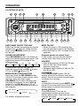
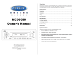
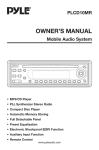
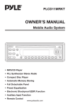
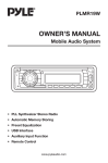
MS1550
MS1550B
OWNER’S MANUAL
Marine Audio System
POWER
MS 1550
VOL
4 x 40W
MUT
EQ
SEL
MENU
MONO
BAND
LOUD
VOL
SCAN
MODE
1
2 SCN
3 RPT
4 SHF
5 DISC-
6 DISC+
AMS
DISP
SHIFT
•
•
•
•
•
•
•
•
•
•
Electronic AM/FM tuner with US/Euro selection
Single CD player; plays CD, CD-R, CD-R/W
LED backlit controls, silicone rubber keypad
Marine features; solid top cover, corrosion resistant
hardware, coated circuit boards, uV stable plastics
Maintains settings with no power applied
CD changer controls (optional MCD10 changer)
Wired remote option (REMMS1550)
Aux input and line level outputs
4x40W power
Two wire power connection (Switched 12V and ground)
CONTENTS
Selecting disc ....................................9
Disc notes .............................................9
Specification......................................10
Trouble shooting ...............................11
Installation ...........................................3
Take out screw before installation.........3
DIN Front-Mount ..................................3
Installing the unit ...................................3
Removing the unit .................................4
Wiring Connection ..............................5
Operation .............................................6
Location of keys....................................6
Switching on/off the unit .......................6
Sound adjustment.................................6
Menu selection function........................6
Loudness ..............................................7
Set the clock .........................................7
Mute ......................................................7
Equalization...........................................7
Liquid crystal display ............................7
Reset function .......................................7
Radio operation ....................................7
Switching to radio mode ...................7
Selecting the frequency band............7
Selecting station ................................7
Automatic memory storing &
program scanning..............................7
Station storing ...................................7
Mono/stereo ......................................7
Scan...................................................7
CD operation.........................................8
Switching to CD mode ......................8
Selecting tracks .................................8
Pausing playing .................................8
Previewing all tracks..........................8
Repeating the same track .................8
Playing all tracks in random ..............8
Ejecting a disc ...................................8
CDC operation ......................................8
Switching to CDC mode .......................8
Selecting tracks .................................8
Pausing playing .................................8
Previewing all tracks..........................8
Repeating individual tracks or whole
CDs....................................................8
Playing all tracks in random ..............8
2
INSTALLATION
Notes:
TAKE OUT SCREW BEFORE
INSTALLATION
• Choose the mounting location where
the unit will not interfere with normal
vehicle operation.
Before install the unit, please remove the
two screws.
Take out screw before installation
• Before finally installing the unit,
connect the wiring temporarily and
make sure the unit and the system
work properly.
• Use only the parts included with the
unit to ensure proper installation.
The use of unauthorized parts can
cause malfunctions.
DIN FRONT-MOUNT
• Consult with your nearest dealer if
installation requires the drilling to holes
or other modifications of the vehicle.
Installation Opening
This unit can be installed in any dashboard
having an opening as show below:
• If installation angle exceeds 30˚ from
horizontal, the unit might not give its
optimum performance.
53 mm
30˚
182 mm
Installing the unit
Be sure you test all connections first, and
then follow these steps to install the unit.
1. Make sure the ignition is turned off,
and then disconnect the cable from
the vehicle's negative (-) battery
terminal.
2. Disconnect the wire harness and the
antenna.
3. Lift the top of the outer trim ring then
pull it out to remove it.
4. The two supplied keys release tabs
inside the unit's sleeve so you can
remove it. One key is for the right side
and the other is for the left side. Insert
the keys as far as they will go (with the
notches facing up) into the appropriate
slots at the middle left and right sides
of the unit. Then slide the sleeve off
the back of the unit.
• Avoid installing the unit where it would
be subject to high temperature, such
as from direct sunlight, or from hot air,
from the heater, or where it would be
subject to dust, dirt or excessive
vibration.
DIN FRONT/REAR-MOUNT
This unit can be properly installed either
from “Front” (conventional DIN Frontmount) or “Rear” (DIN Rear-mount
installation, utilizing threaded screw holes
at the sides of the unit chassis).
For details, refer to the following
illustrated installation methods.
3
INSTALLATION
Spring Washer
Sleeve
L Key
Outer Trim Ring
Hex Nut
Metal Strap
Mounting Bolt
Plain Washer
Tapping Screw
R Key
5. Mount the sleeve by inserting the sleeve
into the opening of the dashboard and
bend open the tabs located around the
sleeve with a screwdriver. Not all tabs
will be able to make contact, so
examine which ones will be most
effective. Bending open the
appropriate tabs behind the dashboard
to secure the sleeve in place.
9. Reconnect the cable to the vehicle
battery's negative (-) terminal.
Removing the unit
1. Make sure the ignition is turned off,
and then disconnect the cable from
the vehicle battery's negative (-)
terminal.
2. Remove the metal strap attached the
back of the unit (if attached).
3. Lift the top of the outer trim ring then
pull it out to remove it.
4. Insert both of the supplied keys into
the slots at the middle left and right
sides of the unit, then pull the unit out
of the dashboard.
Dashboard
Tabs
Screwdriver
Sleeve
6. Reconnect the wire harness and the
antenna.
7. Slide the unit into the sleeve until it
locks into place, being careful not to
pinch any wires or cables.
8. To further secure the unit, use the
supplied metal strap to secure the back
of the unit in place. Use the supplied
hardware (Hex Nut (M5mm) and Spring
Washer) to attach one end of the strap
to the mounting bolt on the back of
the unit. If necessary, bend the metal
strap to fit your vehicle's mounting
area. Then use the supplied hardware
(Tapping Screw (5x25mm) and Plain
Washer) to attach the other end of
metal strap to a solid metal part of the
vehicle under the dashboard. This strap
also helps ensure proper electrical
grounding of the unit.
4
WIRING CONNECTION
RED
Rch
WHITE
(BLACK)
Lch
AV IN CABLE (YELLOW)
WIRING REMOTE
CONNECTOR SOCKET
(BLACK)
CD CHANGER
CONNECTOR SOCKET
FUSE
ANTENNA CONNECTOR
Output RCA CABLE (GREY) RED
Rch
WHITE
BLUE
YELLOW
BLACK
FRONT Lch
SPEAKER
WHITE
GREY
WHITE/BLACK
GREY/BLACK
REAR Lch
SPEAKER
GREEN
VIOLET
GREEN/BLACK
VIOLET/BLACK
Lch
POWER ANTENNA
+12V POWER
GROUND (B-)
FRONT Rch
SPEAKER
REAR Rch
SPEAKER
Note: This unit is designed to use a switched 12V power lead such as the vehicle's IGN
lead or the ACC lead. It is not recommended to use a constant 12V supply (MEM) for power.
5
OPERATION
LOCATION OF KEYS
9
11
10 17
5
8
1
7
4
3
POWER
MS 1550
VOL
4 x 40W
MUT
EQ
SEL
MENU
MONO
BAND
LOUD
VOL
SCAN
MODE
1
2 SCN
3 RPT
4 SHF
5 DISC-
6 DISC+
AMS
DISP
SHIFT
16 2
12
6
19
20
21 14 22
23
24
18
15 25 13
SWITCHING ON/OFF THE UNIT
Switch on the unit by pressing any button
(except and button (4)). When system
is on, press POWER button (9) to turn
off the unit.
BEEP ON/OFF
• When the beep is ON, pressing any
key will generate a tone in the speaker.
• When the beep is OFF, no tones will be
generate.
SOUND ADJUSTMENT
Press SEL/MENU button (10) shortly to
select the desired adjustment mode. The
adjustment mode will change in the
following order:
Program power on volume level
In this mode, you can set the desired
volume level when the unit turns on.
VOL
(Volume)
BAS
(Bass)
TRE
(Treble)
BAL
(Balance)
USA/EUR
• USA radio spacing is 200k for FM and
10k for AM. This is the default
frequency spacing.
• European radio spacing is 50k for FM
and 9k for AM.
FAD
(Fader)
The selected function can then be
adjusted by pressing the VOL button
(11) or the VOL button (12).
LOUDNESS
Press BAND/LOUD button (13) for
several seconds to reinforce the bass
output. Press it for several seconds again
to release this function.
MENU SELECTION FUNCTION
Press and hold the SEL/MENU button
(10) for 2-3 seconds to enter menu select
function, then step short press
SEL/MENU (10) to select different set
mode and separately to press VOL
button (11) or VOL
button (12) to
select your desired settings as shown in
the diagram.
BEEP ON/OFF
12hours/24hours
MUTE
In radio/AUX IN mode, press MUTE/
button (3) to mute audio level. Press the
button again to release mute function.
EQUALIZATION
Press EQ button (7) to turn on
equalization function and to select
desired audio mode. There are four kinds
of mode as below:
Program power on volume level
USA/EUR
For details, please see below:
FLAT
6
CLASSIC
POP M
ROCK M
OPERATION
Press the AMS button (18) briefly to
scan the station preset memories. The
radio will play each preset location for
several seconds, then move on to the
next memory location. To stop on a
given station, press the AMS button
again.
LIQUID CRYSTAL DISPLAY
Exhibit current frequency and activated
functions on the display (8).
RESET FUNCTION
RESET button (25) must be activated
with either a ballpoint pen or thin metal
object. The RESET button is to be
activated for the following reasons:
- Initial installation of the unit when all
wiring is completed.
- All the function buttons do not operate.
- Error symbol on the display.
• STATION STORING
Press any one of the preset buttons
(14) (1 to 6) to select a station, which
had been stored in the memory. Press
this button for several seconds (until
2ND beeps), current station is stored
into the number button.
RADIO OPERATION
• SWITCHING TO RADIO MODE
Press MOD button (6) shortly to select
radio mode, the radio mode appears
in the display together with the
memory band and frequency.
• MONO/STEREO
Press MONO button (1) to select mono
or stereo mode. You can sometimes
improve reception of distant stations
by selection mono operation.
• SELECTING THE FREQUENCY BAND
At radio mode, press BAND / LOUD
button (13) shortly to select the desired
band.
The reception band will change in the
following order:
FM1
FM2
FM3
AM1/MW1
• SCAN
Press SHIFT/SCAN button (2) to set
function to scan mode, which scanning
to higher frequency station with
receivable signal and keep on each
station for several seconds.
AM2/MW2
• SELECTING STATION
Press button (17) or button (16)
shortly to activate automatic seek
function. Press for several seconds
until “MANUAL” appears on the
display, the manual tuning mode is
selected. If both buttons have not
pressed for several seconds, they will
return to seek tuning mode and
“AUTO” appears on the display.
• AUTOMATIC MEMORY STORING &
PROGRAM SCANNING
- Automatic memory storing
Press AMS button (18) for several
seconds, the radio searches from the
current frequency and checks the
signal strength until one cycle search
is finished. And then 6 strongest
stations are stored into the
corresponding preset number button.
- Program scanning
7
OPERATION
CDC OPERATION
You can connect a CD changer to the
unit with CDC operation version only.
Information on handling CDs, inserting
CDs and operating the CD changer can
be found in the operating instructions
supplied with your CD changer.
CD OPERATION
• SWITCHING TO CD MODE
If there is no CD inserted:
Gently insert the CD with the printed
side uppermost into the disc slot (5)
until you feel some resistance. The CD
is drawn into the driver automatically.
CD playback begins.
If a CD is already inserted:
Keep pressing MOD button (6) shortly
until the CD mode display appears.
• SWITCHING TO CDC MODE
Keep pressing MOD button (6) shortly
until the CDC mode display appears.
Playback begins with the first CD that
the CD changer detects.
• SELECTING TRACKS
Press button (16) or button (17) to
move to the previous track or the
following track. Track number shows
on display.
Hold button (16) or button (17) to
fast reverse or fast forward. CD play
starts from when you release the
button.
• SELECTING TRACKS
Press button (16) or button (17) to
move to the previous track or the
following track. Track number shows
on display.
Hold button (16) or button (17) to
fast reverse or fast forward. CD play
starts from when you release the
button.
• PAUSING PLAYING
Press MUTE/
button (3) to pause
CD player. Press it again to resume
play.
• PAUSING PLAYING
Press MUTE/
button (3) to pause
CD player. Press it again to resume
play.
• PREVIEWING ALL TRACKS
Press SCN button (20) to play first
several seconds of each track on the
current disc. Press again to stop intro
and listen to track.
• PREVIEWING ALL TRACKS
Press SCN button (20) shortly to play
first several seconds of each track on
current disc. Press and hold SCN
button (20) for several seconds to play
first several seconds of the first track
on each disc in the CD magazine.
Press it again to stop intro and listen
to track.
• REPEATING THE SAME TRACK
Press RPT button (21) to continuously
repeat the same track. Press it again
to stop repeat.
• REPEATING INDIVIDUAL TRACKS
OR WHOLE CDs
Press RPT button (21) shortly to
continuously repeat the same track.
Press and hold RPT button (21) for
several seconds to continuously repeat
all tracks on the current disc. Press it
again to stop repeat.
• PLAYING ALL TRACKS IN RANDOM
Press SHF button (22) to play all tracks
on CD in random order. Press again to
cancel the function.
• EJECTING A DISC
Press button (4) to stop CD playing
and eject the disc from the disc slot
(5).
• PLAYING ALL TRACKS IN RANDOM
Press SHF button (22) shortly to play
all tracks on the current disc in random
order. Press and hold SHF button (22)
for several seconds to select a disc in
8
OPERATION
random and play the selected disc in
random order. Press it again to cancel
the function.
DISC NOTES:
A. Notes on discs:
1. Attempting to use nonstandard
shape discs (e.g. square, start, heart)
may damage the unit. Be sure to
use round shape CD discs only for
this unit.
2. Do not stick paper or tape etc., onto
the label side or the recording side
of any discs, as it may cause a
malfunction.
3. Dirt, dust, scratches and warping
discs will cause misoperation.
• SELECTING DISC
Press CD- button (23) to select
previous disc and CD+ button (24) to
select next disc.
You can also use SHIFT/SCAN button
(2) to select disc. Press the button to
enter shift mode and then “SHIFT” will
appear on the display. At shift mode,
press button (16) or button (17) to
select previous disc or next disc. If
there isn’t any operation for several
seconds, it will exit shift mode
automatically.
B. Notes on CD-Rs (recordable
CDs)/CD-RWs (rewritable CDs) :
1. Be sure to use discs with following
marks only for the unit to play:
Recordable
Rewritable
2. The unit cannot play a CD-R and
CD-RW that is not finalized.
(Please refer to the manual of your
CD-R/CD-RW recorder or CD-R/
CD-RW software for more information
on finalization process).
3. Depending on the recording status,
conditions of the disc and the
equipment used for the recording,
some CD-Rs/CD-RWs may not be
played on this unit. (See *1)
*1:To have more reliable play back,
please see following
recommendations:
a. Use CD-RWs with speed 1x to 4x
and write with speed 1x to 2x.
b.Use CD-Rs with speed 1x to 8x and
write with speed 1x to 2x.
c. Do not play a CD-RW which has
been written for more than 5 times.
9
SPECIFICATION
GENERAL
Power Supply Requirements
Chassis Dimensions
Tone Controls
- Bass (at 100 Hz)
- Treble (at 10 KHz)
: DC 12 Volts, Negative Ground
: 178 (W) x 160 (D) x 50 (H)
: ± 10 dB
: ± 10 dB
Maximum Output Power
Current Drain
: 4 x 40 watts
: 15 Ampere (max.)
CD PLAYER
Signal to Noise Ratio
Channel Separation
Frequency Response
: More than 65 dB
: More than 45 dB
: 40 Hz - 18 KHz
RADIO
For 2 Bands
(Europe)
FM
87.5 to 108 MHz
10.7 MHz
4 µV
> 25 dB
Frequency Coverage
IF
Sensitivity (S/N = 30 dB)
Stereo Separation
:
:
:
:
Frequency Coverage
IF
Sensitivity (S/N = 20 dB)
MW
: 522 to 1620 KHz
: 450 KHz
: 36 dBu
10
For 2 Bands
(U.S.A.)
FM
87.5 to 107.9 MHz
10.7 MHz
4 µV
> 25 dB
AM
530 to 1720 KHz
450 KHz
36 dBu
TROUBLE SHOOTING
Before going through the checklist, check wiring connection. If any of the problems
persist after check list has been made, consult your nearest service dealer.
Symptom
No power.
Disc cannot be
loaded or ejected.
Cause
Solution
The car ignition switch is
not on.
If the power supply is
connected to the car accessory
circuits, but the engine is not
moving, switch the ignition key
to “ACC”.
The fuse is blown.
Replace the fuse.
Presence of CD disc inside
the player.
Remove the disc in the player,
then put a new one.
Inserting the disc in reverse Insert the compact disc with
direction.
the label facing upward.
No sound.
Sound skips.
Compact disc is extremely
dirty or defective disc.
Clean the disc or try to play a
new one.
Temperature inside the car
is too high.
Cool off or until the ambient
temperature return to normal.
Condensation.
Leave the player off for an hour
or so, then try again.
Volume is in minimum.
Adjust volume to a desired level.
Wiring is not properly
connected.
Check wiring connection.
The installation angle is
more than 30 degrees.
Adjust the installation angle less
than 30 degrees.
The disc is extremely dirty
or defective disc.
Clean the compact disc, then
try to play a new one.
The operation keys The built-in microcomputer
do not work.
is not operating properly
due to noise.
Press the RESET button.
The radio does not
work. The radio
station automatic
selection does not
work.
The antenna cable is not
connected.
Insert the antenna cable firmly.
The signals are too weak.
Select a station manually.
11
WARRANTY
90 DAY / 12 MONTH LIMITED WARRANTY
AUDIOVOX SPECIALIZED APPLICATIONS, LLC (the Company) warrants to the original
retail purchaser of this product that should this product or any part thereof, under normal use
and conditions, be proven defective in material or workmanship within 90 days from the date
of original purchase, such defect(s) will be repaired or replaced (at the Company’s option)
without charge for parts and repair labor. After the initial 90 day period and for a period of 12
months from the date of the original purchase, the Company will supply at no charge a
replacement for any defective part(s).
To obtain repair or replacement within the terms of this warranty, the end user should contact
the O.E.M. The product is to be delivered with proof of warranty coverage (e.g. dated bill of
sale, and serial number of the unit, and vin#), specification of defect(s), transportation prepaid,
to an approved warranty station.
This warranty does not extend to the elimination of externally generated static or noise, to the
correction of antenna problems, to costs incurred for removal or reinstallation of the product,
or to damage to any tapes, cd’s, dvd’s, speakers, accessories, or electrical systems.
This warranty does not apply to any product or part thereof which, in the opinion of the
Company, has been damaged through alteration, improper installation, mishandling, misuse,
neglect, or accident. THE EXTENT OF THE COMPANY’S LIABILITY UNDER THIS
WARRANTY IS LIMITED TO THE REPAIR OR REPLACEMENT PROVIDED ABOVE,
AND, IN NO EVENT, SHALL THE COMPANY’S LIABILITY EXCEED THE PURCHASE
PRICE PAID BY THE PURCHASER FOR THE PRODUCT.
This warranty is in lieu of all other express warranties or liabilities. ANY IMPLIED
WARRANTIES, INCLUDING ANY IMPLIED WARRANTY OF MERCHANTABILITY,
SHALL BE LIMITED TO THE DURATION OF THIS WARRANTY. ANY ACTION FOR
BREECH OF ANY WARRANTY HEREUNDER INCLUDING ANY IMPLIED
WARRANTY OF MERCHANTABILITY MUST BE BROUGHT WITHIN A PERIOD OF
30 DAYS FROM THE DATE OF ORIGINAL PURCHASE. IN NO CASE SHALL THE
COMPANY BE LIABLE FOR ANY CONSEQUENTIAL OR INCIDENTAL DAMAGES
FOR BREECH OF THIS OR ANY OTHER WARRANTY, EXPRESS OR IMPLIED
WHATSOEVER. No person or representative is authorized to assume for the Company any
liability other that expressed herein in connection with the sale of this product.
Some states do not allow limitations on how long an implied warranty lasts or the exclusion or
limitation of incidental or consequential damages so the above limitations or exclusions may
not apply to you. This warranty gives you specific legal rights and you may also have other
rights which vary from state to state.
AUDIOVOX SPECIALIZED APPLICATIONS, LLC.
Visit us at www.asaelectronics.com
88-C3380-01