1
Fast Track Troubleshooting
Model:
WF511AB*
IMPORTANT SAFETY NOTICE – “For Technicians Only” This service data sheet is
intended for use by persons having electrical, electronic, and mechanical experience
and knowledge at a level generally considered acceptable in the appliance repair trade.
Any attempt to repair a major appliance may result in personal injury and property
damage. The manufacturer or seller cannot be responsible, nor assume any liability for
injury or damage of any kind arising from the use of this data sheet.
Publication # rsWF511 Revision Date 12/21/2011
Service Mode:
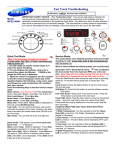
Quick Test Mode
Note: This test erases all faults and memory:
To enter press Soil, Signal, & Power simultaneously
with the power off.
1. All LED’s light up and the washer beeps as it enters the Quick Test Mode.
2. The unit displays the software version for a
second then clears the EEprom. If EEEE is displayed the PCB ass’y is defective.
3. When the version is displayed, turn the Jog-Dial
CCW so that the version disappears. Each step of
the Jog-Dial displays the following; cycle count, water level frequency, water temperature, EP condition,
test, spin, version.
Press the following keys to test the various components.
Water valves: (lock the door first) Press Temp Key to
cycle in this order: Pre-Wash, Cold, Bleach, Cold &
Bleach, Hot & then off.
Door Lock/Unlock: Press Spin Key.
Circulation/Drain Pump: Press Signal Key.
Water heater: Press Soil Level Key.
Motor test: When either Test or Spin is displayed on
the LCD, press Start/Pause key.
Test mode: You can test the clockwise and counterclockwise movement of the motor. However, the water
level must satisfy the heater water level (24300) to enter
Test mode.
Spin mode: You can test the motor at a high rpm.
EEPROM Clear Check
Power on. Press Delay Start, Signal and Power Key at
the same time. Good = Good Fail = FAiL
All memory will be cleared, including Fault Codes.
This should be done when the Main PCB is replaced.
WF511
This mode allows more detailed operation tests and troubleshooting, to enter press Signal & Extra Rinse
simultaneously with the power on.
While in Service Mode the following tests can be performed:
Quick Spin Test = Delay Start & Extra Rinse: This accelerates the drum motor from 0 to maximum RPM over a
few minutes. Note: Stay with the washer during this test,
out of balance detection is bypassed and the door may
not lock. Press the Start/Pause button during the test to hold
its spinning speed for 10 minutes before going back to Quick
Spin Test Mode.
Cycle Count = Press the Signal button to see how many
times the unit was used.
Soft Ware # = Press the Soil button to see the software version information.
Fast Time Down = Start cycle then enter service mode.
Press the Temp button to advance to the next cycle.
Fault Code Test = Press the Spin button to view the stored
fault codes – then turn Jog Dial to view error codes (Push
Start/Pause while the code is displayed to view the cycle number when the error occurred).
Peripheral (Main PCB) input Tests; Select Extra Rinse
(display shows ln).
1. Water Temperature; Turn the Jog-Dial so that the Heavy
Duty LED is turned on. The Water Temperature will be displayed in Fahrenheit.
2. Door status; Turn the Jog-Dial so that the Permanent
Press LED is turned on. The door status will be displayed
(OP if open, CL if closed).
3. Door lock; Turn the Jog-Dial so that the Sanitize LED is
turned on. The door lock Switch status will be displayed (UL if
unlocked, Lo if locked).
4. Water Frequency; Turn the Jog-Dial so that the Bedding
LED is turned on. The Water Frequency will be displayed.
12/21/2011
1
WF511
12/21/2011
2
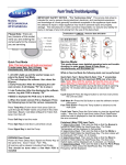
Washer Connector Checks WF520
CN11 Mems Boards
1 3.3vdc (Red)
2 Chip Select 1 (Yel)
3 Chip Select 2 (Vio)
4 Output Signal (Blu)
5 Input Signal (Wht)
6 Clock Signal (Pnk)
7 DC Common (Org)
CN10
1 Tx Disp pcb(Vio)CN7
2 Rx Disp pcb(S/Blu)CN7
3 Reset Signal Disp(Pnk)CN7 4 5vdc (Brn) CN7
5 DC Common (Org) CN7
6 15vdc (Blk)
7 Main Reset (Yel)
8 Water Level (Blu)
9 Watchdog Signal (Wht)
CN6
1 AC Pwr (L1) (Blk)
2 Door Lock Detection (Gry)
CN8
1 Motor Pwr U Phase (Red)
2 Motor Pwr V Phase (Wht)
3 Motor Pwr W Phase (Blu)
CN3 (Hall Sensor)
1 +5 vdc (Pnk)
2 Sensor Signal (Red)
3 Sensor Signal (Blu)
4 Ground (Org)
CN1
1 Door Lock Close (Blk)
2 Door Lock Open (Wht)
3 Drain Pump (Vio)
4 NC
5 Bleach Valve (Pnk)
6 Bubble Pump (Gry)
7 Pre Valve (Yel)
8 Main Valve (Blu)
9 Hot Valve (Red)
RY1 Power Relay
1 (Blu)
2 (Wht)
RY13 Washer Htr Relay
1 L1 (Blk)
2 Heater (Red)
Heater Relay Check
CN7
1 Reactor Connector Port (Red)
2 Reactor Connector Port (Red)
Test 1
Test 2
Connector CN6 Pin 2 (Gray) and RY13 (heater relay) Pin 2 (Red)
Hall Sensor Check
120VAC with the Heater On and 0VAC
with the Heater off
Test 1
Power Off, heater resistance is
16.6 Ω
Test 2
Connector CN3 Pin 4 (Orange) and Pin 2 (Red) additionally Pin 4 (Orange) and Pin 3 (blue)
N/A
Motor Check
Manually spin the drum to see the voltage change, Power On
0Vdc or 3.75Vdc
Test 1
Connector CN8 Pin 1 (Red), Pin 2 (White) and Pin 3
(Blue)
A/C Power Check
Power Off 11.5Ω across Pins 1-2, Pins 1
-3, & Pins 2-3
Test 1
300 TO 400 VAC when running
Connector CN 6 Pin 1 (Black) and RY1 Pin 1 (Blu)
Power On 120VAC
N/A
WF511
12/21/2011
Test 2
Test 2
3
Door Unlock Check
Test 1
Connector CN6 Pin 2 (Gray) and RY1 Pin 1 (Blu)
When Door is Unlocked there is a
pulse of 120VAC for a few milliseconds.
Test 1
Door Lock Check
Connector CN6 Pin 1(Black) and RY1 Pin 1 (Blu)
When Door is Locked there is a pulse
of 120VAC for a few milliseconds.
Test 1
Drain Motor Check
Connector CN1 Pin 3 (Vio) and RY1 Pin 1 (Blu)
120VAC with the pump On and 0VAC
with the pump off
With Power Off, the resistance
between CN1 Pin 1 (Blk) and Power
Relay pin 2 (Blu) will be between
47 - 57Ω
Test 2
With Power Off, the resistance
between CN1 Pin 2 (Wht) and
Power Relay pin 2 (Blu) will be between 47 - 57Ω
Test 2
With Power Off, the resistance
between CN1 Pin 3 (Vio) and
Power Relay pin 2 (Blu) should be
13.9Ω
Test 1
Water Valve Check
Connector CN6 Pin 2 (Gray) to CN1 Pin 5 (Pink),
Pin 4 (Brown) , Pin 7 (Yellow), Pin 8 (Blue), Pin 9
(Red)
Error Type
Test 2
Error Mode
LED
Water Level Sensor
LE
8
Motor Drive Error or
Hall Sensor error
3E
E3
120VAC with the Valve On and 0VAC
with the Valve off
Test 2
Power Off, valve resistance is from
1202Ω - 1245Ω
Details
LCD
Check the Hose where the sensor is connected, may be loose,
pinched, damaged or clogged. Also check the sensor it may be
disconnected or defective. The Main PCB may also be defective
Check the motor drive connector, it may be loose. The hall sensor
may be disconnected, loose or damaged . Check for a foreign object inside the motor or motor damage. The stator might be loose
or damaged. The drum might be overloaded from too many clothes
or the relay or PCB might be defective.
bE
25
Check the water valve wiring harness.
Water Supply
Error
nF
3
Check whether the water supply valve is clogged with foreign material and whether water is supplied properly.
Check for reversed fill hoses
Check water temperature, if sensed as higher than 50 ˚C in the
Wool or Lingerie cycle it will create error.
Check the relays, if they operate correctly replace the Main PCB.
Fill Hoses Reversed
nF1
Correct Hot/Cold hose connections
System Error
SF1
SF2
SF3
Replace PCB
WF511
12/21/2011
4
Error Type
Error Mode
LED
Details
LCD
Check for Foreign material entering the pump or hoses.
Drain Error
nD
1
Check to make sure the wiring harness is connected properly.
Check the water pump terminal .
Check for freezing
Power Error
2E
91
92
Make sure to check the operating voltage. (An error occurs when
under or over voltage is supplied.) Check whether a plug receptacle is used. When the connecting wires are too small (extension
cord use), a momentary low voltage may drop up to 10 V
Main PBA fault (sometimes)
PF
Momentary Power Failure
AE
Check the wire connections and terminal contacts between the sub
and main PBAs.
Communication Error
Check for disconnected wires.
Check whether the sub PCB is short circuited because of moisture.
If the main PCB’s communication circuit is faulty, replace it.
EEPROM
Fault.
11
Switch Error
E2
15
(Main Relay
Error)
Go to “EEPROM Clear Mode” If display shows “FAiL”, Replace Machine Control Board
Check whether either the Power switch or a tact switch (any button)
is stuck down.
Check whether the service PBA holding screws are fastened too
tight pinching the contacts
If the main PBA switching IC on/off error has occurred, replace the
main PBA.
SR
The “E2” error occurs if the main relay connections are incorrect.
Check the connections. If there is no error in the connections, replace the main PBA
dS
22
(Before
operation)
Door Error
dL
18
(During
operation)
LO
2
Check the door switch and latch alignment .
Check the latch for damage
Check the wiring harness to the latch.
Check the door switch. Replace if faulty.
Check the main PBA door sensing circuit. Replace if faulty.
Finally verify he operation of the Main PCB
(Unlock
Fail)
FL
4
(Lock Fail)
WF511
12/21/2011
5
Error Type
Error Mode
LED
Heater Error
Details
LCD
This can be a short or a wire disconnected to the heater circuit. This
can also be problem with the tub contacting the heater or if the water in the tub is frozen or there is no water. The error is triggered by
temperatures above 145C. If the heater has no error, this occurs
because of a PBA relay malfunction. Check the wiring harness to
the heater.
Hr
36
(Heater
Relay)
An Hr error occurs if the steam heater, is faulty, replace it.
Overflow error
9E1
EMC Filter issue or a noise spike from an external device
OE
1E
Water is supplied continually because the water level detection
does not work. - Verify the drain is working properly, the water level
detection does not work and water is supplied continually. Verify the
water valves shut off fully. Finally check the water level sensor.
29
The washing heater temperature sensor in the tub has an error.
Check the connections for the washing heater temperature sensor
connector.
Temperature
Sensor Error
Unbalance
Error
Mems or Harness Failure
Foaming
Detected
Check the type of laundry. Check whether it may cause an unbalanced situation.- Educate the consumer in this case, to press
pause, reposition the load or remove a few items. Press start to
continue and complete the wash cycle.
dC
10
8E
Check MEMS PCB ,Main PCB & Wire-harness
This occurs when too much foaming is detected. It is also displayed
while foaming is removed. When the removal is finished, the normal
cycle proceeds. (This is one of the normal operations. It is an error
for preventing non-sensing faults.)
SUdS
Sd
8E1
Front MEMS Sensor problem: Restart the cycle
If the error continues,
Replace Mems sensor
8E2
Rear MEMS Sensor problem: Restart the cycle
If the error continues,
Replace Mems sensor
Check whether the washing machine is level to the floor with respect to the original position of the washing machine prior
to service. Doing this now will reduce the need for a redo call and customer dissatisfaction.
✔ Vibrations can shorten the lifetime of the product.
Laundry Touch Up Paints
TOUCH UP PAINT, BLUE ONYX
TOUCH UP PAINT, IMPERIAL SILVER
TOUCH UP PAINT, NEAT WHITE
TOUCH UP PAINT, STRATUS GRAY
TOUCH UP PAINT, TANGO RED
WF511
12/21/2011
DH81-11980A
DH81-11981A
DH81-11982A
DH81-11983A
DH81-11984A
6
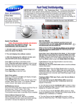
Water valve connections for the Detergent Drawer
Items Packed With Washer
BOLT-SPANER (10-13mm Wrench) DC60-40146A
ASSY HOSE WATER HOT DC97-15648B
ASSY HOSE WATER COLD DC97-15648A
MANUAL-BOOK DC68-02838A
CAP-FIXER DC67-00307A
HOSE-HANGER DC62-10278A
Stacking Kit :
(Model No : SK-5A/XAA)
Samsung washers and dryers can be stacked to maximize usable space.
An optional stacking kit is available for purchase from your Samsung retailer
When using non-HE
detergents, or using
too much detergent
for the water hardness and soil level of
the clothing, over
sudsing will occur.
When this happens
there will be leaks out
of the detergent
drawer and door.
Please advise consumer of proper detergent usage.
Location considerations
Do not install your washer
in areas where water
may freeze, since your
washer will always maintain some water in its water valve, pump, and hose
areas. This can cause
damage the belts, the
pump, hoses and other
components. Operating
temperature should be
above 60°F/16°C.
It is normal for a small amount of water
remaining in Detergent Drawer after it
completes washing. Bleach is usually
flushed out into the tub at the beginning
of the washing. Also, its compartment is
washed again during the following rinse
cycle, removing any remnants.
SUPPORT INFORMATION
Training — Plus One http://my.plus1solutions.net/clientPortals/samsung/
Help — GSPN http://service.samsungportal.com/
When installing a washer and dryer on
the first, or second floor, do not exceed
this leg adjustment height for stability.
WF511
12/21/2011
7